EP2075166A2 - Pedestrian protection system in automobiles - Google Patents
Pedestrian protection system in automobiles Download PDFInfo
- Publication number
- EP2075166A2 EP2075166A2 EP08380336A EP08380336A EP2075166A2 EP 2075166 A2 EP2075166 A2 EP 2075166A2 EP 08380336 A EP08380336 A EP 08380336A EP 08380336 A EP08380336 A EP 08380336A EP 2075166 A2 EP2075166 A2 EP 2075166A2
- Authority
- EP
- European Patent Office
- Prior art keywords
- hood
- protection system
- bumper
- pedestrian protection
- vehicle
- Prior art date
- Legal status (The legal status is an assumption and is not a legal conclusion. Google has not performed a legal analysis and makes no representation as to the accuracy of the status listed.)
- Granted
Links
- 238000000926 separation method Methods 0.000 claims abstract 8
- 230000007246 mechanism Effects 0.000 claims description 23
- 230000005540 biological transmission Effects 0.000 claims description 4
- 230000003213 activating effect Effects 0.000 claims 1
- 230000006872 improvement Effects 0.000 description 6
- 210000003141 lower extremity Anatomy 0.000 description 5
- 230000006378 damage Effects 0.000 description 4
- 230000008901 benefit Effects 0.000 description 3
- 230000004913 activation Effects 0.000 description 1
- 230000008859 change Effects 0.000 description 1
- 230000000694 effects Effects 0.000 description 1
- 239000003344 environmental pollutant Substances 0.000 description 1
- 210000003414 extremity Anatomy 0.000 description 1
- 239000007789 gas Substances 0.000 description 1
- 238000005457 optimization Methods 0.000 description 1
- 231100000719 pollutant Toxicity 0.000 description 1
- 230000009467 reduction Effects 0.000 description 1
- 230000008439 repair process Effects 0.000 description 1
- 230000000284 resting effect Effects 0.000 description 1
Images


Classifications
-
- B—PERFORMING OPERATIONS; TRANSPORTING
- B60—VEHICLES IN GENERAL
- B60R—VEHICLES, VEHICLE FITTINGS, OR VEHICLE PARTS, NOT OTHERWISE PROVIDED FOR
- B60R21/00—Arrangements or fittings on vehicles for protecting or preventing injuries to occupants or pedestrians in case of accidents or other traffic risks
- B60R21/34—Protecting non-occupants of a vehicle, e.g. pedestrians
- B60R21/38—Protecting non-occupants of a vehicle, e.g. pedestrians using means for lifting bonnets
-
- B—PERFORMING OPERATIONS; TRANSPORTING
- B60—VEHICLES IN GENERAL
- B60R—VEHICLES, VEHICLE FITTINGS, OR VEHICLE PARTS, NOT OTHERWISE PROVIDED FOR
- B60R21/00—Arrangements or fittings on vehicles for protecting or preventing injuries to occupants or pedestrians in case of accidents or other traffic risks
- B60R21/34—Protecting non-occupants of a vehicle, e.g. pedestrians
-
- E—FIXED CONSTRUCTIONS
- E05—LOCKS; KEYS; WINDOW OR DOOR FITTINGS; SAFES
- E05B—LOCKS; ACCESSORIES THEREFOR; HANDCUFFS
- E05B77/00—Vehicle locks characterised by special functions or purposes
- E05B77/02—Vehicle locks characterised by special functions or purposes for accident situations
- E05B77/08—Arrangements for protection of pedestrians
-
- B—PERFORMING OPERATIONS; TRANSPORTING
- B60—VEHICLES IN GENERAL
- B60R—VEHICLES, VEHICLE FITTINGS, OR VEHICLE PARTS, NOT OTHERWISE PROVIDED FOR
- B60R19/00—Wheel guards; Radiator guards, e.g. grilles; Obstruction removers; Fittings damping bouncing force in collisions
- B60R19/02—Bumpers, i.e. impact receiving or absorbing members for protecting vehicles or fending off blows from other vehicles or objects
- B60R19/24—Arrangements for mounting bumpers on vehicles
- B60R19/38—Arrangements for mounting bumpers on vehicles adjustably or movably mounted, e.g. horizontally displaceable for securing a space between parked vehicles
- B60R19/40—Arrangements for mounting bumpers on vehicles adjustably or movably mounted, e.g. horizontally displaceable for securing a space between parked vehicles in the direction of an obstacle before a collision, or extending during driving of the vehicle, i.e. to increase the energy absorption capacity of the bumper
Definitions
- the present invention refers to a pedestrian protection system in automobiles, and specifically to a pedestrian protection system applied to the front part of the vehicle, which is the area where the pedestrian impacts in case of collision.
- the system of the invention is intended to reduce the effects on the pedestrian, in case of collision, produced by the impact against the front bumper and/or hood of the engine compartment.
- the present invention refers to a pedestrian protection system in automobiles which eliminates the aforementioned problems by offering a wider protection, covering possible impacts against the hood and the front bumper.
- the front bumper of the vehicle can be the first element against which the pedestrian impacts, at leg level, in case of collision. Behind the front bumper there are rigid components, such as the different radiators of the vehicle, chassis cross bars, etc., which produce serious injuries on the pedestrian's extremities at the moment of the impact.
- the system of the invention is based on producing a volume increase both between the hood and the rigid elements of the engine, as well as between the front bumper and the rigid elements behind it.
- the aforementioned volume increase is variable, and inversely proportional to the vehicle speed, that is to say, the higher the speed, the less volume increase, which enables to improve the aerodynamic conditions of the vehicle, while the lower the speed while circulating in urban areas where a collision with a pedestrian is more likely to happen, the higher the volume increase is, to offer more protection.
- the volume variation indicated is achieved by the movement of the hood and bumper of the vehicle along the X and Z shafts, through simple constitution mechanism and performance.
- the system being claimed consists of a mechanism installed in the anchorage area of the engine hood and a mobile hinge.
- the mechanism comprises a mobile lock of the engine hood which can rotate on a shaft, thanks to an electric engine.
- the hinges of the engine hood have to be modified if the device is to be installed, since the engine hood will move both in the X shaft and in the Z shaft.
- the drive mechanism comprises modified hinges which enable the movement of the entire engine hood thanks to a track which enables the hinge to move along it, while keeping a correct opening at all times. Thanks to the aforementioned system two movements of the hood are achieved, namely rotation and translation, which have to be transmitted to the bumper. This transmission between the engine hood and the bumper is carried out through a mechanical joint between these two elements, through a joint or any other fixing system known. This joint enables all engine hood movements to be transmitted to the bumper, moving the two elements as if they were one.
- the system governed by the control unit corresponding to the security systems, can have three basic performance positions, according, in all cases, to the speed parameter register by the control unit, which will adapt the system to the security or aerodynamic conditions and which will be named as position 0, position 1 and position 2.
- Position 0 is the maximum security position. This position can be activated for speeds under 25 km/hour, which are typically used in urban areas, where top pedestrian protection is needed. In this position the assembly of the engine hood and bumper is in its most forward position, offering a considerable extra volume.
- Position 1 offers medium security. This position can be activated for speeds between 25 km/hour and 100 km/hour, allowing for good pedestrian protection in urban areas, without penalizing the driver's vision or the aerodynamic efficiency of the vehicle on fast lanes.
- the extra space between the mobile elements and the rigid elements is lightly inferior to position 0, but preserves the desired effectiveness of the system.
- the system of the invention enables to attain an important improvement with regard to pedestrian security, considerably reducing lower extremities injuries and keeping the correct protection in other areas, such as the head or torso.
- the main advantage of the proposed system with respect to the other existing systems is the simplicity of its use, eliminating expensive complex pyrotechnic systems, which are difficult to install.
- Figures 1 to 3 show a longitudinal section of the hood 1, which shows the front compartment of the vehicle where the engine 15 is located.
- the hood 1 is mechanically connected to the front bumper 2 by any mechanical system generally indicated using the reference 3.
- the hood 1 is mounted using a modified hinge 4, to which a track 5 has been incorporated, along which said hinge can move in the X direction.
- the hood 1 is also related to a rotation mechanism 6, which is connected to the anchorage or lock 7 of said hood and which can be activated through an electric engine 8.
- the assembly of the hood 1 and the bumper 2 can move along the shafts X and Z, since the bumper 2 and the hood 1 being mechanically joined, both components move as if they were one.
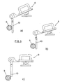
- the rotation mechanism 6 can be directly connected to the electric engine 8 or, as it can be seen in figure 4 , it can be engaged with a rack 10 which is connected to the mechanism 6 through an intermediate arm 11 which is articulated according to the shaft 12 with the rack 10 and according to the shaft 13 with said mechanism 6.
- the intermediate transmission mechanism described with reference to figure 4 can be dispensed with, directly connecting the drive mechanism 6 to the electric engine 8 or using a simple gear assembly.
- a transmission mechanism like the one shown in figure 4 , which enables to place the electric engine 8 away from the drive mechanism 6.
- the assembly shown in figure 4 can have, for example, any of the three positions shown in figure 5 and indicated as a), b) and c), in which the hood 1 and front bumper 2 will be placed in the positions shown in figures 1, 2 and 3 , which are indicated as "position 0", "position 1" and "position 2".
- the electric engine 8 controlled by the control unit, positions the assembly of the hood 1 and bumper 2 in its highest position, starting at the resting position.
- the hinge 4 is in the highest position of the rack 5, thus allowing a slight elevation of the part of the hood 1 that is closest to the car windshield, preventing the head of a pedestrian who has been in a collision from hitting it.
- Position 1 shown in figure 2 , with the rotation mechanism 6 in position b) of figure 5 , will be a position of medium security. This position is activated, for example, for speeds ranging from 25 km/hour to 100 km/hour.
- the extra space between the mobile elements and the rigid elements is slightly smaller than in the case of "position 0", previously described with reference to figure 1 , but it maintains the desired effectiveness of the system.
- the assembly formed by the hood 1 and the bumper 2 is slightly retracted with respect to position 0, thus reducing part of the free space between the elements of engine 15 of the vehicle and the hood 1, but maintaining a good degree of protection, both for the pedestrian's head and his/her lower extremities and offering a good vision and a small aerodynamic improvement to the user of the vehicle.
- Figure 3 shows the hood 1 and bumper 2 in "position 2", which is the most aerodynamic one, with the rotation mechanism 6, in position c) of figure 5 .
- This position can be activated for speeds starting at 100 km/hour and it prioritizes the aerodynamic efficiency of the vehicle, at the expense of pedestrian security.
- the assembly of the hood 1 and the bumper 2 is entirely retracted in this position, favoring the aerodynamic profile of the vehicle and improving its features.
- hinge 4 is in the most retracted position of rack 5, considerably limiting the effectiveness of the system for pedestrian protection but slightly increasing the aerodynamic characteristics of the vehicle, which translates into an improved consumption and a reduction of pollutant emissions.
- Figures 2 and 3 show through a discontinuous line and with reference to numbers 1 and 2, the hood and front bumper condition in position 0 of figure 1 , where it is possible to see the movement of these components to "positions 2 and 3" and the variation in volume between them and the rigid elements of the engine 15 of the vehicle.
Landscapes
- Engineering & Computer Science (AREA)
- Mechanical Engineering (AREA)
- Superstructure Of Vehicle (AREA)
- Body Structure For Vehicles (AREA)
Abstract
Description
- The present invention refers to a pedestrian protection system in automobiles, and specifically to a pedestrian protection system applied to the front part of the vehicle, which is the area where the pedestrian impacts in case of collision.
- The system of the invention is intended to reduce the effects on the pedestrian, in case of collision, produced by the impact against the front bumper and/or hood of the engine compartment.
- There are already well-known protection systems for pedestrians, intended to reduce the damages the pedestrian could suffer in case of collision, as a result of the impact against the hood of the vehicle. These systems are based on a volume increase between the hood and the rigid elements of the engine.
- Nowadays there exist different solutions intended to increase the volume between the hood and the rigid elements of the engine, mainly based on complex elevation or pyrotechnic systems which move the entire or part of the hood of the engine following a Z direction, thus attaining the desired volume increase or a change of direction of the pedestrian's head after the impact.
- The main problem of these current solutions is the lack of an efficient system which compiles with the requirements related to pedestrian protection. Most existing solutions on the market are intended to produce an extra volume increase between the hood of the engine and the rigid elements, neglecting the protection of the lower extremities, which are the first to receive the impact.
- An additional problem is the complexity of the protection systems for pedestrians available nowadays, which are based on complex mechanisms for increasing the entire or part of the hood of the engine, which increase the final cost of the system as well as their repair or replacement, limiting its use to medium-top range vehicles. Another notable problem is that the majority of the systems presented cannot be used more than once without replacement and, additionally, they do not have any aerodynamic improvement to the vehicle as a whole.
- The present invention refers to a pedestrian protection system in automobiles which eliminates the aforementioned problems by offering a wider protection, covering possible impacts against the hood and the front bumper.
- It is important to take into account that the front bumper of the vehicle can be the first element against which the pedestrian impacts, at leg level, in case of collision. Behind the front bumper there are rigid components, such as the different radiators of the vehicle, chassis cross bars, etc., which produce serious injuries on the pedestrian's extremities at the moment of the impact.
- The system of the invention is based on producing a volume increase both between the hood and the rigid elements of the engine, as well as between the front bumper and the rigid elements behind it.
- According to another characteristic of the invention, the aforementioned volume increase is variable, and inversely proportional to the vehicle speed, that is to say, the higher the speed, the less volume increase, which enables to improve the aerodynamic conditions of the vehicle, while the lower the speed while circulating in urban areas where a collision with a pedestrian is more likely to happen, the higher the volume increase is, to offer more protection.
- The volume variation indicated is achieved by the movement of the hood and bumper of the vehicle along the X and Z shafts, through simple constitution mechanism and performance.
- Thanks to the new protection system for pedestrians, there is an improvement in reducing damages produced during impacts, especially in the lower extremities. This improvement in the protection of the pedestrian's lower extremities is achieved by the extra volume increase between the rigid elements protected by the bumper, especially winches and chassis cross bars, and the body of the bumper itself. The system being claimed consists of a mechanism installed in the anchorage area of the engine hood and a mobile hinge. The mechanism comprises a mobile lock of the engine hood which can rotate on a shaft, thanks to an electric engine. The hinges of the engine hood have to be modified if the device is to be installed, since the engine hood will move both in the X shaft and in the Z shaft. For this reason, the drive mechanism comprises modified hinges which enable the movement of the entire engine hood thanks to a track which enables the hinge to move along it, while keeping a correct opening at all times. Thanks to the aforementioned system two movements of the hood are achieved, namely rotation and translation, which have to be transmitted to the bumper. This transmission between the engine hood and the bumper is carried out through a mechanical joint between these two elements, through a joint or any other fixing system known. This joint enables all engine hood movements to be transmitted to the bumper, moving the two elements as if they were one. The system, governed by the control unit corresponding to the security systems, can have three basic performance positions, according, in all cases, to the speed parameter register by the control unit, which will adapt the system to the security or aerodynamic conditions and which will be named as position 0,
position 1 andposition 2. - Position 0 is the maximum security position. This position can be activated for speeds under 25 km/hour, which are typically used in urban areas, where top pedestrian protection is needed. In this position the assembly of the engine hood and bumper is in its most forward position, offering a considerable extra volume.
-
Position 1 offers medium security. This position can be activated for speeds between 25 km/hour and 100 km/hour, allowing for good pedestrian protection in urban areas, without penalizing the driver's vision or the aerodynamic efficiency of the vehicle on fast lanes. The extra space between the mobile elements and the rigid elements is lightly inferior to position 0, but preserves the desired effectiveness of the system. - In
position 2 maximum aerodynamics is attained. This position will be activated for speeds starting at 100 km/hour and prioritizes the aeoridamic effectiveness of the vehicle, penalizing pedestrian security. The assembly of the engine hood and the bumper are completely retracted in this position, favoring the aeorodinamic profile of the vehicle and improving its features. - The system of the invention enables to attain an important improvement with regard to pedestrian security, considerably reducing lower extremities injuries and keeping the correct protection in other areas, such as the head or torso. The main advantage of the proposed system with respect to the other existing systems is the simplicity of its use, eliminating expensive complex pyrotechnic systems, which are difficult to install.
- Additionally, it offers the advantage of having a system for aerodynamic improvement, which enables the optimization of the aerodynamic coefficient of the vehicle, thus slightly reducing consumption and, therefore, reducing medium emissions of gases which are harmful for the atmosphere.
- The attached drawings show a non-limiting example of an embodiment, which will enable to understand better the characteristics and advantages of the invention.
- In the drawings:
-
Figure 1 shows, in a schematic longitudinal section, a front bumper and the hood of the engine compartment, mounted using the system of the invention with position 0 for maximum protection. -
Figure 2 shows a similar view tofigure 1 , with the bumper and hood inposition 1. -
Figure 3 shows a similar view tofigure 1 , with the bumper and hood inposition 2. -
Figure 4 shows a perspective view of the drive mechanism for moving the bumper and the hood, between the different positions. -
Figure 5 shows a lateral view of the drive mechanism positions corresponding to the situations of the bumper and hood offigures 1 to 3 . -
Figures 1 to 3 show a longitudinal section of thehood 1, which shows the front compartment of the vehicle where theengine 15 is located. Thehood 1 is mechanically connected to thefront bumper 2 by any mechanical system generally indicated using thereference 3. - The
hood 1 is mounted using a modifiedhinge 4, to which atrack 5 has been incorporated, along which said hinge can move in the X direction. Thehood 1 is also related to arotation mechanism 6, which is connected to the anchorage orlock 7 of said hood and which can be activated through anelectric engine 8. - Through the
drive mechanism 6 and thanks to the possibility of moving thehinge 4 along thetrack 5, the assembly of thehood 1 and thebumper 2 can move along the shafts X and Z, since thebumper 2 and thehood 1 being mechanically joined, both components move as if they were one. - The
rotation mechanism 6 can be directly connected to theelectric engine 8 or, as it can be seen infigure 4 , it can be engaged with arack 10 which is connected to themechanism 6 through anintermediate arm 11 which is articulated according to theshaft 12 with therack 10 and according to theshaft 13 with saidmechanism 6. - If there is enough space in the engine hole, the intermediate transmission mechanism described with reference to
figure 4 can be dispensed with, directly connecting thedrive mechanism 6 to theelectric engine 8 or using a simple gear assembly. By contrast, if there is no space, it will be necessary to use a transmission mechanism, like the one shown infigure 4 , which enables to place theelectric engine 8 away from thedrive mechanism 6. - The activation of the
electric engine 8 will be governed by the control unit corresponding to the security systems of the vehicle and, according to its speed, the assembly shown infigure 4 can have, for example, any of the three positions shown infigure 5 and indicated as a), b) and c), in which thehood 1 andfront bumper 2 will be placed in the positions shown infigures 1, 2 and3 , which are indicated as "position 0", "position 1" and "position 2". - "Position 0", shown in
figure 1 , with therotation mechanism 6 in position a) offigure 5 , is the one of maximum security. This position is activated for speeds under 25 km/hour, for example, which is typical of urban areas, where maximum pedestrian protection is needed. In this position the assembly of thehood 1 andbumper 2 is furthest away from the rigid elements of theengine 15 of the vehicle, offering a considerable extra volume. - The
electric engine 8, controlled by the control unit, positions the assembly of thehood 1 andbumper 2 in its highest position, starting at the resting position. In this situation, thehinge 4 is in the highest position of therack 5, thus allowing a slight elevation of the part of thehood 1 that is closest to the car windshield, preventing the head of a pedestrian who has been in a collision from hitting it. - "
Position 1", shown infigure 2 , with therotation mechanism 6 in position b) offigure 5 , will be a position of medium security. This position is activated, for example, for speeds ranging from 25 km/hour to 100 km/hour. The extra space between the mobile elements and the rigid elements is slightly smaller than in the case of "position 0", previously described with reference tofigure 1 , but it maintains the desired effectiveness of the system. The assembly formed by thehood 1 and thebumper 2 is slightly retracted with respect to position 0, thus reducing part of the free space between the elements ofengine 15 of the vehicle and thehood 1, but maintaining a good degree of protection, both for the pedestrian's head and his/her lower extremities and offering a good vision and a small aerodynamic improvement to the user of the vehicle. -
Figure 3 shows thehood 1 andbumper 2 in "position 2", which is the most aerodynamic one, with therotation mechanism 6, in position c) offigure 5 . This position can be activated for speeds starting at 100 km/hour and it prioritizes the aerodynamic efficiency of the vehicle, at the expense of pedestrian security. The assembly of thehood 1 and thebumper 2 is entirely retracted in this position, favoring the aerodynamic profile of the vehicle and improving its features. In thisposition hinge 4 is in the most retracted position ofrack 5, considerably limiting the effectiveness of the system for pedestrian protection but slightly increasing the aerodynamic characteristics of the vehicle, which translates into an improved consumption and a reduction of pollutant emissions. -
Figures 2 and3 show through a discontinuous line and with reference tonumbers figure 1 , where it is possible to see the movement of these components to "positions engine 15 of the vehicle.
Claims (6)
- Pedestrian protection system in automobiles, wherein the vehicles have a front bumper and a hood which covers the engine compartment, characterized in that the front bumper and hood mounted can move along the shafts X and Z, between positions of maximum and minimum separation with respect to the rigid elements covered by said bumper and hood, being this separation inversely proportional to the speed of the vehicle.
- Pedestrian protection system in automobiles according to claim 1, characterized in that the movement of the hood and front bumper is produced by a drive mechanism connected to the anchorage of the hood and by an mobile articulation for said hood, being the front bumper connected to said hood, for it to be dragged by it when it moves.
- Pedestrian protection system in automobiles according to claim 2, characterized in that the aforementioned drive mechanism is governed by a central unit corresponding to the security means of the vehicle, according to the speed of said vehicle, being the separation of the hood and bumper in inverse relation to the speed of the vehicle.
- Pedestrian protection system in automobiles according to claims 2 and 3, characterized in that front bumper and hood can be moved by activating the drive mechanism, between an extreme position of maximum separation and safety, for speeds in urban areas; a position of minimum separation and safety, for speeds in highways and fast lanes; and an intermediate position of separation and safety, for speeds between driving speeds in urban areas and driving speeds in fast lanes.
- Pedestrian protection system in automobiles according to claim 2, characterized in that the drive mechanism comprises an electric engine related to the anchorage elements of the hood by a transmission device which produces the lineal movement of said elements, following the direction of the Z shaft.
- Pedestrian protection system in automobiles according to claim 2, characterized in that the mobile articulation of the hood comprises a hinge mounted on a rack, along which it can move in the direction of shafts X and Z.
Applications Claiming Priority (1)
| Application Number | Priority Date | Filing Date | Title |
|---|---|---|---|
| ES200703469A ES2335460B1 (en) | 2007-12-28 | 2007-12-28 | PROTECTION SYSTEM FOR PEDESTRIES IN AUTOMOBILE VEHICLES. |
Publications (3)
| Publication Number | Publication Date |
|---|---|
| EP2075166A2 true EP2075166A2 (en) | 2009-07-01 |
| EP2075166A3 EP2075166A3 (en) | 2009-09-16 |
| EP2075166B1 EP2075166B1 (en) | 2011-08-17 |
Family
ID=40379019
Family Applications (1)
| Application Number | Title | Priority Date | Filing Date |
|---|---|---|---|
| EP08380336A Not-in-force EP2075166B1 (en) | 2007-12-28 | 2008-12-12 | Pedestrian protection system in automobiles |
Country Status (2)
| Country | Link |
|---|---|
| EP (1) | EP2075166B1 (en) |
| ES (2) | ES2335460B1 (en) |
Family Cites Families (6)
| Publication number | Priority date | Publication date | Assignee | Title |
|---|---|---|---|---|
| DE3003568A1 (en) * | 1980-02-01 | 1981-08-06 | Daimler-Benz Ag, 7000 Stuttgart | SHOCK PROTECTION DEVICE FOR VEHICLES, IN PARTICULAR MOTOR VEHICLES |
| US6089628A (en) * | 1998-09-02 | 2000-07-18 | Ford Global Technologies, Inc. | Stiffener assembly for bumper system of motor vehicles |
| DE19922459C1 (en) * | 1999-05-17 | 2001-02-01 | Edscha Ag | Front hood arrangement |
| DE10037051A1 (en) * | 2000-07-29 | 2002-02-28 | Acts Gmbh & Co Kg | Car with bonnet (hood) acting as safety device has bonnet pivoted at bumper height and closing mechanism in rear region of bumper |
| US7192079B2 (en) * | 2004-03-26 | 2007-03-20 | Autoliv Asp, Inc. | Pedestrian protection apparatus for motor vehicles |
| US20070125589A1 (en) * | 2005-12-06 | 2007-06-07 | Murphy Morgan D | Situationally dependent vehicle structure for pedestrian protection |
-
2007
- 2007-12-28 ES ES200703469A patent/ES2335460B1/en not_active Expired - Fee Related
-
2008
- 2008-12-12 ES ES08380336T patent/ES2371585T3/en active Active
- 2008-12-12 EP EP08380336A patent/EP2075166B1/en not_active Not-in-force
Non-Patent Citations (1)
| Title |
|---|
| None |
Also Published As
| Publication number | Publication date |
|---|---|
| EP2075166B1 (en) | 2011-08-17 |
| ES2335460A1 (en) | 2010-03-26 |
| ES2371585T3 (en) | 2012-01-05 |
| ES2335460B1 (en) | 2011-02-14 |
| EP2075166A3 (en) | 2009-09-16 |
Similar Documents
| Publication | Publication Date | Title |
|---|---|---|
| US5785368A (en) | Vehicle with impact protection unit | |
| ES2864626T3 (en) | Support device for a motor vehicle | |
| US4685779A (en) | Combined forward and rearward viewing mirror assembly for automotive vehicles | |
| MXPA01011776A (en) | Front hood assembly. | |
| JP4277798B2 (en) | Electric power steering device | |
| JP2000127991A (en) | Shock absorbing steering device and automobile | |
| EP2075166B1 (en) | Pedestrian protection system in automobiles | |
| CA2792196C (en) | Front arrangement for a vehicle, in particular for a rail vehicle, having a windshield washer device | |
| CN202574005U (en) | Automobile rear-view device | |
| EP1842744B1 (en) | A grille and bonnet assembly for a vehicle | |
| KR20200039036A (en) | Sensor Fitted type Active Bumper and Autonomous Vehicle thereof | |
| EP3689719B1 (en) | Aerodynamic device for a motor vehicle | |
| KR102684879B1 (en) | Automatic Electric Column with Impact Absorption Structure | |
| JP4909780B2 (en) | Front spoiler device | |
| WO2010070303A1 (en) | A safety arrangement | |
| JP3115345U (en) | Fender integrated side mirror for automobile | |
| JP5013914B2 (en) | Automobile hood shock absorption structure | |
| JP3216297U (en) | Auxiliary mirror used to assist rear vehicles | |
| KR102344508B1 (en) | Side Camera System For Vehicle | |
| US20080258489A1 (en) | Safety Device for a Motor Vehicle | |
| KR100693635B1 (en) | Steering rack stroke adjustment structure of car | |
| KR20060053612A (en) | Hood control system of car | |
| KR200439329Y1 (en) | Automotive multi-axis rearview mirror structure | |
| JP6945425B2 (en) | Work vehicle | |
| CN103359004A (en) | Automobile exterior rear-view mirror mounting structure and automobile |
Legal Events
| Date | Code | Title | Description |
|---|---|---|---|
| PUAI | Public reference made under article 153(3) epc to a published international application that has entered the european phase |
Free format text: ORIGINAL CODE: 0009012 |
|
| AK | Designated contracting states |
Kind code of ref document: A2 Designated state(s): AT BE BG CH CY CZ DE DK EE ES FI FR GB GR HR HU IE IS IT LI LT LU LV MC MT NL NO PL PT RO SE SI SK TR |
|
| AX | Request for extension of the european patent |
Extension state: AL BA MK RS |
|
| PUAL | Search report despatched |
Free format text: ORIGINAL CODE: 0009013 |
|
| AK | Designated contracting states |
Kind code of ref document: A3 Designated state(s): AT BE BG CH CY CZ DE DK EE ES FI FR GB GR HR HU IE IS IT LI LT LU LV MC MT NL NO PL PT RO SE SI SK TR |
|
| AX | Request for extension of the european patent |
Extension state: AL BA MK RS |
|
| 17P | Request for examination filed |
Effective date: 20100315 |
|
| AKX | Designation fees paid |
Designated state(s): DE ES FR GB IT |
|
| 17Q | First examination report despatched |
Effective date: 20100423 |
|
| GRAP | Despatch of communication of intention to grant a patent |
Free format text: ORIGINAL CODE: EPIDOSNIGR1 |
|
| GRAS | Grant fee paid |
Free format text: ORIGINAL CODE: EPIDOSNIGR3 |
|
| GRAA | (expected) grant |
Free format text: ORIGINAL CODE: 0009210 |
|
| AK | Designated contracting states |
Kind code of ref document: B1 Designated state(s): DE ES FR GB IT |
|
| REG | Reference to a national code |
Ref country code: GB Ref legal event code: FG4D |
|
| REG | Reference to a national code |
Ref country code: DE Ref legal event code: R096 Ref document number: 602008008926 Country of ref document: DE Effective date: 20111117 |
|
| REG | Reference to a national code |
Ref country code: ES Ref legal event code: FG2A Ref document number: 2371585 Country of ref document: ES Kind code of ref document: T3 Effective date: 20120105 |
|
| PGFP | Annual fee paid to national office [announced via postgrant information from national office to epo] |
Ref country code: ES Payment date: 20111227 Year of fee payment: 4 Ref country code: FR Payment date: 20120105 Year of fee payment: 4 |
|
| PGFP | Annual fee paid to national office [announced via postgrant information from national office to epo] |
Ref country code: DE Payment date: 20120111 Year of fee payment: 4 |
|
| PLBE | No opposition filed within time limit |
Free format text: ORIGINAL CODE: 0009261 |
|
| STAA | Information on the status of an ep patent application or granted ep patent |
Free format text: STATUS: NO OPPOSITION FILED WITHIN TIME LIMIT |
|
| 26N | No opposition filed |
Effective date: 20120521 |
|
| REG | Reference to a national code |
Ref country code: DE Ref legal event code: R097 Ref document number: 602008008926 Country of ref document: DE Effective date: 20120521 |
|
| GBPC | Gb: european patent ceased through non-payment of renewal fee |
Effective date: 20121212 |
|
| REG | Reference to a national code |
Ref country code: FR Ref legal event code: ST Effective date: 20130830 |
|
| REG | Reference to a national code |
Ref country code: DE Ref legal event code: R119 Ref document number: 602008008926 Country of ref document: DE Effective date: 20130702 |
|
| PG25 | Lapsed in a contracting state [announced via postgrant information from national office to epo] |
Ref country code: DE Free format text: LAPSE BECAUSE OF NON-PAYMENT OF DUE FEES Effective date: 20130702 |
|
| PG25 | Lapsed in a contracting state [announced via postgrant information from national office to epo] |
Ref country code: FR Free format text: LAPSE BECAUSE OF NON-PAYMENT OF DUE FEES Effective date: 20130102 Ref country code: GB Free format text: LAPSE BECAUSE OF NON-PAYMENT OF DUE FEES Effective date: 20121212 |
|
| PG25 | Lapsed in a contracting state [announced via postgrant information from national office to epo] |
Ref country code: IT Free format text: LAPSE BECAUSE OF NON-PAYMENT OF DUE FEES Effective date: 20121212 |
|
| REG | Reference to a national code |
Ref country code: ES Ref legal event code: FD2A Effective date: 20140306 |
|
| PG25 | Lapsed in a contracting state [announced via postgrant information from national office to epo] |
Ref country code: ES Free format text: LAPSE BECAUSE OF NON-PAYMENT OF DUE FEES Effective date: 20121213 |