EP2073762B1 - Dispositif de remplacement total d'un disque - Google Patents
Dispositif de remplacement total d'un disque Download PDFInfo
- Publication number
- EP2073762B1 EP2073762B1 EP06775148A EP06775148A EP2073762B1 EP 2073762 B1 EP2073762 B1 EP 2073762B1 EP 06775148 A EP06775148 A EP 06775148A EP 06775148 A EP06775148 A EP 06775148A EP 2073762 B1 EP2073762 B1 EP 2073762B1
- Authority
- EP
- European Patent Office
- Prior art keywords
- intermediate means
- apposition
- joint component
- plate
- fit
- Prior art date
- Legal status (The legal status is an assumption and is not a legal conclusion. Google has not performed a legal analysis and makes no representation as to the accuracy of the status listed.)
- Active
Links
- 239000000463 material Substances 0.000 claims description 21
- 239000000919 ceramic Substances 0.000 claims description 11
- RTAQQCXQSZGOHL-UHFFFAOYSA-N Titanium Chemical compound [Ti] RTAQQCXQSZGOHL-UHFFFAOYSA-N 0.000 claims description 8
- PNEYBMLMFCGWSK-UHFFFAOYSA-N Alumina Chemical compound [O-2].[O-2].[O-2].[Al+3].[Al+3] PNEYBMLMFCGWSK-UHFFFAOYSA-N 0.000 claims description 6
- 229910045601 alloy Inorganic materials 0.000 claims description 6
- 239000000956 alloy Substances 0.000 claims description 6
- 239000004696 Poly ether ether ketone Substances 0.000 claims description 4
- JUPQTSLXMOCDHR-UHFFFAOYSA-N benzene-1,4-diol;bis(4-fluorophenyl)methanone Chemical compound OC1=CC=C(O)C=C1.C1=CC(F)=CC=C1C(=O)C1=CC=C(F)C=C1 JUPQTSLXMOCDHR-UHFFFAOYSA-N 0.000 claims description 4
- 229920002530 polyetherether ketone Polymers 0.000 claims description 4
- 239000010936 titanium Substances 0.000 claims description 4
- 229920001652 poly(etherketoneketone) Polymers 0.000 claims description 3
- 229910052719 titanium Inorganic materials 0.000 claims description 3
- -1 CoCrMo Substances 0.000 claims description 2
- BPQQTUXANYXVAA-UHFFFAOYSA-N Orthosilicate Chemical compound [O-][Si]([O-])([O-])[O-] BPQQTUXANYXVAA-UHFFFAOYSA-N 0.000 claims description 2
- 239000004411 aluminium Substances 0.000 claims description 2
- 229910052782 aluminium Inorganic materials 0.000 claims description 2
- XAGFODPZIPBFFR-UHFFFAOYSA-N aluminium Chemical compound [Al] XAGFODPZIPBFFR-UHFFFAOYSA-N 0.000 claims description 2
- 230000005489 elastic deformation Effects 0.000 claims description 2
- RVTZCBVAJQQJTK-UHFFFAOYSA-N oxygen(2-);zirconium(4+) Chemical compound [O-2].[O-2].[Zr+4] RVTZCBVAJQQJTK-UHFFFAOYSA-N 0.000 claims description 2
- 239000004033 plastic Substances 0.000 claims description 2
- 229920003023 plastic Polymers 0.000 claims description 2
- 239000010935 stainless steel Substances 0.000 claims description 2
- 229910001220 stainless steel Inorganic materials 0.000 claims description 2
- 229910001928 zirconium oxide Inorganic materials 0.000 claims description 2
- 210000000988 bone and bone Anatomy 0.000 description 4
- 230000006835 compression Effects 0.000 description 4
- 238000007906 compression Methods 0.000 description 4
- 239000007943 implant Substances 0.000 description 4
- 238000003780 insertion Methods 0.000 description 4
- 230000037431 insertion Effects 0.000 description 4
- 229910010293 ceramic material Inorganic materials 0.000 description 3
- 229910052751 metal Inorganic materials 0.000 description 3
- 239000002184 metal Substances 0.000 description 3
- 229920001169 thermoplastic Polymers 0.000 description 3
- 229910001069 Ti alloy Inorganic materials 0.000 description 2
- 238000004519 manufacturing process Methods 0.000 description 2
- 230000000149 penetrating effect Effects 0.000 description 2
- 230000002093 peripheral effect Effects 0.000 description 2
- 229920000642 polymer Polymers 0.000 description 2
- 229910000601 superalloy Inorganic materials 0.000 description 2
- 239000004416 thermosoftening plastic Substances 0.000 description 2
- OKTJSMMVPCPJKN-UHFFFAOYSA-N Carbon Chemical compound [C] OKTJSMMVPCPJKN-UHFFFAOYSA-N 0.000 description 1
- 239000004699 Ultra-high molecular weight polyethylene Substances 0.000 description 1
- 238000005299 abrasion Methods 0.000 description 1
- 210000004204 blood vessel Anatomy 0.000 description 1
- 229910052799 carbon Inorganic materials 0.000 description 1
- 239000013013 elastic material Substances 0.000 description 1
- 239000012634 fragment Substances 0.000 description 1
- 238000011065 in-situ storage Methods 0.000 description 1
- 229920002521 macromolecule Polymers 0.000 description 1
- 229910001092 metal group alloy Inorganic materials 0.000 description 1
- 239000007769 metal material Substances 0.000 description 1
- 238000000034 method Methods 0.000 description 1
- 239000002245 particle Substances 0.000 description 1
- 229920001343 polytetrafluoroethylene Polymers 0.000 description 1
- 239000004810 polytetrafluoroethylene Substances 0.000 description 1
- 238000004321 preservation Methods 0.000 description 1
- 230000002265 prevention Effects 0.000 description 1
- 230000000246 remedial effect Effects 0.000 description 1
- 229920006126 semicrystalline polymer Polymers 0.000 description 1
- 230000002269 spontaneous effect Effects 0.000 description 1
- 229920000785 ultra high molecular weight polyethylene Polymers 0.000 description 1
Images


Classifications
-
- A—HUMAN NECESSITIES
- A61—MEDICAL OR VETERINARY SCIENCE; HYGIENE
- A61F—FILTERS IMPLANTABLE INTO BLOOD VESSELS; PROSTHESES; DEVICES PROVIDING PATENCY TO, OR PREVENTING COLLAPSING OF, TUBULAR STRUCTURES OF THE BODY, e.g. STENTS; ORTHOPAEDIC, NURSING OR CONTRACEPTIVE DEVICES; FOMENTATION; TREATMENT OR PROTECTION OF EYES OR EARS; BANDAGES, DRESSINGS OR ABSORBENT PADS; FIRST-AID KITS
- A61F2/00—Filters implantable into blood vessels; Prostheses, i.e. artificial substitutes or replacements for parts of the body; Appliances for connecting them with the body; Devices providing patency to, or preventing collapsing of, tubular structures of the body, e.g. stents
- A61F2/02—Prostheses implantable into the body
- A61F2/30—Joints
- A61F2/44—Joints for the spine, e.g. vertebrae, spinal discs
- A61F2/442—Intervertebral or spinal discs, e.g. resilient
- A61F2/4425—Intervertebral or spinal discs, e.g. resilient made of articulated components
-
- A—HUMAN NECESSITIES
- A61—MEDICAL OR VETERINARY SCIENCE; HYGIENE
- A61F—FILTERS IMPLANTABLE INTO BLOOD VESSELS; PROSTHESES; DEVICES PROVIDING PATENCY TO, OR PREVENTING COLLAPSING OF, TUBULAR STRUCTURES OF THE BODY, e.g. STENTS; ORTHOPAEDIC, NURSING OR CONTRACEPTIVE DEVICES; FOMENTATION; TREATMENT OR PROTECTION OF EYES OR EARS; BANDAGES, DRESSINGS OR ABSORBENT PADS; FIRST-AID KITS
- A61F2/00—Filters implantable into blood vessels; Prostheses, i.e. artificial substitutes or replacements for parts of the body; Appliances for connecting them with the body; Devices providing patency to, or preventing collapsing of, tubular structures of the body, e.g. stents
- A61F2/02—Prostheses implantable into the body
- A61F2/30—Joints
- A61F2002/30001—Additional features of subject-matter classified in A61F2/28, A61F2/30 and subgroups thereof
- A61F2002/30003—Material related properties of the prosthesis or of a coating on the prosthesis
- A61F2002/3006—Properties of materials and coating materials
- A61F2002/30092—Properties of materials and coating materials using shape memory or superelastic materials, e.g. nitinol
-
- A—HUMAN NECESSITIES
- A61—MEDICAL OR VETERINARY SCIENCE; HYGIENE
- A61F—FILTERS IMPLANTABLE INTO BLOOD VESSELS; PROSTHESES; DEVICES PROVIDING PATENCY TO, OR PREVENTING COLLAPSING OF, TUBULAR STRUCTURES OF THE BODY, e.g. STENTS; ORTHOPAEDIC, NURSING OR CONTRACEPTIVE DEVICES; FOMENTATION; TREATMENT OR PROTECTION OF EYES OR EARS; BANDAGES, DRESSINGS OR ABSORBENT PADS; FIRST-AID KITS
- A61F2/00—Filters implantable into blood vessels; Prostheses, i.e. artificial substitutes or replacements for parts of the body; Appliances for connecting them with the body; Devices providing patency to, or preventing collapsing of, tubular structures of the body, e.g. stents
- A61F2/02—Prostheses implantable into the body
- A61F2/30—Joints
- A61F2002/30001—Additional features of subject-matter classified in A61F2/28, A61F2/30 and subgroups thereof
- A61F2002/30316—The prosthesis having different structural features at different locations within the same prosthesis; Connections between prosthetic parts; Special structural features of bone or joint prostheses not otherwise provided for
- A61F2002/30329—Connections or couplings between prosthetic parts, e.g. between modular parts; Connecting elements
- A61F2002/30331—Connections or couplings between prosthetic parts, e.g. between modular parts; Connecting elements made by longitudinally pushing a protrusion into a complementarily-shaped recess, e.g. held by friction fit
- A61F2002/30362—Connections or couplings between prosthetic parts, e.g. between modular parts; Connecting elements made by longitudinally pushing a protrusion into a complementarily-shaped recess, e.g. held by friction fit with possibility of relative movement between the protrusion and the recess
- A61F2002/30369—Limited lateral translation of the protrusion within a larger recess
-
- A—HUMAN NECESSITIES
- A61—MEDICAL OR VETERINARY SCIENCE; HYGIENE
- A61F—FILTERS IMPLANTABLE INTO BLOOD VESSELS; PROSTHESES; DEVICES PROVIDING PATENCY TO, OR PREVENTING COLLAPSING OF, TUBULAR STRUCTURES OF THE BODY, e.g. STENTS; ORTHOPAEDIC, NURSING OR CONTRACEPTIVE DEVICES; FOMENTATION; TREATMENT OR PROTECTION OF EYES OR EARS; BANDAGES, DRESSINGS OR ABSORBENT PADS; FIRST-AID KITS
- A61F2/00—Filters implantable into blood vessels; Prostheses, i.e. artificial substitutes or replacements for parts of the body; Appliances for connecting them with the body; Devices providing patency to, or preventing collapsing of, tubular structures of the body, e.g. stents
- A61F2/02—Prostheses implantable into the body
- A61F2/30—Joints
- A61F2002/30001—Additional features of subject-matter classified in A61F2/28, A61F2/30 and subgroups thereof
- A61F2002/30316—The prosthesis having different structural features at different locations within the same prosthesis; Connections between prosthetic parts; Special structural features of bone or joint prostheses not otherwise provided for
- A61F2002/30329—Connections or couplings between prosthetic parts, e.g. between modular parts; Connecting elements
- A61F2002/30476—Connections or couplings between prosthetic parts, e.g. between modular parts; Connecting elements locked by an additional locking mechanism
- A61F2002/30485—Connections or couplings between prosthetic parts, e.g. between modular parts; Connecting elements locked by an additional locking mechanism plastically deformable
-
- A—HUMAN NECESSITIES
- A61—MEDICAL OR VETERINARY SCIENCE; HYGIENE
- A61F—FILTERS IMPLANTABLE INTO BLOOD VESSELS; PROSTHESES; DEVICES PROVIDING PATENCY TO, OR PREVENTING COLLAPSING OF, TUBULAR STRUCTURES OF THE BODY, e.g. STENTS; ORTHOPAEDIC, NURSING OR CONTRACEPTIVE DEVICES; FOMENTATION; TREATMENT OR PROTECTION OF EYES OR EARS; BANDAGES, DRESSINGS OR ABSORBENT PADS; FIRST-AID KITS
- A61F2/00—Filters implantable into blood vessels; Prostheses, i.e. artificial substitutes or replacements for parts of the body; Appliances for connecting them with the body; Devices providing patency to, or preventing collapsing of, tubular structures of the body, e.g. stents
- A61F2/02—Prostheses implantable into the body
- A61F2/30—Joints
- A61F2002/30001—Additional features of subject-matter classified in A61F2/28, A61F2/30 and subgroups thereof
- A61F2002/30316—The prosthesis having different structural features at different locations within the same prosthesis; Connections between prosthetic parts; Special structural features of bone or joint prostheses not otherwise provided for
- A61F2002/30329—Connections or couplings between prosthetic parts, e.g. between modular parts; Connecting elements
- A61F2002/30476—Connections or couplings between prosthetic parts, e.g. between modular parts; Connecting elements locked by an additional locking mechanism
- A61F2002/305—Snap connection
-
- A—HUMAN NECESSITIES
- A61—MEDICAL OR VETERINARY SCIENCE; HYGIENE
- A61F—FILTERS IMPLANTABLE INTO BLOOD VESSELS; PROSTHESES; DEVICES PROVIDING PATENCY TO, OR PREVENTING COLLAPSING OF, TUBULAR STRUCTURES OF THE BODY, e.g. STENTS; ORTHOPAEDIC, NURSING OR CONTRACEPTIVE DEVICES; FOMENTATION; TREATMENT OR PROTECTION OF EYES OR EARS; BANDAGES, DRESSINGS OR ABSORBENT PADS; FIRST-AID KITS
- A61F2/00—Filters implantable into blood vessels; Prostheses, i.e. artificial substitutes or replacements for parts of the body; Appliances for connecting them with the body; Devices providing patency to, or preventing collapsing of, tubular structures of the body, e.g. stents
- A61F2/02—Prostheses implantable into the body
- A61F2/30—Joints
- A61F2002/30001—Additional features of subject-matter classified in A61F2/28, A61F2/30 and subgroups thereof
- A61F2002/30316—The prosthesis having different structural features at different locations within the same prosthesis; Connections between prosthetic parts; Special structural features of bone or joint prostheses not otherwise provided for
- A61F2002/30535—Special structural features of bone or joint prostheses not otherwise provided for
- A61F2002/30563—Special structural features of bone or joint prostheses not otherwise provided for having elastic means or damping means, different from springs, e.g. including an elastomeric core or shock absorbers
-
- A—HUMAN NECESSITIES
- A61—MEDICAL OR VETERINARY SCIENCE; HYGIENE
- A61F—FILTERS IMPLANTABLE INTO BLOOD VESSELS; PROSTHESES; DEVICES PROVIDING PATENCY TO, OR PREVENTING COLLAPSING OF, TUBULAR STRUCTURES OF THE BODY, e.g. STENTS; ORTHOPAEDIC, NURSING OR CONTRACEPTIVE DEVICES; FOMENTATION; TREATMENT OR PROTECTION OF EYES OR EARS; BANDAGES, DRESSINGS OR ABSORBENT PADS; FIRST-AID KITS
- A61F2/00—Filters implantable into blood vessels; Prostheses, i.e. artificial substitutes or replacements for parts of the body; Appliances for connecting them with the body; Devices providing patency to, or preventing collapsing of, tubular structures of the body, e.g. stents
- A61F2/02—Prostheses implantable into the body
- A61F2/30—Joints
- A61F2002/30001—Additional features of subject-matter classified in A61F2/28, A61F2/30 and subgroups thereof
- A61F2002/30316—The prosthesis having different structural features at different locations within the same prosthesis; Connections between prosthetic parts; Special structural features of bone or joint prostheses not otherwise provided for
- A61F2002/30535—Special structural features of bone or joint prostheses not otherwise provided for
- A61F2002/30565—Special structural features of bone or joint prostheses not otherwise provided for having spring elements
-
- A—HUMAN NECESSITIES
- A61—MEDICAL OR VETERINARY SCIENCE; HYGIENE
- A61F—FILTERS IMPLANTABLE INTO BLOOD VESSELS; PROSTHESES; DEVICES PROVIDING PATENCY TO, OR PREVENTING COLLAPSING OF, TUBULAR STRUCTURES OF THE BODY, e.g. STENTS; ORTHOPAEDIC, NURSING OR CONTRACEPTIVE DEVICES; FOMENTATION; TREATMENT OR PROTECTION OF EYES OR EARS; BANDAGES, DRESSINGS OR ABSORBENT PADS; FIRST-AID KITS
- A61F2/00—Filters implantable into blood vessels; Prostheses, i.e. artificial substitutes or replacements for parts of the body; Appliances for connecting them with the body; Devices providing patency to, or preventing collapsing of, tubular structures of the body, e.g. stents
- A61F2/02—Prostheses implantable into the body
- A61F2/30—Joints
- A61F2002/30001—Additional features of subject-matter classified in A61F2/28, A61F2/30 and subgroups thereof
- A61F2002/30316—The prosthesis having different structural features at different locations within the same prosthesis; Connections between prosthetic parts; Special structural features of bone or joint prostheses not otherwise provided for
- A61F2002/30535—Special structural features of bone or joint prostheses not otherwise provided for
- A61F2002/30604—Special structural features of bone or joint prostheses not otherwise provided for modular
-
- A—HUMAN NECESSITIES
- A61—MEDICAL OR VETERINARY SCIENCE; HYGIENE
- A61F—FILTERS IMPLANTABLE INTO BLOOD VESSELS; PROSTHESES; DEVICES PROVIDING PATENCY TO, OR PREVENTING COLLAPSING OF, TUBULAR STRUCTURES OF THE BODY, e.g. STENTS; ORTHOPAEDIC, NURSING OR CONTRACEPTIVE DEVICES; FOMENTATION; TREATMENT OR PROTECTION OF EYES OR EARS; BANDAGES, DRESSINGS OR ABSORBENT PADS; FIRST-AID KITS
- A61F2/00—Filters implantable into blood vessels; Prostheses, i.e. artificial substitutes or replacements for parts of the body; Appliances for connecting them with the body; Devices providing patency to, or preventing collapsing of, tubular structures of the body, e.g. stents
- A61F2/02—Prostheses implantable into the body
- A61F2/30—Joints
- A61F2002/30001—Additional features of subject-matter classified in A61F2/28, A61F2/30 and subgroups thereof
- A61F2002/30621—Features concerning the anatomical functioning or articulation of the prosthetic joint
- A61F2002/30649—Ball-and-socket joints
-
- A—HUMAN NECESSITIES
- A61—MEDICAL OR VETERINARY SCIENCE; HYGIENE
- A61F—FILTERS IMPLANTABLE INTO BLOOD VESSELS; PROSTHESES; DEVICES PROVIDING PATENCY TO, OR PREVENTING COLLAPSING OF, TUBULAR STRUCTURES OF THE BODY, e.g. STENTS; ORTHOPAEDIC, NURSING OR CONTRACEPTIVE DEVICES; FOMENTATION; TREATMENT OR PROTECTION OF EYES OR EARS; BANDAGES, DRESSINGS OR ABSORBENT PADS; FIRST-AID KITS
- A61F2/00—Filters implantable into blood vessels; Prostheses, i.e. artificial substitutes or replacements for parts of the body; Appliances for connecting them with the body; Devices providing patency to, or preventing collapsing of, tubular structures of the body, e.g. stents
- A61F2/02—Prostheses implantable into the body
- A61F2/30—Joints
- A61F2/44—Joints for the spine, e.g. vertebrae, spinal discs
- A61F2/442—Intervertebral or spinal discs, e.g. resilient
- A61F2/4425—Intervertebral or spinal discs, e.g. resilient made of articulated components
- A61F2002/443—Intervertebral or spinal discs, e.g. resilient made of articulated components having two transversal endplates and at least one intermediate component
-
- A—HUMAN NECESSITIES
- A61—MEDICAL OR VETERINARY SCIENCE; HYGIENE
- A61F—FILTERS IMPLANTABLE INTO BLOOD VESSELS; PROSTHESES; DEVICES PROVIDING PATENCY TO, OR PREVENTING COLLAPSING OF, TUBULAR STRUCTURES OF THE BODY, e.g. STENTS; ORTHOPAEDIC, NURSING OR CONTRACEPTIVE DEVICES; FOMENTATION; TREATMENT OR PROTECTION OF EYES OR EARS; BANDAGES, DRESSINGS OR ABSORBENT PADS; FIRST-AID KITS
- A61F2210/00—Particular material properties of prostheses classified in groups A61F2/00 - A61F2/26 or A61F2/82 or A61F9/00 or A61F11/00 or subgroups thereof
- A61F2210/0014—Particular material properties of prostheses classified in groups A61F2/00 - A61F2/26 or A61F2/82 or A61F9/00 or A61F11/00 or subgroups thereof using shape memory or superelastic materials, e.g. nitinol
-
- A—HUMAN NECESSITIES
- A61—MEDICAL OR VETERINARY SCIENCE; HYGIENE
- A61F—FILTERS IMPLANTABLE INTO BLOOD VESSELS; PROSTHESES; DEVICES PROVIDING PATENCY TO, OR PREVENTING COLLAPSING OF, TUBULAR STRUCTURES OF THE BODY, e.g. STENTS; ORTHOPAEDIC, NURSING OR CONTRACEPTIVE DEVICES; FOMENTATION; TREATMENT OR PROTECTION OF EYES OR EARS; BANDAGES, DRESSINGS OR ABSORBENT PADS; FIRST-AID KITS
- A61F2220/00—Fixations or connections for prostheses classified in groups A61F2/00 - A61F2/26 or A61F2/82 or A61F9/00 or A61F11/00 or subgroups thereof
- A61F2220/0025—Connections or couplings between prosthetic parts, e.g. between modular parts; Connecting elements
- A61F2220/0033—Connections or couplings between prosthetic parts, e.g. between modular parts; Connecting elements made by longitudinally pushing a protrusion into a complementary-shaped recess, e.g. held by friction fit
-
- A—HUMAN NECESSITIES
- A61—MEDICAL OR VETERINARY SCIENCE; HYGIENE
- A61F—FILTERS IMPLANTABLE INTO BLOOD VESSELS; PROSTHESES; DEVICES PROVIDING PATENCY TO, OR PREVENTING COLLAPSING OF, TUBULAR STRUCTURES OF THE BODY, e.g. STENTS; ORTHOPAEDIC, NURSING OR CONTRACEPTIVE DEVICES; FOMENTATION; TREATMENT OR PROTECTION OF EYES OR EARS; BANDAGES, DRESSINGS OR ABSORBENT PADS; FIRST-AID KITS
- A61F2310/00—Prostheses classified in A61F2/28 or A61F2/30 - A61F2/44 being constructed from or coated with a particular material
- A61F2310/00005—The prosthesis being constructed from a particular material
- A61F2310/00011—Metals or alloys
-
- A—HUMAN NECESSITIES
- A61—MEDICAL OR VETERINARY SCIENCE; HYGIENE
- A61F—FILTERS IMPLANTABLE INTO BLOOD VESSELS; PROSTHESES; DEVICES PROVIDING PATENCY TO, OR PREVENTING COLLAPSING OF, TUBULAR STRUCTURES OF THE BODY, e.g. STENTS; ORTHOPAEDIC, NURSING OR CONTRACEPTIVE DEVICES; FOMENTATION; TREATMENT OR PROTECTION OF EYES OR EARS; BANDAGES, DRESSINGS OR ABSORBENT PADS; FIRST-AID KITS
- A61F2310/00—Prostheses classified in A61F2/28 or A61F2/30 - A61F2/44 being constructed from or coated with a particular material
- A61F2310/00005—The prosthesis being constructed from a particular material
- A61F2310/00179—Ceramics or ceramic-like structures
Definitions
- the invention relates to a total disc replacement device comprising a first and a second apposition plate, a first and a second joint component and intermediate means disposed between the first apposition plate and the first joint component.
- Today implants or prostheses are inserted into the intervertebral space of two adjoining vertebral bodies after removal of a natural intervertebral disc or a nucleus pulposus of an intervertebral disc.
- hard material inlays for articulating components of total disc replacement implants are manufactured from super alloys or ceramic materials. These inlays are usually pressed or shrunk into titanium or super alloy bone contact plates, whereby the interface is subject to severe compression stresses.
- Total disc replacement devices comprise components for the preservation of segmental motion.
- Some total disc replacement designs include one or more joints having spherical articulation, e.g., ball-and-socket joint.
- Materials used to construct the articulating elements can comprise combinations such as metal-on-polymer, metal-on-metal or ceramic-on-ceramic bearing as well as the combination of these materials. Generally, the material combinations aim for minimal wear debris volume and biocompatible wear particles.
- An intervertebral implant is known from DE 2003 13 183 AESCULAP, wherein the articulating elements are arranged in an axially rotatable manner in the bone contact plates.
- the rotation of the articulating elements in the bone contact plates shows the disadvantage of abrasion and a higher clearance.
- inlays are manufactured from hard materials (e.g., metal, metal alloys, and/or ceramic) that have various disadvantages when assembled or otherwise placed into the bone contact plates.
- hard materials e.g., metal, metal alloys, and/or ceramic
- the inlay has overlapping dimensions or dimensions that allow the inly to be assembled into the component with a press-fit.
- press-fitting results in high compression forces that can stress the inlay and others components.
- a metal inlay may be designed so that it deforms during a press-fit, resulting in a reduction of the clearance of the articulation.
- High compressive stress to ceramic elements is typically unproblematic if their design is structurally strong.
- total disc replacement devices are relatively small which usually prevents the use of a thick wall design. Since the ceramic material is brittle, and press- or shrink-fitting a ceramic portion of a total disc replacement device can damage the ceramic portion and results in small fragments with sharp edges that could damage. The major blood vessels located near the intervertebral discs. Therefore, stress shielding, particularly to the ceramic material, should be considered in the design.
- the invention intends to provide remedial measures.
- the invention is based on the objective of providing a total disc replacement device, which allows a clearance-free connection between the apposition plate and the joint component corresponding thereto and which is provided with a stress shielding capacity in order to reduce the compression stress in the concerned interface.
- This invention concerns a total disc replacement device that has a central axis and comprises a first and a second apposition plate, a first and a second joint component, and an intermediate means that is disposed at least between the first apposition plate and the first joint component.
- the first and second joint component can located between the first and second apposition plates.
- the first and second joint components can be mutually connected or arranged in a ball-joint like manner.
- the intermediate means can be disposed at least between the first apposition plate and the first joint component in such manner that the first joint component is not freely moveable transversely to the central axis with respect to the first apposition plate under load-free conditions, but a limited movement of the first joint component relative to the first apposition plate transversal to the central axis is allowed under load.
- Such an intervertebral implant is known from US 2005/0165485 .
- One advantage of the present invention is that it reduces or eliminates compressive stress on the various components of the total disc replacement device.
- the intermediate means which are disposed between an apposition plate and a joint component can reduce or eliminate the compressive force needed to assemble the device.
- the intermediate means can reduce or eliminate the stresses born by the components when implanted into a patient.
- the invention is defined in claim 1.
- At least one of the intermediate means is connected to the corresponding apposition plate and/or to the corresponding joint component with a press-fit.
- the intermediate means are elastically or plastically deformable so that a limited movement of the joint components relative to the corresponding apposition plates is allowed under load.
- the press-fit of the intermediate means within the adjacent apposition plate or within the adjacent joint component is obtainable by an elastic deformation of the intermediate means. Due to such embodiments stress shielding is obtainable e.g. with insertion of a polymeric ring.
- the press-fit of the intermediate means within the adjacent apposition plate or within the adjacent joint component is obtainable by a plastic deformation of the intermediate means. Due to such embodiments stress shielding is obtainable e.g. with deformable means being integral with the adjacent apposition plate or the adjacent joint component.
- the apposition plates are connected to the corresponding joint component by a plug-socket connection, such that at least a part of the apposition plate and at least a part of the corresponding joint component overlap one another coaxially to the central axis and form an attachment zone, whereby the intermediate means is disposed between the apposition plates and the corresponding joint component only within the attachment zone preferably within the whole attachment zone.
- the intermediate means has a height being smaller than a height of the attachment zone.
- the Young's modulus of the material of the intermediate means is lower than that of the adjacent apposition plate and/or lower than that of the adjacent joint component. Due to such embodiment the total disc replacement device may comprise components, particularly apposition plates and/or joint components may be made of a material having a high Young's modulus, e.g. use of titan or titan alloys being biocompatible or use of ceramics for the joint components.
- the intermediate means consist of the material being selectable of the group of PEEK, PEKK or others members of the PEAK.
- thermoplastic semi-crystalline polymers comprise elastic properties with a low grad of creep (alignment of macro-molecules under load).
- the intermediate means is able to adapt its shape and distribute the interface stress. Since this process is performed slowly, the risk of rapid load changes is reduced.
- PEEK, PEKK and other members of the PEAK family even re-enforced with carbon fibres, PTFE, UHMWPE, all materials must be biocompatible.
- the apposition plates consist of the material being selectable of the group of titanium and its alloys, CoCrMo, or stainless steel and the joint components consist of the material being selectable of the group of ceramics, preferably aluminium oxide, aluminium titanate, silicate ceramics and zirconium oxide, or of the group of CoCrMo or CoCrMoC alloys.
- the apposition plates and the adjacent joint components consist of the same material. If the design of the apposition plates would be sophisticated ("filigrane"), the use of a material with higher Young's modulus is indicated, i.e. CoCrMo alloy.
- said intermediate means has an essentially cylindrical, preferably circular - cylindrical shape.
- the intermediate means consist of a memory material. After insertion of the intermediate means, they can be heated locally and find its final shape and position.
- said intermediate means and the adjacent apposition plate or the adjacent joint component are connectable by means of a snap-fit
- said apposition plates or joint components are provided with lip and said intermediate means are provided with a corresponding undercuts such forming a snap-fit.
- said apposition plates or joint components are provided with undercuts and said intermediate means are provided with a corresponding lip such forming a snap-fit.
- the intermediate means has a spring - shape being corrugated transversely to the central axis.
- Such corrugated shape allows the use of a metallic material instead of a thermoplastic polymer.
- the intermediate means and the corresponding apposition plate or the corresponding join component consist of one piece.
- the intermediate means are designed as plurality of projections, whereby such projections are T - shaped or L -shaped.
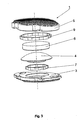
- Device 1 comprises a central axis 2, a first and a second apposition plate 3;5, a first and a second joint component 4;6, a first and second intermediate means 7;9.
- central axis 2 lies essentially parallel to a longitudinal axis of the patient's vertebra.
- First and second apposition plate 3;5 are disposed transversely to central axis 2.
- First and second joint components 4;6 are located between said first and second apposition plates 3;5. Together, first and second joint components 4;6 form a ball-joint and are mutually connectable in a ball-joint like manner.
- First intermediate means 7 is disposed between first apposition plate 3 and first joint component 4.
- Second intermediate means 9 is disposed between second apposition plate 5 and second joint component 6.
- First and second apposition plate 3;5 can be made of titanium or a titanium alloy.
- First and second joint component 4;6 can be made of a ceramic.
- the first and second intermediate means 7;9 can be made of an elastic materials, such as, for example a rubber or other type of polymer (e.g., PEEK).
- Said first apposition plate 3 comprises a first contact surface 31 and a first intermediate surface 32.
- said second apposition plate 5 comprises a second contact surface 51 and a second intermediate surface 52. Both contact surfaces 31;51 as well as both intermediate surfaces 32;52 are arranged transversely to said central axis 2.
- Said first and second apposition plates are arranged relative to each other in a manner that the first and second intermediate surface 32;52 are turned to each other and the first and second contact surfaces 31;51, which is apt to abut the adjacent vertebral bodies, are turned away from each other.
- said first and second apposition plates 3;5 each are provided with a three-dimensional structuring having a form of e.g., spikes and allowing an anchorage of said first and second apposition plates 3;5 in the adjacent vertebral bodies.
- Said first joint component 4 has a spherical convex sliding surface 41 being arranged concentrically to said central axis 2 and oppositely a first end portion 42 connected to said first apposition plate 3.
- Said second joint component 6 is provided with a spherical concave sliding surface 61 ( fig. 2 ) being slideably arranged on said convex sliding surface 41 and opposite to said concave sliding surface 61 a second end portion 62 connected to said second apposition plate 5. In this manner, the mutual arrangement of concave sliding surface 61 and convex sliding surface 41 provide device 1 with ball-joint like movement.
- Said first joint component 4 comprises circular cylindrical projection 43 being coaxial to the central axis 2 and being disposed at said first end portion 42 of said first joint component 4, whereby said first apposition plate 3 comprises the first recess 33 penetrating from said first intermediate surface 32 into said first apposition plate 3.
- said circular cylindrical projection 43 may be inserted into the first recess 33 such said circular cylindrical projection 43 and said first recess 33 forming a first attachment zone 10 ( fig. 2 ).
- said second joint component 6 has a circular cylindrical second end portion 62 that may be inserted into the second recess 53 penetrating from said second intermediate surface 52 into said second apposition plate 5 such said second end portion 62 and said second recess 53 forming a second attachment zone 100.
- each of said first and second apposition plates 3;5 is connected to the corresponding joint component 4;6 by a plug-socket connection, whereby the connection between the apposition plates 3;5 and the corresponding joint components (4;6) is clearance-free (i.e. no space between the apposition plates 3;5 and the corresponding joint components (4;6) is left to avoid free motion between them).
- Said first intermediate means 7 is configured as a ring radially disposed between said circular cylindrical projection 43 and said first recess 33, whereby said circular cylindrical projection 43 is pressed into the central bore 71 of said first intermediate means 7.
- the peripheral surface 72 of said first intermediate means 7 comprises a circular lip 73 forming a snap-fit with a circular undercut 11 at the bottom of said first recess 33.
- Adjacent to said first intermediate surface 32 of said first apposition plate 3 said first recess 33 has a diametrically enlarged section apt to press-fittingly receive a first flange 75 arranged at the top surface 76 of said first intermediate means 7.
- said second intermediate means 9 is configured as a ring radially disposed between said circular second end portion 62 and said second recess 63, whereby said circular second end portion 62 is pressed into the central bore 91 of said second intermediate means 9.
- the peripheral surface 92 of said second intermediate means 9 comprises a circular lip 93 forming a snap-fit with a circular undercut 111 at the bottom of said second recess 53.
- Adjacent to said second intermediate surface 52 of said second apposition plate 5 said second recess 53 has an diametrically enlarged section apt to press-fittingly receive a second flange 95 arranged at the bottom surface 96 of said second intermediate means 9.
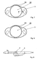
- Figs. 3 - 5 show a further embodiment of the total disc replacement device 1, whereby the intermediate means 7;9 are designed as a spring-like element.
- the embodiment according to figs.1 and 2 comprising a cylindrically shaped intermediate means 7;9 the embodiment according to fig. 3 does not require a circular lip forming a positive fit, but allows a frictional fit or connection between the intermediate means 7;9 and the corresponding apposition plates 3;5.
- Fig. 5 shows the intermediate means 7 being frictionally locked in the first recess 33 of the first apposition plate 3.
- the intermediate means 7;9 acting as a spring are plastically or elastically deformed and are clamped over the first and second attachment zones 10;100 with a press fit ( fig 4 ).
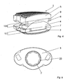
- Fig. 6 shows a further embodiment of the total disc replacement device 1, whereby the intermediate means and the corresponding apposition plates consist of one piece and the intermediate means are designed as a plurality of projections 50 formed in a T-shape configuration and being disposed on the periphery of the first and second recess 33;53.
- Fig. 7 shows a top view on the first apposition member 3 of the total disc replacement device according to fig. 6 with the first recess 33 being provided with T-shaped projections 50 on the periphery of said recess 33.
- Fig. 8 shows a top view of a further embodiment of the first apposition member of the total disc replacement device with the intermediate means and the first apposition plate 3 consisting of one piece, whereby the intermediate means are preformed as a plurality of L-shaped projections 50.
- Fig. 9 shows a cross-section through the first apposition plate 3 of a further embodiment of the total disc replacement device 1, whereby the height H of the intermediate means 7 is smaller then the height L of the attachment zone 10.
Claims (29)
- Dispositif de remplacement total d'un disque (1) comportant un axe central (2) et comprenant:A) une première et une seconde plaques d'apposition (3 ; 5) ;B) un premier et un second éléments de joint (4 ; 6) agencés mutuellement suivant une configuration de type joint à rotule et placés entre lesdites première et seconde plaques d'apposition (3 ; 5) ; etC) des moyens intermédiaires (7, 9), dans lequel au moins un moyen intermédiaire (7) est disposé entre la première plaque d'apposition (3) et le premier élément de joint (4) de telle manière que le premier élément de joint (4) ne puisse pas se déplacer librement par rapport à la première plaque d'apposition (3) dans des conditions d'absence de charge, mais de telle sorte qu'un déplacement limité du premier élément de joint (4) par rapport à la première plaque d'apposition (3) transversale à l'axe central (2) soit possible sous charge ;D) l'un au moins desdits moyens intermédiaires (7 ; 9) étant raccordé à la plaque d'apposition correspondante (3 ; 5) au moyen d'un ajustement par pression ou par l'intermédiaire d'un ajustement par encliquetage ;
et caractérisé en ce queE) l'un au moins desdits moyens intermédiaires (7 ; 9) est raccordé au joint correspondant (4 ; 6) au moyen d'un ajustement par pression ou au moyen d'un ajustement par encliquetage. - Dispositif (1) selon la revendication 1, dans lequel le raccordement entre la plaque d'apposition et l'élément de joint est dépourvu de jeu.
- Dispositif (1) selon la revendication 1 ou 2 comportant, de plus, des seconds moyens intermédiaires (9) disposés entre la seconde plaque d'apposition (5) et le second élément de joint (6).
- Dispositif (1) selon l'une des revendications 1 à 3, dans lequel lesdits moyens intermédiaire (7) sont déformables élastiquement.
- Dispositif (1) selon l'une des revendications 1 à 3, dans lequel lesdits moyens intermédiaires (7) sont déformables plastiquement.
- Dispositif (1) selon l'une des revendications 1 à 5, dans lequel l'ajustement par pression d'au moins l'un des moyens intermédiaires (7 ; 9) à l'intérieur de la plaque d'apposition adjacente (3 ; 5) ou à l'intérieur de l'élément de joint adjacent (4 ; 6) peut être obtenu par une déformation élastique des moyens intermédiaires (7 ; 9).
- Dispositif (1) selon l'une des revendications 1 à 6, dans lequel l'ajustement par pression d'au moins l'un des moyens intermédiaires (7, 9) à l'intérieur de la plaque d'apposition adjacente (3 ; 5) ou à l'intérieur de l'élément de joint adjacent (4 ; 6) peut être obtenu par une déformation plastique des moyens intermédiaires (7 ; 9).
- Dispositif (1) selon l'une des revendications 1 à 7, dans lequel l'une au moins des plaques d'apposition (3 ; 5) est connectée à l'élément de joint correspondant (4 ; 6) par un raccord à emboîtement de fiches, de telle sorte qu'au moins une partie de la plaque d'apposition (3 ; 5) et au moins une partie de l'élément de joint correspondant (4 ; 6) se superposent l'une l'autre de façon coaxiale à l'axe central (2) et constituent une zone de fixation (10 ; 11).
- Dispositif (1) selon la revendication 8, dans lequel les moyens intermédiaires (7 ; 9) sont disposés entre la plaque d'apposition (3 ; 5) et l'élément de joint correspondant (4 ; 6) seulement à l'intérieur de la zone de fixation (10 ; 11), de préférence à l'intérieur de la zone de fixation tout entière (10;11).
- Dispositif (1) selon l'une des revendications 1 à 9, dans lequel le module de Young du matériau des moyens intermédiaires (7 ; 9) est plus petit que celui de la plaque d'apposition adjacente (3 ; 5).
- Dispositif (1) selon l'une des revendications 1 à 10, dans lequel le module de Young du matériau des moyens intermédiaires (7 ; 9) est inférieur à celui de l'élément de joint adjacent (4 ; 6).
- Dispositif (1) selon l'une des revendications 1 à 11, dans lequel les moyens intermédiaires (7 ; 9) sont constitués du matériau qui peut être sélectionné dans le groupe constitué de PEEK, PEKK ou d'autres membres de la PEAK famille.
- Dispositif (1) selon l'une des revendications 1 à 12, dans lequel au moins l'une des plaques d'apposition (3 ; 5) est constituée du matériau qui peut être sélectionné dans le groupe constitué du titane et de ses alliages, du CoCrMo ou de l'acier inoxydable.
- Dispositif (1) selon l'une des revendications 1 à 13, dans lequel au moins l'un des éléments de joint (4 ; 6) est constitué du matériau qui peut être sélectionné dans le groupe constitué de céramique, de préférence de l'oxyde d'aluminium, de titanate d'aluminium, de céramique de silicate et d'oxyde de zirconium, ou dans le groupe constitué de CoCrMo ou d'alliages de CoCrMoC.
- Dispositif (1) selon l'une des revendications 1 à 14, dans lequel lesdites plaques d'apposition (3 ; 5) et lesdits éléments de joint adjacents (4 ; 6) sont constitués du même matériau.
- Dispositif (1) selon l'une des revendications 1 à 15 dans lequel lesdits moyens intermédiaires (7 ; 9) présentent une configuration essentiellement cylindrique.
- Dispositif (1) selon la revendication 16, dans lequel les moyens intermédiaires (7 ; 9) présentent une configuration essentiellement cylindrique - circulaire.
- Dispositif (1) selon l'une des revendications 1 à 3 et 8 à 17, dans lequel au moins l'un des moyens intermédiaires (7 ; 9) est constitué d'un matériau à mémoire.
- Dispositif (1) selon l'une des revendications 1 à 18, dans lequel lesdites plaques d'apposition (3 ; 5) ou lesdits éléments de joint (4 ; 6) sont dotés d'une lèvre (73 ; 93) et dans lequel lesdits moyens intermédiaires (7; 9) sont dotés de découpes correspondantes (11 ; 111) de façon à former un ajustement par encliquetage.
- Dispositif (1) selon l'une des revendications 1 à 18, dans lequel lesdites plaques d'apposition (3 ; 5) ou lesdits éléments de joint (4 ; 6) sont pourvus de découpes (11 ; 111) et lesdits moyens intermédiaires (7 ; 9) sont dotés d'une lèvre correspondante (73 ; 93) de façon à former un ajustement par encliquetage.
- Dispositif (1) selon l'une des revendications 1 à 17, dans lequel les moyens intermédiaires (7 ; 9) présentent une configuration de ressort qui est nervuré de façon transverse à l'axe central (2).
- Dispositif (1) selon l'une des revendications 8 à 21, dans lequel la zone de fixation (10) présente une hauteur L comprise entre 1,5 mm et 9 mm mesurée parallèlement à l'axe central (2).
- Dispositif (1) selon l'une des revendications 1 à 22, dans lequel lesdits moyens intermédiaires (7 ; 9) présentent une hauteur H comprise entre 0,7 mm et 6,0 mm mesurée parallèlement à l'axe central (2).
- Dispositif (1) selon l'une des revendications 1 à 23, dans lequel lesdits moyens intermédiaires (7 ; 9) présentent un volume minimal de 60 mm3.
- Dispositif (1) selon l'une des revendications 1 à 24, dans lequel lesdits moyens intermédiaires (7 ; 9) et la plaque d'apposition correspondante (3 ; 5) sont constitués d'une seule pièce.
- Dispositif (1) selon l'une des revendications 1 à 25, dans lequel au moins l'un desdits moyens intermédiaires (7 ; 9) et l'élément de joint correspondant (4 ; 6) est constitué en une seule pièce.
- Dispositif (1) selon l'une des revendications 25 ou 26, dans lequel les moyens intermédiaires sont conçus sous la forme d'une pluralité de parties en saillie (50).
- Dispositif (1) selon l'une de la revendication 27, dans lequel les parties en saillie sont configurées en forme de T.
- Dispositif (1) selon l'une de la revendication 27, dans lequel les parties en saillie sont configurées en forme de L.
Applications Claiming Priority (1)
| Application Number | Priority Date | Filing Date | Title |
|---|---|---|---|
| PCT/CH2006/000454 WO2008022471A1 (fr) | 2006-08-22 | 2006-08-22 | dispositif de remplacement total d'un disque |
Publications (2)
| Publication Number | Publication Date |
|---|---|
| EP2073762A1 EP2073762A1 (fr) | 2009-07-01 |
| EP2073762B1 true EP2073762B1 (fr) | 2011-04-06 |
Family
ID=37909554
Family Applications (1)
| Application Number | Title | Priority Date | Filing Date |
|---|---|---|---|
| EP06775148A Active EP2073762B1 (fr) | 2006-08-22 | 2006-08-22 | Dispositif de remplacement total d'un disque |
Country Status (6)
| Country | Link |
|---|---|
| US (1) | US8679181B2 (fr) |
| EP (1) | EP2073762B1 (fr) |
| AT (1) | ATE504267T1 (fr) |
| DE (1) | DE602006021239D1 (fr) |
| TW (1) | TW200820955A (fr) |
| WO (1) | WO2008022471A1 (fr) |
Families Citing this family (14)
| Publication number | Priority date | Publication date | Assignee | Title |
|---|---|---|---|---|
| ES2358494B1 (es) * | 2008-04-29 | 2012-03-27 | Desarrollo E Innovacion De Implantes Quirurgicos San Andres, S.L. | Prótesis cervical flexible. |
| DE102009011648A1 (de) * | 2009-03-04 | 2010-09-09 | Advanced Medical Technologies Ag | Implantatsystem mit Auflageelementen |
| EP2456374A1 (fr) * | 2009-08-10 | 2012-05-30 | OsteoMed LLC | Implants de fusion de processus épineux |
| US8998991B2 (en) * | 2011-02-23 | 2015-04-07 | Globus Medical, Inc. | Six degree spine stabilization devices and methods |
| US9017410B2 (en) | 2011-10-26 | 2015-04-28 | Globus Medical, Inc. | Artificial discs |
| US20140012382A1 (en) * | 2012-07-06 | 2014-01-09 | TrueMotion Spine, Inc. | Shock absorbing, total disc replacement prosthetic |
| US9198770B2 (en) | 2013-07-31 | 2015-12-01 | Globus Medical, Inc. | Artificial disc devices and related methods of use |
| CN105310758B (zh) * | 2015-03-18 | 2017-08-01 | 周军 | 一种椎间盘稳定器及其使用方法 |
| US10874521B2 (en) | 2017-11-07 | 2020-12-29 | Uki Llc | Artificial intervertebral implant |
| US10258482B1 (en) | 2017-11-07 | 2019-04-16 | Uki Llc | Artificial intervertebral implant |
| CN108969157B (zh) * | 2018-07-27 | 2021-07-09 | 深圳清华大学研究院 | 高仿生椎间运动保留装置 |
| CN108969158B (zh) * | 2018-07-27 | 2021-07-09 | 深圳清华大学研究院 | 一种椎间运动保留装置及其引导式植入器械和植入方法 |
| US11197765B2 (en) | 2019-12-04 | 2021-12-14 | Robert S. Bray, Jr. | Artificial disc replacement device |
| US11839554B2 (en) | 2020-01-23 | 2023-12-12 | Robert S. Bray, Jr. | Method of implanting an artificial disc replacement device |
Family Cites Families (57)
| Publication number | Priority date | Publication date | Assignee | Title |
|---|---|---|---|---|
| CH517041A (de) * | 1971-02-27 | 1971-12-31 | Rieter Ag Maschf | Spulentragvorrichtung mit einer Vorrichtung zum Festhalten und Zentrieren von Hülsen |
| DE2845716C2 (de) * | 1978-10-20 | 1985-08-01 | Volkswagenwerk Ag, 3180 Wolfsburg | Thermisch hoch beanspruchbare Verbindung |
| US5392693A (en) * | 1994-03-02 | 1995-02-28 | Caterpillar Inc. | Piston assembly for a fluid translating device |
| CN1298288A (zh) * | 1998-04-08 | 2001-06-06 | Imz制造和牙齿工艺贸易有限公司 | 植入骨内的单齿植入件 |
| US6964686B2 (en) * | 1999-05-17 | 2005-11-15 | Vanderbilt University | Intervertebral disc replacement prosthesis |
| MXPA01013413A (es) * | 1999-07-02 | 2003-09-04 | Spine Solutions Inc | Implante intervertebral. |
| AU783205C (en) * | 2000-03-15 | 2006-08-17 | Depuy Orthopaedics, Inc. | Prosthetic cup assembly which includes components possessing self-locking taper |
| US7563285B2 (en) * | 2001-07-16 | 2009-07-21 | Spinecore, Inc. | Artificial intervertebral disc utilizing a ball joint coupling |
| US6989032B2 (en) * | 2001-07-16 | 2006-01-24 | Spinecore, Inc. | Artificial intervertebral disc |
| US7597715B2 (en) * | 2005-04-21 | 2009-10-06 | Biomet Manufacturing Corp. | Method and apparatus for use of porous implants |
| US6746451B2 (en) * | 2001-06-01 | 2004-06-08 | Lance M. Middleton | Tissue cavitation device and method |
| DE50114038D1 (de) * | 2001-08-24 | 2008-07-31 | Zimmer Gmbh | Künstliche Bandscheibe |
| WO2003032801A2 (fr) * | 2001-10-18 | 2003-04-24 | Third Millennium Engineering Llc | Disque intervertebral artificiel dote d'un element de restauration de force de rappel a ressort araignee |
| US7025787B2 (en) * | 2001-11-26 | 2006-04-11 | Sdgi Holdings, Inc. | Implantable joint prosthesis and associated instrumentation |
| US6916342B2 (en) * | 2002-04-01 | 2005-07-12 | Smith & Nephew, Inc. | Liner assembly for prosthetic components |
| US8696749B2 (en) * | 2002-04-25 | 2014-04-15 | Blackstone Medical, Inc. | Artificial intervertebral disc |
| US7001433B2 (en) * | 2002-05-23 | 2006-02-21 | Pioneer Laboratories, Inc. | Artificial intervertebral disc device |
| JP4456481B2 (ja) * | 2002-08-15 | 2010-04-28 | ガーバー,デイヴィッド | 制御された人工椎間板インプラント |
| DE60331089D1 (en) * | 2002-09-19 | 2010-03-11 | Villiers Malan De | Intervertebralprothese |
| US20040133278A1 (en) * | 2002-10-31 | 2004-07-08 | Marino James F. | Spinal disc implant |
| US7407513B2 (en) * | 2003-05-02 | 2008-08-05 | Smart Disc, Inc. | Artificial spinal disk |
| US7105024B2 (en) * | 2003-05-06 | 2006-09-12 | Aesculap Ii, Inc. | Artificial intervertebral disc |
| US20050143824A1 (en) * | 2003-05-06 | 2005-06-30 | Marc Richelsoph | Artificial intervertebral disc |
| GB0313472D0 (en) * | 2003-06-11 | 2003-07-16 | Weatherford Lamb | Tubing connector |
| BR0318406A (pt) * | 2003-07-22 | 2006-09-19 | Synthes Gmbh | implante intervertebral com meios de travamento temporário |
| US7153325B2 (en) * | 2003-08-01 | 2006-12-26 | Ultra-Kinetics, Inc. | Prosthetic intervertebral disc and methods for using the same |
| FR2858546B1 (fr) * | 2003-08-04 | 2006-04-28 | Spine Next Sa | Prothese de disque intervertebral |
| US20050038516A1 (en) | 2003-08-14 | 2005-02-17 | Mark Spoonamore | Intervertebral disk prosthesis and method |
| DE10339170B4 (de) | 2003-08-22 | 2009-10-15 | Aesculap Ag | Zwischenwirbelimplantat |
| US7040407B2 (en) * | 2003-09-05 | 2006-05-09 | Vetco Gray Inc. | Collet load shoulder |
| FR2864763B1 (fr) * | 2004-01-07 | 2006-11-24 | Scient X | Prothese discale pour vertebres |
| US7250060B2 (en) | 2004-01-27 | 2007-07-31 | Sdgi Holdings, Inc. | Hybrid intervertebral disc system |
| US7214244B2 (en) * | 2004-02-19 | 2007-05-08 | Spinecore, Inc. | Artificial intervertebral disc having an articulating joint |
| US7393361B2 (en) * | 2004-02-20 | 2008-07-01 | Spinecore, Inc. | Artificial intervertebral disc having a bored semispherical bearing with a compression locking post and retaining caps |
| US7485145B2 (en) * | 2004-02-23 | 2009-02-03 | Alphatec Spine, Incorporated | Artificial intervertebral disc assembly |
| US7491239B2 (en) * | 2005-02-23 | 2009-02-17 | Joint Synergy, Llc | Interior insert ball and dual socket joint |
| US7195644B2 (en) * | 2004-03-02 | 2007-03-27 | Joint Synergy, Llc | Ball and dual socket joint |
| CA2573340A1 (fr) * | 2004-07-09 | 2006-02-16 | Pioneer Laboratories, Inc. | Dispositif de reconstruction du squelette |
| FR2879436B1 (fr) * | 2004-12-22 | 2007-03-09 | Ldr Medical | Prothese de disque intervertebral |
| CH697330B1 (de) * | 2004-12-28 | 2008-08-29 | Synthes Gmbh | Zwischenwirbelprothese. |
| US7799080B2 (en) * | 2005-04-22 | 2010-09-21 | Doty Keith L | Spinal disc prosthesis and methods of use |
| FR2891135B1 (fr) * | 2005-09-23 | 2008-09-12 | Ldr Medical Sarl | Prothese de disque intervertebral |
| US7708777B2 (en) * | 2006-02-03 | 2010-05-04 | Depuy Spine, Inc. | Modular intervertebral disc replacements |
| US20070233251A1 (en) * | 2006-02-18 | 2007-10-04 | Abdou M S | Use of Magnetic Fields in Orthopedic Implants |
| US20070203580A1 (en) * | 2006-02-24 | 2007-08-30 | Paonan Biotech Co., Ltd. | Intervertebral filling |
| EP2001410B1 (fr) * | 2006-03-22 | 2016-12-28 | Ascension Orthopedics, Inc. | Implant prothétique et son procédé d'assemblage |
| US20070239283A1 (en) * | 2006-04-11 | 2007-10-11 | Berger Richard A | Acetabular cup conversion ring |
| US8308811B2 (en) * | 2006-04-11 | 2012-11-13 | Zimmer, Inc. | Acetabular cup conversion ring |
| US7794501B2 (en) * | 2006-04-27 | 2010-09-14 | Wasaw Orthopedic, Inc. | Expandable intervertebral spacers and methods of use |
| US20080021557A1 (en) * | 2006-07-24 | 2008-01-24 | Warsaw Orthopedic, Inc. | Spinal motion-preserving implants |
| US8070823B2 (en) * | 2006-11-07 | 2011-12-06 | Biomedflex Llc | Prosthetic ball-and-socket joint |
| WO2008067400A2 (fr) * | 2006-11-29 | 2008-06-05 | Ascension Orthopedics, Inc. | Implant d'articulation d'épaule |
| WO2008088777A2 (fr) * | 2007-01-12 | 2008-07-24 | Synthes Usa, Llc | Implant intervertébral modulaire |
| US8182534B2 (en) * | 2007-09-27 | 2012-05-22 | K2M, Inc. | Orthopedic device assembly with elements coupled by a retaining structure |
| US8662045B2 (en) * | 2009-08-03 | 2014-03-04 | GM Global Technology Operations LLC | Cylinder head assembly for an internal combustion engine |
| US20110100316A1 (en) * | 2009-11-05 | 2011-05-05 | Gm Global Technology Operations, Inc. | Cylinder Head Assembly For An Internal Combustion Engine and Method of Manufacture |
| US9220599B2 (en) * | 2010-08-24 | 2015-12-29 | Biomet Manufacturing, Llc | Acetabular cup having deformation resistant features |
-
2006
- 2006-08-22 AT AT06775148T patent/ATE504267T1/de not_active IP Right Cessation
- 2006-08-22 US US12/438,088 patent/US8679181B2/en active Active
- 2006-08-22 WO PCT/CH2006/000454 patent/WO2008022471A1/fr active Application Filing
- 2006-08-22 EP EP06775148A patent/EP2073762B1/fr active Active
- 2006-08-22 DE DE602006021239T patent/DE602006021239D1/de active Active
-
2007
- 2007-07-26 TW TW096127185A patent/TW200820955A/zh unknown
Also Published As
| Publication number | Publication date |
|---|---|
| EP2073762A1 (fr) | 2009-07-01 |
| WO2008022471A1 (fr) | 2008-02-28 |
| DE602006021239D1 (de) | 2011-05-19 |
| TW200820955A (en) | 2008-05-16 |
| US8679181B2 (en) | 2014-03-25 |
| ATE504267T1 (de) | 2011-04-15 |
| US20110054618A1 (en) | 2011-03-03 |
Similar Documents
| Publication | Publication Date | Title |
|---|---|---|
| EP2073762B1 (fr) | Dispositif de remplacement total d'un disque | |
| US8277508B2 (en) | Hybrid intervertebral disc system | |
| US7601174B2 (en) | Wear-resistant endoprosthetic devices | |
| US7537612B2 (en) | Lumbar composite nucleus | |
| US8920501B2 (en) | Implant system having at least three support elements | |
| EP1919404B1 (fr) | Dispositif médical orthopédique | |
| AU2006254502B2 (en) | Intervertebral disk implant | |
| US7048764B2 (en) | Artificial disc replacements with articulating components | |
| CA2518068C (fr) | Remplacement d'un disque cervical | |
| US7083651B2 (en) | Spinal implant | |
| US7491239B2 (en) | Interior insert ball and dual socket joint | |
| US8353964B2 (en) | Anatomic total disc replacement | |
| US20150032211A1 (en) | Flexible space holder | |
| US20060111783A1 (en) | Articulating spinal disc prosthetic | |
| WO2008073064A1 (fr) | Balle et articulation à rotule double | |
| KR20070032642A (ko) | 인공보철 추간원판 또는 인공의 척추골 | |
| WO2008094260A2 (fr) | Articulation à deux rotules concentriques à insertion de bille intérieure. | |
| US20060247777A1 (en) | Multiple bearing implant | |
| US8597354B2 (en) | Vertebral implant | |
| AU2005229466A1 (en) | Artificial intervertebral disk | |
| KR20210154533A (ko) | 인공 디스크 | |
| US20120109306A1 (en) | Spinal implant | |
| KR102355931B1 (ko) | 인공 디스크 및 그 제조방법 | |
| KR20220102828A (ko) | 인공 디스크 | |
| McTighe et al. | A NEW APPROACH TO BEARING SURFACES FOR TOTAL HIP ARTHROPLASTY |
Legal Events
| Date | Code | Title | Description |
|---|---|---|---|
| PUAI | Public reference made under article 153(3) epc to a published international application that has entered the european phase |
Free format text: ORIGINAL CODE: 0009012 |
|
| 17P | Request for examination filed |
Effective date: 20090221 |
|
| AK | Designated contracting states |
Kind code of ref document: A1 Designated state(s): AT BE BG CH CY CZ DE DK EE ES FI FR GB GR HU IE IS IT LI LT LU LV MC NL PL PT RO SE SI SK TR |
|
| AX | Request for extension of the european patent |
Extension state: AL BA HR MK RS |
|
| RIN1 | Information on inventor provided before grant (corrected) |
Inventor name: BUERKI, ROGER Inventor name: LECHMANN, BEAT |
|
| GRAP | Despatch of communication of intention to grant a patent |
Free format text: ORIGINAL CODE: EPIDOSNIGR1 |
|
| DAX | Request for extension of the european patent (deleted) | ||
| GRAS | Grant fee paid |
Free format text: ORIGINAL CODE: EPIDOSNIGR3 |
|
| GRAA | (expected) grant |
Free format text: ORIGINAL CODE: 0009210 |
|
| AK | Designated contracting states |
Kind code of ref document: B1 Designated state(s): AT BE BG CH CY CZ DE DK EE ES FI FR GB GR HU IE IS IT LI LT LU LV MC NL PL PT RO SE SI SK TR |
|
| REG | Reference to a national code |
Ref country code: GB Ref legal event code: FG4D |
|
| REG | Reference to a national code |
Ref country code: CH Ref legal event code: NV Representative=s name: DR. LUSUARDI AG Ref country code: CH Ref legal event code: EP |
|
| REG | Reference to a national code |
Ref country code: IE Ref legal event code: FG4D |
|
| REF | Corresponds to: |
Ref document number: 602006021239 Country of ref document: DE Date of ref document: 20110519 Kind code of ref document: P |
|
| REG | Reference to a national code |
Ref country code: DE Ref legal event code: R096 Ref document number: 602006021239 Country of ref document: DE Effective date: 20110519 |
|
| REG | Reference to a national code |
Ref country code: NL Ref legal event code: VDEP Effective date: 20110406 |
|
| PG25 | Lapsed in a contracting state [announced via postgrant information from national office to epo] |
Ref country code: SI Free format text: LAPSE BECAUSE OF FAILURE TO SUBMIT A TRANSLATION OF THE DESCRIPTION OR TO PAY THE FEE WITHIN THE PRESCRIBED TIME-LIMIT Effective date: 20110406 |
|
| LTIE | Lt: invalidation of european patent or patent extension |
Effective date: 20110406 |
|
| PG25 | Lapsed in a contracting state [announced via postgrant information from national office to epo] |
Ref country code: SE Free format text: LAPSE BECAUSE OF FAILURE TO SUBMIT A TRANSLATION OF THE DESCRIPTION OR TO PAY THE FEE WITHIN THE PRESCRIBED TIME-LIMIT Effective date: 20110406 Ref country code: PT Free format text: LAPSE BECAUSE OF FAILURE TO SUBMIT A TRANSLATION OF THE DESCRIPTION OR TO PAY THE FEE WITHIN THE PRESCRIBED TIME-LIMIT Effective date: 20110808 Ref country code: LT Free format text: LAPSE BECAUSE OF FAILURE TO SUBMIT A TRANSLATION OF THE DESCRIPTION OR TO PAY THE FEE WITHIN THE PRESCRIBED TIME-LIMIT Effective date: 20110406 |
|
| PG25 | Lapsed in a contracting state [announced via postgrant information from national office to epo] |
Ref country code: IS Free format text: LAPSE BECAUSE OF FAILURE TO SUBMIT A TRANSLATION OF THE DESCRIPTION OR TO PAY THE FEE WITHIN THE PRESCRIBED TIME-LIMIT Effective date: 20110806 Ref country code: AT Free format text: LAPSE BECAUSE OF FAILURE TO SUBMIT A TRANSLATION OF THE DESCRIPTION OR TO PAY THE FEE WITHIN THE PRESCRIBED TIME-LIMIT Effective date: 20110406 Ref country code: ES Free format text: LAPSE BECAUSE OF FAILURE TO SUBMIT A TRANSLATION OF THE DESCRIPTION OR TO PAY THE FEE WITHIN THE PRESCRIBED TIME-LIMIT Effective date: 20110717 Ref country code: CY Free format text: LAPSE BECAUSE OF FAILURE TO SUBMIT A TRANSLATION OF THE DESCRIPTION OR TO PAY THE FEE WITHIN THE PRESCRIBED TIME-LIMIT Effective date: 20110406 Ref country code: LV Free format text: LAPSE BECAUSE OF FAILURE TO SUBMIT A TRANSLATION OF THE DESCRIPTION OR TO PAY THE FEE WITHIN THE PRESCRIBED TIME-LIMIT Effective date: 20110406 Ref country code: BE Free format text: LAPSE BECAUSE OF FAILURE TO SUBMIT A TRANSLATION OF THE DESCRIPTION OR TO PAY THE FEE WITHIN THE PRESCRIBED TIME-LIMIT Effective date: 20110406 Ref country code: FI Free format text: LAPSE BECAUSE OF FAILURE TO SUBMIT A TRANSLATION OF THE DESCRIPTION OR TO PAY THE FEE WITHIN THE PRESCRIBED TIME-LIMIT Effective date: 20110406 Ref country code: GR Free format text: LAPSE BECAUSE OF FAILURE TO SUBMIT A TRANSLATION OF THE DESCRIPTION OR TO PAY THE FEE WITHIN THE PRESCRIBED TIME-LIMIT Effective date: 20110707 |
|
| PG25 | Lapsed in a contracting state [announced via postgrant information from national office to epo] |
Ref country code: NL Free format text: LAPSE BECAUSE OF FAILURE TO SUBMIT A TRANSLATION OF THE DESCRIPTION OR TO PAY THE FEE WITHIN THE PRESCRIBED TIME-LIMIT Effective date: 20110406 |
|
| PG25 | Lapsed in a contracting state [announced via postgrant information from national office to epo] |
Ref country code: CZ Free format text: LAPSE BECAUSE OF FAILURE TO SUBMIT A TRANSLATION OF THE DESCRIPTION OR TO PAY THE FEE WITHIN THE PRESCRIBED TIME-LIMIT Effective date: 20110406 Ref country code: EE Free format text: LAPSE BECAUSE OF FAILURE TO SUBMIT A TRANSLATION OF THE DESCRIPTION OR TO PAY THE FEE WITHIN THE PRESCRIBED TIME-LIMIT Effective date: 20110406 |
|
| PLBE | No opposition filed within time limit |
Free format text: ORIGINAL CODE: 0009261 |
|
| STAA | Information on the status of an ep patent application or granted ep patent |
Free format text: STATUS: NO OPPOSITION FILED WITHIN TIME LIMIT |
|
| PG25 | Lapsed in a contracting state [announced via postgrant information from national office to epo] |
Ref country code: SK Free format text: LAPSE BECAUSE OF FAILURE TO SUBMIT A TRANSLATION OF THE DESCRIPTION OR TO PAY THE FEE WITHIN THE PRESCRIBED TIME-LIMIT Effective date: 20110406 Ref country code: PL Free format text: LAPSE BECAUSE OF FAILURE TO SUBMIT A TRANSLATION OF THE DESCRIPTION OR TO PAY THE FEE WITHIN THE PRESCRIBED TIME-LIMIT Effective date: 20110406 Ref country code: DK Free format text: LAPSE BECAUSE OF FAILURE TO SUBMIT A TRANSLATION OF THE DESCRIPTION OR TO PAY THE FEE WITHIN THE PRESCRIBED TIME-LIMIT Effective date: 20110406 Ref country code: RO Free format text: LAPSE BECAUSE OF FAILURE TO SUBMIT A TRANSLATION OF THE DESCRIPTION OR TO PAY THE FEE WITHIN THE PRESCRIBED TIME-LIMIT Effective date: 20110406 |
|
| 26N | No opposition filed |
Effective date: 20120110 |
|
| PG25 | Lapsed in a contracting state [announced via postgrant information from national office to epo] |
Ref country code: MC Free format text: LAPSE BECAUSE OF NON-PAYMENT OF DUE FEES Effective date: 20110831 |
|
| REG | Reference to a national code |
Ref country code: DE Ref legal event code: R097 Ref document number: 602006021239 Country of ref document: DE Effective date: 20120110 |
|
| REG | Reference to a national code |
Ref country code: IE Ref legal event code: MM4A |
|
| PG25 | Lapsed in a contracting state [announced via postgrant information from national office to epo] |
Ref country code: IE Free format text: LAPSE BECAUSE OF NON-PAYMENT OF DUE FEES Effective date: 20110822 |
|
| PG25 | Lapsed in a contracting state [announced via postgrant information from national office to epo] |
Ref country code: LU Free format text: LAPSE BECAUSE OF NON-PAYMENT OF DUE FEES Effective date: 20110822 |
|
| PG25 | Lapsed in a contracting state [announced via postgrant information from national office to epo] |
Ref country code: BG Free format text: LAPSE BECAUSE OF FAILURE TO SUBMIT A TRANSLATION OF THE DESCRIPTION OR TO PAY THE FEE WITHIN THE PRESCRIBED TIME-LIMIT Effective date: 20110706 |
|
| PG25 | Lapsed in a contracting state [announced via postgrant information from national office to epo] |
Ref country code: TR Free format text: LAPSE BECAUSE OF FAILURE TO SUBMIT A TRANSLATION OF THE DESCRIPTION OR TO PAY THE FEE WITHIN THE PRESCRIBED TIME-LIMIT Effective date: 20110406 |
|
| PG25 | Lapsed in a contracting state [announced via postgrant information from national office to epo] |
Ref country code: HU Free format text: LAPSE BECAUSE OF FAILURE TO SUBMIT A TRANSLATION OF THE DESCRIPTION OR TO PAY THE FEE WITHIN THE PRESCRIBED TIME-LIMIT Effective date: 20110406 |
|
| REG | Reference to a national code |
Ref country code: FR Ref legal event code: PLFP Year of fee payment: 11 |
|
| REG | Reference to a national code |
Ref country code: FR Ref legal event code: PLFP Year of fee payment: 12 |
|
| REG | Reference to a national code |
Ref country code: FR Ref legal event code: PLFP Year of fee payment: 13 |
|
| PGFP | Annual fee paid to national office [announced via postgrant information from national office to epo] |
Ref country code: IT Payment date: 20200713 Year of fee payment: 15 |
|
| PG25 | Lapsed in a contracting state [announced via postgrant information from national office to epo] |
Ref country code: IT Free format text: LAPSE BECAUSE OF NON-PAYMENT OF DUE FEES Effective date: 20210822 |
|
| PGFP | Annual fee paid to national office [announced via postgrant information from national office to epo] |
Ref country code: GB Payment date: 20230629 Year of fee payment: 18 Ref country code: CH Payment date: 20230902 Year of fee payment: 18 |
|
| PGFP | Annual fee paid to national office [announced via postgrant information from national office to epo] |
Ref country code: FR Payment date: 20230703 Year of fee payment: 18 Ref country code: DE Payment date: 20230703 Year of fee payment: 18 |