EP2073537B1 - Projection display - Google Patents
Projection display Download PDFInfo
- Publication number
- EP2073537B1 EP2073537B1 EP09003308A EP09003308A EP2073537B1 EP 2073537 B1 EP2073537 B1 EP 2073537B1 EP 09003308 A EP09003308 A EP 09003308A EP 09003308 A EP09003308 A EP 09003308A EP 2073537 B1 EP2073537 B1 EP 2073537B1
- Authority
- EP
- European Patent Office
- Prior art keywords
- light
- shielding bodies
- light shielding
- lens array
- lens
- Prior art date
- Legal status (The legal status is an assumption and is not a legal conclusion. Google has not performed a legal analysis and makes no representation as to the accuracy of the status listed.)
- Active
Links
Images


Classifications
-
- H—ELECTRICITY
- H04—ELECTRIC COMMUNICATION TECHNIQUE
- H04N—PICTORIAL COMMUNICATION, e.g. TELEVISION
- H04N9/00—Details of colour television systems
- H04N9/12—Picture reproducers
- H04N9/31—Projection devices for colour picture display, e.g. using electronic spatial light modulators [ESLM]
- H04N9/3141—Constructional details thereof
- H04N9/315—Modulator illumination systems
- H04N9/3152—Modulator illumination systems for shaping the light beam
Definitions
- the present invention relates to a projection display with a light-amount control mechanism for adjusting the amount of light applied to a light valve responsive to a video signal.
- a projection display is apt to have difficulty in ensuring high contrast because dark projected images displayed are not sufficiently dark due to leakage of light from various optical elements in an optical system such as a guide optical system and a projection lens and due to stray light (unnecessary light) caused by the optical elements.
- an optical system such as a guide optical system and a projection lens
- stray light unnecessary light
- insufficient darkness of dark projected images on display gives to a viewer the impression of low contrast.
- liquid crystal light valves although the liquid crystal light valves block transmitted light in response to the polarization property of light, complete blocking of transmitted light is difficult and there is also a limit in counteractive actions taken by video signal processing so that an improvement in contrast is required.
- a flat light shielding plate is provided between first and second lens arrays and is turned in response to a video signal to control the amount of light applied to a light valve and thereby to improve the contrast of a projected image on a screen or the like (for example, see WO2005/026835 ).
- US 2006/0050249 A1 describes a projector apparatus comprising a light amount control apparatus which has light amount control plates formed by punching a thin metal plate. Said light amount control apparatus is configured to provide opening uniform from a center of the light path to the right and left sides.
- An object of the invention is to provide a projection display that achieves continuous light amount control with ease and without causing unevenness of illumination of light applied to a light valve responsive to a video signal, thereby allowing constant image display with satisfactory contrast.
- Fig. 1 is a block diagram of an illumination optical system 1 in a projection display according to a first example of the invention.
- the illumination optical system 1 includes an integrator lens 4 between a light source system 3 and a light valve 2, a polarization conversion element 5, a condensing lens 6, a field lens 7, and a polarizing plate 8.
- the projection display according to the first example of the invention further includes a projection lens (not shown) for projecting light emitted from the light valve 2 onto a screen.
- the light valve 2 is provided on each of the optical paths of R, G, and B, and the illumination optical system 1 shown in Fig. 1 is a representative example of any one of those optical paths of R, G, and B.
- the light valve 2 is a liquid crystal light valve, but in the case of using lens arrays, it may be other display devices such as a digital micro-mirror device (DMD) and a reflection liquid crystal display device.
- DMD digital micro-mirror device
- the light source system 3 is configured to apply light to the light valve 2 and includes a light source 3a and a reflecting mirror 3b that reflects light emitted from the light source 3a to irradiate the integrator lens 4.
- the light source 3a is in general a high-pressure mercury lamp, a halogen lamp, or a xenon lamp, but it may be any other light-emitting devices such as a light emitting diode (LED), a laser, and an electrodeless discharge lamp.
- the reflecting mirror 3b is formed in an elliptical plane or a parabolic plane, but it may be of any shape and any configuration and is not limited to those described as long as light can be concentrated on the polarization conversion element 5.
- the reflecting mirror 3b should be formed in the shape of a parabola; or if the reflecting mirror 3b is formed in the shape of an ellipse, a concave lens should be provided between the light source system 3 and the integrator lens 4 (see Fig. 32 ).
- the integrator lens 4 is provided on an optical path between the light source system 3 and the light valve 2 and is configured to make uniform the illumination distribution of light applied from the light source system 3 to the light valve 2.
- the integrator lens 4 includes a first lens array 4a and a second lens array 4b spaced apart from the first lens array 4a.
- the first lens array 4a and the second lens array 4b each are an array of a plurality of convex lenses.
- the convex lenses in the first lens array 4a and the convex lenses in the second lens array 4b correspond to each other and are located to face each other.
- Fig. 2 is a block diagram of the polarization conversion element 5 according to the first preferred embodiment of the invention. As shown in Fig.
- the polarization conversion element 5 includes a plurality of polarization separation films 5a inclined (e.g., 45 degrees) toward the direction of the optical axis C (the z direction); a plurality of reflection films 5b provided between the polarization separation films 5a and inclined (e.g., 45 degrees) toward the direction of the optical axis C (the z direction); and ⁇ /2 phase-difference plates 5c provided in a plane of the polarization conversion element 5 on the side of the light valve 2 and in positions where light passing through the polarization separation films 5a are applied.
- Light incident on the polarization conversion element 5 is separated into s-polarized light and p-polarized light by the polarization separation films 5a.
- the p-polarized light is transmitted through the polarization separation films 5a, is converted into s-polarized light by the ⁇ /2 phase-difference plates 5c, and then is emitted from the polarization conversion element 5.
- the s-polarized light is reflected off the polarization separation films 5a and off the reflection films 5b and then is emitted from the polarization conversion element 5. Accordingly, the outgoing beams from the polarization conversion element 5 are almost all s-polarized light.
- the light-amount control system 9 (light-amount control mechanism) is provided on the optical path and includes a turning mechanism 9a which includes a pair of light shielding bodies that turn like a double door in order to adjust the amount of light applied from the light source system 3 to the light valve 2.
- the light-amount control system 9 includes the turning mechanism 9a provided between the first lens array 4a and the second lens array 4b; a signal detector 9b detecting a video signal fed to the light valve 2 and calculating, based on the result of detection, the relative percentage of the amount of light applied to the light valve 2; and a turning controller 9c controlling the turning of the turning mechanism 9a based on the relative percentage of the amount of light calculated by the signal detector 9b.
- the turning mechanism 9a includes light shielding bodies 9T and 9B that are bent into a V shape in a direction to reduce the amount of light (to block the light).
- the light shielding bodies 9T and 9B have at their tips cuts 9g that regulate passage of light.
- the cuts 9g may be of any shape such as a concave curve, a parabola, a semi-ellipse, and a triangle.
- a video signal represents 100% of the relative percentage of the amount of light
- control is performed based on 100% of the relative percentage of the amount of light with no light blocking by the turning mechanism 9a.
- the turning mechanism 9a blocks the light until the relative percentage of the amount of light becomes 20%, so that approximately a five-fold fine adjustment of the video signal is possible.
- darker black can be obtained as compared with the case where a video signal represents 0% of the relative percentage of the amount of light in which case no light blocking is provided.
- the transmittance of the light valve 2 is approximately constant, reducing the amount of light applied to the light valve 2 using the turning mechanism 9a makes it possible to darken a projected image on a screen, thereby achieving improvement in contrast.
- Fig. 4A shows a 15-degree turning of the light shielding bodies 9T and 9B of Fig. 3A
- Fig. 4B shows a 15-degree turning of the light shielding bodies 9T and 9B of Fig. 3B
- the amount of travel Zb in Fig. 4B is smaller than the amount of travel Za in Fig. 4A (Za > Zb), from which it can be found that the amount of travel of the light shielding bodies 9T and 9B in the y direction per turning angle is greater in Fig. 4B
- the light shielding bodies 9T and 9B in the shape as shown in Fig. 4B can provide illumination with 100% of the relative percentage of the amount of light at a smaller turning angle.
- Fig. 5 shows the relationship between the turning angle and the relative percentage of the amount of light in the cases where the turning mechanism 9a is in the shapes of Figs. 3A and 3B .
- the angles ⁇ T and ⁇ B in Fig. 3B shall be 20 degrees and the turning mechanism 9a in both Figs. 3A and 3B turns two degrees at a time.
- the turning angle of 0 degree refers to the condition that the light shielding bodies 9T and 9B are in completely closed positions, i.e., the light shielding bodies 9T and 9B are in the positions indicated by 41a in Fig. 4A and 41b in Fig. 4B , respectively.
- the curve 50 shows the simulation result for the turning mechanism 9a in the shape of Fig.
- the curve 51 shows the simulation result for the turning mechanism 9a in the shape of Fig. 3B .
- the curve 51 starts to rise earlier than the curve 50 with a low relative percentage of the amount of light and reaches 100% of the relative percentage of the amount of light at the turning angle of approximately 75 degrees.
- the shape of Fig. 3B allows highly responsive control as compared with the shape of Fig. 3A . It can also be seen from the curves 50 and 51 that, except where the relative percentage of the amount of light is low, the rate of change in the relative percentage of the amount of light with respect to the turning angle is approximately the same. From this, as will be described later with Fig.
- the relationship between the turning angle of the turning mechanism 9a and the relative percentage of the amount of light on the light valve 2, shown in the example of the invention, is for the case where input is a signal representing 100% of the relative percentage of the amount of light, so that only the property of the turning mechanism 9a is represented.
- Figs. 6A and 6B show the positions of the tips of the light shielding bodies 9T and 9B in the z direction when the relative percentage of the amount of light is 20% in Fig. 5 .
- the turning angle in the case of the shape of Fig. 3A is approximately 24 degrees, i.e., ⁇ 1 ⁇ 24
- the turning angle in the case of the shape of Fig. 3B is approximately 34 degrees, i.e., ⁇ 2 ⁇ 34.
- the angle ⁇ 3 in Fig. 6B is equal to ⁇ T and shall be 20 degrees.
- d1 be the length of the light shielding bodies 9T and 9B of Fig.
- d2 be the length of the light shielding bodies 9T and 9B of Fig. 6B from the turning axis to their bend
- d3 be the length of the light shielding bodies 9T and 9B of Fig. 6B from their bends to tips. Based on the conditions described above, the positions of the tips of the light shielding bodies 9T and 9B in the shape of Fig. 3B in the z direction can be calculated.
- the amounts of travel Zc and Zd of the light shielding bodies 9T and 9B in the z direction can be expressed by the following equations (1) and (2), respectively.
- Zc d ⁇ 1 ⁇ sin ⁇ ⁇ 1 ⁇ d ⁇ 1 ⁇ 0.41
- Zd d ⁇ 2 ⁇ sin ⁇ ⁇ 2 + d ⁇ 3 ⁇ sin ⁇ ⁇ 2 - ⁇ ⁇ 3 ⁇ d ⁇ 2 ⁇ 0.56 + d ⁇ 3 ⁇ 0.24
- d1 can be expressed by the following equation (3).
- d ⁇ 1 d ⁇ 2 ⁇ cos ⁇ ⁇ 3 + d ⁇ 3 ⁇ d ⁇ 2 ⁇ 0.94 + d ⁇ 3
- Zc can be expressed by the following equation (4), so that the condition Zc > Zd can be satisfied by equation (5).
- the shape of Fig. 3B can reduce unevenness of illumination as compared with the shape of Fig. 3A . Since the distance of travel of the tips of the light shielding bodies 9T and 9B is not the only cause of unevenness of illumination, the condition of equation (5) should preferably be satisfied but it is not a necessity.
- Fig. 7 shows the illumination distribution of light applied to the light valve 2 when the shape of Fig. 3B provides complete light blocking. In the case of complete light blocking, unevenness of illumination does not occur because light incident on the second lens array 4b is uniformly superimposed and applied onto the generally whole (area 7a) and around both x-direction end portions (areas 7b) of the light valve 2.
- the area 7a shows the illumination distribution of light applied from cells to the light valve 2 (area 30 in Fig. 3B ) when the opening of the cells in the second lens array 4b is approximately full open
- the areas 7b show the illumination distribution of light applied from cells to the light valve 2 (areas 31 in Fig. 3B ) when the opening of the cells in the second lens array 4b is approximately half opened.
- Fig. 8 shows the relationship between the turning angle and the relative percentage of the amount of light in the case where the light shielding bodies 9T and 9B with no bend have no cut. Simulation is conducted for every two degrees of the turning angle. It can be seen from the curve 80 that the rage of change in the relative percentage of the amount of light with respect to the turning angle is not continuous, and that the curve has four flat parts (8a, 8b, 8c, and 8d).
- Fig. 9 shows light source images in the vicinity of the second lens array 4b.
- Fig. 9 shows the images with 256 levels of gray scale.
- reference characters 91 to 94 designate a dark part between the light source images in the +y direction.
- the four flat parts 8a, 8b, 8c, and 8d in Fig. 8 correspond to the four dark parts 91, 92, 93, and 94 between the light source images in Fig. 9 , which confirms that the dark parts between the light source images are the result of influence of the flat parts in Fig. 8 .
- Fig. 10 shows an example of the shape of the light shielding bodies 9T and 9B, in which the light shielding bodies 9T and 9B each have a single cut 9g to have symmetry with respect to the optical axis C.
- a shape provides complete light blocking, an approximately uniform illumination distribution of light is given on the light valve 2.
- Fig. 11 shows the relationship between the turning angle and the relative percentage of the amount of light in the case where the light shielding bodies 9T and 9B are in the shape of Fig. 10 .
- the angles ⁇ T and ⁇ B of the light shielding bodies 9T and 9B shall be 20 degrees.
- the curve 110 shows the simulation result for the turning mechanism 9a in the shape of Fig. 10 .
- the curve 80 shows the simulation result shown in Fig. 8 for the turning mechanism 9a with no cut, for comparison of the effect between the presence and absence of the cuts 9g. For ease of comparison, the curve 80 is shifted to overlap with the curve 110. It can be seen from Fig.
- even the light shielding bodies 9T and 9B with only one cut 9g can provide more continuous light amount control than the light shielding bodies 9T and 9B with no cut.
- forming at least one cut 9g in the light shielding bodies 9T and 9B is effective at achieving continuous light amount control.
- the curve 51 in Fig. 5 and the curve 110 in Fig. 11 that the light shielding plates 9T and 9B with two cuts produce a smoother change in the amount of light than those with only one cut. From this, it is more preferable to provide a plurality of cuts for smoother light amount control.
- Fig. 12 shows the paths of light when the light shielding bodies 9T and 9B turn toward the first lens array 4a at the time of light blocking, and especially shows the paths of light passing through the lens cell that is farthest in the +y direction in the first lens array 4a.
- Reference character 120a designates the path of light passing through the +y side of the center of the lens cell
- reference character 120b designates the path of light passing through the center of the lens cell
- reference character 120c designates the path of light passing through the -y side of the center of the lens cell.
- Fig. 13A shows the paths of light when the light shielding bodies 9T and 9B are smaller in x- and y-direction dimensions than the first lens array 4a and the second lens array 4b.
- Fig. 13B shows a comparison of the x- and y-direction dimensions between the light shielding bodies 9T and 9B and the second lens array 4b, from which it can be seen that the light shielding bodies 9T and 9B have smaller x- and y-direction dimensions than the second lens array 4b.
- the light shielding body 9T is described here, the same applies to the light shielding body 9B.
- Reference character 130a designates the path of light passing through the center of the lens cell that is the fifth one in the +y direction from the optical axis C in the first lens array 4a; and reference character 130b designates the path of light passing through the +x side of the center of the lens cell that is the second one in the +y direction and the third one in the +x direction from the optical axis C in the first lens array 4a. It can be seen from Fig. 13A that light passing through those cells which are on the +y side of the turning axes of the light shielding bodies 9T and 9B in the first lens array 4a passes through the +y side without entering the light shielding bodies 9T and 9B.
- the light shielding bodies 9T and 9B should preferably have larger x- and y-direction dimensions than the first lens array 4a and the second lens array 4b.
- the second lens array 4b is larger in dimension than the first lens array 4a
- the light shielding bodies 9T and 9B should have larger x- and y-direction dimensions than the second lens array 4b
- Fig. 14 shows the paths of light calculated by reverse ray tracing from the center of the light valve 2.
- Reference character 140 designates the paths of light; and reference character 141 designates the area where the paths of light indicated by 140 are concentrated. Since it can be seen from Fig. 14 that an image in the vicinity of the first lens array 4a is formed on the light valve 2, the light valve 2 and the neighborhood of the light incident surface of the first lens array 4a are in conjugation.
- the tips of the light shielding bodies 9T and 9B are in the vicinity of the area 141, the tips of the light shielding bodies 9T and 9B are imaged onto the light valve 2, which undesirably causes linear unevenness of illumination in the x direction in the vicinity of the center on the light valve 2. , Therefore, it is preferable that the tips of the light shielding bodies 9T and 9B are brought close to the second lens array 4b, i.e., the turning axes are in the vicinity of the second lens array 4b.
- Figs. 15A and 15B and Figs. 16A and 16B show the turning positions of the light shielding bodies 9T and 9B in the shapes of Figs. 3A and 3B when the tips of the light shielding bodies 9T and 9B are imaged on the light valve 2.
- the condition that an image is formed on the light valve 2 is that the tips of the light shielding bodies 9T and 9B are in the vicinity of the first lens array 4a and in positions that are equivalent to the centers of the curvatures of the lens cells that are the second ones in the +y and -y directions from the optical axis C in the second lens array 4b.
- Reference characters 150, 151, 160, and 161 designate the axis passing through the center of the curvature of the lens cell that is the second one in the + y or -y direction from the optical axis C in the second lens array 4b; and reference characters 152 and 162 designate the tip of the light shielding body 9T.
- the tips of the light shielding bodies 9T and 9B should be in the positions equivalent to the centers of the curvatures of the lens cells that are the second ones in the +y and -y directions from the optical axis C in the second lens array 4b.
- Figs. 17A shows the simulation result of the illumination distribution on the light valve 2 when the light shielding bodies 9T and 9B have not such a cut 9g as shown in Fig. 3A and are in the condition of Figs. 15A and 15B ; and Fig. 17B shows the simulation result of the illumination distribution on the light valve 2 when the light shielding bodies 9T and 9B have no such a cut 9g as shown in Fig. 3B and are in the condition of Figs. 16A and 16B .
- reference characters 170a and 170b designate the area with low illumination; and reference characters 171a and 171b designate the y axis passing through the center of the light valve 2.
- the comparison of the areas 170a and 170b shows that the area 170b has higher illumination uniformity than the area 170a. This is because there is the inequality relation dy 1 > dy 2 between the width dy1 of Fig. 15B and the width dy2 of Fig. 16B . Accordingly, unevenness of illumination on the light valve 2 can be reduced by bending the light shielding bodies 9T and 9B into a V shape in a direction to reduce the amount of light (to block the light). From this, it can be said that, without satisfying the aforementioned condition of equation (5), the light shielding bodies 9T and 9B with bends can reduce unevenness of illumination.
- Fig. 18 shows the simulation result of the illumination distribution on the light valve 2 when the light shielding bodies 9T and 9B are in the shape of Fig. 3B and in the condition of Figs. 16A and 16B .
- Reference character 180 designates the area with low illumination in y direction extending from the center of the light valve 2; and reference character 181 designates the y axis passing through the center of the light valve 2.
- Fig. 19 shows the relative percentage of the amount of light in the y direction on the y axes 171a, 171b, and 181 shown in Figs. 17A and 17B and Fig. 18 , respectively.
- the horizontal axis corresponds to the vertical axis on the light valve 2 shown in Fig. 18 .
- reference character 190 designates the relative percentage of the amount of light on the y axis 171a
- reference character 191 designates the relative percentage of the amount of light on the y axis 171b
- reference character 192 designates the relative percentage of the amount of light on the y axis 181. Referring to Fig.
- the light shielding bodies 9T and 9B each have only one bend, they may have two bends if the width dy2 in Fig. 16B can further be reduced. By so doing, unevenness of illumination can further be reduced.
- the light shielding bodies 9T and 9B in Fig. 3B are bent in the vicinity of the lens cell that is the second one in the y direction from the optical axis C as a center in the second lens array 4b, they may be bent in any position.
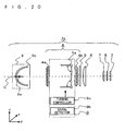
- Fig. 20 is a block diagram of an illumination optical system 1b in a projection display according to a preferred embodiment of the invention.
- the preferred embodiment of the invention is characterized in that the light shielding bodies 9T and 9B in the turning mechanism 9a have a sharp edged tip.
- the other parts of the configuration and the operation are identical to those described in the first example and thus not described here.
- Figs. 21A and 21B are the same drawings as Figs. 15A and 15B ; and Figs. 22A and 22B are similar to Figs. 15A and 15B in the positions of the light shielding bodies 9T and 9B.
- Reference characters 210, 211, 220, and 221 designate the axis passing through the center of the curvature of a lens cell that is the second one in the +y or -y direction from the optical axis C in the second lens array 4b.
- the light shielding bodies 9T and 9B on the optical axis C side of the axis 220 have a sharp edged tip. By so doing, the widths of the tips are reduced by dy.
- the width t of the light shielding bodies 9T and 9B is in general approximately 0.5 mm in consideration of the intensity of the light shielding bodies 9T and 9B with respect to the turning of the turning mechanism 9a.
- Reference characters 212 and 222 designate the tip of the light shielding body 9T.
- reference characters 230 and 230b designate the area with low illumination; and reference characters 231a and 231b designate the y axis passing through the center of the light valve 2.
- Comparison of the areas 230a and 230b shows that unevenness of illumination in the area 230b is considerably improved. Accordingly, as shown in Figs. 22A and 22B , unevenness of illumination can considerably be reduced by sharply edging the tips of the light shielding bodies 9T and 9B on the optical axis C side of the axes passing through the centers of the curvatures of the lens cells that are the second ones in the +y and -y directions from the optical axis C in the second lens array 4b.
- Fig. 24 shows the relative percentage of the amount of light in the y direction on the y axes 231a and 231b shown in Figs. 23A and 23B , respectively.
- reference character 240 designates the relative percentage of the amount of light on the y axis 231a; and reference character 241 designates the relative percentage of the amount of light on the y axis 231b.
- comparison of the values of the relative percentage of the amount of light at 0.50Y, which is the y-direction center of the light valve 2 shows that the relative percentage indicated by 241 is higher than the relative percentage indicated by 240, i.e., unevenness of illumination is considerably reduced.
- Figs. 25A and 25B shows the shape of the tips of the light shielding bodies 9T and 9B.
- Reference characters 250 and 251 designate the axis passing through the center of the curvature of a lens cell that are the second one in the +y or -y direction from the optical axis C in the second lens array 4b. It can be seen from Figs. 25A and 25B that the angles at the tips of the light shielding bodies 9T and 9B should preferably be smaller than ⁇ .
- Fig. 26 is a block diagram of an illumination optical system 1c in a projection display according to a further preferred embodiment of the invention.
- the further preferred embodiment of the invention is characterized in that the light shielding bodies 9T and 9B with small opening areas at their tips can achieve sufficiently high contrast without causing unevenness of illumination on the light valve 2.
- the other parts of the configuration and the operation are identical to those described in the first example and thus not described here.
- the light shielding bodies 9T and 9B should preferably be configured to block light incident at great incident angles on the light valve 2, i.e., to block incident light in the x direction.
- Fig. 28A shows an example of the xy plane of the second lens array 4b and the polarization conversion element 5, in which the right hand part (a) shows a front view and the left hand part (b) shows a side view.
- Fig. 28B shows a detailed representation of Fig. 2 .
- Fig. 28B shows the paths of light incident on the second lens array 4b.
- the dotted line part shows the polarization conversion element 5, and the hatched parts show the ⁇ /2 phase-difference plates 5c.
- polarization conversion is performed with efficiency by concentrating light only in the areas of the ⁇ /2 phase-difference plates 5c.
- light beams 270, 271, 272, 273, 274, and 275 are polarization-converted light beams.
- p-polarized light incident on the polarization conversion element 5 is converted into s-polarized light by the ⁇ /2 phase-difference plates 5c and is thus emitted from the x-direction position of the polarization conversion element 5 that is equivalent to the position of incidence; however, it is emitted to the position that is a distance dx (the distance between 275a and 275b) away from the optical axis C as compared with s-polarized light. Therefore, blocking the incident light on the x-direction side of the optical axis C becomes essential to the improvement in contrast. That is, the light beams 270 and 275 have an influence on the contrast. In other words, the application of light beams to positions that are close to the optical axis C in the x direction is the condition for improvement in contrast.
- Fig. 30 shows the shapes of the light shielding bodies 9T and 9B.
- the light shielding bodies 9T and 9B have two cuts 9g and 9h with different areas at their tips.
- the cuts 9g have a smaller opening area than the cuts 9h.
- the cuts 9g and 9h are formed in the light shielding bodies 9T and 9B to have point symmetry with respect to a point on the optical axis C when the light shielding bodies 9T and 9B are closed.
- Fig. 31 numerically shows the amount of light passing through each cell in the second lens array 4b, which amount is calculated by simulation.
- the shapes of the light shielding bodies 9T and 9B as shown in Fig. 30 can reduce a difference in contrast in the x direction.
- Fig. 31 representatively shows the upper right quadrant of the second lens array 4b since the second lens array 4b shows a symmetry both between upper and lower halves and between right and left halves.
- Fig. 32 shows the simulation result for the case where light emitted from the light source 3a is reflected off the reflecting mirror 3b.
- the reflecting mirror 3b shall be in the shape of an ellipse, and light emitted from the light source system 3 shall be made parallel by a concave lens 310.
- the opening 311 is in such a shape as shown in Fig. 2
- the cell that is in the fourth column V1 and the fifth row H1 (V1H1) of the second lens array 4b shown in Fig. 31 receives only a small amount of light emitted from the light source system 3.
- the light shielding bodies 9T and 9B in the shape of Fig. 30 provide complete light blocking, the cuts 9g irradiate both end portions of the light valve 2 in the x direction, and the cuts 9h irradiate a central portion of the light valve 2. Therefore, a uniform illumination distribution can be obtained by equalizing and superimposing the relative amounts of light applied to the both end portions in the x direction and the central portion of the light valve 2.
- the cuts 9g and 9h are of the same shape, as shown in Fig. 33 , unevenness of illumination occurs due to low illumination in the central portion of the light valve 2. From this, the cuts 9h need to have a larger opening area than the cuts 9g. Referring to Fig. 33 , light emitted from the cuts 9g irradiate an area 32b on the light valve 2, and light emitted from the cuts 9h irradiate an area 32a on the light valve 2.
- Fig. 34 shows the shapes of the light shielding bodies 9T and 9B that are determined in consideration of contrast.
- a cut 9i is formed in the cell (V1H1) to form a right-angled triangular opening, so that a uniform illumination distribution is provided on the light valve 2.
- Fig. 31 shows that only a small amount of light passes through the cell (V1H1).
- V1H1 the contrast of an image projected on the screen is unsatisfactory due to a small amount of light.
- illumination uniformity on the light valve 2 can be achieved with approximately four cells.
- the vertex of each of the cuts 9h with a larger opening area in the x direction is made to be equivalent to the x-direction center of the cell (in the fourth column V1 and the fifth row H1) that is closest to the optical axis C
- the vertex of each of the cuts 9g with a smaller opening area is made to be equivalent to a junction between the cell (in the fourth column V1 and the fifth row H1) that is closest to the optical axis C and the adjacent cell (in the fifth column V2 and the fifth row H1) on the opposite side of the optical axis C.
- Fig. 35 shows the relationship between the turning angle and the relative percentage of the amount of light in the case where the light shielding bodies 9T and 9B are in the shape of Fig. 30 .
- the curve 331 shows the simulation result for the turning mechanism 9a with the shape of Fig. 30 ; and the curve 330 shows the simulation result of Fig. 8 for the turning mechanism 9a with no cut.
- the curve 330 is shifted to overlap with the curve 331.
- the light shielding bodies 9T and 9B in the shape as shown in Fig. 30 allows almost continuous light amount control on the light valve 2 with respect to the turning angle. Accordingly, it can be said that the light shielding bodies 9T and 9B with the tips as shown in Fig. 30 can achieve continuous light amount control without causing unevenness of illumination on the light valve 2, thereby improving the contrast.
- Fig. 36 shows the shapes of the light shielding bodies 9T and 9B.
- the light shielding bodies 9T and 9B have triangular cuts formed at their tips.
- the shape of Fig. 36 allows fine light amount control when the relative percentage of the amount of light is 30% or smaller. Providing the cuts 9g on both sides of the second lens array in the x direction allows fine control of a portion with a low relative percentage of the amount of light.
- the triangular shape as shown in Fig. 36 provides a uniform illumination distribution on the light valve 2 by superimposition of irradiated areas, thereby preventing the occurrence of unevenness of illumination.
- Fig. 37 shows the relationship between the turning angle and the relative percentage of the amount of light in the case where the light shielding bodies 9T and 9B are in the shape of Fig. 36 .
- the curve 351 shows the simulation result for the turning mechanism 9a in the shape of Fig. 36
- the curve 350 shows the simulation result for the turning mechanism in the shape shown in Fig. 38 .
- the curve 350 is shifted to overlap with the curve 351. It can be seen from Fig. 37 that, in the case of the light shielding bodies 9T and 9B of the shape of Fig. 36 , the curve has a gentle inclination around the range between 10% and 30%.
- the reason of such a gentle curve is that, in the case of a small turning angle of the turning mechanism 9a, light blocking in the lens cell in the fourth column V1 and the fifth row H1 shown in Fig. 31 reduces the rate of change of illumination.
- the sensitivity of human eyes to the change in the relative percentage of the amount of light is especially high, so that fine light amount control using the turning mechanism 9a becomes important.
- the shape as shown in Fig. 36 allows fine light amount control when the relative percentage of the amount of light is 30% or smaller.
- the light shielding bodies 9T and 9B with the shape as shown in Fig. 36 allow fine light amount control with a low relative percentage of the amount of light.
Description
- The present invention relates to a projection display with a light-amount control mechanism for adjusting the amount of light applied to a light valve responsive to a video signal.
- A projection display is apt to have difficulty in ensuring high contrast because dark projected images displayed are not sufficiently dark due to leakage of light from various optical elements in an optical system such as a guide optical system and a projection lens and due to stray light (unnecessary light) caused by the optical elements. In particular for image projection on a screen in a dark room, insufficient darkness of dark projected images on display gives to a viewer the impression of low contrast. Especially in projection displays using liquid crystal light valves, although the liquid crystal light valves block transmitted light in response to the polarization property of light, complete blocking of transmitted light is difficult and there is also a limit in counteractive actions taken by video signal processing so that an improvement in contrast is required.
- As a measure to solve this problem, a flat light shielding plate is provided between first and second lens arrays and is turned in response to a video signal to control the amount of light applied to a light valve and thereby to improve the contrast of a projected image on a screen or the like (for example, see
WO2005/026835 ). - In
WO2005/026835 , in the case where the light shielding plate has at its tip a rectangular plane in a direction vertical to the light shielding plate, if the tip of the light shielding plate is in the vicinity of the first lens array and in a position of the center of the curvature of the second lens array in the turning direction of the light shielding plate, the rectangular plane of the light shielding plate is imaged onto a light valve. This undesirably causes linear unevenness of illumination on the light valve in a direction perpendicular to the turning direction and the optical axis direction. Besides, it is difficult to provide satisfactory contrast depending on the shape of the tip of the light shielding plate. -
US 2006/0050249 A1 describes a projector apparatus comprising a light amount control apparatus which has light amount control plates formed by punching a thin metal plate. Said light amount control apparatus is configured to provide opening uniform from a center of the light path to the right and left sides. - An object of the invention is to provide a projection display that achieves continuous light amount control with ease and without causing unevenness of illumination of light applied to a light valve responsive to a video signal, thereby allowing constant image display with satisfactory contrast.
- The object of the present invention is solved by the projection display according to
claim 1. Advantageous developments of the projection display are given in dependent claims. - These and other objects, features, aspects and advantages of the invention will become more apparent from the following detailed description of the invention when taken in conjunction with the accompanying drawings.
-
-
Fig. 1 is a block diagram of an illumination optical system in a projection display according to a first example of the invention; -
Fig. 2 is a block diagram of a polarization conversion element according to the first example of the invention; -
Figs. 3A and 3B show examples of the shapes of a turning mechanism according to the first example of the invention; -
Figs. 4A and 4B show the turning of the turning mechanism according to the first example of the invention; -
Fig. 5 shows the relationship between the turning angle and the relative percentage of the amount of light in the cases where the turning mechanism is in the shapes ofFigs. 3A and 3B according to the first example of the invention; -
Figs. 6A and 6B show the z-direction position of the tip of the turning mechanism when the relative percentage of the amount of light is 20% according to the first example of the invention; -
Fig. 7 shows an illumination distribution of light applied to a light valve when the turning mechanism in the shape ofFig. 3B provides complete light blocking according to the first example of the invention; -
Fig. 8 shows the relationship between the turning angle and the relative percentage of the amount of light in the case where light shielding bodies have no cut according to the first example of the invention; -
Fig. 9 shows light source images in the vicinity of a second lens array according to the first example of the invention; -
Fig. 10 shows an example of the shape of the turning mechanism according to the first example of the invention; -
Fig. 11 shows the relationship between the turning angle and the relative percentage of the amount of light in the case where the turning mechanism is in the shape ofFig. 10 according to the first example of the invention; -
Fig. 12 shows the path of light with respect to the shape of the turning mechanism according to the first example of the invention; -
Figs. 13A and 13B show the paths of light when the turning mechanism has a smaller dimension than the lens arrays according to the first example of the invention; -
Fig. 14 shows the paths of light when reverse ray tracing is performed from the center of the light valve according to the first example of the invention; -
Figs. 15A and 15B show the turning position of the turning mechanism when imaged on the light valve according to the first example of the invention; -
Figs. 16A and 16B show the turning position of the turning mechanism when imaged on the light valve according to the first example of the invention; -
Figs. 17A and 17B show illumination distributions of light applied to the light valve according to the first example of the invention; -
Fig. 18 shows an illumination distribution of light applied to the light valve according to the first example of the invention; -
Fig. 19 shows the relative percentage of the amount of light on y axes ofFigs. 17A, 17B, and 18 according to the first example of the invention; -
Fig. 20 is a block diagram of an illumination optical system in a projection display according to a preferred embodiment of the invention; -
Figs. 21A and 21B show the turning position of the turning mechanism when imaged on the light valve according to the preferred embodiment of the invention; -
Figs. 22A and 22B show the turning position of the turning mechanism when imaged on the light valve according to the preferred embodiment of the invention; -
Figs. 23A and 23B show illumination distributions of light applied to the light valve according to the preferred embodiment of the invention; -
Fig. 24 shows the relative percentage of the amount of light on y axes ofFigs. 23A and 23B according to the preferred embodiment of the invention; -
Figs. 25A and 25B show the shape of the tip of the turning mechanism according to the preferred embodiment of the invention; -
Fig. 26 is a block diagram of an illumination optical system in a projection display according to a further preferred embodiment of the invention; -
Fig. 27 shows the paths of light incident on the light valve according to the further preferred embodiment of the invention; -
Figs. 28A and 28B show the paths of light passing through the second lens array and the polarization conversion element according to the further preferred embodiment of the invention; -
Fig. 29 shows the relationship between the contrast and the angle of incidence of light applied to the light valve according to the further preferred embodiment of the invention; -
Fig. 30 shows an example of the shape of the turning mechanism according to the further preferred embodiment of the invention; -
Fig. 31 shows the amount of light passing through each cell in thesecond lens array 4b according to the further preferred embodiment of the invention; -
Fig. 32 shows the paths of light emitted from alight source 3 according to the further preferred embodiment of the invention; -
Fig. 33 shows an illumination distribution of light applied to the light valve according to the further preferred embodiment of the invention; -
Fig. 34 shows an example of the shape of the turning mechanism according to the further preferred embodiment of the invention; -
Fig. 35 shows the relationship between the turning angle and the relative percentage of the amount of light in the case where the turning mechanism is in the shape ofFig. 30 according to the further preferred embodiment of the invention; -
Fig. 36 shows an example of the shape of the turning mechanism according to the further preferred embodiment of the invention; -
Fig. 37 shows the relationship between the turning angle and the relative percentage of the amount of light in the case where the turning mechanism is in the shape ofFig. 35 according to the further preferred embodiment of the invention; and -
Fig. 38 shows an example of the shape of the turning mechanism according to the further preferred embodiment of the invention. - Preferred embodiments of the invention are described below with reference to the drawings.
-
Fig. 1 is a block diagram of an illuminationoptical system 1 in a projection display according to a first example of the invention. As shown inFig. 1 , the illuminationoptical system 1 includes anintegrator lens 4 between alight source system 3 and alight valve 2, apolarization conversion element 5, a condensinglens 6, afield lens 7, and apolarizing plate 8. The projection display according to the first example of the invention further includes a projection lens (not shown) for projecting light emitted from thelight valve 2 onto a screen. Thelight valve 2 is provided on each of the optical paths of R, G, and B, and the illuminationoptical system 1 shown inFig. 1 is a representative example of any one of those optical paths of R, G, and B. - The
light valve 2 according to the preferred embodiments of the invention is a liquid crystal light valve, but in the case of using lens arrays, it may be other display devices such as a digital micro-mirror device (DMD) and a reflection liquid crystal display device. - The
light source system 3 is configured to apply light to thelight valve 2 and includes a light source 3a and a reflectingmirror 3b that reflects light emitted from the light source 3a to irradiate theintegrator lens 4. The light source 3a is in general a high-pressure mercury lamp, a halogen lamp, or a xenon lamp, but it may be any other light-emitting devices such as a light emitting diode (LED), a laser, and an electrodeless discharge lamp. The reflectingmirror 3b is formed in an elliptical plane or a parabolic plane, but it may be of any shape and any configuration and is not limited to those described as long as light can be concentrated on thepolarization conversion element 5. For example, in order to make incident light on theintegrator lens 4 approximately parallel to an optical axis C, the reflectingmirror 3b should be formed in the shape of a parabola; or if the reflectingmirror 3b is formed in the shape of an ellipse, a concave lens should be provided between thelight source system 3 and the integrator lens 4 (seeFig. 32 ). - The
integrator lens 4 is provided on an optical path between thelight source system 3 and thelight valve 2 and is configured to make uniform the illumination distribution of light applied from thelight source system 3 to thelight valve 2. Theintegrator lens 4 includes afirst lens array 4a and asecond lens array 4b spaced apart from thefirst lens array 4a. Thefirst lens array 4a and thesecond lens array 4b each are an array of a plurality of convex lenses. The convex lenses in thefirst lens array 4a and the convex lenses in thesecond lens array 4b correspond to each other and are located to face each other. - The
polarization conversion element 5 converts light beams incident on thepolarization conversion element 5 into a single type of linearly polarized light and emits the linearly polarized light. It is provided with an appropriate space in the x-axis direction.Fig. 2 is a block diagram of thepolarization conversion element 5 according to the first preferred embodiment of the invention. As shown inFig. 2 , thepolarization conversion element 5 includes a plurality ofpolarization separation films 5a inclined (e.g., 45 degrees) toward the direction of the optical axis C (the z direction); a plurality ofreflection films 5b provided between thepolarization separation films 5a and inclined (e.g., 45 degrees) toward the direction of the optical axis C (the z direction); and λ/2 phase-difference plates 5c provided in a plane of thepolarization conversion element 5 on the side of thelight valve 2 and in positions where light passing through thepolarization separation films 5a are applied. Light incident on thepolarization conversion element 5 is separated into s-polarized light and p-polarized light by thepolarization separation films 5a. The p-polarized light is transmitted through thepolarization separation films 5a, is converted into s-polarized light by the λ/2 phase-difference plates 5c, and then is emitted from thepolarization conversion element 5. On the other hand, the s-polarized light is reflected off thepolarization separation films 5a and off thereflection films 5b and then is emitted from thepolarization conversion element 5. Accordingly, the outgoing beams from thepolarization conversion element 5 are almost all s-polarized light. - The light-amount control system 9 (light-amount control mechanism) is provided on the optical path and includes a
turning mechanism 9a which includes a pair of light shielding bodies that turn like a double door in order to adjust the amount of light applied from thelight source system 3 to thelight valve 2. The light-amount control system 9 includes theturning mechanism 9a provided between thefirst lens array 4a and thesecond lens array 4b; asignal detector 9b detecting a video signal fed to thelight valve 2 and calculating, based on the result of detection, the relative percentage of the amount of light applied to thelight valve 2; and a turningcontroller 9c controlling the turning of theturning mechanism 9a based on the relative percentage of the amount of light calculated by thesignal detector 9b. As shown inFig. 3B , theturning mechanism 9a includeslight shielding bodies light shielding bodies tips cuts 9g that regulate passage of light. Thecuts 9g may be of any shape such as a concave curve, a parabola, a semi-ellipse, and a triangle. - Next, description is given on improvement in contrast. When a video signal represents 100% of the relative percentage of the amount of light, control is performed based on 100% of the relative percentage of the amount of light with no light blocking by the
turning mechanism 9a. For example when a video signal represents 20% of the relative percentage of the amount of light, theturning mechanism 9a blocks the light until the relative percentage of the amount of light becomes 20%, so that approximately a five-fold fine adjustment of the video signal is possible. By lowering the relative percentage of the amount of light by light blocking using theturning mechanism 9a, darker black can be obtained as compared with the case where a video signal represents 0% of the relative percentage of the amount of light in which case no light blocking is provided. In other words, since the transmittance of thelight valve 2 is approximately constant, reducing the amount of light applied to thelight valve 2 using theturning mechanism 9a makes it possible to darken a projected image on a screen, thereby achieving improvement in contrast. -
Fig. 4A shows a 15-degree turning of thelight shielding bodies Fig. 3A , andFig. 4B shows a 15-degree turning of thelight shielding bodies Fig. 3B . Referring to the amounts of travel of the tips of thelight shielding bodies Figs. 4A and 4B , the amount of travel Zb inFig. 4B is smaller than the amount of travel Za inFig. 4A (Za > Zb), from which it can be found that the amount of travel of thelight shielding bodies Fig. 4B . Accordingly, thelight shielding bodies Fig. 4B can provide illumination with 100% of the relative percentage of the amount of light at a smaller turning angle. -
Fig. 5 shows the relationship between the turning angle and the relative percentage of the amount of light in the cases where theturning mechanism 9a is in the shapes ofFigs. 3A and 3B . The angles γT and γB inFig. 3B shall be 20 degrees and theturning mechanism 9a in bothFigs. 3A and 3B turns two degrees at a time. The turning angle of 0 degree refers to the condition that thelight shielding bodies light shielding bodies Fig. 4A and 41b inFig. 4B , respectively. Thecurve 50 shows the simulation result for theturning mechanism 9a in the shape ofFig. 3A , and thecurve 51 shows the simulation result for theturning mechanism 9a in the shape ofFig. 3B . As shown inFig. 5 , thecurve 51 starts to rise earlier than thecurve 50 with a low relative percentage of the amount of light and reaches 100% of the relative percentage of the amount of light at the turning angle of approximately 75 degrees. Because of its narrower operating angle range, the shape ofFig. 3B allows highly responsive control as compared with the shape ofFig. 3A . It can also be seen from thecurves Fig. 14 , in the case of a low relative percentage of the amount of light, unevenness of illumination can be reduced by bending the end portions of thelight shielding bodies Fig. 5 that thelight shielding bodies cuts 9g at the tip as shown inFigs. 3A and 3B allow continuous light amount control. While, in this example of the invention, the angles γT and γB are set to 20 degrees, they may be of any degree, and the same effect can be achieved without satisfying γT = γB. The relationship between the turning angle of theturning mechanism 9a and the relative percentage of the amount of light on thelight valve 2, shown in the example of the invention, is for the case where input is a signal representing 100% of the relative percentage of the amount of light, so that only the property of theturning mechanism 9a is represented. -
Figs. 6A and 6B show the positions of the tips of thelight shielding bodies Fig. 5 . As shown inFig. 6A , the turning angle in the case of the shape ofFig. 3A is approximately 24 degrees, i.e., α1 ≈ 24 , while the turning angle in the case of the shape ofFig. 3B is approximately 34 degrees, i.e., α2 ≈ 34. The angle α3 inFig. 6B is equal to γT and shall be 20 degrees. Let d1 be the length of thelight shielding bodies Fig. 6A ; d2 be the length of thelight shielding bodies Fig. 6B from the turning axis to their bend; and d3 be the length of thelight shielding bodies Fig. 6B from their bends to tips. Based on the conditions described above, the positions of the tips of thelight shielding bodies Fig. 3B in the z direction can be calculated. - From
Figs. 6A and 6B , the amounts of travel Zc and Zd of thelight shielding bodies 

Fig. 4B , d1 can be expressed by the following equation (3).
- Thus, Zc can be expressed by the following equation (4), so that the condition Zc > Zd can be satisfied by equation (5).


- Accordingly, by making the length d2 shorter than the length d3, the shape of
Fig. 3B can reduce unevenness of illumination as compared with the shape ofFig. 3A . Since the distance of travel of the tips of thelight shielding bodies -
Fig. 7 shows the illumination distribution of light applied to thelight valve 2 when the shape ofFig. 3B provides complete light blocking. In the case of complete light blocking, unevenness of illumination does not occur because light incident on thesecond lens array 4b is uniformly superimposed and applied onto the generally whole (area 7a) and around both x-direction end portions (areas 7b) of thelight valve 2. Thearea 7a shows the illumination distribution of light applied from cells to the light valve 2 (area 30 inFig. 3B ) when the opening of the cells in thesecond lens array 4b is approximately full open, and theareas 7b show the illumination distribution of light applied from cells to the light valve 2 (areas 31 inFig. 3B ) when the opening of the cells in thesecond lens array 4b is approximately half opened. -
Fig. 8 shows the relationship between the turning angle and the relative percentage of the amount of light in the case where thelight shielding bodies curve 80 that the rage of change in the relative percentage of the amount of light with respect to the turning angle is not continuous, and that the curve has four flat parts (8a, 8b, 8c, and 8d). -
Fig. 9 shows light source images in the vicinity of thesecond lens array 4b.Fig. 9 shows the images with 256 levels of gray scale. InFig. 9 ,reference characters 91 to 94 designate a dark part between the light source images in the +y direction. The fourflat parts Fig. 8 correspond to the fourdark parts Fig. 9 , which confirms that the dark parts between the light source images are the result of influence of the flat parts inFig. 8 . Thus, in order to provide a continuous change in the amount of light, it is necessary to simultaneously block light in both dark and light parts between the light source images. Since thelight shielding bodies Figs. 3A and 3B allow a continuous change in the amount of light as shown inFig. 5 , simultaneous light blocking in both dark and light parts between the light source images is made possible by forming cuts in thelight shielding bodies -
Fig. 10 shows an example of the shape of thelight shielding bodies
in which thelight shielding bodies single cut 9g to have symmetry with respect to the optical axis C. When such a shape provides complete light blocking, an approximately uniform illumination distribution of light is given on thelight valve 2. -
Fig. 11 shows the relationship between the turning angle and the relative percentage of the amount of light in the case where thelight shielding bodies Fig. 10 . InFig. 10 , the angles γT and γB of thelight shielding bodies curve 110 shows the simulation result for theturning mechanism 9a in the shape ofFig. 10 . Thecurve 80 shows the simulation result shown inFig. 8 for theturning mechanism 9a with no cut, for comparison of the effect between the presence and absence of thecuts 9g. For ease of comparison, thecurve 80 is shifted to overlap with thecurve 110. It can be seen fromFig. 11 that even thelight shielding bodies cut 9g can provide more continuous light amount control than thelight shielding bodies cut 9g in thelight shielding bodies curve 51 inFig. 5 and thecurve 110 inFig. 11 that thelight shielding plates -
Fig. 12 shows the paths of light when thelight shielding bodies first lens array 4a at the time of light blocking, and especially shows the paths of light passing through the lens cell that is farthest in the +y direction in thefirst lens array 4a. Although only thelight shielding body 9T is described here, the same applies to thelight shielding body 9B.Reference character 120a designates the path of light passing through the +y side of the center of the lens cell;reference character 120b designates the path of light passing through the center of the lens cell; andreference character 120c designates the path of light passing through the -y side of the center of the lens cell. As shown inFig. 12 , when thelight shielding body 9T is bent at a small angle or bent in a position that is far from the turning axis, unnecessary light reflected off thelight shielding body 9T passes through thesecond lens array 4b and, after multipath reflection inside a housing (not shown) of the illuminationoptical system 1, it may appear on a screen. From this, thelight shielding bodies second lens array 4b at the time of light blocking are more preferable than thelight shielding bodies Fig. 12 . -
Fig. 13A shows the paths of light when thelight shielding bodies first lens array 4a and thesecond lens array 4b.Fig. 13B shows a comparison of the x- and y-direction dimensions between thelight shielding bodies second lens array 4b, from which it can be seen that thelight shielding bodies second lens array 4b. Although only thelight shielding body 9T is described here, the same applies to thelight shielding body 9B. Reference character 130a designates the path of light passing through the center of the lens cell that is the fifth one in the +y direction from the optical axis C in thefirst lens array 4a; andreference character 130b designates the path of light passing through the +x side of the center of the lens cell that is the second one in the +y direction and the third one in the +x direction from the optical axis C in thefirst lens array 4a. It can be seen fromFig. 13A that light passing through those cells which are on the +y side of the turning axes of thelight shielding bodies first lens array 4a passes through the +y side without entering thelight shielding bodies first lens array 4a using thelight shielding bodies light shielding bodies first lens array 4a and thesecond lens array 4b. In the case where thesecond lens array 4b is larger in dimension than thefirst lens array 4a, although it is preferable that thelight shielding bodies second lens array 4b, it is also possible to block unnecessary light passing through thesecond lens array 4b by providing a light shielding plate between thesecond lens array 4b and thepolarization conversion element 5. From this, it can be said that thelight shielding bodies first lens array 4a and thesecond lens array 4b. -
Fig. 14 shows the paths of light calculated by reverse ray tracing from the center of thelight valve 2.Reference character 140 designates the paths of light; andreference character 141 designates the area where the paths of light indicated by 140 are concentrated. Since it can be seen fromFig. 14 that an image in the vicinity of thefirst lens array 4a is formed on thelight valve 2, thelight valve 2 and the neighborhood of the light incident surface of thefirst lens array 4a are in conjugation. Thus, when the tips of thelight shielding bodies area 141, the tips of thelight shielding bodies light valve 2, which undesirably causes linear unevenness of illumination in the x direction in the vicinity of the center on thelight valve 2. , Therefore, it is preferable that the tips of thelight shielding bodies second lens array 4b, i.e., the turning axes are in the vicinity of thesecond lens array 4b. - Focusing on the tips of the
light shielding bodies light shielding bodies light shielding bodies Fig. 15B and dy2 inFig. 16B ), they can reduce unevenness of illumination on thelight valve 2. Therefore, it can be said that unevenness of illumination on thelight valve 2 can be reduced by bending thelight shielding bodies -
Figs. 15A and 15B andFigs. 16A and 16B show the turning positions of thelight shielding bodies Figs. 3A and 3B when the tips of thelight shielding bodies light valve 2. The condition that an image is formed on thelight valve 2 is that the tips of thelight shielding bodies first lens array 4a and in positions that are equivalent to the centers of the curvatures of the lens cells that are the second ones in the +y and -y directions from the optical axis C in thesecond lens array 4b.Reference characters second lens array 4b; andreference characters light shielding body 9T. - Now we describe the reason why the tips of the
light shielding bodies second lens array 4b. First of all, in positions that are equivalent to the centers of the curvatures of the lens cells that are the first ones in the +y and -y directions from the optical axis C in thesecond lens array 4b, it is difficult to check unevenness of illumination on thelight valve 2 due to low illumination. In positions that are equivalent to the centers of the curvatures of the lens cells that are the third ones in the +y and -y directions from the optical axis in thesecond lens array 4b, light with illumination uniformity is superimposed on thelight valve 2 from the lens cells that are the first ones in the +y and -y directions from the optical axis C and from the lens cells that are the second ones in the +y and -y directions from the optical axis C, which relatively reduces unevenness of illumination on thelight valve 2 and thus makes it difficult to check unevenness of illumination caused by the lens cells that are the third ones in the +y and -y directions from the optical axis C. Accordingly, as a condition that allows the easy checking of imaging of the tips of thelight shielding bodies light valve 2, the tips of thelight shielding bodies second lens array 4b. -
Figs. 17A shows the simulation result of the illumination distribution on thelight valve 2 when thelight shielding bodies cut 9g as shown inFig. 3A and are in the condition ofFigs. 15A and 15B ; andFig. 17B shows the simulation result of the illumination distribution on thelight valve 2 when thelight shielding bodies cut 9g as shown inFig. 3B and are in the condition ofFigs. 16A and 16B . InFigs. 17A and 17B ,reference characters reference characters light valve 2. The comparison of theareas area 170b has higher illumination uniformity than thearea 170a. This is because there is the inequality relation dy1 > dy2 between the width dy1 ofFig. 15B and the width dy2 ofFig. 16B . Accordingly, unevenness of illumination on thelight valve 2 can be reduced by bending thelight shielding bodies light shielding bodies -
Fig. 18 shows the simulation result of the illumination distribution on thelight valve 2 when thelight shielding bodies Fig. 3B and in the condition ofFigs. 16A and 16B . As shown inFig. 18 , there is little area with low illumination in the x direction from the center of thelight valve 2.Reference character 180 designates the area with low illumination in y direction extending from the center of thelight valve 2; andreference character 181 designates the y axis passing through the center of thelight valve 2. Although there is only some slight unevenness of illumination in thearea 180 because of thecuts 9g in thelight shielding bodies second lens array 4b, this is not a problem because the whole illumination distribution of thelight valve 2 is approximately uniform. Accordingly, superimposition of the tips imaged on thelight valve 2 can be reduced by bending thelight shielding bodies light shielding bodies -
Fig. 19 shows the relative percentage of the amount of light in the y direction on they axes Figs. 17A and 17B and Fig. 18 , respectively. The horizontal axis corresponds to the vertical axis on thelight valve 2 shown inFig. 18 . InFig, 19 ,reference character 190 designates the relative percentage of the amount of light on the y axis 171a;reference character 191 designates the relative percentage of the amount of light on they axis 171b; andreference character 192 designates the relative percentage of the amount of light on they axis 181. Referring toFig. 19 , comparison of the values of the relative percentage of the amount of light at 0.50Y, which is the y-direction center of thelight valve 2, yields theinequality 190<191<192 and shows that unevenness of illumination decreases in the order of 190, 191, and 192. This indicates that unevenness of illumination can be reduced by forming thelight shielding bodies - While this example has described the case where γT = α2 = α3 in
Fig. 6B when thelight shielding bodies position 41b shown inFig. 4B , the width dy2 inFig. 16B can further be reduced in the case where α3 > α2 = γT, in which case unevenness of illumination can further be reduced than in the case of the shape ofFig. 4B . Further, while thelight shielding bodies Fig. 16B can further be reduced. By so doing, unevenness of illumination can further be reduced. While thelight shielding bodies Fig. 3B are bent in the vicinity of the lens cell that is the second one in the y direction from the optical axis C as a center in thesecond lens array 4b, they may be bent in any position. - From the above description, it is clear that continuous light amount control without causing unevenness of illumination on the
light valve 2 can be achieved by forming thelight shielding bodies turning mechanism 9a with a V-shaped bend in a direction to reduce the amount of light (to block the light) and with at least one cut at their tips. -
Fig. 20 is a block diagram of an illuminationoptical system 1b in a projection display according to a preferred embodiment of the invention. The preferred embodiment of the invention is characterized in that thelight shielding bodies turning mechanism 9a have a sharp edged tip. The other parts of the configuration and the operation are identical to those described in the first example and thus not described here. -
Figs. 21A and 21B are the same drawings asFigs. 15A and 15B ; andFigs. 22A and 22B are similar toFigs. 15A and 15B in the positions of thelight shielding bodies Reference characters second lens array 4b. As shown inFigs. 22A and 22B , thelight shielding bodies axis 220 have a sharp edged tip. By so doing, the widths of the tips are reduced by dy. The width t of thelight shielding bodies light shielding bodies turning mechanism 9a.Reference characters light shielding body 9T. -
Fig. 23A shows the simulation result of the illumination distribution on thelight valve 2 when thelight shielding bodies cut 9g as shown inFig. 3A and are in the condition ofFigs. 21A and 21B ; andFig. 23B shows the simulation result of the illumination distribution on thelight valve 2 when thelight shielding bodies cut 9g as shown inFig. 3A and are in the condition ofFigs. 22A and 22B . It is assumed that t = 0.55 mm. InFigs. 23A and 23B ,reference characters reference characters light valve 2. Comparison of theareas 230a and 230b shows that unevenness of illumination in thearea 230b is considerably improved. Accordingly, as shown inFigs. 22A and 22B , unevenness of illumination can considerably be reduced by sharply edging the tips of thelight shielding bodies second lens array 4b. -
Fig. 24 shows the relative percentage of the amount of light in the y direction on they axes Figs. 23A and 23B , respectively. InFig. 24 ,reference character 240 designates the relative percentage of the amount of light on the y axis 231a; andreference character 241 designates the relative percentage of the amount of light on they axis 231b. Referring toFig. 24 , comparison of the values of the relative percentage of the amount of light at 0.50Y, which is the y-direction center of thelight valve 2, shows that the relative percentage indicated by 241 is higher than the relative percentage indicated by 240, i.e., unevenness of illumination is considerably reduced. This indicates that unevenness of illumination can considerably be reduced by sharply edging the tips of thelight shielding bodies second lens array 4b. -
Figs. 25A and 25B shows the shape of the tips of thelight shielding bodies Reference characters second lens array 4b. It can be seen fromFigs. 25A and 25B that the angles at the tips of thelight shielding bodies - From the above description, it is clear that continuous light amount control without causing unevenness of illumination on the
light valve 2 can be achieved by forming at least one cut at the tips of thelight shielding bodies light shielding bodies -
Fig. 26 is a block diagram of an illumination optical system 1c in a projection display according to a further preferred embodiment of the invention. The further preferred embodiment of the invention is characterized in that thelight shielding bodies light valve 2. The other parts of the configuration and the operation are identical to those described in the first example and thus not described here. -
Light 270 emitted from thesecond lens array 4b is incident on thelight valve 2 at a great incident angle. At this time, since the contrast decreases with increasing incident angle of light on thelight valve 2 due to the property of light valves (seeFig. 29 ), thelight shielding bodies light valve 2, i.e., to block incident light in the x direction. -
Fig. 28A shows an example of the xy plane of thesecond lens array 4b and thepolarization conversion element 5, in which the right hand part (a) shows a front view and the left hand part (b) shows a side view.Fig. 28B shows a detailed representation ofFig. 2 . Also,Fig. 28B shows the paths of light incident on thesecond lens array 4b. The dotted line part shows thepolarization conversion element 5, and the hatched parts show the λ/2 phase-difference plates 5c. In general, polarization conversion is performed with efficiency by concentrating light only in the areas of the λ/2 phase-difference plates 5c. Thus,light beams Fig. 28B , out of linearly p- and s-polarized incident light, p-polarized light incident on thepolarization conversion element 5 is converted into s-polarized light by the λ/2 phase-difference plates 5c and is thus emitted from the x-direction position of thepolarization conversion element 5 that is equivalent to the position of incidence; however, it is emitted to the position that is a distance dx (the distance between 275a and 275b) away from the optical axis C as compared with s-polarized light. Therefore, blocking the incident light on the x-direction side of the optical axis C becomes essential to the improvement in contrast. That is, the light beams 270 and 275 have an influence on the contrast. In other words, the application of light beams to positions that are close to the optical axis C in the x direction is the condition for improvement in contrast. -
Fig. 30 shows the shapes of thelight shielding bodies light shielding bodies cuts cuts 9g have a smaller opening area than thecuts 9h. Thecuts light shielding bodies light shielding bodies -
Fig. 31 numerically shows the amount of light passing through each cell in thesecond lens array 4b, which amount is calculated by simulation. The shapes of thelight shielding bodies Fig. 30 can reduce a difference in contrast in the x direction.Fig. 31 representatively shows the upper right quadrant of thesecond lens array 4b since thesecond lens array 4b shows a symmetry both between upper and lower halves and between right and left halves. -
Fig. 32 shows the simulation result for the case where light emitted from the light source 3a is reflected off the reflectingmirror 3b. The reflectingmirror 3b shall be in the shape of an ellipse, and light emitted from thelight source system 3 shall be made parallel by aconcave lens 310. In general, there is a valve of the light source in the vicinity of the optical axis C, andreference character 311 designates an opening of such a valve. - Since the
opening 311 is in such a shape as shown inFig. 2 , the cell that is in the fourth column V1 and the fifth row H1 (V1H1) of thesecond lens array 4b shown inFig. 31 receives only a small amount of light emitted from thelight source system 3. When thelight shielding bodies Fig. 30 provide complete light blocking, thecuts 9g irradiate both end portions of thelight valve 2 in the x direction, and thecuts 9h irradiate a central portion of thelight valve 2. Therefore, a uniform illumination distribution can be obtained by equalizing and superimposing the relative amounts of light applied to the both end portions in the x direction and the central portion of thelight valve 2. For example when thecuts Fig. 33 , unevenness of illumination occurs due to low illumination in the central portion of thelight valve 2. From this, thecuts 9h need to have a larger opening area than thecuts 9g. Referring toFig. 33 , light emitted from thecuts 9g irradiate anarea 32b on thelight valve 2, and light emitted from thecuts 9h irradiate an area 32a on thelight valve 2. -
Fig. 34 shows the shapes of thelight shielding bodies light valve 2. However,Fig. 31 shows that only a small amount of light passes through the cell (V1H1). Thus in the case where a 100 percent video signal is displayed on the screen, the contrast of an image projected on the screen is unsatisfactory due to a small amount of light. - From the above, generally, in order to prevent the occurrence of unevenness of illumination on the
light valve 2, approximately eight cells are necessary as an opening. However, by consideration of the shape and the relative percentage of the amount of light incident on the opening, illumination uniformity on thelight valve 2 can be achieved with approximately four cells. Specifically, the vertex of each of thecuts 9h with a larger opening area in the x direction is made to be equivalent to the x-direction center of the cell (in the fourth column V1 and the fifth row H1) that is closest to the optical axis C, and the vertex of each of thecuts 9g with a smaller opening area is made to be equivalent to a junction between the cell (in the fourth column V1 and the fifth row H1) that is closest to the optical axis C and the adjacent cell (in the fifth column V2 and the fifth row H1) on the opposite side of the optical axis C. By so doing, improvement in contrast can be achieved with approximately four cells, without causing unevenness of illumination on thelight valve 2. -
Fig. 35 shows the relationship between the turning angle and the relative percentage of the amount of light in the case where thelight shielding bodies Fig. 30 . Thecurve 331 shows the simulation result for theturning mechanism 9a with the shape ofFig. 30 ; and thecurve 330 shows the simulation result ofFig. 8 for theturning mechanism 9a with no cut. For ease of comparison, thecurve 330 is shifted to overlap with thecurve 331. It can be seen fromFig. 35 that thelight shielding bodies Fig. 30 allows almost continuous light amount control on thelight valve 2 with respect to the turning angle. Accordingly, it can be said that thelight shielding bodies Fig. 30 can achieve continuous light amount control without causing unevenness of illumination on thelight valve 2, thereby improving the contrast. - While this preferred embodiment illustrates an example of the cuts in the shape of an ellipse, the same effect can be achieved with cuts in the shape of a triangle as long as the same consideration as described in this preferred embodiment is given on the opening area and the positions of the vertices.
-
Fig. 36 shows the shapes of thelight shielding bodies light shielding bodies Fig. 36 allows fine light amount control when the relative percentage of the amount of light is 30% or smaller. Providing thecuts 9g on both sides of the second lens array in the x direction allows fine control of a portion with a low relative percentage of the amount of light. Although only a small number of cells in thesecond lens array 4b are used for complete light blocking, the triangular shape as shown inFig. 36 provides a uniform illumination distribution on thelight valve 2 by superimposition of irradiated areas, thereby preventing the occurrence of unevenness of illumination. -
Fig. 37 shows the relationship between the turning angle and the relative percentage of the amount of light in the case where thelight shielding bodies Fig. 36 . Thecurve 351 shows the simulation result for theturning mechanism 9a in the shape ofFig. 36 , and thecurve 350 shows the simulation result for the turning mechanism in the shape shown inFig. 38 . For ease of comparison, thecurve 350 is shifted to overlap with thecurve 351. It can be seen fromFig. 37 that, in the case of thelight shielding bodies Fig. 36 , the curve has a gentle inclination around the range between 10% and 30%. The reason of such a gentle curve is that, in the case of a small turning angle of theturning mechanism 9a, light blocking in the lens cell in the fourth column V1 and the fifth row H1 shown inFig. 31 reduces the rate of change of illumination. In the range with a low relative percentage of the amount of light, namely between 10% and 30%, the sensitivity of human eyes to the change in the relative percentage of the amount of light is especially high, so that fine light amount control using theturning mechanism 9a becomes important. The shape as shown inFig. 36 allows fine light amount control when the relative percentage of the amount of light is 30% or smaller. - From the above description, the
light shielding bodies Fig. 36 allow fine light amount control with a low relative percentage of the amount of light.
Claims (12)
- A projection display comprising:a light valve (2);a light source (3a) generating light applied to said light valve (2);an integrator lens (4) provided on an optical path with an optical axis between said light source (3a) and said light valve (2) and making uniform an illumination distribution of light applied from said light source (3a) to said light valve (2); anda light-amount control mechanism (9) provided on said optical path and including a pair of light shielding bodies (9B, 9T) arranged on opposite sides of the optical axis (C), each light shielding body (98, 9T) being arranged in a turnable manner around a turning axis so as to adjust the amount of light passing from said light source (3a) to said light valve (2), the turning axes being arranged parallel to each other and orthogonal to the optical axis (C), wherein each of said light shielding bodies is shaped as a plate, and whereinthe thickness of said light shielding bodies (98, 9T) is reduced at their tips so that the light-shielding bodies (9B, 9T) have sharply edged tips on their optical axis side.
- The projection display according to claim 1,
wherein said light shielding bodies (9B, 9T) have a cut at their tips. - The projection display according to claim 1,
wherein
said integrator lens (4) includes a first lens array (4a) provided on the side of said light source (3a), and a second lens array (4b) provided on the side of said light valve (2), and
said light shielding bodies (9B, 9T) are provided between said first lens array (4a) and said second lens array (4b), and turn in a direction to open toward and close away from said first lens array (4a). - The projection display according to claim 3,
wherein turning axes of said light shielding bodies (9B, 9T) are between said first lens array (4a) and said second lens array (4b) and the turning axis of the light shielding bodies are closer to the second lens array than to the first lens array. - The projection display according to claim 1,
wherein said pair of light shieldihg bodies (9B, 9T) have a larger dimension in a direction of the radius of turning than said integrator lens (4). - The projection display according to claim 2,
wherein said cut is formed in the shape of a concave curve. - The projection display according to claim 2,
wherein said cut is formed in the shape of a parabola. - The projection display according to claim 2,
wherein said cut is formed in the shape of a semi-ellipse. - The projection display according to claim 2,
wherein said cut is formed in the shape of a triangle. - The projection display according to claim 1,
wherein said light shielding bodies (98, 9T) have a plurality of cuts at their tips. - The projection display according to claim 3,
wherein said light shielding bodies (98, 9T) have respectively two cuts that have different areas and are formed in said light shielding bodies (9B, 9T) to have point symmetry with respect to a point on an optical axis when said light shielding bodies (9B, 9T) are closed. - The projection display according to claim 11,
wherein in an xyz coordinate system where the z axis is a direction of said optical axis, the x axis is a lateral direction orthogonal to said z axis, and the y axis is a vertical direction orthogonal to said z axis and said x axis, said two cuts with different areas are such that when the light-shielding bodies (9B, 9T) are closed:one of said two cuts of one of said light shielding bodies which has a larger opening area has a vertex that is in y-axis direction beside the center of a lens cell of said second lens array, said lens all being closest to said optical axis, andone of said two cuts of the other of said light shielding bodies which has a smaller opening area has a vertex that is in y-axis direction beside a junction between said lens cell and another lens cell that is on the x axis and that is adjacent to said lens cell on the side of said lens cell opposite said optical axis.
Applications Claiming Priority (3)
| Application Number | Priority Date | Filing Date | Title |
|---|---|---|---|
| JP2007149366 | 2007-06-05 | ||
| JP2008032978A JP5100430B2 (en) | 2007-06-05 | 2008-02-14 | Projection display |
| EP08009933A EP2001226B1 (en) | 2007-06-05 | 2008-05-30 | Projection display |
Related Parent Applications (3)
| Application Number | Title | Priority Date | Filing Date |
|---|---|---|---|
| EP08009933A Division EP2001226B1 (en) | 2007-06-05 | 2008-05-30 | Projection display |
| EP08009933 Previously-Filed-Application | 2008-05-30 | ||
| EP08009933.6 Division | 2008-05-30 |
Publications (3)
| Publication Number | Publication Date |
|---|---|
| EP2073537A2 EP2073537A2 (en) | 2009-06-24 |
| EP2073537A3 EP2073537A3 (en) | 2011-07-13 |
| EP2073537B1 true EP2073537B1 (en) | 2012-08-01 |
Family
ID=39666226
Family Applications (3)
| Application Number | Title | Priority Date | Filing Date |
|---|---|---|---|
| EP09003309A Active EP2071834B1 (en) | 2007-06-05 | 2008-05-30 | Projection display |
| EP09003308A Active EP2073537B1 (en) | 2007-06-05 | 2008-05-30 | Projection display |
| EP08009933A Active EP2001226B1 (en) | 2007-06-05 | 2008-05-30 | Projection display |
Family Applications Before (1)
| Application Number | Title | Priority Date | Filing Date |
|---|---|---|---|
| EP09003309A Active EP2071834B1 (en) | 2007-06-05 | 2008-05-30 | Projection display |
Family Applications After (1)
| Application Number | Title | Priority Date | Filing Date |
|---|---|---|---|
| EP08009933A Active EP2001226B1 (en) | 2007-06-05 | 2008-05-30 | Projection display |
Country Status (3)
| Country | Link |
|---|---|
| US (2) | US8052285B2 (en) |
| EP (3) | EP2071834B1 (en) |
| CA (1) | CA2631144C (en) |
Families Citing this family (8)
| Publication number | Priority date | Publication date | Assignee | Title |
|---|---|---|---|---|
| US6947025B2 (en) * | 2001-10-09 | 2005-09-20 | Seiko Epson Corporation | Lighting apparatus and projection type display, and driving method therefore |
| JP4661954B2 (en) * | 2008-03-10 | 2011-03-30 | セイコーエプソン株式会社 | Light control device, lighting device, and projector |
| JP5334494B2 (en) * | 2008-08-20 | 2013-11-06 | 三菱電機株式会社 | Projection display |
| JP5332652B2 (en) * | 2009-01-27 | 2013-11-06 | セイコーエプソン株式会社 | projector |
| JP5267250B2 (en) * | 2009-03-18 | 2013-08-21 | セイコーエプソン株式会社 | Light control device and lighting device for projector using the light control device |
| JP5509845B2 (en) * | 2009-10-27 | 2014-06-04 | セイコーエプソン株式会社 | projector |
| US9703184B2 (en) | 2011-08-12 | 2017-07-11 | Seiko Epson Corporation | Dimmer and projector |
| EP3245095B1 (en) | 2015-01-16 | 2018-10-31 | Volvo Truck Corporation | Method and device for controlling an electric or a hybrid electric vehicle |
Family Cites Families (31)
| Publication number | Priority date | Publication date | Assignee | Title |
|---|---|---|---|---|
| US2896525A (en) | 1954-04-05 | 1959-07-28 | James D Smith | Focal plane shutter |
| US5924783A (en) * | 1997-07-24 | 1999-07-20 | Raychem Corporation | System for controlling contrast in projection displays |
| JP4005292B2 (en) * | 2000-02-18 | 2007-11-07 | フジノン株式会社 | Illumination optical system and projection display device using the same |
| US6947025B2 (en) * | 2001-10-09 | 2005-09-20 | Seiko Epson Corporation | Lighting apparatus and projection type display, and driving method therefore |
| JP4075509B2 (en) | 2002-08-06 | 2008-04-16 | セイコーエプソン株式会社 | Illumination optical device and projector provided with illumination optical device |
| JP4158611B2 (en) * | 2002-09-06 | 2008-10-01 | 株式会社日立製作所 | Projection-type image display device |
| JP4254442B2 (en) * | 2002-10-11 | 2009-04-15 | セイコーエプソン株式会社 | Lighting device and projector |
| US7029127B2 (en) | 2003-03-06 | 2006-04-18 | Seiko Epson Corporation | Projector |
| JP4158618B2 (en) | 2003-05-15 | 2008-10-01 | セイコーエプソン株式会社 | Projection type display device and driving method of projection type display device |
| JP4165312B2 (en) | 2003-06-24 | 2008-10-15 | セイコーエプソン株式会社 | Illumination device, projection display device |
| JP2005017501A (en) | 2003-06-24 | 2005-01-20 | Seiko Epson Corp | Lighting system, projection type display and the method of driving the same |
| JP4166170B2 (en) * | 2003-07-01 | 2008-10-15 | 三洋電機株式会社 | Projection display device |
| US6769777B1 (en) * | 2003-08-20 | 2004-08-03 | Honeywell International Inc. | Multi-aperture optical dimming system |
| CN100495197C (en) | 2003-09-10 | 2009-06-03 | 松下电器产业株式会社 | Projection display |
| US7344255B2 (en) * | 2004-04-01 | 2008-03-18 | Nisca Corporation | Light amount adjusting apparatus and projector using the same |
| US7182470B2 (en) | 2004-09-09 | 2007-02-27 | Nisca Corporation | Light amount control apparatus and projector apparatus using the same |
| JP2006078784A (en) | 2004-09-09 | 2006-03-23 | Nisca Corp | Device for adjusting light quantity, and projector device using the same |
| JP4789488B2 (en) * | 2005-03-11 | 2011-10-12 | キヤノン株式会社 | Optical system and image projection apparatus |
| JP4823574B2 (en) | 2005-06-08 | 2011-11-24 | 日本電産コパル株式会社 | Projector aperture device |
| KR100653248B1 (en) * | 2005-06-23 | 2006-12-01 | 삼성전기주식회사 | Light quaint adjusting apparatus |
| JP5002923B2 (en) * | 2005-08-09 | 2012-08-15 | 株式会社日立製作所 | Projection-type image display device |
| JP4904741B2 (en) | 2005-08-09 | 2012-03-28 | 株式会社日立製作所 | Projection-type image display device and shading method |
| JP4357469B2 (en) * | 2005-09-09 | 2009-11-04 | 三洋電機株式会社 | Projector device |
| US20070064293A1 (en) * | 2005-09-16 | 2007-03-22 | Texas Instruments Incorporated | Method of adjusting the resonant frequency of an assembled torsional hinged device |
| JP2007086302A (en) | 2005-09-21 | 2007-04-05 | Konica Minolta Opto Inc | Image projecting device having variable diaphragm |
| TWI307444B (en) * | 2006-07-20 | 2009-03-11 | Coretronic Corp | Imaging system and projection apparatus |
| JP4197527B2 (en) * | 2006-08-18 | 2008-12-17 | 三菱電機株式会社 | Projection display |
| JP4271242B2 (en) * | 2007-03-09 | 2009-06-03 | 三菱電機株式会社 | Aperture driving device and projection-type image display device |
| JP4661954B2 (en) * | 2008-03-10 | 2011-03-30 | セイコーエプソン株式会社 | Light control device, lighting device, and projector |
| JP2010008767A (en) * | 2008-06-27 | 2010-01-14 | Hitachi Ltd | Optical unit and projection type video display |
| JP5267250B2 (en) * | 2009-03-18 | 2013-08-21 | セイコーエプソン株式会社 | Light control device and lighting device for projector using the light control device |
-
2008
- 2008-05-12 CA CA2631144A patent/CA2631144C/en active Active
- 2008-05-16 US US12/153,352 patent/US8052285B2/en active Active
- 2008-05-30 EP EP09003309A patent/EP2071834B1/en active Active
- 2008-05-30 EP EP09003308A patent/EP2073537B1/en active Active
- 2008-05-30 EP EP08009933A patent/EP2001226B1/en active Active
-
2011
- 2011-09-22 US US13/240,046 patent/US8684542B2/en active Active
Also Published As
| Publication number | Publication date |
|---|---|
| EP2073537A2 (en) | 2009-06-24 |
| CA2631144A1 (en) | 2008-12-05 |
| US8684542B2 (en) | 2014-04-01 |
| EP2071834A2 (en) | 2009-06-17 |
| EP2001226A1 (en) | 2008-12-10 |
| EP2001226B1 (en) | 2012-08-01 |
| US20120008107A1 (en) | 2012-01-12 |
| EP2071834A3 (en) | 2011-07-13 |
| EP2073537A3 (en) | 2011-07-13 |
| US20080304022A1 (en) | 2008-12-11 |
| EP2071834B1 (en) | 2012-08-15 |
| CA2631144C (en) | 2011-03-15 |
| US8052285B2 (en) | 2011-11-08 |
Similar Documents
| Publication | Publication Date | Title |
|---|---|---|
| CA2716963C (en) | Projection display | |
| EP2073537B1 (en) | Projection display | |
| US6808271B1 (en) | Projection type display apparatus | |
| EP3425437B1 (en) | Patterned light irradiation apparatus and method | |
| US9690179B2 (en) | Illumination unit and image display device incorporating same | |
| US10133185B2 (en) | Illumination optical apparatus and device manufacturing method | |
| US9638992B2 (en) | Illumination optical system and image projection apparatus | |
| EP2157788B1 (en) | Projection display apparatus | |
| US20120033421A1 (en) | Light source device and projection type display apparatus | |
| US20100321659A1 (en) | Illumination Arrangement | |
| JP2006098451A (en) | Projector and polarizing member used for the projector or the like | |
| JP2019049722A (en) | Method for manufacturing projection optical system and method for manufacturing image display device | |
| KR20070019426A (en) | Laser projection display system provided with a pair of optical elements for decreasing speckle | |
| JP2009145452A (en) | Light irradiating device | |
| CN101957544A (en) | Diaphragm device and projection device used therefor | |
| JP2017083500A (en) | Reflection-type image display device | |
| JPH03146919A (en) | Projector |
Legal Events
| Date | Code | Title | Description |
|---|---|---|---|
| PUAI | Public reference made under article 153(3) epc to a published international application that has entered the european phase |
Free format text: ORIGINAL CODE: 0009012 |
|
| AC | Divisional application: reference to earlier application |
Ref document number: 2001226 Country of ref document: EP Kind code of ref document: P |
|
| AK | Designated contracting states |
Kind code of ref document: A2 Designated state(s): AT BE BG CH CY CZ DE DK EE ES FI FR GB GR HR HU IE IS IT LI LT LU LV MC MT NL NO PL PT RO SE SI SK TR |
|
| AX | Request for extension of the european patent |
Extension state: AL BA MK RS |
|
| PUAL | Search report despatched |
Free format text: ORIGINAL CODE: 0009013 |
|
| AK | Designated contracting states |
Kind code of ref document: A3 Designated state(s): AT BE BG CH CY CZ DE DK EE ES FI FR GB GR HR HU IE IS IT LI LT LU LV MC MT NL NO PL PT RO SE SI SK TR |
|
| AX | Request for extension of the european patent |
Extension state: AL BA MK RS |
|
| 17P | Request for examination filed |
Effective date: 20110907 |
|
| GRAP | Despatch of communication of intention to grant a patent |
Free format text: ORIGINAL CODE: EPIDOSNIGR1 |
|
| AKX | Designation fees paid |
Designated state(s): DE ES FR GB IT SE |
|
| GRAS | Grant fee paid |
Free format text: ORIGINAL CODE: EPIDOSNIGR3 |
|
| GRAA | (expected) grant |
Free format text: ORIGINAL CODE: 0009210 |
|
| AC | Divisional application: reference to earlier application |
Ref document number: 2001226 Country of ref document: EP Kind code of ref document: P |
|
| AK | Designated contracting states |
Kind code of ref document: B1 Designated state(s): DE ES FR GB IT SE |
|
| REG | Reference to a national code |
Ref country code: GB Ref legal event code: FG4D |
|
| REG | Reference to a national code |
Ref country code: SE Ref legal event code: TRGR |
|
| REG | Reference to a national code |
Ref country code: DE Ref legal event code: R096 Ref document number: 602008017726 Country of ref document: DE Effective date: 20120927 |
|
| REG | Reference to a national code |
Ref country code: ES Ref legal event code: FG2A Ref document number: 2391493 Country of ref document: ES Kind code of ref document: T3 Effective date: 20121127 |
|
| PG25 | Lapsed in a contracting state [announced via postgrant information from national office to epo] |
Ref country code: IT Free format text: LAPSE BECAUSE OF FAILURE TO SUBMIT A TRANSLATION OF THE DESCRIPTION OR TO PAY THE FEE WITHIN THE PRESCRIBED TIME-LIMIT Effective date: 20120801 |
|
| PLBE | No opposition filed within time limit |
Free format text: ORIGINAL CODE: 0009261 |
|
| STAA | Information on the status of an ep patent application or granted ep patent |
Free format text: STATUS: NO OPPOSITION FILED WITHIN TIME LIMIT |
|
| 26N | No opposition filed |
Effective date: 20130503 |
|
| REG | Reference to a national code |
Ref country code: DE Ref legal event code: R097 Ref document number: 602008017726 Country of ref document: DE Effective date: 20130503 |
|
| GBPC | Gb: european patent ceased through non-payment of renewal fee |
Effective date: 20130530 |
|
| PG25 | Lapsed in a contracting state [announced via postgrant information from national office to epo] |
Ref country code: GB Free format text: LAPSE BECAUSE OF NON-PAYMENT OF DUE FEES Effective date: 20130530 |
|
| REG | Reference to a national code |
Ref country code: DE Ref legal event code: R082 Ref document number: 602008017726 Country of ref document: DE Representative=s name: PFENNING, MEINIG & PARTNER MBB PATENTANWAELTE, DE Ref country code: DE Ref legal event code: R081 Ref document number: 602008017726 Country of ref document: DE Owner name: SEIKO EPSON CORPORATION, SHINJUKU-KU, JP Free format text: FORMER OWNER: MITSUBISHI ELECTRIC CORPORATION, TOKYO, JP |
|
| REG | Reference to a national code |
Ref country code: FR Ref legal event code: PLFP Year of fee payment: 9 |
|
| REG | Reference to a national code |
Ref country code: ES Ref legal event code: PC2A Owner name: SEIKO EPSON CORPORATION Effective date: 20160509 |
|
| REG | Reference to a national code |
Ref country code: FR Ref legal event code: TP Owner name: SEIKO EPSON CORPORATION, JP Effective date: 20160916 |
|
| REG | Reference to a national code |
Ref country code: FR Ref legal event code: PLFP Year of fee payment: 10 |
|
| REG | Reference to a national code |
Ref country code: FR Ref legal event code: PLFP Year of fee payment: 11 |
|
| REG | Reference to a national code |
Ref country code: FR Ref legal event code: PLFP Year of fee payment: 16 |
|
| PGFP | Annual fee paid to national office [announced via postgrant information from national office to epo] |
Ref country code: FR Payment date: 20230411 Year of fee payment: 16 Ref country code: ES Payment date: 20230601 Year of fee payment: 16 Ref country code: DE Payment date: 20230404 Year of fee payment: 16 |
|
| PGFP | Annual fee paid to national office [announced via postgrant information from national office to epo] |
Ref country code: SE Payment date: 20230412 Year of fee payment: 16 |