EP2073381A1 - Multiport amplifiers in communications satellites - Google Patents
Multiport amplifiers in communications satellites Download PDFInfo
- Publication number
- EP2073381A1 EP2073381A1 EP07270080A EP07270080A EP2073381A1 EP 2073381 A1 EP2073381 A1 EP 2073381A1 EP 07270080 A EP07270080 A EP 07270080A EP 07270080 A EP07270080 A EP 07270080A EP 2073381 A1 EP2073381 A1 EP 2073381A1
- Authority
- EP
- European Patent Office
- Prior art keywords
- signals
- amplifier
- input
- output
- multiport
- Prior art date
- Legal status (The legal status is an assumption and is not a legal conclusion. Google has not performed a legal analysis and makes no representation as to the accuracy of the status listed.)
- Ceased
Links
Images


Classifications
-
- H—ELECTRICITY
- H03—ELECTRONIC CIRCUITRY
- H03F—AMPLIFIERS
- H03F3/00—Amplifiers with only discharge tubes or only semiconductor devices as amplifying elements
- H03F3/60—Amplifiers in which coupling networks have distributed constants, e.g. with waveguide resonators
- H03F3/602—Combinations of several amplifiers
-
- H—ELECTRICITY
- H03—ELECTRONIC CIRCUITRY
- H03F—AMPLIFIERS
- H03F1/00—Details of amplifiers with only discharge tubes, only semiconductor devices or only unspecified devices as amplifying elements
- H03F1/32—Modifications of amplifiers to reduce non-linear distortion
-
- H—ELECTRICITY
- H03—ELECTRONIC CIRCUITRY
- H03F—AMPLIFIERS
- H03F3/00—Amplifiers with only discharge tubes or only semiconductor devices as amplifying elements
- H03F3/20—Power amplifiers, e.g. Class B amplifiers, Class C amplifiers
- H03F3/21—Power amplifiers, e.g. Class B amplifiers, Class C amplifiers with semiconductor devices only
- H03F3/211—Power amplifiers, e.g. Class B amplifiers, Class C amplifiers with semiconductor devices only using a combination of several amplifiers
Definitions
- This invention relates to multiport amplifiers for use within a satellite communication system, and specifically to a method and apparatus for maintaining isolation within multiport amplifiers.
- the feedback loops adjust the MPA phase/gains such that the levels at these points are maintained at zero.
- the scheme operates with a pilot signal for null detection injected at one of the MPA inputs.
- the signal may be generated onboard and would be located outside the normal traffic space ensuring that the scheme would be non-invasive.
- An MPA is a well-known power amplifier device used for satellite communications, which operates at the microwave frequency bands.
- An MPA includes a number N of similar amplifier units (TWT or solid state) in parallel, each having a power P, so that each input signal is amplified equally by each amplifier, to increase the power of each output signal by a factor N, to PxN.
- N input ports and N output ports are provided, so that an input signal on one input port is routed to the corresponding output port.
- the input ports are connected to the amplifier units by a low power input network (INET) that may be implemented in any convenient transmission line technology that is appropriate to the circumstances, e.g. microstrip, stripline, coaxial cable, or waveguide.
- INET low power input network
- the output ports are connected to the amplifier units by a high power output network (ONET) that is implemented typically using low loss transmission line technology.
- the ONET is mathematically a reciprocal of the INET, so that a signal presented to the nth input is directed to the nth output.
- Each network comprises an array of signal dividing waveguide devices.
- Butler matrices or networks comprising just hybrid devices are normally used for signal division, because they have convenient gain and phase shift properties.
- a hybrid is a four port signal dividing device comprising two inputs and two outputs, with selective 90° phase shifts; this phase difference may be exploited to improve the isolation characteristics of the networks.
- other hybrids and other signal splitting devices may be used which may have 180° phase difference.
- an MPA in providing access for each input port equally to each amplifier, the accessible power available to each port is N x P, where P is the power of each individual amplifier.
- the MPA embodies a high degree of flexibility, providing a wide range of output power which can be shared dynamically and in a highly flexible manner between the N inputs (or downlink beams).
- a concomitant problem with an MPA is that of cross-talk between MPA output ports, and in general a lack of isolation between signals routed through the MPA.
- a multiport amplifier is defined as comprising a plurality of microwave power amplifier units, a plurality of input ports and a plurality of output ports, the input ports being connected to said amplifier units by an input signal dividing network, and the output ports being connected to said amplifier units by an output signal dividing network, so that an input signal at any input port is amplified, equally in normal or typical circumstances, by all amplifier units, and then recombined into an output signal at an output port: such multiport amplifier will be referred to as a "multiport amplifier as defined herein".
- the invention provides a method of maintaining isolation of signals within a multiport amplifier of a communications satellite, the multiport amplifier comprising a plurality of microwave power amplifier units, a plurality of input ports and a plurality of output ports, the input ports being connected to said amplifier units by an input signal dividing network, and the output ports being connected to said amplifier units by an output signal dividing network, so that an input signal at any input port is amplified by all amplifier units, and then recombined into an output signal at an output port, the method comprising:
- the invention provides a multiport amplifier for a oommunications satellite, comprising a plurality of microwave power amplifier units, a plurality of input ports and a plurality of output ports, the input ports being connected to said amplifier units by an input signal dividing network, the output ports being connected to said amplifier units by an output signal dividing network, so that an input signal at any input port is amplified, by all amplifier units, and then recombined into an output signal at an output port, and at least one of said amplifier units having gain adjusting means and phase adjusting means, means for detecting output signals at said output ports and for providing detected versions of said corresponding output signals to a multiport amplifier emulation means, said emulation means being arranged to assess cross-talk components within said detected versions, and being arranged to provide adjusting commands to said gain adjusting means and/or phase adjusting means.
- the condition of the multiport amplifier may be assessed and adjusted as required using communications input signals and output signals that occur in use of the multiport amplifier, it is unnecessary to provide and detect specific sequences of pilot tones, in contrast to the proposal of the above referenced paper. Nevertheless, the present invention may operate with pilot tones, if that is desired.
- the invention includes the feature of a multiport amplifier emulation means, which imitates certain aspects, or at least one aspect, of the multiport amplifier, in order to make an assessment of the output signals. Since it is well-known that a multiport amplifier may be represented as a number of matrices (see for example the above referenced paper), this provides a basis for making an emulator, and this may be done in analog form, in digital form, or a mixture of the two.
- the emulation means may be located within the communications satellite, and includes a reverse matrix of the multiport amplifier, which accepts said detected versions and provides outputs corresponding to said input signals.
- such reverse matrix may comprise two matrices of hybrids, corresponding to the INET and ONET matrices of the MPA, but without the amplifiers).
- These corresponding signals will however be distorted to an extent depending on cross-talk contributions arising from within the multiport amplifier.
- Such corresponding signals may be applied to a signal processing means, preferably a digital signal processor, in addition to the actual input signals, and an assessment is carried out of the cross-talk contributions.
- the signal processor may carry out a spectrum analysis of the cross-talk contributions, and estimate a condition of the MPA, that would produce such cross-talk contributions. To do this, the signal processor may incorporate a model of the MPA to which virtual inputs may be applied and virtual outputs, together with cross-talk components, measured.
- the signal processor may therefore be regarded as an emulator, in the sense that it imitates an MPA. This may result in certain conclusions as to required phase and gain adjustments to the multiport amplifier.
- the present invention recognizes that since signal analysis is required of real communications signals then some form of frequency dependent analysis will need to be performed to process the various unwanted contributions that appear. This function would enable a simple comparison of the components coming back with what went in. Frequency components not present in the input signal must have come from the other channels. Although the frequency content will vary over time, as the signal content changes, the present invention recognizes that if analysis is carried out at baseband on the modulation signal downconverted from RF, then an FFT based approach may be employed, which is manageable at baseband in terms of processing requirements.
- a digital signal processor may add significantly to the on-board processing payload of the satellite, it is preferred in accordance with a further feature of the invention to provide the emulation means, at least in part, at a ground station, and to provide a telemetry link to the ground station.
- said reverse matrix means is retained in the satellite, in order to extract the cross-talk contributions from the output signals, and these contributions are transmitted via the telemetry link to signal processing means located on the ground station.
- the ground station in addition requires knowledge of the input signals. These may conveniently be provided by monitoring the uplink transmission signals at the ground station, which will be the basis of the inputs to the multiport amplifier.
- a plurality of multiport amplifiers may be monitored and adjusted employing said emulation means.
- Selector switch means are provided to sequentially provide detected versions of the output signals of the various multiport amplifiers to the emulation means.
- selector switches are provided to selectively route adjustment commands to the respective multiport amplifiers.
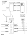
- FIG.1 A diagram of an 8 port MPA is shown in Fig.1 , having eight input ports p1-p8 and eight output ports q1-q8. It comprises a set of 3 columns t, x, y of 4 input hybrids A-M, a single column A of 8 amplifiers A1-A8, and a set of 3 columns t',x',y', of 4 output hybrids a-m.
- the MPA also includes a set of gain and phase adjusters G, ⁇ , for separate adjustment of each amplifier.
- FIG.2 A circuit definition of an hybrid (input or output hybrid) is presented in Fig.2 .
- the input and output signals, p 1 & p 2 and q 1 & q 2 are assumed to be complex.
- the described embodiments of the invention relate to adjustment of such gain and phase adjusters.
- communications signals that occur during normal use of the MPA are employed. These signals are sensed at the MPA outputs and downconverted to bring the sensed MPA outputs to baseband, ie. just the modulated signal that is going through the MPA, not the carrier.
- a digital model off-line is employed in the preferred embodiments and tuned as desired.
- the model is based on the perfect matrix of the MPA with additional terms to produce the same result as the best MPA that can be built.
- the digital model may be run in a ground based computer and all that has to be sent to the satellite, via a telemetry link, which may be a communications channel of the satellite reserved for system functions, are the required gain and phase settings for each MPA.
- the communication signal inputs to the MPAs are available in the ground station, since they are to be up-linked to the satellite.
- the only elements needed on the satellite are the sensing means whereby the MPA outputs are sensed.
- an inverse matrix model is located onboard the satellite. Rather than have an inverse for each MPA, a co-ax switch network (small signal level switches) "polls" a single inverse matrix round the MPAs as each is required to be adjusted. This minimises downconversion circuitry and inverse matrix circuitry.
- FIG. 3 is a schematic demonstrating a principle of operation of the invention
- inputs A-D are applied to an MPA 2.
- Outputs D-A which are amplified versions of the inputs, are sensed as at 4 and applied to a model 6 of MPA 2, in the sense that it is an inverse or reverse matrix, which accepts senses inputs D-A, and provides as outputs, signals corresponding to original input signals A-D, except that they are polluted with cross-talk contributions a, b, c, d from the other input signals.
- these corresponding signals are represented as A +b +c + d, B + a + c + d, C + a + b + d, D + a + b + c.
- Inverse matrix 6 is constituted by hybrid networks, but no amplifiers are provided. Matrix 6 may be regarded as part of an emulation mechanism, in that it imitates the operation of MPA 2, in order to reproduce the input signals.
- Input signals A-D are communications signals that occur during regular use of the communications satellite, and are modulated onto an RF carrier so as to be positioned in the appropriate microwave band.
- the signals are down-converted at 8 in order to bring the signals down to base band, and in order to reduce the requirements of processing circuitry.
- the processing circuitry is indicated generally as emulator 10, in dotted lines.
- a selector switch 12 couples the selected MPA 2 to emulator 10, in a sequential process in which each MPA is adjusted.
- Emulator 10 includes reverse MPA matrix 6, and the signals Input A + f 1 (B+C+D), Input B + f 2 (A+C+D), Input C + f 3 (B+A+D), Input D + f 4 (B+C+A), output from matrix 6, corresponding to input signals A-D, are input to a telemetry link 14 for transmission to a ground station 16.
- Link 14 may comprise a communications channel reserved for system functions. Prior to transmission, the input signals A-D are applied to link 14 on line 18 and an error measurement function calculates % values for the wanted and unwanted signals. These are telemetered to the ground station.
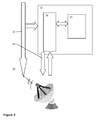
- the ground station 16 is shown in more detail in Figure 5 , as including an uplink antenna 20 for transmitting uplink signals on lines 22, and for supporting telemetry link 14.
- Uplink signals on line 22 and cross-talk component signals on link 14 are applied to a digital signal processor 24.
- Processor 24 includes a spectrum analysis FFT processor 26, which analyses the cross-talk contributions in terms of their frequency components.
- Processor 24 also includes a model 28 of MPA 2. The processor operates by modifying the characteristics of the model 28 to determine what characteristics would result in the actual cross-talk components f 1 - f 4 observed. Once having determined the current characteristics of MPA 2, adjustments may be determined to improve the isolation characteristics of MPA 2, and to reduce cross-talk components f 1 -f 4 .
- Necessary command signals to gain and phase adjusters within MPA 2 are applied via telemetry link 14 to command line 30 within the satellite, as shown in Figure 4 .
- Selector switch 32 applies the command signals to the MPA currently under test.
- DSP processor 24 receives the input signals A-D via line 18 and a selector switch 34, which operates synchronously with switches 12, 32.
- DSP processor 24 operates in the same manner as described in the first embodiment and provides analysis result signals to an MPA control and adjustment function 36, which translates the analysis results to gain and phase adjustment signals for the phase and gain adjusters within MPA 2.
Landscapes
- Engineering & Computer Science (AREA)
- Power Engineering (AREA)
- Physics & Mathematics (AREA)
- Nonlinear Science (AREA)
- Radio Relay Systems (AREA)
- Amplifiers (AREA)
Abstract
In order to maintain isolation of signals within a multiport amplifier of a communications satellite and to reduce cross-talk components, by monitoring communications signals passing through the multiport amplifier, output signals of the multiport amplifier are sensed and downconverted to baseband, and applied to an emulator mechanism (10) of the multiport amplifier. The emulator mechanism (10) comprises a reverse matrix (6) of the multiport amplifier, which recovers the input signals of the multiport amplifier together with cross-talk components, and a digital signal processor which carries out a frequency analysis of the cross-talk components by means of an FFT, and employs a digital model of the multiport amplifier to determine the state of the multiport amplifier which gives rise to such cross-talk components. The digital signal processor may be located at a ground station to which communication is made via a telemetry link.
Description
- This invention relates to multiport amplifiers for use within a satellite communication system, and specifically to a method and apparatus for maintaining isolation within multiport amplifiers.
- In Alan Couchman, Daryl Jones, "Multiport Amplifiers for Ka-band Multi-beam Payloads with Amplitude/Phase Compensation", Proceedings of the The 13th Ka and Broadband Communications Conference, Turin Italy, September 24-26, 2007, pp.527-534, there is described multiport amplifiers (MPAs) as a means for enhancing the flexibility of Ka-band multi-beam payloads. However, at Ka-band maintenance of tracking within the MPA becomes highly challenging. A solution is the use of feedback loops located at specific points within the MPA to detect tracking errors and provide compensation. Errors are detected through measurements at "null points" in the MPA output network, with zero power corresponding to accurate tracking. The feedback loops adjust the MPA phase/gains such that the levels at these points are maintained at zero. The scheme operates with a pilot signal for null detection injected at one of the MPA inputs. The signal may be generated onboard and would be located outside the normal traffic space ensuring that the scheme would be non-invasive.
- Whilst this solution is very effective at maintaining isolation, nevertheless it employs a significant amount of onboard hardware and on-board processing requirements. Since such requirements are at a premium in telecommunication satellites, further improvements in maintaining isolation within MPAs may be desirable.
- An MPA is a well-known power amplifier device used for satellite communications, which operates at the microwave frequency bands. An MPA includes a number N of similar amplifier units (TWT or solid state) in parallel, each having a power P, so that each input signal is amplified equally by each amplifier, to increase the power of each output signal by a factor N, to PxN. N input ports and N output ports are provided, so that an input signal on one input port is routed to the corresponding output port. The input ports are connected to the amplifier units by a low power input network (INET) that may be implemented in any convenient transmission line technology that is appropriate to the circumstances, e.g. microstrip, stripline, coaxial cable, or waveguide. The output ports are connected to the amplifier units by a high power output network (ONET) that is implemented typically using low loss transmission line technology. The ONET is mathematically a reciprocal of the INET, so that a signal presented to the nth input is directed to the nth output. Each network comprises an array of signal dividing waveguide devices. Butler matrices or networks comprising just hybrid devices are normally used for signal division, because they have convenient gain and phase shift properties. A hybrid is a four port signal dividing device comprising two inputs and two outputs, with selective 90° phase shifts; this phase difference may be exploited to improve the isolation characteristics of the networks. However other hybrids and other signal splitting devices may be used which may have 180° phase difference.
- The great advantage of an MPA is that in providing access for each input port equally to each amplifier, the accessible power available to each port is N x P, where P is the power of each individual amplifier. Thus the MPA embodies a high degree of flexibility, providing a wide range of output power which can be shared dynamically and in a highly flexible manner between the N inputs (or downlink beams). However a concomitant problem with an MPA is that of cross-talk between MPA output ports, and in general a lack of isolation between signals routed through the MPA.
- It is an object of the present invention to provide a multiport amplifier for a communications satellite with a method and means for maintaining isolation between signals routed through the multiport amplifier.
- For the purposes of the present specification, a multiport amplifier is defined as comprising a plurality of microwave power amplifier units, a plurality of input ports and a plurality of output ports, the input ports being connected to said amplifier units by an input signal dividing network, and the output ports being connected to said amplifier units by an output signal dividing network, so that an input signal at any input port is amplified, equally in normal or typical circumstances, by all amplifier units, and then recombined into an output signal at an output port: such multiport amplifier will be referred to as a "multiport amplifier as defined herein".
- In a first aspect, the invention provides a method of maintaining isolation of signals within a multiport amplifier of a communications satellite, the multiport amplifier comprising a plurality of microwave power amplifier units, a plurality of input ports and a plurality of output ports, the input ports being connected to said amplifier units by an input signal dividing network, and the output ports being connected to said amplifier units by an output signal dividing network, so that an input signal at any input port is amplified by all amplifier units, and then recombined into an output signal at an output port, the method comprising:
- providing at least one of said amplifier units with gain adjusting means and phase adjusting means, ,
- injecting input signals into at least some of said input ports, and detecting resultant output signals at at least some of said output ports,
- providing detected versions of said output signals to a multiport amplifier emulation means, said emulation means assessing cross-talk components within said detected versions, and in response thereto issuing as required adjusting commands to said gain adjusting means and/or phase adjusting means.
- In a further aspect, the invention provides a multiport amplifier for a oommunications satellite, comprising a plurality of microwave power amplifier units, a plurality of input ports and a plurality of output ports, the input ports being connected to said amplifier units by an input signal dividing network, the output ports being connected to said amplifier units by an output signal dividing network, so that an input signal at any input port is amplified, by all amplifier units, and then recombined into an output signal at an output port, and at least one of said amplifier units having gain adjusting means and phase adjusting means, means for detecting output signals at said output ports and for providing detected versions of said corresponding output signals to a multiport amplifier emulation means, said emulation means being arranged to assess cross-talk components within said detected versions, and being arranged to provide adjusting commands to said gain adjusting means and/or phase adjusting means.
- Since in accordance with the present invention, the condition of the multiport amplifier may be assessed and adjusted as required using communications input signals and output signals that occur in use of the multiport amplifier, it is unnecessary to provide and detect specific sequences of pilot tones, in contrast to the proposal of the above referenced paper. Nevertheless, the present invention may operate with pilot tones, if that is desired.
- The invention includes the feature of a multiport amplifier emulation means, which imitates certain aspects, or at least one aspect, of the multiport amplifier, in order to make an assessment of the output signals. Since it is well-known that a multiport amplifier may be represented as a number of matrices (see for example the above referenced paper), this provides a basis for making an emulator, and this may be done in analog form, in digital form, or a mixture of the two.
In one arrangement, the emulation means may be located within the communications satellite, and includes a reverse matrix of the multiport amplifier, which accepts said detected versions and provides outputs corresponding to said input signals. (In analog form, such reverse matrix may comprise two matrices of hybrids, corresponding to the INET and ONET matrices of the MPA, but without the amplifiers).. These corresponding signals will however be distorted to an extent depending on cross-talk contributions arising from within the multiport amplifier. Such corresponding signals may be applied to a signal processing means, preferably a digital signal processor, in addition to the actual input signals, and an assessment is carried out of the cross-talk contributions. Essentially the signal processor may carry out a spectrum analysis of the cross-talk contributions, and estimate a condition of the MPA, that would produce such cross-talk contributions. To do this, the signal processor may incorporate a model of the MPA to which virtual inputs may be applied and virtual outputs, together with cross-talk components, measured. The signal processor may therefore be regarded as an emulator, in the sense that it imitates an MPA. This may result in certain conclusions as to required phase and gain adjustments to the multiport amplifier. The present invention recognizes that since signal analysis is required of real communications signals then some form of frequency dependent analysis will need to be performed to process the various unwanted contributions that appear. This function would enable a simple comparison of the components coming back with what went in. Frequency components not present in the input signal must have come from the other channels. Although the frequency content will vary over time, as the signal content changes, the present invention recognizes that if analysis is carried out at baseband on the modulation signal downconverted from RF, then an FFT based approach may be employed, which is manageable at baseband in terms of processing requirements. - Nevertheless, since the provision of a digital signal processor may add significantly to the on-board processing payload of the satellite, it is preferred in accordance with a further feature of the invention to provide the emulation means, at least in part, at a ground station, and to provide a telemetry link to the ground station. In a preferred arrangement, said reverse matrix means is retained in the satellite, in order to extract the cross-talk contributions from the output signals, and these contributions are transmitted via the telemetry link to signal processing means located on the ground station. The ground station in addition requires knowledge of the input signals. These may conveniently be provided by monitoring the uplink transmission signals at the ground station, which will be the basis of the inputs to the multiport amplifier.
- In a further feature of the invention, a plurality of multiport amplifiers may be monitored and adjusted employing said emulation means. Selector switch means are provided to sequentially provide detected versions of the output signals of the various multiport amplifiers to the emulation means. Similarly selector switches are provided to selectively route adjustment commands to the respective multiport amplifiers.
- Preferred embodiments of the invention will now be described with reference to the accompanying drawings, wherein:
-
Figure 1 is a block diagram of an 8 port multiport amplifier (MPA) of known construction for use in a telecommunications satellite; -
Figure 2 is a schematic of a hybrid used in the MPA ofFigure 1 ; -
Figure 3 is a block diagram illustrating the concept of the present invention; -
Figure 4 is a block diagram of a first embodiment of the invention, employing a telemetry link to ground station emulation circuits for a multiport amplifier; -
Figure 5 is a conceptual diagram of the ground station of the second embodiment; and -
Figure 6 is a block diagram of a second embodiment of the invention, employing on-board emulation circuits for a multiport amplifier; - A diagram of an 8 port MPA is shown in
Fig.1 , having eight input ports p1-p8 and eight output ports q1-q8. It comprises a set of 3 columns t, x, y of 4 input hybrids A-M, a single column A of 8 amplifiers A1-A8, and a set of 3 columns t',x',y', of 4 output hybrids a-m. The MPA also includes a set of gain and phase adjusters G, Θ, for separate adjustment of each amplifier. - A circuit definition of an hybrid (input or output hybrid) is presented in
Fig.2 . The input and output signals, p1 & p2 and q1 & q2, are assumed to be complex. The hybrid transfer function is represented thus:
where C11, C12, C21, C22 are all invariable complex coefficients which can be represented as follows:
- Ideally for a perfect hybrid all r = 1/√2, and all θ = 0, and the transfer matrix becomes:

- The amplifiers are assumed to be perfectly linear with complex gain A, represented by function:

- Ideally in a MPA transponder all amplifiers are matched and have the same value of G and Θ. However in practice, over time values of G and Θ will change, and correction is necessary, otherwise significant cross-talk components may be present in MPA output signals. Phase and Gain adjuster circuits are placed in the individual signal paths immediately before the amplifiers A (not shown).
- The described embodiments of the invention relate to adjustment of such gain and phase adjusters. Rather than using injected pilot tones, communications signals that occur during normal use of the MPA are employed. These signals are sensed at the MPA outputs and downconverted to bring the sensed MPA outputs to baseband, ie. just the modulated signal that is going through the MPA, not the carrier.
- A digital model off-line is employed in the preferred embodiments and tuned as desired. The model is based on the perfect matrix of the MPA with additional terms to produce the same result as the best MPA that can be built. There is an in-orbit tune up phase as the satellite is commissioned. The digital model may be run in a ground based computer and all that has to be sent to the satellite, via a telemetry link, which may be a communications channel of the satellite reserved for system functions, are the required gain and phase settings for each MPA. The communication signal inputs to the MPAs are available in the ground station, since they are to be up-linked to the satellite. The only elements needed on the satellite are the sensing means whereby the MPA outputs are sensed. To minimise the data to be sent to the ground based model, an inverse matrix model is located onboard the satellite. Rather than have an inverse for each MPA, a co-ax switch network (small signal level switches) "polls" a single inverse matrix round the MPAs as each is required to be adjusted. This minimises downconversion circuitry and inverse matrix circuitry.
- By sensing the outputs and by running an emulator process off-line then the auto tune up process does not interfere with normal operation of the satellite. In the event that the tune up system fails there would not be any catastrophic loss of communications capacity.
- Referring now to
Figure 3 , which is a schematic demonstrating a principle of operation of the invention, inputs A-D are applied to anMPA 2. Outputs D-A, which are amplified versions of the inputs, are sensed as at 4 and applied to amodel 6 ofMPA 2, in the sense that it is an inverse or reverse matrix, which accepts senses inputs D-A, and provides as outputs, signals corresponding to original input signals A-D, except that they are polluted with cross-talk contributions a, b, c, d from the other input signals. Thus these corresponding signals are represented as A +b +c + d, B + a + c + d, C + a + b + d, D + a + b + c.Inverse matrix 6 is constituted by hybrid networks, but no amplifiers are provided.Matrix 6 may be regarded as part of an emulation mechanism, in that it imitates the operation ofMPA 2, in order to reproduce the input signals. - Referring now to
Figures 4 and5 , these are block diagrams of a first embodiment of the invention, where similar parts to those ofFigure 3 are denoted by the same reference numeral. Input signals A-D are communications signals that occur during regular use of the communications satellite, and are modulated onto an RF carrier so as to be positioned in the appropriate microwave band. In order to monitor the sensed output signals D-A, the signals are down-converted at 8 in order to bring the signals down to base band, and in order to reduce the requirements of processing circuitry. The processing circuitry is indicated generally asemulator 10, in dotted lines. In the event that it is desired to monitor and adjust several MPAs within the communications satellite, aselector switch 12 couples the selectedMPA 2 toemulator 10, in a sequential process in which each MPA is adjusted. -
Emulator 10 includesreverse MPA matrix 6, and the signals Input A + f1(B+C+D), Input B + f2(A+C+D), Input C + f3(B+A+D), Input D + f4(B+C+A), output frommatrix 6, corresponding to input signals A-D, are input to atelemetry link 14 for transmission to aground station 16.Link 14 may comprise a communications channel reserved for system functions. Prior to transmission, the input signals A-D are applied to link 14 online 18 and an error measurement function calculates % values for the wanted and unwanted signals. These are telemetered to the ground station. - The
ground station 16 is shown in more detail inFigure 5 , as including anuplink antenna 20 for transmitting uplink signals on lines 22, and for supportingtelemetry link 14. Uplink signals on line 22 and cross-talk component signals onlink 14 are applied to adigital signal processor 24.Processor 24 includes a spectrumanalysis FFT processor 26, which analyses the cross-talk contributions in terms of their frequency components.Processor 24 also includes amodel 28 ofMPA 2. The processor operates by modifying the characteristics of themodel 28 to determine what characteristics would result in the actual cross-talk components f1- f4 observed. Once having determined the current characteristics ofMPA 2, adjustments may be determined to improve the isolation characteristics ofMPA 2, and to reduce cross-talk components f1-f4. Necessary command signals to gain and phase adjusters withinMPA 2 are applied viatelemetry link 14 tocommand line 30 within the satellite, as shown inFigure 4 .Selector switch 32 applies the command signals to the MPA currently under test. - Referring now to the second embodiment shown in
Figure 6 , similar parts to those ofFigures 4 and5 are denoted by the same reference numeral. In this second embodiment, all processing is carried out on-board the satellite, anddigital signal processor 24 is directly coupled to receive the outputs ofreverse matrix 6. Inaddition DSP processor 24 receives the input signals A-D vialine 18 and aselector switch 34, which operates synchronously withswitches DSP processor 24 operates in the same manner as described in the first embodiment and provides analysis result signals to an MPA control and adjustment function 36, which translates the analysis results to gain and phase adjustment signals for the phase and gain adjusters withinMPA 2.
Claims (12)
- A method of maintaining isolation of signals within a multiport amplifier of a communications satellite, the multiport amplifier comprising a plurality of microwave power amplifier units, a plurality of input ports and a plurality of output ports, the input ports being connected to said amplifier units by an input signal dividing network, and the output ports being connected to said amplifier units by an output signal dividing network, so that an input signal at any input port is amplified by all amplifier units, and then recombined into an output signal at an output port, the method comprising:providing at least one of said amplifier units with gain adjusting means and phase adjusting means, ,injecting input signals into at least some of said input ports, and detecting resultant output signals at at least some of said output ports,providing detected versions of said output signals to a multiport amplifier emulation means, said emulation means assessing cross-talk components within said detected versions, and in response thereto issuing as required adjusting commands to said gain adjusting means and/or phase adjusting means.
- A method according to claim 1, wherein said emulation means includes a reverse matrix of the multiport amplifier, which accepts said detected versions and provides as outputs, signals corresponding to said input signals
- A method according to claim 1 or 2, including digitally processing said corresponding signals within said emulation means in order to assess said cross-talk components, including making a frequency analysis of said cross-talk components.
- A method according to claim 3, wherein said emulation means includes a digital representation of said multiport amplifier, wherein said cross-talk components are assessed.
- A method according to claim 4 or 5, wherein said digital processing takes place on-board the communications satellite.
- A method according to claim 4 or 5, including providing a telemetry link, and said digital processing takes place at a ground station.
- A method according to any preceding claim, wherein said input signals comprise communications signals modulated on a carrier wave, and the method comprising downconverting the detected output signals to provide said detected versions.
- A method according to any preceding claim, including providing a plurality of multiport amplifiers, and selecting each of said multiport amplifiers in sequence for said gain and/or phase adjusting.
- A multiport amplifier for a communications satellite, comprising a plurality of microwave power amplifier units, a plurality of input ports and a plurality of output ports, the input ports being connected to said amplifier units by an input signal dividing network, the output ports being connected to said amplifier units by an output signal dividing network, so that an input signal at any input port is amplified, by all amplifier units, and then recombined into an output signal at an output port, and at least one of said amplifier units having gain adjusting means and phase adjusting means, means for detecting output signals at said output ports and for providing detected versions of said corresponding output signals to a multiport amplifier emulation means, said emulation means being arranged to assess cross-talk components within said detected versions, and being arranged to provide adjusting commands to said gain adjusting means and/or phase adjusting means.
- Apparatus according to claim 10, wherein said emulation means comprises a reverse matrix of the multiport amplifier, which accepts said detected versions and provides as outputs, signals corresponding to said input signals
- Apparatus according to claim 10 or 11, wherein said emulation means comprises a digital signal processing means for carrying out an assessment of said cross-talk components.
- Apparatus according to claim 12, wherein said digital processing means includes an FFT means for carrying out a frequency analysis of said cross-talk components, and a digital representation of said multiport amplifier in which said cross-talk components are assessed.
Priority Applications (7)
| Application Number | Priority Date | Filing Date | Title |
|---|---|---|---|
| EP07270080A EP2073381A1 (en) | 2007-12-21 | 2007-12-21 | Multiport amplifiers in communications satellites |
| PCT/EP2008/068026 WO2009080752A1 (en) | 2007-12-21 | 2008-12-19 | Multiport amplifiers in communications satellites |
| RU2010130426/08A RU2488951C2 (en) | 2007-12-21 | 2008-12-19 | Multiport amplifiers in communication satellites |
| CA2708503A CA2708503C (en) | 2007-12-21 | 2008-12-19 | Multiport amplifiers in communications satellites |
| EP08865694.7A EP2223429B1 (en) | 2007-12-21 | 2008-12-19 | Multiport amplifiers in communications satellites |
| JP2010538760A JP5276115B2 (en) | 2007-12-21 | 2008-12-19 | Multiport amplifier for communication satellite |
| US12/809,788 US8463204B2 (en) | 2007-12-21 | 2008-12-19 | Multiport amplifiers in communications satellites |
Applications Claiming Priority (1)
| Application Number | Priority Date | Filing Date | Title |
|---|---|---|---|
| EP07270080A EP2073381A1 (en) | 2007-12-21 | 2007-12-21 | Multiport amplifiers in communications satellites |
Publications (1)
| Publication Number | Publication Date |
|---|---|
| EP2073381A1 true EP2073381A1 (en) | 2009-06-24 |
Family
ID=39365585
Family Applications (1)
| Application Number | Title | Priority Date | Filing Date |
|---|---|---|---|
| EP07270080A Ceased EP2073381A1 (en) | 2007-12-21 | 2007-12-21 | Multiport amplifiers in communications satellites |
Country Status (1)
| Country | Link |
|---|---|
| EP (1) | EP2073381A1 (en) |
Cited By (3)
| Publication number | Priority date | Publication date | Assignee | Title |
|---|---|---|---|---|
| US7965136B2 (en) | 2008-12-12 | 2011-06-21 | Astrium Limited | Multiport amplifier adjustment |
| FR2989545A1 (en) * | 2012-04-17 | 2013-10-18 | Eutelsat Sa | METHOD FOR TESTING AN AMPLIFICATION PATH OF A REPEATER OF A TELECOMMUNICATIONS SATELLITE |
| US10320064B2 (en) | 2016-02-04 | 2019-06-11 | Space Systems/Loral, Llc | Multiport amplifiers (MPAs) using output filtering to improve performance over life |
Citations (4)
| Publication number | Priority date | Publication date | Assignee | Title |
|---|---|---|---|---|
| US6006111A (en) * | 1997-10-08 | 1999-12-21 | Nortel Networks Corporation | Self-balancing matrix amplifier |
| WO2005029875A2 (en) * | 2003-09-24 | 2005-03-31 | Nortel Networks Limited | Digital convertible radio snr optimization |
| JP2005269043A (en) * | 2004-03-17 | 2005-09-29 | Nippon Telegr & Teleph Corp <Ntt> | Multiport amplifier and method for compensating distortion |
| JP2006345066A (en) * | 2005-06-07 | 2006-12-21 | Matsushita Electric Ind Co Ltd | Hybrid distortion compensation apparatus, transmitter, mobile communication terminal, and hybrid distortion compensation method |
-
2007
- 2007-12-21 EP EP07270080A patent/EP2073381A1/en not_active Ceased
Patent Citations (4)
| Publication number | Priority date | Publication date | Assignee | Title |
|---|---|---|---|---|
| US6006111A (en) * | 1997-10-08 | 1999-12-21 | Nortel Networks Corporation | Self-balancing matrix amplifier |
| WO2005029875A2 (en) * | 2003-09-24 | 2005-03-31 | Nortel Networks Limited | Digital convertible radio snr optimization |
| JP2005269043A (en) * | 2004-03-17 | 2005-09-29 | Nippon Telegr & Teleph Corp <Ntt> | Multiport amplifier and method for compensating distortion |
| JP2006345066A (en) * | 2005-06-07 | 2006-12-21 | Matsushita Electric Ind Co Ltd | Hybrid distortion compensation apparatus, transmitter, mobile communication terminal, and hybrid distortion compensation method |
Non-Patent Citations (1)
| Title |
|---|
| ALAN COUCHMAN; DARYL JONES: "Multiport Amplifiers for Ka-band Multi-beam Payloads with Amplitude/Phase Compensation", PROCEEDINGS OF THE THE 13TH KA AND BROADBAND COMMUNICATIONS CONFERENCE, 24 September 2007 (2007-09-24), pages 527 - 534 |
Cited By (4)
| Publication number | Priority date | Publication date | Assignee | Title |
|---|---|---|---|---|
| US7965136B2 (en) | 2008-12-12 | 2011-06-21 | Astrium Limited | Multiport amplifier adjustment |
| FR2989545A1 (en) * | 2012-04-17 | 2013-10-18 | Eutelsat Sa | METHOD FOR TESTING AN AMPLIFICATION PATH OF A REPEATER OF A TELECOMMUNICATIONS SATELLITE |
| EP2654222A1 (en) * | 2012-04-17 | 2013-10-23 | Eutelsat S.A. | Method for testing an amplification channel of a repeater of a telecommunications satellite |
| US10320064B2 (en) | 2016-02-04 | 2019-06-11 | Space Systems/Loral, Llc | Multiport amplifiers (MPAs) using output filtering to improve performance over life |
Similar Documents
| Publication | Publication Date | Title |
|---|---|---|
| EP2223429B1 (en) | Multiport amplifiers in communications satellites | |
| RU2513696C2 (en) | Tuning multiport amplifier | |
| US10187076B2 (en) | Broadband digital beam forming system including wavefront multiplexers and narrowband digital beam forming modules | |
| US8953728B2 (en) | System for processing data streams | |
| US6133868A (en) | System and method for fully self-contained calibration of an antenna array | |
| EP2145386B1 (en) | Multiport amplifiers in communications satellites | |
| EP1506615B1 (en) | Method and apparatus for error compensation in a hybrid matrix amplification system | |
| US9735742B2 (en) | Multi-port amplifier utilizing an adjustable delay function | |
| US6233433B1 (en) | Apparatus and method of testing multi-beam satellite repeater in-orbit from a single ground station using a sampling and combining matrix | |
| US6535546B1 (en) | Method and apparatus for determining characteristics of components of a communication channel under load | |
| EP2073381A1 (en) | Multiport amplifiers in communications satellites | |
| US10624051B2 (en) | System for measuring multi-port amplifier errors | |
| US10541656B1 (en) | Method and apparatus for calibration and equalization of multiport amplifiers (MPAs) | |
| US20230216212A1 (en) | Phased array antenna apparatus and method | |
| Migl et al. | Time and cost efficient satellite payload measurements | |
| Rathnakara et al. | In-orbit testing of satellite communication payloads |
Legal Events
| Date | Code | Title | Description |
|---|---|---|---|
| PUAI | Public reference made under article 153(3) epc to a published international application that has entered the european phase |
Free format text: ORIGINAL CODE: 0009012 |
|
| AK | Designated contracting states |
Kind code of ref document: A1 Designated state(s): AT BE BG CH CY CZ DE DK EE ES FI FR GB GR HU IE IS IT LI LT LU LV MC MT NL PL PT RO SE SI SK TR |
|
| AX | Request for extension of the european patent |
Extension state: AL BA HR MK RS |
|
| STAA | Information on the status of an ep patent application or granted ep patent |
Free format text: STATUS: THE APPLICATION HAS BEEN REFUSED |
|
| 18R | Application refused |
Effective date: 20090711 |