EP2073073A1 - Process cartridge and image forming apparatus - Google Patents
Process cartridge and image forming apparatus Download PDFInfo
- Publication number
- EP2073073A1 EP2073073A1 EP08254003A EP08254003A EP2073073A1 EP 2073073 A1 EP2073073 A1 EP 2073073A1 EP 08254003 A EP08254003 A EP 08254003A EP 08254003 A EP08254003 A EP 08254003A EP 2073073 A1 EP2073073 A1 EP 2073073A1
- Authority
- EP
- European Patent Office
- Prior art keywords
- toner
- image carrier
- process cartridge
- cleaning
- resin
- Prior art date
- Legal status (The legal status is an assumption and is not a legal conclusion. Google has not performed a legal analysis and makes no representation as to the accuracy of the status listed.)
- Granted
Links
- 238000000034 method Methods 0.000 title claims abstract description 57
- 230000008569 process Effects 0.000 title claims abstract description 56
- 238000004140 cleaning Methods 0.000 claims abstract description 55
- 238000012546 transfer Methods 0.000 claims abstract description 12
- 239000011347 resin Substances 0.000 claims description 31
- 229920005989 resin Polymers 0.000 claims description 31
- 239000000956 alloy Substances 0.000 claims description 4
- 229910045601 alloy Inorganic materials 0.000 claims description 4
- 238000001746 injection moulding Methods 0.000 claims description 4
- YCKRFDGAMUMZLT-UHFFFAOYSA-N Fluorine atom Chemical compound [F] YCKRFDGAMUMZLT-UHFFFAOYSA-N 0.000 claims description 3
- 239000004962 Polyamide-imide Substances 0.000 claims description 3
- 239000011737 fluorine Substances 0.000 claims description 3
- 229910052731 fluorine Inorganic materials 0.000 claims description 3
- 229920006122 polyamide resin Polymers 0.000 claims description 3
- 229920002312 polyamide-imide Polymers 0.000 claims description 3
- 229920013716 polyethylene resin Polymers 0.000 claims description 3
- 229920001721 polyimide Polymers 0.000 claims description 3
- 239000009719 polyimide resin Substances 0.000 claims description 3
- 239000004734 Polyphenylene sulfide Substances 0.000 claims description 2
- 229920000069 polyphenylene sulfide Polymers 0.000 claims description 2
- 230000015572 biosynthetic process Effects 0.000 description 8
- 238000007599 discharging Methods 0.000 description 7
- 230000003014 reinforcing effect Effects 0.000 description 5
- 229930182556 Polyacetal Natural products 0.000 description 4
- 238000010586 diagram Methods 0.000 description 4
- 229920006324 polyoxymethylene Polymers 0.000 description 4
- 239000003086 colorant Substances 0.000 description 3
- NJLLQSBAHIKGKF-UHFFFAOYSA-N dipotassium dioxido(oxo)titanium Chemical compound [K+].[K+].[O-][Ti]([O-])=O NJLLQSBAHIKGKF-UHFFFAOYSA-N 0.000 description 3
- 230000008570 general process Effects 0.000 description 3
- 239000011521 glass Substances 0.000 description 3
- 239000010445 mica Substances 0.000 description 3
- 229910052618 mica group Inorganic materials 0.000 description 3
- 230000002093 peripheral effect Effects 0.000 description 3
- 239000000454 talc Substances 0.000 description 3
- 229910052623 talc Inorganic materials 0.000 description 3
- 239000002699 waste material Substances 0.000 description 3
- PPBRXRYQALVLMV-UHFFFAOYSA-N Styrene Chemical compound C=CC1=CC=CC=C1 PPBRXRYQALVLMV-UHFFFAOYSA-N 0.000 description 2
- 230000009471 action Effects 0.000 description 2
- 230000008901 benefit Effects 0.000 description 2
- 239000000463 material Substances 0.000 description 2
- 230000032258 transport Effects 0.000 description 2
- 239000004721 Polyphenylene oxide Substances 0.000 description 1
- 239000004743 Polypropylene Substances 0.000 description 1
- 239000004676 acrylonitrile butadiene styrene Substances 0.000 description 1
- 229920000122 acrylonitrile butadiene styrene Polymers 0.000 description 1
- XECAHXYUAAWDEL-UHFFFAOYSA-N acrylonitrile butadiene styrene Chemical compound C=CC=C.C=CC#N.C=CC1=CC=CC=C1 XECAHXYUAAWDEL-UHFFFAOYSA-N 0.000 description 1
- 239000000969 carrier Substances 0.000 description 1
- 210000000078 claw Anatomy 0.000 description 1
- 238000010276 construction Methods 0.000 description 1
- 238000005516 engineering process Methods 0.000 description 1
- 238000012423 maintenance Methods 0.000 description 1
- 238000012986 modification Methods 0.000 description 1
- 230000004048 modification Effects 0.000 description 1
- 239000004745 nonwoven fabric Substances 0.000 description 1
- 229920005668 polycarbonate resin Polymers 0.000 description 1
- 239000004431 polycarbonate resin Substances 0.000 description 1
- 229920001955 polyphenylene ether Polymers 0.000 description 1
- 229920006380 polyphenylene oxide Polymers 0.000 description 1
- -1 polypropylene Polymers 0.000 description 1
- 229920001155 polypropylene Polymers 0.000 description 1
- 238000012545 processing Methods 0.000 description 1
- 238000011144 upstream manufacturing Methods 0.000 description 1
- 239000002759 woven fabric Substances 0.000 description 1
Images


Classifications
-
- G—PHYSICS
- G03—PHOTOGRAPHY; CINEMATOGRAPHY; ANALOGOUS TECHNIQUES USING WAVES OTHER THAN OPTICAL WAVES; ELECTROGRAPHY; HOLOGRAPHY
- G03G—ELECTROGRAPHY; ELECTROPHOTOGRAPHY; MAGNETOGRAPHY
- G03G21/00—Arrangements not provided for by groups G03G13/00 - G03G19/00, e.g. cleaning, elimination of residual charge
- G03G21/16—Mechanical means for facilitating the maintenance of the apparatus, e.g. modular arrangements
- G03G21/18—Mechanical means for facilitating the maintenance of the apparatus, e.g. modular arrangements using a processing cartridge, whereby the process cartridge comprises at least two image processing means in a single unit
- G03G21/1803—Arrangements or disposition of the complete process cartridge or parts thereof
- G03G21/1817—Arrangements or disposition of the complete process cartridge or parts thereof having a submodular arrangement
- G03G21/1821—Arrangements or disposition of the complete process cartridge or parts thereof having a submodular arrangement means for connecting the different parts of the process cartridge, e.g. attachment, positioning of parts with each other, pressure/distance regulation
-
- G—PHYSICS
- G03—PHOTOGRAPHY; CINEMATOGRAPHY; ANALOGOUS TECHNIQUES USING WAVES OTHER THAN OPTICAL WAVES; ELECTROGRAPHY; HOLOGRAPHY
- G03G—ELECTROGRAPHY; ELECTROPHOTOGRAPHY; MAGNETOGRAPHY
- G03G21/00—Arrangements not provided for by groups G03G13/00 - G03G19/00, e.g. cleaning, elimination of residual charge
- G03G21/16—Mechanical means for facilitating the maintenance of the apparatus, e.g. modular arrangements
- G03G21/18—Mechanical means for facilitating the maintenance of the apparatus, e.g. modular arrangements using a processing cartridge, whereby the process cartridge comprises at least two image processing means in a single unit
- G03G21/1839—Means for handling the process cartridge in the apparatus body
- G03G21/1857—Means for handling the process cartridge in the apparatus body for transmitting mechanical drive power to the process cartridge, drive mechanisms, gears, couplings, braking mechanisms
Definitions
- the present invention relates to a process cartridge and an image forming apparatus using the process cartridge.
- an image forming apparatus such as a copying machine, a printer, a facsimile, and a multifunction product (MFP)
- a full-color image formation is widely spread.
- a tandem-type image forming apparatus having a plurality of image carriers with a highspeed processing is becoming the mainstream of the image forming field.
- an apparatus employing a process cartridge including an image carrier and at least one of a charging unit, a developing unit, and a cleaning unit is also known.
- the process cartridge is mounted on the main body of the image forming apparatus in a detachable manner, and can be taken out of the apparatus for its replacing work or maintenance work to avoid a work in a narrow space in the apparatus.
- a process cartridge including an image carrier and at least a cleaning unit
- toners removed by the cleaning unit are conveyed out of the cartridge.
- a conveying coil spring, a conveying coil, or a conveying screw as a conveying unit for conveying toners in the longitudinal direction of the cleaning member.
- a gear is provided which engages with a gear of the image carrier.
- a photosensitive drum 101 has a rotating shaft laterally supported between the side walls of the casing of the process cartridge and both axial ends are supported at the side walls of the casing.
- a cleaning blade (not shown) is fixed to the casing of the process cartridge with screws, the toners removed from the photosensitive drum 101 at the upstream side in the rotating direction of the photosensitive drum 101 are conveyed out by a conveying coil 102 in the longitudinal direction of the cleaning member and contained in a waste toner tank (not shown).
- the conveying coil 102 is inserted and held by a shaft 103 and rotatably supported at the casing through a sliding bearing 104, a gear 105 applying a driving force is fixed to the shaft 103 and rotatably held at the casing with an E-shaped fitting ring 106.
- the conventional process cartridge requires a number of parts, causing a problem of its cost with a bulky size.
- a process cartridge configured to be mounted on a main body of an image forming apparatus in a detachable manner.
- the process cartridge includes an image carrier on which a toner image is formed; a cleaning unit that cleans the image carrier by removing residual toner remained after transferring the toner image formed on the image carrier onto a transfer medium, which includes a cleaning member that removes the toner from the image carrier and a toner conveying unit that conveys the toner removed by the cleaning member in a longitudinal direction of the cleaning member, including a toner conveying member that makes a rotation to convey the toner removed by the cleaning member in a predetermined direction and a rotary supporting member that supports the toner conveying member at a predetermined position such that the toner conveying member can be rotated and makes a rotation with a driving force from outside; a side wall for supporting the image carrier such that the image carrier can be rotated; and an outer cover member having a surface parallel to the side wall.
- the side wall includes a through hole
- a process cartridge configured to be mounted on a main body of an image forming apparatus in a detachable manner.
- the process cartridge includes an image carrier on which a toner image is formed; a cleaning unit that cleans the image carrier by removing residual toner remained after transferring the toner image formed on the image carrier onto a transfer medium, which includes a cleaning member that removes the toner from the image carrier and a toner conveying unit that conveys the toner removed by the cleaning member in a longitudinal direction of the cleaning member, including a toner conveying member that makes a rotation to convey the toner removed by the cleaning member in a predetermined direction and a rotary supporting member that supports the toner conveying member at a predetermined position such that the toner conveying member can be rotated and makes a rotation with a driving force from outside; a side wall for supporting the image carrier such that the image carrier can be rotated; an outer cover member having a surface parallel to the side wall; and a holder for supporting
- Fig. 1 is a schematic diagram of an example of an image forming apparatus 1 that forms a full-color image employing a process cartridge according to the present invention.
- the image forming apparatus 1 includes image forming units 2Y, 2C, 2M, and 2K corresponding to four different colors, an intermediate transfer belt 10 arranged in opposition to the image forming units 2Y, 2C, 2M, and 2K, and a sheet feeding unit 20 for feeding a recording sheet.
- the image forming units 2Y, 2C, 2M, and 2K are used for developing yellow, cyan, magenta, and black, respectively.
- the configuration of the image forming unit 2K will be described as a representing one of the image forming units 2Y, 2C, 2M, and 2K because they have virtually the same configuration.
- Fig. 2 is a schematic diagram of a process cartridge 50k of the image forming apparatus 1.
- the image forming unit 2K includes a photosensitive drum 3K as an image carrier, a charging unit 4K, a developing unit 5K, and a cleaning unit 7K arranged in sequence along a rotating direction of the photosensitive drum 3K.
- An electrostatic latent image is formed according to image information by a writing light L from a writing unit 8 between the charging unit 4K and the developing unit 5K.
- a belt-like carrier may also be used instead of the drum-like carrier.
- the image forming unit 2K is made such that the photosensitive drum 3K, the charging unit 4K, the developing unit 5K, and the cleaning unit 7K arranged around the photosensitive drum 3K are constituted as a process cartridge 50K stored in a single cartridge.
- the photosensitive drum 3K is rotationally driven by a main motor (not shown), and when it is uniformly charged by the charging unit 4K, a writing process is executed.
- a target image is written according to digital image data from a control unit (not shown) to form an electrostatic latent image under application of the writing unit 8.
- the electrostatic latent image formed on the photosensitive drum 3K is developed by the developing unit 5K.
- toners adhere only to image portions of low electric potentials through an irradiation of the writing light, and toners are developed to form a toner image.
- the toner image of each of the colors is electrostatically transferred from the photosensitive drum 3k to the intermediate transfer belt 10 with an application of a bias having a polarity opposite to that of the toners to a primary transfer device constituted as a primary transfer roller 6k oppositely arranged against the photosensitive drums 3k. Then, the toner images of four colors are transferred onto the intermediate transfer belt 10 in a superimposed manner, and collectively transferred onto a recording sheet fed from the sheet feeding unit 20 by a secondary transfer roller 11.
- the sheet feeding unit 20 includes a sheet feeding cassette 21.
- the recording sheet fed from the sheet feeding cassette 21 is conveyed to a secondary transferring device by a pair of registration rollers 22 at an appropriate timing at which the toner images are transferred onto the intermediate transfer belt 10.
- the recording sheet passed through the transferring process is separated from a roller 12 and further conveyed toward a fixing unit 13.
- the toner images are fixed on the recording sheet when the recording sheet passes through a fixing nip constituted by rollers, and then the recording sheet is discharged to a sheet discharging tray 15 through sheet discharging rollers 14.
- the sheet discharging rollers 14 are used as switch-back conveying members when a duplex image formation is performed. That is, the image forming apparatus 1 is constructed to perform not only a single-sided image formation but also a duplex image formation. Therefore, in the case of the duplex image formation, the recording sheet after fixing the image formed thereon is once conveyed to the sheet discharging tray 15 by the sheet discharging rollers 14, and then the sheet discharging rollers 14 are rotated in the reverse direction with the trailing edge of the recording sheet being held between the rollers.
- the recording sheet is conveyed from the sheet discharging tray 15 to a reverse feeding path and fed toward the registration rollers 22 positioned at a merging part between the reverse feeding path and a feeding path from the sheet feeding cassette 21.
- a changing-over of the conveying paths for the recording sheet at the time of forming images at the single and the both sides is carried out by a conveying path changing-over claw arranged at the rear side of the fixing unit 13.
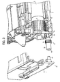
- Fig. 3 is a partial exploded perspective view of a process cartridge 50 according to a first embodiment of the present invention.
- a cleaning unit 7 arranged inside the process cartridge 50 includes a cleaning blade 70 and a conveying coil spring 71 for conveying toners removed from a photosensitive drum 3 by the cleaning blade 70 outside the process cartridge 50.
- the cleaning blade 70 is fixed with a screw 73 to a side wall 72.
- a rotary supporting member 74 On one end of the conveying coil spring 71, a rotary supporting member 74 is provided.
- the rotary supporting member 74 includes a connecting part 75 formed into a split pin shape that is inserted and connected to be contacted with the inner peripheral part of the conveying coil spring 71, a shaft part 76 subsequent to the connecting part 75 so as to hold a cylindrical seal member (not shown), a driving shaft 78 inserted into a shaft hole 77 formed at the side wall 72 of the cleaning unit 7 and rotatably supporting a position setting hole 80, and a gear 79 for transmitting a driving action of the conveying coil spring 71 arranged at the driving shaft 78. Further, the gear 79 directly receives a rotary driving force from a gear 31 of the photosensitive drum 3.
- the process cartridge 50 further includes an outer cover member 51, and the outer cover member 51 is provided with a pin 52 for use in position setting and supporting the rotary supporting member 74.
- the pin 52 oppositely faces against the driving shaft 78 at the extremity end of the rotary supporting member 74 and the surface of the driving shaft 78 opposing against the pin 52 is formed with the position setting hole 80 into which the pin 52 is rotatably fitted.
- the holding unit according to the first embodiment is constituted by the pin 52 and the position setting hole 80, the pin 52 is fitted into the position setting hole 80 at the time of assembling operation, thereby the conveying coil spring 71 can be positively supported and rotated in a high precision. Further, it may also be applicable that the holding unit has a configuration opposite to the aforesaid one, where the outer cover member 51 is provided with the position setting hole 80 and the rotary supporting member 74 is provided with the pin 52 inserted into the position setting hole 80.
- the cleaning unit 7 constituted as described above is operated such that the toners removed from the photosensitive drum 3 by the cleaning blade 70 are temporarily stored in a space where the conveying coil spring 71 is arranged, and the removed toners are transported in a direction in parallel with a longitudinal direction of the cleaning blade 70 under a rotation of the conveying coil spring 71. Then, the toners are transported out of the process cartridge 50 and stored in a waste toner tank not shown. Further, as means for conveying toners, either the conveying coil or a conveying screw may be used in place of the conveying coil spring 71.
- the rotary supporting member 74 is integrally molded through an injection molding process with polyacetal resin for the connecting part 75, the shaft part 76, the driving shaft 78, the gear 79 and the position setting hole 80 and the number of component parts is substantially reduced.
- the rotary supporting member 74 may be made of polyamide resin, fluorine resin, polyimide resin, polyamide-imide resin, polyphenylene sulfide resin, polyethylene resin, polypropylene resin and these alloy resins and the like.
- a reinforcing member either single or more of glass, potassium titanate, talc, mica, lewistonite and natural ores may be added and it is a general process to add these reinforcing members by 5% to 50%.
- cylindrical seal member supported by the shaft part 76 it is possible to use members made of foamed material, non-woven fabric and woven-fabric and the like.
- the outer cover member 51 has a hole for holding the rotating shaft inserted into the photosensitive drum 3 and a hole for holding the rotating shaft inserted into the developing unit 5 and an inter-shaft distance between the photosensitive drum 3 and the developing unit 5 is restricted by both holding holes. Then, the rotary supporting member 74 supporting the conveying coil spring 71 passes through a through hole 54 formed at a side wall 53 of the process cartridge 50, the pin 52 of the outer cover member 51 is fitted to the position setting hole 80, thereby assembled into the process cartridge 50.
- the outer cover member 51 and the side wall 53 of the process cartridge 50 are constituted by resin formed through an injection molding, polycarbonate resin, acrylonitrile-butadienestyrene resin, styrene resin, polyphenylene-ether resin, polyphenylene-oxide resin, polyether-terephthalate resin and these alloy resins and the like can be used, and additionally, either single or more of glass, potassium titanate, talc, mica, lewistonite and natural ores may be added to these resins and it is a general process to add these reinforcing members by 5% to 50%.
- the process cartridge 50 constructed in such a way as above can be assembled only by fitting the pin 52 of the outer cover member 51 into the position setting hole 80 of the rotary supporting member 74 supporting the conveying coil spring 71. Accordingly, as found in the prior art cartridge shown in Fig. 6 , comparing the present invention with the prior art assembling method in which the E-shaped fixing rings are applied to hold the cartridge at both sides of a casing shows that it has a less number of component parts and a small-sized formation can be realized and their assembling operation also becomes quite easy. Further, the conveying coil spring 71 is positively supported by the rotary supporting member 74 and a removal of the gear 79 and the like is also prevented.
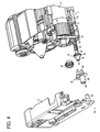
- Fig. 4 is a partial exploded perspective view of a process cartridge 50 according to a second embodiment of the present invention
- Fig. 5 is a partial exploded perspective view of the process cartridge 50 shown in Fig. 4 from which a photosensitive drum 3 is removed.
- a cleaning unit 7 arranged in the process cartridge 50 includes a cleaning blade 70 acting as a cleaning member and a conveying coil spring 71 for conveying toners removed from the photosensitive drum 3 by the cleaning blade 70 out of the process cartridge 50, the cleaning blade 70 is fixed to a side wall 72 of the cleaning unit 7 with a screw 73.
- the rotary supporting member 74 includes a connecting part 75 formed like a split-pin shape inserted to be contacted with an inner periphery of the conveying coil spring 71 and connected to it, a shaft part 76 subsequent to the connecting part 75 to hold the cylindrical seal member not shown, a driving shaft 78 inserted into a shaft hole 77 formed at the side wall 72 of the cleaning unit 7 and rotatably supporting a position setting hole 80, and a gear 79 for transmitting a driving action of the conveying coil spring 71 arranged at the driving shaft 78.
- the rotary supporting member 74 is made such that the position setting hole 80 is formed at the extremity end of the driving shaft 78 and a pin 82 arranged at a holder 81 is fitted into the position setting hole 80.
- the holder 81 is arranged between the rotary supporting member 74 and the outer cover member 51 as described later in detail, and the rotary supporting member 74 is rotatably supported at the holder 81 supported by the outer cover member 51.
- An idler gear 83 for use in transmitting a rotation of the photosensitive drum 3 to the gear 79 is rotatably supported at the holder 81.
- the cleaning unit 7 according to the second embodiment is operated such that the conveying coil spring 71 is driven by the photosensitive drum 3, rotation of the photosensitive drum 3 is transmitted through the idler gear 83 to cause its rotating direction to be the same as that of the photosensitive drum 3.
- Rotating direction of the conveying coil spring 71 is set to be the same direction as that of the photosensitive drum 3 to enable the conveying coil spring 71 to transport the removed toners in an opposite direction to that of the photosensitive drum 3, i.e., while they are being displaced to a side separate from the peripheral surface of the photosensitive drum 3.
- a connecting shaft 84 having its axial center coincided with that of the driving shaft 78 is formed at the holder 81 and the extremity end of the connecting shaft 84, i.e., an end part oppositely facing against the outer cover member 51 of the process cartridge 50 is provided with a fitting hole 85.
- the outer cover member 51 is provided with the pin 52, the pin 52 oppositely faces against the connecting shaft 84 at the extremity end of the holder 81 and the pin 52 is fitted into the fitting hole 85 formed at the connecting shaft 84.
- the process cartridge 50 according to the second embodiment is made such that the rotary supporting member 74 for supporting the conveying coil spring 71 is held indirectly through the holder 81 to hold the conveying coil spring 71 positively and at the same time to enable the conveying coil spring to be rotated in a high precise manner.
- the cleaning unit 7 constituted in this way is operated such that the toners removed from the photosensitive drum 3 by the cleaning blade 70 are temporarily stored in a space having the conveying coil spring 71 arranged therein, and rotation of the conveying coil spring 71 causes the removed toners to be transported in a direction parallel with a longitudinal direction of the cleaning blade 70.
- the conveying coil spring 71 transports the removed toners while they are being displaced to a side spaced apart from the peripheral surface of the photosensitive drum 3. Then, the removed toners are transported out of the process cartridge 50 and stored in a waste toner tank not shown.
- the rotary supporting member 74 and the holder 81 are preferably molded integrally through an injection molding process using polyacetal resin, thereby the number of component parts is substantially reduced. Further, in place of polyacetal resin, the rotary supporting member 74 and the holder 81 may be made of polyamide resin, fluorine resin, polyimide resin, polyamide-imide resin, polyphenyl-sulfide resin, polyethylene resin, polyprene resin and these alloy resins and the like. In addition, as a reinforcing member, either single or more of glass, potassium titanate, talc, mica, lewistonite and natural ores may be added and it is a general process to add these reinforcing members by 5% to 50%.
- reference numeral 53 denotes a side wall of the process cartridge 50 and reference numeral 54 denotes a through hole formed at the side wall 53, and the outer cover member 51 and the side wall 53 in the preferred embodiment are also made of the same materials as those of the aforesaid preferred embodiment.
- the process cartridge 50 constituted in this way also has an advantage that the number of component parts is less as compared with that of the assembling process for holding both sides of the casing under application of an E-shape fixing ring, further a small-sized formation through concentration of the functions of the component parts may also become possible and its assembling process may also become quite easy.
- the toner conveying member is rotatably supported at the predetermined position and at the same time the toner conveying member has a rotary supporting member rotated upon receiving a driving force from outside and the rotary supporting member is rotatably held at the outer cover member by the holding unit, so that the number of component parts is reduced and further a small-sized formation can be realized by concentrating the functions of the component parts and their assembling work can be carried out quite easily.
Landscapes
- Engineering & Computer Science (AREA)
- Computer Vision & Pattern Recognition (AREA)
- Physics & Mathematics (AREA)
- General Physics & Mathematics (AREA)
- Electrophotography Configuration And Component (AREA)
Abstract
Description
- The present invention relates to a process cartridge and an image forming apparatus using the process cartridge.
- In an image forming apparatus such as a copying machine, a printer, a facsimile, and a multifunction product (MFP), a full-color image formation is widely spread. In particular, a tandem-type image forming apparatus having a plurality of image carriers with a highspeed processing is becoming the mainstream of the image forming field. In addition, an apparatus employing a process cartridge including an image carrier and at least one of a charging unit, a developing unit, and a cleaning unit is also known.
- The process cartridge is mounted on the main body of the image forming apparatus in a detachable manner, and can be taken out of the apparatus for its replacing work or maintenance work to avoid a work in a narrow space in the apparatus.
- On the other hand, in a process cartridge including an image carrier and at least a cleaning unit, toners removed by the cleaning unit are conveyed out of the cartridge. In such a process cartridge, it is necessary to arrange a conveying coil spring, a conveying coil, or a conveying screw as a conveying unit for conveying toners in the longitudinal direction of the cleaning member. In this case, because the conveying unit is to be rotated, a gear is provided which engages with a gear of the image carrier.
- In a conventional process cartridge configured as described above, as shown in
Fig. 6 , aphotosensitive drum 101 has a rotating shaft laterally supported between the side walls of the casing of the process cartridge and both axial ends are supported at the side walls of the casing. - Meanwhile, as the cleaning unit, a cleaning blade (not shown) is fixed to the casing of the process cartridge with screws, the toners removed from the
photosensitive drum 101 at the upstream side in the rotating direction of thephotosensitive drum 101 are conveyed out by aconveying coil 102 in the longitudinal direction of the cleaning member and contained in a waste toner tank (not shown). Theconveying coil 102 is inserted and held by ashaft 103 and rotatably supported at the casing through a slidingbearing 104, agear 105 applying a driving force is fixed to theshaft 103 and rotatably held at the casing with anE-shaped fitting ring 106. - However, the conventional process cartridge requires a number of parts, causing a problem of its cost with a bulky size.
- It is an object of the present invention to at least partially solve the problems in the conventional technology.
- According to one aspect of the present invention, there is provided a process cartridge configured to be mounted on a main body of an image forming apparatus in a detachable manner. The process cartridge includes an image carrier on which a toner image is formed; a cleaning unit that cleans the image carrier by removing residual toner remained after transferring the toner image formed on the image carrier onto a transfer medium, which includes a cleaning member that removes the toner from the image carrier and a toner conveying unit that conveys the toner removed by the cleaning member in a longitudinal direction of the cleaning member, including a toner conveying member that makes a rotation to convey the toner removed by the cleaning member in a predetermined direction and a rotary supporting member that supports the toner conveying member at a predetermined position such that the toner conveying member can be rotated and makes a rotation with a driving force from outside; a side wall for supporting the image carrier such that the image carrier can be rotated; and an outer cover member having a surface parallel to the side wall. The side wall includes a through hole. The rotary supporting member includes a holding unit that passes through the through hole and is held at the outer cover member in a rotatable manner.
- Furthermore, according to another aspect of the present invention, there is provided a process cartridge configured to be mounted on a main body of an image forming apparatus in a detachable manner. The process cartridge includes an image carrier on which a toner image is formed; a cleaning unit that cleans the image carrier by removing residual toner remained after transferring the toner image formed on the image carrier onto a transfer medium, which includes a cleaning member that removes the toner from the image carrier and a toner conveying unit that conveys the toner removed by the cleaning member in a longitudinal direction of the cleaning member, including a toner conveying member that makes a rotation to convey the toner removed by the cleaning member in a predetermined direction and a rotary supporting member that supports the toner conveying member at a predetermined position such that the toner conveying member can be rotated and makes a rotation with a driving force from outside; a side wall for supporting the image carrier such that the image carrier can be rotated; an outer cover member having a surface parallel to the side wall; and a holder for supporting the rotary supporting member. The side wall includes a through hole. The holder includes a holding unit that passes through the through hole and is held at the outer cover member in a rotatable manner.
- The above and other objects, features, advantages and technical and industrial significance of the present invention will be better understood by reading the following detailed description of presently preferred embodiments of the invention, when considered in connection with the accompanying drawings.
-
-
Fig. 1 is a schematic diagram of a color printer as an image forming apparatus according to the present invention; -
Fig. 2 is a schematic diagram of a process cartridge in the color printer shown inFig. 1 ; -
Fig. 3 is a partial exploded perspective view of a process cartridge according to a first embodiment of the present invention; -
Fig. 4 is a partial exploded perspective view of a process cartridge according to a second embodiment of the present invention; -
Fig. 5 is a partial exploded perspective view of the process cartridge shown inFig. 4 from which a photosensitive drum is removed; and -
Fig. 6 is a partial exploded perspective view of a conventional process cartridge. - Exemplary embodiments of the present invention will be explained in detail below with reference to the accompanying drawings.
-
Fig. 1 is a schematic diagram of an example of an image forming apparatus 1 that forms a full-color image employing a process cartridge according to the present invention. The image forming apparatus 1 includesimage forming units intermediate transfer belt 10 arranged in opposition to theimage forming units sheet feeding unit 20 for feeding a recording sheet. - The
image forming units image forming unit 2K will be described as a representing one of theimage forming units -
Fig. 2 is a schematic diagram of a process cartridge 50k of the image forming apparatus 1. As shown inFigs .1 and2 , theimage forming unit 2K includes aphotosensitive drum 3K as an image carrier, acharging unit 4K, a developingunit 5K, and acleaning unit 7K arranged in sequence along a rotating direction of thephotosensitive drum 3K. An electrostatic latent image is formed according to image information by a writing light L from awriting unit 8 between thecharging unit 4K and the developingunit 5K. As the image carrier, a belt-like carrier may also be used instead of the drum-like carrier. In the case of the present embodiment, theimage forming unit 2K is made such that thephotosensitive drum 3K, thecharging unit 4K, the developingunit 5K, and thecleaning unit 7K arranged around thephotosensitive drum 3K are constituted as aprocess cartridge 50K stored in a single cartridge. - In the image forming apparatus configured as described above, the
photosensitive drum 3K is rotationally driven by a main motor (not shown), and when it is uniformly charged by thecharging unit 4K, a writing process is executed. - A target image is written according to digital image data from a control unit (not shown) to form an electrostatic latent image under application of the
writing unit 8. The electrostatic latent image formed on thephotosensitive drum 3K is developed by the developingunit 5K. For example, with an application of a DC voltage with an AC bias to a developing sleeve, toners adhere only to image portions of low electric potentials through an irradiation of the writing light, and toners are developed to form a toner image. - The toner image of each of the colors is electrostatically transferred from the photosensitive drum 3k to the
intermediate transfer belt 10 with an application of a bias having a polarity opposite to that of the toners to a primary transfer device constituted as a primary transfer roller 6k oppositely arranged against the photosensitive drums 3k. Then, the toner images of four colors are transferred onto theintermediate transfer belt 10 in a superimposed manner, and collectively transferred onto a recording sheet fed from thesheet feeding unit 20 by asecondary transfer roller 11. - The
sheet feeding unit 20 includes asheet feeding cassette 21. The recording sheet fed from thesheet feeding cassette 21 is conveyed to a secondary transferring device by a pair ofregistration rollers 22 at an appropriate timing at which the toner images are transferred onto theintermediate transfer belt 10. The recording sheet passed through the transferring process is separated from aroller 12 and further conveyed toward afixing unit 13. At thefixing unit 13, the toner images are fixed on the recording sheet when the recording sheet passes through a fixing nip constituted by rollers, and then the recording sheet is discharged to asheet discharging tray 15 throughsheet discharging rollers 14. - The
sheet discharging rollers 14 are used as switch-back conveying members when a duplex image formation is performed. That is, the image forming apparatus 1 is constructed to perform not only a single-sided image formation but also a duplex image formation. Therefore, in the case of the duplex image formation, the recording sheet after fixing the image formed thereon is once conveyed to thesheet discharging tray 15 by thesheet discharging rollers 14, and then thesheet discharging rollers 14 are rotated in the reverse direction with the trailing edge of the recording sheet being held between the rollers. With this arrangement, the recording sheet is conveyed from thesheet discharging tray 15 to a reverse feeding path and fed toward theregistration rollers 22 positioned at a merging part between the reverse feeding path and a feeding path from thesheet feeding cassette 21. A changing-over of the conveying paths for the recording sheet at the time of forming images at the single and the both sides is carried out by a conveying path changing-over claw arranged at the rear side of thefixing unit 13. -
Fig. 3 is a partial exploded perspective view of aprocess cartridge 50 according to a first embodiment of the present invention. As shown inFig. 3 , acleaning unit 7 arranged inside theprocess cartridge 50 includes acleaning blade 70 and aconveying coil spring 71 for conveying toners removed from aphotosensitive drum 3 by thecleaning blade 70 outside theprocess cartridge 50. Thecleaning blade 70 is fixed with ascrew 73 to aside wall 72. - On one end of the
conveying coil spring 71, a rotary supportingmember 74 is provided. The rotary supportingmember 74 includes a connectingpart 75 formed into a split pin shape that is inserted and connected to be contacted with the inner peripheral part of theconveying coil spring 71, ashaft part 76 subsequent to the connectingpart 75 so as to hold a cylindrical seal member (not shown), adriving shaft 78 inserted into ashaft hole 77 formed at theside wall 72 of thecleaning unit 7 and rotatably supporting aposition setting hole 80, and agear 79 for transmitting a driving action of theconveying coil spring 71 arranged at thedriving shaft 78. Further, thegear 79 directly receives a rotary driving force from agear 31 of thephotosensitive drum 3. - The
process cartridge 50 further includes anouter cover member 51, and theouter cover member 51 is provided with apin 52 for use in position setting and supporting therotary supporting member 74. Thepin 52 oppositely faces against the drivingshaft 78 at the extremity end of therotary supporting member 74 and the surface of the drivingshaft 78 opposing against thepin 52 is formed with theposition setting hole 80 into which thepin 52 is rotatably fitted. The holding unit according to the first embodiment is constituted by thepin 52 and theposition setting hole 80, thepin 52 is fitted into theposition setting hole 80 at the time of assembling operation, thereby the conveyingcoil spring 71 can be positively supported and rotated in a high precision. Further, it may also be applicable that the holding unit has a configuration opposite to the aforesaid one, where theouter cover member 51 is provided with theposition setting hole 80 and therotary supporting member 74 is provided with thepin 52 inserted into theposition setting hole 80. - The
cleaning unit 7 constituted as described above is operated such that the toners removed from thephotosensitive drum 3 by thecleaning blade 70 are temporarily stored in a space where the conveyingcoil spring 71 is arranged, and the removed toners are transported in a direction in parallel with a longitudinal direction of thecleaning blade 70 under a rotation of the conveyingcoil spring 71. Then, the toners are transported out of theprocess cartridge 50 and stored in a waste toner tank not shown. Further, as means for conveying toners, either the conveying coil or a conveying screw may be used in place of the conveyingcoil spring 71. - It is preferable that the
rotary supporting member 74 is integrally molded through an injection molding process with polyacetal resin for the connectingpart 75, theshaft part 76, the drivingshaft 78, thegear 79 and theposition setting hole 80 and the number of component parts is substantially reduced. Further, in place of polyacetal resin, therotary supporting member 74 may be made of polyamide resin, fluorine resin, polyimide resin, polyamide-imide resin, polyphenylene sulfide resin, polyethylene resin, polypropylene resin and these alloy resins and the like. Additionally, as a reinforcing member, either single or more of glass, potassium titanate, talc, mica, lewistonite and natural ores may be added and it is a general process to add these reinforcing members by 5% to 50%. - As the cylindrical seal member supported by the
shaft part 76, it is possible to use members made of foamed material, non-woven fabric and woven-fabric and the like. - The
outer cover member 51 has a hole for holding the rotating shaft inserted into thephotosensitive drum 3 and a hole for holding the rotating shaft inserted into the developing unit 5 and an inter-shaft distance between thephotosensitive drum 3 and the developing unit 5 is restricted by both holding holes. Then, therotary supporting member 74 supporting the conveyingcoil spring 71 passes through a throughhole 54 formed at aside wall 53 of theprocess cartridge 50, thepin 52 of theouter cover member 51 is fitted to theposition setting hole 80, thereby assembled into theprocess cartridge 50. - In addition, in view of productivity, the
outer cover member 51 and theside wall 53 of theprocess cartridge 50 are constituted by resin formed through an injection molding, polycarbonate resin, acrylonitrile-butadienestyrene resin, styrene resin, polyphenylene-ether resin, polyphenylene-oxide resin, polyether-terephthalate resin and these alloy resins and the like can be used, and additionally, either single or more of glass, potassium titanate, talc, mica, lewistonite and natural ores may be added to these resins and it is a general process to add these reinforcing members by 5% to 50%. - The
process cartridge 50 constructed in such a way as above can be assembled only by fitting thepin 52 of theouter cover member 51 into theposition setting hole 80 of therotary supporting member 74 supporting the conveyingcoil spring 71. Accordingly, as found in the prior art cartridge shown inFig. 6 , comparing the present invention with the prior art assembling method in which the E-shaped fixing rings are applied to hold the cartridge at both sides of a casing shows that it has a less number of component parts and a small-sized formation can be realized and their assembling operation also becomes quite easy. Further, the conveyingcoil spring 71 is positively supported by therotary supporting member 74 and a removal of thegear 79 and the like is also prevented. -
Fig. 4 is a partial exploded perspective view of aprocess cartridge 50 according to a second embodiment of the present invention; andFig. 5 is a partial exploded perspective view of theprocess cartridge 50 shown inFig. 4 from which aphotosensitive drum 3 is removed. - As shown in
Figs. 4 and5 , acleaning unit 7 arranged in theprocess cartridge 50 includes acleaning blade 70 acting as a cleaning member and a conveyingcoil spring 71 for conveying toners removed from thephotosensitive drum 3 by thecleaning blade 70 out of theprocess cartridge 50, thecleaning blade 70 is fixed to aside wall 72 of thecleaning unit 7 with ascrew 73. - On one end of the conveying
coil spring 71, arotary supporting member 74 is provided. Therotary supporting member 74 includes a connectingpart 75 formed like a split-pin shape inserted to be contacted with an inner periphery of the conveyingcoil spring 71 and connected to it, ashaft part 76 subsequent to the connectingpart 75 to hold the cylindrical seal member not shown, a drivingshaft 78 inserted into ashaft hole 77 formed at theside wall 72 of thecleaning unit 7 and rotatably supporting aposition setting hole 80, and agear 79 for transmitting a driving action of the conveyingcoil spring 71 arranged at the drivingshaft 78. - The
rotary supporting member 74 is made such that theposition setting hole 80 is formed at the extremity end of the drivingshaft 78 and apin 82 arranged at aholder 81 is fitted into theposition setting hole 80. Theholder 81 is arranged between therotary supporting member 74 and theouter cover member 51 as described later in detail, and therotary supporting member 74 is rotatably supported at theholder 81 supported by theouter cover member 51. Anidler gear 83 for use in transmitting a rotation of thephotosensitive drum 3 to thegear 79 is rotatably supported at theholder 81. - Although the
cleaning unit 7 according to the second embodiment is operated such that the conveyingcoil spring 71 is driven by thephotosensitive drum 3, rotation of thephotosensitive drum 3 is transmitted through theidler gear 83 to cause its rotating direction to be the same as that of thephotosensitive drum 3. Rotating direction of the conveyingcoil spring 71 is set to be the same direction as that of thephotosensitive drum 3 to enable the conveyingcoil spring 71 to transport the removed toners in an opposite direction to that of thephotosensitive drum 3, i.e., while they are being displaced to a side separate from the peripheral surface of thephotosensitive drum 3. - A connecting
shaft 84 having its axial center coincided with that of the drivingshaft 78 is formed at theholder 81 and the extremity end of the connectingshaft 84, i.e., an end part oppositely facing against theouter cover member 51 of theprocess cartridge 50 is provided with afitting hole 85. In turn, theouter cover member 51 is provided with thepin 52, thepin 52 oppositely faces against the connectingshaft 84 at the extremity end of theholder 81 and thepin 52 is fitted into thefitting hole 85 formed at the connectingshaft 84. - In this way, the
process cartridge 50 according to the second embodiment is made such that therotary supporting member 74 for supporting the conveyingcoil spring 71 is held indirectly through theholder 81 to hold the conveyingcoil spring 71 positively and at the same time to enable the conveying coil spring to be rotated in a high precise manner. - The
cleaning unit 7 constituted in this way is operated such that the toners removed from thephotosensitive drum 3 by thecleaning blade 70 are temporarily stored in a space having the conveyingcoil spring 71 arranged therein, and rotation of the conveyingcoil spring 71 causes the removed toners to be transported in a direction parallel with a longitudinal direction of thecleaning blade 70. At this time, since the rotating direction of the conveyingcoil spring 71 is the same as that of thephotosensitive drum 3, the conveyingcoil spring 71 transports the removed toners while they are being displaced to a side spaced apart from the peripheral surface of thephotosensitive drum 3. Then, the removed toners are transported out of theprocess cartridge 50 and stored in a waste toner tank not shown. - The
rotary supporting member 74 and theholder 81 are preferably molded integrally through an injection molding process using polyacetal resin, thereby the number of component parts is substantially reduced. Further, in place of polyacetal resin, therotary supporting member 74 and theholder 81 may be made of polyamide resin, fluorine resin, polyimide resin, polyamide-imide resin, polyphenyl-sulfide resin, polyethylene resin, polyprene resin and these alloy resins and the like. In addition, as a reinforcing member, either single or more of glass, potassium titanate, talc, mica, lewistonite and natural ores may be added and it is a general process to add these reinforcing members by 5% to 50%. - In
Figs. 4 and5 ,reference numeral 53 denotes a side wall of theprocess cartridge 50 andreference numeral 54 denotes a through hole formed at theside wall 53, and theouter cover member 51 and theside wall 53 in the preferred embodiment are also made of the same materials as those of the aforesaid preferred embodiment. - The
process cartridge 50 constituted in this way also has an advantage that the number of component parts is less as compared with that of the assembling process for holding both sides of the casing under application of an E-shape fixing ring, further a small-sized formation through concentration of the functions of the component parts may also become possible and its assembling process may also become quite easy. - According to one aspect of the present invention, the toner conveying member is rotatably supported at the predetermined position and at the same time the toner conveying member has a rotary supporting member rotated upon receiving a driving force from outside and the rotary supporting member is rotatably held at the outer cover member by the holding unit, so that the number of component parts is reduced and further a small-sized formation can be realized by concentrating the functions of the component parts and their assembling work can be carried out quite easily.
- Although the invention has been described with respect to specific embodiments for a complete and clear disclosure, the appended claims are not to be thus limited but are to be construed as embodying all modifications and alternative constructions that may occur to one skilled in the art that fairly fall within the basic teaching herein set forth.
Claims (7)
- A process cartridge (50) configured to be mounted on a main body of an image forming apparatus (1) in a detachable manner, the process cartridge (50) comprising:an image carrier (3) on which a toner image is formed;a cleaning unit (7) that cleans the image carrier (3) by removing residual toner remained after transferring the toner image formed on the image carrier (3) onto a transfer medium, the cleaning unit (7) including
a cleaning member (70) that removes the toner from the image carrier (3), and
a toner conveying unit that conveys the toner removed by the cleaning member (70) in a longitudinal direction of the cleaning member (70), the toner conveying unit including
a toner conveying member (71) that makes a rotation to convey the toner removed by the cleaning member (70) in a predetermined direction, and
a rotary supporting member (74) that supports the toner conveying member (71) at a predetermined position such that the toner conveying member (71) can be rotated and makes a rotation with a driving force from outside;a side wall (53) for supporting the image carrier (3) such that the image carrier (3) can be rotated; andan outer cover member (51) having a surface parallel to the side wall (53), whereinthe side wall (53) includes a through hole (54), andthe rotary supporting member (74) includes a holding unit (52, 80) that passes through the through hole (54) and is held at the outer cover member (51) in a rotatable manner. - A process cartridge (50) according to claim 1, wherein
the holding unit (52, 80) includes a convex part fitted to one of the rotary supporting member (74) and the outer cover member (51) and a concave part to which the convex part is fitted at the other of the rotary supporting member (74) and the outer cover member (51). - A process cartridge (50) according to claim 1 or 2, wherein
the rotary supporting member (74) is constituted by supporting parts for supporting the toner conveying member (71), a gear (79) for rotationally driving the toner conveying member (71), and one of the holding unit (52, 80) is integrally formed with resin through an injection molding process. - A process cartridge (50) according to claim 3, wherein
the resin is any one of polyscetal resin, polyamide resin, fluorine resin, polyimide resin, polyamide-imide resin, polyphenylene-sulfide resin, polyethylene resin, polyprene resin, and an alloy resin of above resins. - A process cartridge (50) configured to be mounted on a main body of an image forming apparatus (1) in a detachable manner, the process cartridge (50) comprising:an image carrier (3) on which a toner image is formed;a cleaning unit (7) that cleans the image carrier (3) by removing residual toner remained after transferring the toner image formed on the image carrier (3) onto a transfer medium, the cleaning unit (7) including
a cleaning member (70) that removes the toner from the image carrier (3), and
a toner conveying unit that conveys the toner removed by the cleaning member (70) in a longitudinal direction of the cleaning member (70), the toner conveying unit including
a toner conveying member (71) that makes a rotation to convey the toner removed by the cleaning member (70) in a predetermined direction, and
a rotary supporting member (74) that supports the toner conveying member (71) at a predetermined position such that the toner conveying member (71) can be rotated and makes a rotation with a driving force from outside;a side wall (53) for supporting the image carrier (3) such that the image carrier (3) can be rotated;an outer cover member (51) having a surface parallel to the side wall (53); anda holder (81) for supporting the rotary supporting member (74), whereinthe side wall (53) includes a through hole (54), andthe holder (81) includes a holding unit (52, 80) that passes through the through hole (54) and is held at the outer cover member (51) in a rotatable manner. - A process cartridge (50) according to claim 5, wherein
the rotary supporting member (74) includes a gear (79) for rotationally driving the toner conveying member (71), the gear (79) is drivingly connected to a gear (31) arranged at the image carrier (3) through an idler gear (83) arranged at the holder (81). - An image forming apparatus comprising:a process cartridge (50) according to any one of claims 1 to 6.
Applications Claiming Priority (1)
| Application Number | Priority Date | Filing Date | Title |
|---|---|---|---|
| JP2007330209A JP5130035B2 (en) | 2007-12-21 | 2007-12-21 | Process cartridge and image forming apparatus |
Publications (2)
| Publication Number | Publication Date |
|---|---|
| EP2073073A1 true EP2073073A1 (en) | 2009-06-24 |
| EP2073073B1 EP2073073B1 (en) | 2018-03-07 |
Family
ID=40445365
Family Applications (1)
| Application Number | Title | Priority Date | Filing Date |
|---|---|---|---|
| EP08254003.0A Expired - Fee Related EP2073073B1 (en) | 2007-12-21 | 2008-12-15 | Process cartridge and image forming apparatus |
Country Status (2)
| Country | Link |
|---|---|
| EP (1) | EP2073073B1 (en) |
| JP (1) | JP5130035B2 (en) |
Citations (5)
| Publication number | Priority date | Publication date | Assignee | Title |
|---|---|---|---|---|
| EP0827049A2 (en) * | 1996-08-29 | 1998-03-04 | Canon Kabushiki Kaisha | Process cartridge, electrophotographic image forming apparatus and electro- photographic image forming apparatus transmissions method |
| US20010026707A1 (en) * | 2000-01-19 | 2001-10-04 | Shigeo Miyabe | Process cartridge, engaging member therefor and method for mounting developing roller and magnet |
| JP2004117696A (en) * | 2002-09-25 | 2004-04-15 | Canon Inc | Bearing member, process cartridge and image forming apparatus |
| US20050238384A1 (en) * | 2004-04-26 | 2005-10-27 | Atsushi Sampe | Image forming apparatus |
| JP2007133045A (en) * | 2005-11-08 | 2007-05-31 | Ricoh Co Ltd | Cap member and imaging unit |
Family Cites Families (3)
| Publication number | Priority date | Publication date | Assignee | Title |
|---|---|---|---|---|
| JP3061302B2 (en) * | 1991-07-26 | 2000-07-10 | 株式会社リコー | Toner transport device |
| JPH08137156A (en) * | 1994-11-10 | 1996-05-31 | Canon Inc | Process cartridge and image forming device |
| JP3803164B2 (en) * | 1997-03-27 | 2006-08-02 | 株式会社リコー | Residual toner collecting device of image forming apparatus, image forming device |
-
2007
- 2007-12-21 JP JP2007330209A patent/JP5130035B2/en not_active Expired - Fee Related
-
2008
- 2008-12-15 EP EP08254003.0A patent/EP2073073B1/en not_active Expired - Fee Related
Patent Citations (5)
| Publication number | Priority date | Publication date | Assignee | Title |
|---|---|---|---|---|
| EP0827049A2 (en) * | 1996-08-29 | 1998-03-04 | Canon Kabushiki Kaisha | Process cartridge, electrophotographic image forming apparatus and electro- photographic image forming apparatus transmissions method |
| US20010026707A1 (en) * | 2000-01-19 | 2001-10-04 | Shigeo Miyabe | Process cartridge, engaging member therefor and method for mounting developing roller and magnet |
| JP2004117696A (en) * | 2002-09-25 | 2004-04-15 | Canon Inc | Bearing member, process cartridge and image forming apparatus |
| US20050238384A1 (en) * | 2004-04-26 | 2005-10-27 | Atsushi Sampe | Image forming apparatus |
| JP2007133045A (en) * | 2005-11-08 | 2007-05-31 | Ricoh Co Ltd | Cap member and imaging unit |
Also Published As
| Publication number | Publication date |
|---|---|
| JP5130035B2 (en) | 2013-01-30 |
| EP2073073B1 (en) | 2018-03-07 |
| JP2009151177A (en) | 2009-07-09 |
Similar Documents
| Publication | Publication Date | Title |
|---|---|---|
| US7424263B2 (en) | Toner recovery belt conveyor, process cartridge, and image forming apparatus using the same | |
| JP4798786B2 (en) | Belt device and image forming apparatus | |
| JP4047085B2 (en) | Belt traveling device and image forming apparatus | |
| JP4965104B2 (en) | Image forming apparatus | |
| JP2010281943A (en) | Image forming apparatus | |
| US10613451B2 (en) | Image forming apparatus with moveable transfer members | |
| JP4698255B2 (en) | Image forming apparatus | |
| US10747171B2 (en) | Image forming apparatus with a waste container positioned on a side opposite electrical contacts and rotational drive receiving portions | |
| JP2006126709A (en) | Image forming apparatus and process cartridge | |
| US9785089B2 (en) | Toner case and image forming apparatus including the same | |
| JP2003122228A (en) | Image forming device | |
| EP2073073B1 (en) | Process cartridge and image forming apparatus | |
| JP2008058486A (en) | Image forming apparatus | |
| JP4372186B2 (en) | Photoconductor drive mechanism | |
| JP2001249508A (en) | Image forming unit and image forming device | |
| US8761632B2 (en) | Image forming apparatus and rotary developing device | |
| JP4628727B2 (en) | Process cartridge and image forming apparatus | |
| JP2009116138A (en) | Toner recovery device and image forming apparatus | |
| JP5483017B2 (en) | Belt device and image forming apparatus | |
| JP5376196B2 (en) | Powder conveying apparatus and image forming apparatus | |
| JP7333013B2 (en) | Storage container and image forming apparatus | |
| JP2004045960A (en) | Color image forming apparatus | |
| JP4897444B2 (en) | Cleaning device and image forming apparatus having the same | |
| JP2008020820A (en) | Process cartridge and image forming apparatus | |
| CN107239020B (en) | Developer conveying device and image forming apparatus |
Legal Events
| Date | Code | Title | Description |
|---|---|---|---|
| PUAI | Public reference made under article 153(3) epc to a published international application that has entered the european phase |
Free format text: ORIGINAL CODE: 0009012 |
|
| 17P | Request for examination filed |
Effective date: 20081219 |
|
| AK | Designated contracting states |
Kind code of ref document: A1 Designated state(s): AT BE BG CH CY CZ DE DK EE ES FI FR GB GR HR HU IE IS IT LI LT LU LV MC MT NL NO PL PT RO SE SI SK TR |
|
| AX | Request for extension of the european patent |
Extension state: AL BA MK RS |
|
| AKX | Designation fees paid |
Designated state(s): DE FR GB |
|
| 17Q | First examination report despatched |
Effective date: 20120614 |
|
| GRAP | Despatch of communication of intention to grant a patent |
Free format text: ORIGINAL CODE: EPIDOSNIGR1 |
|
| INTG | Intention to grant announced |
Effective date: 20170913 |
|
| GRAS | Grant fee paid |
Free format text: ORIGINAL CODE: EPIDOSNIGR3 |
|
| GRAA | (expected) grant |
Free format text: ORIGINAL CODE: 0009210 |
|
| AK | Designated contracting states |
Kind code of ref document: B1 Designated state(s): DE FR GB |
|
| REG | Reference to a national code |
Ref country code: GB Ref legal event code: FG4D |
|
| REG | Reference to a national code |
Ref country code: DE Ref legal event code: R096 Ref document number: 602008054308 Country of ref document: DE |
|
| REG | Reference to a national code |
Ref country code: DE Ref legal event code: R097 Ref document number: 602008054308 Country of ref document: DE |
|
| PLBE | No opposition filed within time limit |
Free format text: ORIGINAL CODE: 0009261 |
|
| STAA | Information on the status of an ep patent application or granted ep patent |
Free format text: STATUS: NO OPPOSITION FILED WITHIN TIME LIMIT |
|
| 26N | No opposition filed |
Effective date: 20181210 |
|
| PGFP | Annual fee paid to national office [announced via postgrant information from national office to epo] |
Ref country code: DE Payment date: 20211210 Year of fee payment: 14 Ref country code: GB Payment date: 20211221 Year of fee payment: 14 Ref country code: FR Payment date: 20211224 Year of fee payment: 14 |
|
| REG | Reference to a national code |
Ref country code: DE Ref legal event code: R119 Ref document number: 602008054308 Country of ref document: DE |
|
| GBPC | Gb: european patent ceased through non-payment of renewal fee |
Effective date: 20221215 |
|
| PG25 | Lapsed in a contracting state [announced via postgrant information from national office to epo] |
Ref country code: GB Free format text: LAPSE BECAUSE OF NON-PAYMENT OF DUE FEES Effective date: 20221215 Ref country code: DE Free format text: LAPSE BECAUSE OF NON-PAYMENT OF DUE FEES Effective date: 20230701 |
|
| PG25 | Lapsed in a contracting state [announced via postgrant information from national office to epo] |
Ref country code: FR Free format text: LAPSE BECAUSE OF NON-PAYMENT OF DUE FEES Effective date: 20221231 |