EP2072999A1 - Method of identifying abnormality and analysis apparatus - Google Patents
Method of identifying abnormality and analysis apparatus Download PDFInfo
- Publication number
- EP2072999A1 EP2072999A1 EP07791693A EP07791693A EP2072999A1 EP 2072999 A1 EP2072999 A1 EP 2072999A1 EP 07791693 A EP07791693 A EP 07791693A EP 07791693 A EP07791693 A EP 07791693A EP 2072999 A1 EP2072999 A1 EP 2072999A1
- Authority
- EP
- European Patent Office
- Prior art keywords
- abnormality
- removal
- reagent
- measurement
- concentration
- Prior art date
- Legal status (The legal status is an assumption and is not a legal conclusion. Google has not performed a legal analysis and makes no representation as to the accuracy of the status listed.)
- Withdrawn
Links
- 238000000034 method Methods 0.000 title claims abstract description 572
- 238000004458 analytical method Methods 0.000 title claims abstract description 97
- 230000005856 abnormality Effects 0.000 title claims abstract description 46
- 239000003153 chemical reaction reagent Substances 0.000 claims abstract description 309
- 238000005259 measurement Methods 0.000 claims abstract description 309
- 230000003287 optical effect Effects 0.000 claims abstract description 7
- 238000004140 cleaning Methods 0.000 claims description 161
- 239000000758 substrate Substances 0.000 claims description 67
- 230000007547 defect Effects 0.000 claims description 55
- 238000006243 chemical reaction Methods 0.000 claims description 48
- 239000000126 substance Substances 0.000 claims description 48
- 238000002347 injection Methods 0.000 claims description 30
- 239000007924 injection Substances 0.000 claims description 30
- 239000007788 liquid Substances 0.000 claims description 29
- 239000000427 antigen Substances 0.000 description 82
- 102000036639 antigens Human genes 0.000 description 82
- 108091007433 antigens Proteins 0.000 description 82
- 238000012546 transfer Methods 0.000 description 65
- 239000006249 magnetic particle Substances 0.000 description 49
- 239000000523 sample Substances 0.000 description 29
- 238000006911 enzymatic reaction Methods 0.000 description 22
- 238000010586 diagram Methods 0.000 description 20
- 239000000243 solution Substances 0.000 description 14
- 230000008105 immune reaction Effects 0.000 description 12
- 238000005375 photometry Methods 0.000 description 11
- 238000004886 process control Methods 0.000 description 11
- 230000035484 reaction time Effects 0.000 description 10
- 238000012360 testing method Methods 0.000 description 9
- 239000000969 carrier Substances 0.000 description 7
- 230000001900 immune effect Effects 0.000 description 7
- 239000007853 buffer solution Substances 0.000 description 6
- 238000000926 separation method Methods 0.000 description 6
- 239000012535 impurity Substances 0.000 description 5
- 238000003756 stirring Methods 0.000 description 5
- 102000004190 Enzymes Human genes 0.000 description 4
- 108090000790 Enzymes Proteins 0.000 description 4
- 230000006870 function Effects 0.000 description 4
- 239000008280 blood Substances 0.000 description 3
- 210000004369 blood Anatomy 0.000 description 3
- 238000007865 diluting Methods 0.000 description 3
- 238000005516 engineering process Methods 0.000 description 3
- 0 CC=CC=C(CC*)C=CC=CCCCN=O Chemical compound CC=CC=C(CC*)C=CC=CCCCN=O 0.000 description 2
- 238000010876 biochemical test Methods 0.000 description 2
- 239000012295 chemical reaction liquid Substances 0.000 description 2
- 238000004891 communication Methods 0.000 description 2
- 239000007790 solid phase Substances 0.000 description 2
- 210000002700 urine Anatomy 0.000 description 2
- MXTLFHNDDSPBDP-GAJQIJDCSA-N C=C(C(CCN=O)/C=C1)/C=C\C=C/C1=C Chemical compound C=C(C(CCN=O)/C=C1)/C=C\C=C/C1=C MXTLFHNDDSPBDP-GAJQIJDCSA-N 0.000 description 1
- 208000035473 Communicable disease Diseases 0.000 description 1
- 238000002835 absorbance Methods 0.000 description 1
- 230000005540 biological transmission Effects 0.000 description 1
- 238000004737 colorimetric analysis Methods 0.000 description 1
- 238000007796 conventional method Methods 0.000 description 1
- 230000002950 deficient Effects 0.000 description 1
- 238000010790 dilution Methods 0.000 description 1
- 239000012895 dilution Substances 0.000 description 1
- 238000001035 drying Methods 0.000 description 1
- 230000000694 effects Effects 0.000 description 1
- 239000012530 fluid Substances 0.000 description 1
- 238000010348 incorporation Methods 0.000 description 1
- 238000004020 luminiscence type Methods 0.000 description 1
- 230000005389 magnetism Effects 0.000 description 1
- 230000003595 spectral effect Effects 0.000 description 1
Images









Classifications
-
- G—PHYSICS
- G01—MEASURING; TESTING
- G01N—INVESTIGATING OR ANALYSING MATERIALS BY DETERMINING THEIR CHEMICAL OR PHYSICAL PROPERTIES
- G01N35/00—Automatic analysis not limited to methods or materials provided for in any single one of groups G01N1/00 - G01N33/00; Handling materials therefor
- G01N35/00584—Control arrangements for automatic analysers
- G01N35/00594—Quality control, including calibration or testing of components of the analyser
- G01N35/00613—Quality control
- G01N35/00623—Quality control of instruments
-
- G—PHYSICS
- G01—MEASURING; TESTING
- G01N—INVESTIGATING OR ANALYSING MATERIALS BY DETERMINING THEIR CHEMICAL OR PHYSICAL PROPERTIES
- G01N35/00—Automatic analysis not limited to methods or materials provided for in any single one of groups G01N1/00 - G01N33/00; Handling materials therefor
- G01N35/10—Devices for transferring samples or any liquids to, in, or from, the analysis apparatus, e.g. suction devices, injection devices
- G01N35/1004—Cleaning sample transfer devices
Definitions
- the present invention relates to identification of an abnormality in an analyzer which analyzes a specimen based on optical measurement.
- An analyzer can analyze a number of specimens at the same time, and further, can analyze many components immediately and accurately.
- the analyzer is used for various tests such as an immunological test, a biochemical test, and a blood-transfusion test.
- the analyzer which performs the immunological test includes a reaction system in which the specimen is reacted with a reagent in a reaction vessel, a removal system in which unreacted substances are removed out of the reaction vessel, and a photometry system in which the amount of light emission from an immune complex obtained through reaction between the specimen and each reagent is measured. These systems are arranged on plural turntables, respectively.
- the analyzer further includes plural dispense/transfer systems which dispense or transfer the specimen, the reagent, or a reaction liquid into each of the systems.
- the analyzer performs immunological tests for various contents of the analysis (e.g., see Patent Document 1).
- Patent Document 1 Japanese Patent Application Laid-open No. 2003-83988
- the abnormality of the analyzer has been examined as follows.
- the analyzer performs a series of analysis processes, which are to be performed on an actual specimen, on a reference specimen with which a known analysis result should be produced, and then it is checked whether the analysis result produced by the analyzer is consistent with the known result.
- an operator of the analyzer determines that the analyzer functions normally whereas when the analysis result obtained from the actual analysis of the reference specimen is inconsistent with the known analysis result, the operator determines that the analyzer functions abnormally.
- the operator can determine that there is an abnormality in the analyzer, but can hardly know which process or system of the analyzer exactly causes the abnormality. Especially, it is difficult to properly identify the abnormality in the analyzer which performs the immunological test, since the analyzer of the kind has a complex configuration in which various factors such as reaction time, a reagent to be used, a system to be used, and a timing to use the system are different depending on the contents of the analysis processes.
- dispense accuracy of the dispense/transfer system is examined by dispensing the reagent which has predetermined absorbance characteristics into the reaction vessel, and referring to a measurement result obtained through a colorimetric method.
- the analyzer which performs the immunological test does not include a colorimetric measurement unit. Therefore, to examine the dispense accuracy, the operator needs to perform the colorimetric measurement using a spectral photometer which is not included in the analyzer.
- the present invention is made in view of the above problems of the conventional technology, and an object of the present invention is to provide an abnormality-identifying method, an analyzer, and a reagent which can identify an abnormality of an analyzer properly and easily.
- an abnormality-identifying method identifies an abnormality in an analyzer which analyzes a specimen based on optical measurement.
- the method includes a reference-acquisition measurement process step that acquires a reference value which is a measurement result obtained by using a low-concentration reagent containing a component in predetermined very low concentrations, an abnormality-identification measurement process step that acquires an abnormality-identification measurement value which is a measurement result obtained through an analysis process using a high-concentration reagent containing the component in predetermined high concentrations, and an abnormality identifying step that identifies an abnormality in an analysis process concerning removal of the high-concentration reagent based on whether the abnormality-identification measurement value is within an acceptable range set based on the reference value.
- the reference-acquisition measurement process step may include a first measurement step that measures a light-emission amount as the reference value after an analysis process which allows the component to emit light.
- the abnormality-identification measurement process step may includes a removal step that, after injecting the high-concentration reagent into a reaction vessel, removes the component in the high-concentration reagent in the reaction vessel by performing a same process as a removal process for removing unreacted substance in the reaction vessel, among analysis processes performed on the specimen, and a second measurement step that measures a light-emission amount as the abnormality-identification measurement value after an analysis process which allows the component to emit light.
- the abnormality identifying step may identify a removal defect in the removal process among the analysis processes performed on the specimen when the abnormality-identification measurement value is not within the acceptable range.
- the removal process may include a first removal process and a second removal process
- the removal step may be one of a first removal step which performs a same process as the first removal process, a second removal step which performs a same process as the second removal process, and a third removal step which performs a same process as the first removal process and a same process as the second removal process.
- the abnormality-identification measurement process step may identify a removal defect in the first removal process among the analysis processes performed on the specimen, when the removal step is the first removal step and the abnormality-identification measurement value is not within the acceptable range, a removal defect in the second removal process among the analysis processes performed on the specimen, when the removal step is the second removal step and the abnormality-identification measurement value is not within the acceptable range, and a removal defect in at least one of the first removal process and the second removal process, when the removal step is the third removal step and the abnormality-identification measurement value is not within the acceptable range.
- the reference-acquisition measurement process step may include a first measurement step that measures a light-emission amount as the reference value after an analysis process to allow the component emit light.
- the abnormality-identification measurement process step may include a high-concentration-reagent injection step that injects the high-concentration reagent into a reaction vessel using a liquid injection system which injects liquid into the reaction vessel, a zero-concentration-reagent injection step that, after the high-concentration-reagent injection step, injects a zero-concentration reagent containing none of the component in a reaction vessel which is different from the reaction vessel in which the high-concentration reagent is injected using the liquid injection system which is cleaned, and a second measurement step that measures a light-emission amount as the abnormality-identification measurement value of the reaction vessel into which the zero-concentration reagent is injected after an analysis process to allow the component to emit light.
- the abnormality identifying step may identify a defect in a cleaning process of the liquid injection
- the component may be a labeled substance which is bound to a light-emitting substrate.
- an analyzer analyzes a specimen based on optical measurement.
- the analyzer includes a measurement unit that acquires a reference value which is a measurement result obtained by using a low-concentration reagent containing a component in predetermined very low concentrations, and acquires an abnormality-identification measurement value which is a measurement result obtained through analysis process using a high-concentration reagent containing the component in predetermined high concentrations; and an identifying unit that identifies an abnormality in an analysis process concerning removal of the high-concentration reagent based on whether the abnormality-identification measurement value is within an acceptable range set based on the reference value.
- the analyzer according to the present invention may further include a removing unit that performs a removal process among analysis processes performed on the specimen to remove unreacted substance from a reaction vessel.
- the removing unit may remove, after the high-concentration reagent is injected into the reaction vessel, a component of the high-concentration reagent in the reaction vessel by performing a same process as the removal process.
- the measurement unit may measure a light-emission amount as the reference value after an analysis process which allows the component in the low-concentration reagent to emit light, and measures a light-emission amount as the abnormality-identification measurement value after the removing unit removes the component of the high-concentration reagent and an analysis process is performed to allow the component to emit light.
- the identifying unit may identify a removal defect in the removal process among the analysis processes performed on the specimen when the abnormality-identification measurement value is not within the acceptable range.
- the removal process may include a first removal process and a second removal process
- the removing unit may perform at least one of a same process as the first removal process and a same process as the second removal process, to remove the component of the high-concentration reagent in the reaction vessel.
- the identifying unit may identify: a removal defect in the first removal process among the analysis processes performed on the specimen, when the removing unit performs the same process as the first removal process and the abnormality-identification measurement value is not within the acceptable range; a removal defect in the second removal process among the analysis processes performed on the specimen, when the removing unit performs the same process as the second removal process and the abnormality-identification measurement value is not within the acceptable range; and a removal defect in one or both of the first removal process and the second removal process among the analysis processes performed on the specimen, when the removing unit performs the same process as the first removal process and the same process as the second removal process and the abnormality-identification measurement value is not within the acceptable range.
- the analyzer may further include a liquid injecting unit that injects liquid into the reaction vessel.
- the liquid injecting unit may inject the high-concentration reagent into the reaction vessel, may be cleaned after the high-concentration-reagent injection, and may subsequently inject a zero-concentration reagent, which contains none of the component, into a different reaction vessel from the reaction vessel into which the high-concentration reagent is injected.
- the measurement unit may measure a light-emission amount after an analysis process to allow the component in the low-concentration reagent to emit light as the reference value, and measures a light-emission amount from the reaction vessel into which the zero-concentration reagent is injected as the abnormality-identification measurement value, after an analysis process to allow the component to emit light.
- the identifying unit may identify a defect in a cleaning process performed by the liquid injecting unit among the analysis processes performed on the specimen, when the abnormality-identification measurement value is not within the acceptable range.
- the component may be a labeled substance which is bound to a light-emitting substrate.
- a measurement result is obtained as a reference value using a low-concentration reagent containing a component in predetermined very low concentrations
- a measurement result is obtained as an abnormality-identification measurement value using a high-concentration reagent containing the component in predetermined high concentrations through an analysis process.
- An abnormality in the analysis process concerning removal of the high-concentration reagent is identified based on whether the abnormality-identification measurement value is within an acceptable range set based on the reference value. Therefore, the abnormality in the analyzer can be identified correctly and easily.
- a BF cleaning process is one of analysis processes performed on a specimen, and serves to remove unreacted substances in a reaction vessel. Described below is a case where presence/absence of defect in unreacted-substance removal in the BF cleaning process is identified.
- a reference value is set to a light-emission amount obtained from a low-concentration reagent containing antigens in very low concentrations.
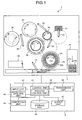
- analyzer 1 is a schematic diagram of a configuration of the analyzer according to the present embodiment.
- analyzer 1 includes a measurement system 2 which measures light emission from a reaction between a specimen and a reagent, a control system 4 which controls the analyzer 1 as a whole including the measurement system 2 and analyzes a measurement result of the measurement system 2.
- the analyzer 1 automatically performs an immunological analysis on plural specimens through cooperation of these two systems.
- the measurement system 2 includes a specimen transfer unit 21, a chip holder 22, a specimen dispense/transfer system 23, an immune reaction table 24, a BF table 25, a first-reagent holder 26, a second-reagent holder 27, a first-reagent dispense/transfer system 28, a second-reagent dispense/transfer system 29, an enzyme reaction table 30, a photometry system 31, a first-cuvette transfer system 32, and a second-cuvette transfer system 33.
- Each component of the measurement system 2 includes one or more units which perform a predetermined operation.
- the control system 4 includes a control unit 41, an input unit 43, an analysis unit 44, an identifying unit 45, a storage unit 46, an output unit 47, and a transceiving unit 48. Each component of the measurement system 2 and the control system 4 is electrically connected with the control unit 41.
- the measurement system 2 is described.
- the specimen transfer unit 21 holds plural specimen vessels 21a which contain specimens, and plural specimen racks 21b which are to be transferred sequentially in a direction along an arrow in the figure.
- the specimens contained in the specimen vessels 21a are blood, urine, or the like extracted from a donor who provides the specimens.
- the chip holder 22 has a chip case in which plural chips are arranged, and the chip is provided out of the case.
- the chip is a disposal sample chip which is exchanged for each dispensing of the specimen.
- the chip is mounted on a distal end of a nozzle of the specimen dispense/transfer system 23 so that carryover in measurement of infectious diseases is prevented.
- the specimen dispense/transfer system 23 includes an arm which can be moved up and down in vertical directions and rotated around a central axis, i.e., a vertical line crossing a proximal end thereof.
- a probe for sucking and dispensing the specimen is attached to a distal end of the arm.
- the specimen dispense/transfer system 23 makes the probe suck the specimen out of the specimen vessel 21a which has been transferred to a predetermined position by the specimen transfer unit 21, rotates the arm to dispense the specimen into a cuvette which has been transferred to a predetermined position by the BF table 25, and thus transfers the specimen into the cuvette on the BF table 25 at a predetermined timing.
- the immune reaction table 24 includes reaction lines where the specimen is reacted with a predetermined reagent corresponding to an analysis point in each of the arranged cuvettes.
- the immune reaction table 24 can be rotated around a rotation axis, i.e., a vertical line crossing a center of the immune reaction table 24 for each of the reaction lines, and thus the cuvette arranged on the immune reaction table 24 is transferred to a predetermined position at a predetermined timing. As shown in FIG.
- the immune reaction table 24 may form three reaction lines consisting of an outer circular line 24a for pretreatment and pre-dilution, a middle circular line 24b for the immune reaction of the specimen and a solid-phase carrier reagent, and an inner circular line 24c for the immune reaction of the specimen and a reference specimen.
- the BF table 25 performs a BF cleaning process by which a predetermined cleaning fluid is discharged and sucked out to perform the BF (bound-free) separation, i.e., to separate unreacted substances of the specimen or the reagent.
- the BF table 25 can be rotated around a rotation axis, i.e., a vertical line crossing a center of the BF table 25 for each of the reaction lines, and thus the cuvette arranged on the BF table 25 is transferred to the predetermined position at the predetermined timing.
- the BF table 25 includes a magnetic collection system which magnetically collects the magnetic-particle carriers used for the BF separation, a BF cleaning nozzle which performs the BF separation, and a stir system which mixes up the carriers magnetically collected.
- the BF cleaning process performed by the BF table 25 includes a first BF cleaning process and a second BF cleaning process. The first BF cleaning process and the second BF cleaning process may employ different BF cleaning nozzle and magnetic collection system.
- the first-reagent holder 26 can hold plural reagent vessels which contain the first reagent to be dispensed into the cuvette which is set on the BF table 25.
- the second-reagent holder 27 can hold plural reagent vessels which contain the second reagent to be dispensed into the cuvette which is set on the BF table 25.
- Both the first-reagent holder 26 and the second-reagent holder 27 can be rotated in a clockwise and counterclockwise direction by a driving system (not shown) to transfer a desired reagent vessel to a reagent sucking position of the first-reagent dispense/transfer system 28 and the second-reagent dispense/transfer system 29.
- the first-reagent dispense/transfer system 28 includes an arm which can be moved up and down in vertical directions and rotated around a central axis, i.e., a vertical line crossing a proximal end thereof.
- a probe for sucking and dispensing the first reagent is attached to a distal end of the arm.
- the first-reagent dispense/transfer system 28 makes the probe suck the reagent out of the reagent vessel which has been transferred to a predetermined position by the first-reagent holder 26, and rotates the arm to dispense the reagent into a cuvette which has been transferred to a predetermined position by the BF table 25.
- a portion of the first-reagent dispense/transfer system 28 brought into contact with the reagent is cleaned every time the first-reagent dispense/transfer system 28 finishes dispensing the reagent.
- the second-reagent dispense/transfer system 29 is configured similarly to the first-reagent dispense/transfer system 28.
- the second-reagent dispense/transfer system 29 makes the probe suck the reagent out of the reagent vessel which has been transferred to a predetermined position by the second-reagent holder 27, and rotates the arm to dispense the reagent into the cuvette which has been transferred to a predetermined position by the BF table 25.
- a portion of the second-reagent dispense/transfer system 29 brought into contact with the reagent is cleaned every time the second-reagent dispense/transfer system 29 finishes dispensing the reagent.
- the enzyme reaction table 30 is the reaction line in which an enzyme reaction which involves light emission is caused in a cuvette into which the substrate solution has been dispensed.
- the photometry system 31 measures the light emission from the reaction liquid in the cuvette.
- the photometry system 31 includes, for example, a photoelectron multiplier tube which detects a faint light emission from chemical luminescence. Further, the photometry system 31 holds an optical filter to lessen intensity of light depending on the intensity of light emission so that the intensity of light emission can be calculated correctly.
- the first-cuvette transfer system 32 includes an arm which can be moved up and down in the vertical directions, and rotated around the central axis, i.e., the vertical line crossing the proximal end thereof.
- the arm transfers the cuvette containing a liquid to the predetermined positions of the immune reaction table 24, the BF table 25, the enzyme reaction table 30, and a cuvette supplying unit (not shown) and a cuvette disposal unit (not shown) at predetermined timing.
- the second-cuvette transfer system 33 includes an arm which can be moved up and down in the vertical directions, and rotated around the central axis, i.e., the vertical line crossing the proximal end thereof.
- the arm transfers the cuvette containing the liquid to the predetermined positions of the enzyme reaction table 30, the photometry system 31, and the cuvette disposal unit (not shown) at predetermined timing.
- the control system 4 is described.
- the control system 4 is realized by one or more computer systems, and connected with the measurement system 2.
- the control system 4 controls the operation processes of the measurement system 2, and analyzes the measurement result of the measurement system 2 by using various programs related to the processes of the analyzer 1.
- the control unit 41 includes a CPU and the like which provide a control function, and controls the processes and the operations of the components of the analyzer 1.
- the control unit 41 performs a predetermined input/output control on information which is input/output to/from each of the components, and performs a predetermined information process on the information.
- the control unit 41 controls the analyzer 1 by reading out programs from a memory in the storage unit 46.
- the control unit 41 includes a process control unit 42.
- the analyzer 1 acquires the light-emission amount of a low-concentration reagent containing antigens in very low concentrations, as a reference value. Further, the analyzer 1 acquires the light-emission amount of a high-concentration reagent containing antigens in high concentrations after the BF cleaning, as an abnormality-identification measurement value. Based on these values, the analyzer 1 identifies a fault in unreacted-substance removal in the BF cleaning process.
- the process control unit 42 controls each of the systems included in the measurement system 2 to acquire the reference value and the abnormality-measurement value for identifying the abnormality of the analyzer 1.
- the input unit 43 is realized by a keyboard for inputting various information, a mouse for specifying an arbitrary position on a display screen of a display included in the output unit 47, and the like.
- the input unit 43 obtains various types of information for the analysis of the specimen, and instruction information and the like of the analysis operation from an outside.
- the analysis unit 44 performs an analysis process and the like on the specimen based on the measurement result obtained from the measurement system 2.
- the identifying unit 45 determines whether there is an unreacted-substance removal defect in the BF cleaning process among the analysis processes performed on the specimen.
- the BF cleaning process serves to remove unreacted substances in the reaction vessel.
- the identifying unit 45 sets a reference value to the light-emission amount of the low-concentration reagent containing antigens in very low concentrations, and determines whether there is an unreacted-substance removal defect in the BF cleaning process or not based on the determination on whether the abnormality-identification measurement value, which is the light-emission amount of the high-concentration reagent containing antigens in high concentrations after the BF cleaning, is within an acceptable range, which is set based on the reference value.
- the storage unit 46 includes a hard disk, which magnetically stores information therein, and a memory, which loads various programs related to a process of the analyzer 1 from the hard disk and electrically stores the programs therein when the analyzer 1 performs the process. Thus, the storage unit 46 stores various types of information including the analysis result and the like of the specimen.
- the storage unit 46 may include a sub-storage apparatus which can read out information stored in a storage medium such as a CD-ROM, a DVD-ROM, and a PC card.
- the output unit 47 includes a display, a printer, speakers, and the like, and outputs various types of information related to the analysis under the control of the process control unit 42.
- the transceiving unit 48 functions as an interface which transceives information in a predetermined format via a communication network (not shown).
- a procedure of the abnormality-identifying process of the analyzer 1 is described with reference to FIG. 2 .
- the input unit 43 being operated by an operator, inputs instruction information to the control unit 41 to identify the removal defect in the first BF cleaning process, the second BF cleaning process, or both.
- the control unit 41 determines a process pattern corresponding to the BF cleaning process for which the presence/absence of the removal defect is to be identified (step S2).
- Each of the systems included in the measurement system 2 performs a reference-acquisition measurement process under the control of the process control unit 42 (step S4).
- the reference-acquisition measurement process acquires the reference value, i.e., a measurement result obtained using a low-concentration reagent containing antigens in very low concentrations.
- Each of the systems included in the measurement system 2 then performs an abnormality-identification measurement process under the control of the process control unit 42 (step S6).
- the abnormality-identification measurement process acquires the abnormality-identification measurement value, i.e., a measurement result obtained using a high-concentration reagent containing antigens in high concentrations.
- the identifying unit 45 then performs an abnormality-identifying process (step S8).
- the abnormality-identifying process determines whether there is a removal defect in the BF cleaning process based on determination on whether the abnormality-identification measurement value acquired in the abnormality-identification measurement process is within an acceptable range set based on the reference value acquired in the reference-acquisition measurement process.
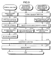
- FIG. 3 is a flowchart of process procedures of the reference-acquisition measurement process and the abnormality-identification measurement process shown in FIG. 2 .
- FIG. 3 additionally shows a normal analysis which is normally performed on the specimen along with the reference-acquisition measurement process and the abnormality-identification measurement process.
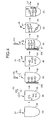
- FIG. 4 is a diagram for explaining the normal analysis shown in FIG. 3 .
- a cuvette 20 is transferred by the first-cuvette transfer system 32 from a cuvette supply unit not shown in FIG. 1 to a predetermined position on the BF table 25, where a first-reagent dispense process is performed, i.e., where the first reagent containing magnetic particles 61 is dispensed into the cuvette 20 by the first-reagent dispense/transfer system 28 (step S11).
- a first-reagent dispense process is performed, i.e., where the first reagent containing magnetic particles 61 is dispensed into the cuvette 20 by the first-reagent dispense/transfer system 28 (step S11).
- a specimen dispense process is performed; i.e., a specimen containing an antigen 62 is dispensed into the cuvette 20 on the BF table 25 in a manner such that the specimen dispense/transfer system 23, onto which the chip supplied from the chip holder 22 is mounted, sucks the specimen 62 out of the specimen vessel 21a which has been transferred to the predetermined position by the specimen transfer unit 21 to dispense the specimen 62 into the cuvette 20 (step S12).
- the liquid in the cuvette 20 is stirred by the stir system on the BF table 25, and then transferred to a middle circular line 24b on the immune reaction table 24 by the first-cuvette transfer system 32.
- the magnetic particles 61 and antigens 62 in the specimen are bound together in certain reaction time, and thus magnetic-particle carriers are generated.
- the cuvette 20 is transferred to the BF table 25 by the first-cuvette transfer system 32.
- the magnetic-particle carriers are collected by a magnetic collection system 25a on the BF table 25, and the BF separation is carried out by the BF cleaning nozzle 25c (step S13).
- the BF cleaning nozzle 25c step S13.
- unreacted substances 63 are removed out of the cuvette 20.
- a second-reagent dispense process which dispenses the second reagent into the cuvette 20 by the second-reagent dispense/transfer system 29, is performed and then the liquid in the cuvette 20 is stirred by the stir system (step S14).
- the second reagent is a labeled reagent containing a labeled antibody 65.
- the magnetic-particle carriers and the labeled antibodies 65 are bound to thereby generate immune complexes 67.
- the cuvette 20 is transferred to the inner circular line 24c on the immune reaction table 24 by the first-cuvette transfer system 32. After certain reaction time, the cuvette 20 is transferred to the BF table 25.
- the second BF cleaning process in which the magnetic-particle carriers are collected by the magnetic collection system 25b and the BF separation is performed by the BF cleaning nozzle 25d, is performed on the cuvette 20 (step S15).
- the labeled antibody 65 which is not bound with the magnetic-particle carrier is removed out of the cuvette 20.
- a substrate injection process which dispenses the substrate solution containing a substrate 66 into the cuvette 20 and stirs the liquid in the cuvette 20, is performed (step S16) as illustrated in (6) of FIG. 4 .
- the cuvette 20 is transferred by the first-cuvette transfer system 32 to an enzyme reaction table 30.
- the cuvette 20 is transferred by the second-cuvette transfer system 33 to the photometry system 31.
- the substrate 66 is bound with the immune complex 67 through the enzyme reaction, light L is emitted from the immune complex 67 as illustrated in (7) of FIG. 4 .
- a measurement process which measures the light L emitted from the cuvette 20 by the photometry system 31, is performed (step S17).
- the labeled antibody is bound with the magnetic-particle carrier to generate the immune complex.
- the immune complex is reacted with the substrate to generate light.
- the analysis unit 44 obtains the amount of the antigen by measuring the amount of the generated light.
- the normal analysis process which is performed on the specimen, involves the first-reagent dispense process (step S11), the specimen dispense process (step S12), the first BF cleaning process (step S13), the second-reagent dispense process (step S14), the second BF cleaning process (step S15), the substrate injection process (step S16), and the measurement process (step S17).
- FIG. 5 is a flowchart of process procedure of the identification-directed BF cleaning process shown in FIG. 3 .
- FIG. 6 is a diagram for explaining the reference-acquisition measurement process shown in FIG. 3 .
- the reference-acquisition measurement process performs a dummy-reagent dispense process (step S21) in place of the first-reagent dispense process in the normal analysis.
- the dummy-reagent dispense process dispenses a dummy reagent containing a magnetic particle 61a which does not react with the antigen contained in the low-concentration reagent and the high-concentration reagent.
- the reference-acquisition measurement process then injects a diluting solution to prevent the drying of the magnetic particle 61a which is dispensed in the dummy-reagent dispense process as illustrated in (2) of FIG. 6 , without performing the specimen dispense process (step S12) of the normal analysis.
- the reference-acquisition measurement process performs the identification-directed BF cleaning process (step S23) as illustrated in (3) of FIG. 6 .
- the identification-directed BF cleaning process performs the BF cleaning process, for which the removal defect is to be identified, following the process pattern determined by the control unit 41.
- the process control unit 42 determines whether the target of identification is the first BF cleaning process, the second BF cleaning process, or both the first BF cleaning process and the second BF cleaning process (step S231).
- step S231 On determining that the first BF cleaning process is to be examined (step S231: first BF cleaning), the process control unit 42 controls each of the systems of the measurement system 2 to perform the first BF cleaning process using the magnetic collection system 25a and the BF cleaning nozzle 25c (step S232). On determining that the second BF cleaning process is to be examined (step S231: second BF cleaning), the process control unit 42 controls each of the systems of the measurement system 2 to perform the second BF cleaning process using the magnetic collection system 25b and the BF cleaning nozzle 25d (step S233).
- step S231 On determining that both the first BF cleaning process and the second BF cleaning process are to be examined (step S231: first BF cleaning and second BF cleaning), the process control unit 42 controls each of the systems of the measurement system 2 to perform the first BF cleaning process (step S234) and subsequently the second BF cleaning process (step S235).
- the reference-acquisition measurement process then performs a low-concentration-reagent dispense process (step S24).
- the low-concentration-reagent dispense process dispenses a labeled antibody 65, a low-concentration reagent containing the antigens 62a of, for example, 0.3 ppm, and the magnetic particle 61 which can react with the antigen 62a in the low-concentration reagent as illustrated in (4) of FIG. 6 .
- the reference-acquisition measurement process performs an analysis process, after dispensing the low-concentration reagent, to allow the light emission of the antigen 62a in the low-concentration reagent, and measures the light-emission amount to acquire the light-emission amount corresponding to the antigen 62a of 0.3 ppm as the reference value. Specifically, the reference-acquisition measurement process stirs and leaves the contents of the cuvette 20 for a predetermined reaction time after the low-concentration-reagent dispense process.
- the magnetic particle 61, the antigen 62a in the low-concentration reagent, and the labeled antibody 65 react with each other to form the immune complex 67a as illustrated in (5) of FIG. 6 .
- the reference-acquisition measurement process performs the second BF cleaning process (step S15) in the same manner as in the normal analysis to remove the labeled antibody 65 which is not bound to the magnetic particle carrier.
- the immune complex 67a, being magnetically collected by the magnetic collection system of the BF table 25, are not removed out of the cuvette 20.
- the reference-acquisition measurement process performs the substrate injection process (step S16) as in the normal analysis.
- the substrate injection process injects the substrate solution containing the substrate 66 into the cuvette 20 as illustrate in (6) of FIG. 6 .
- the immune complex 67a in the same manner as the immune complex 67 shown in (6) of FIG. 4 , undergoes enzyme reaction to be bound with the substrate 66 to form a bound substance 671a which emits light La1 as illustrated in (7) of FIG. 6 .
- the reference-acquisition measurement process then performs the measurement process (step 17) to measure the light La1 emitted from the bound substance 671a, thereby acquires the light-emission amount serving as the reference value.
- the analyzer 1 can output clinically sufficient measurement result of other analyzed antigen. Therefore, the light-emission amount of the light La1 measured as the reference value in the measurement process of the reference-acquisition measurement process serves as a standard for determining the concentration of impurities which allows the output of clinically sufficient measurement result by the analyzer 1.
- FIG. 7 is a diagram for explaining the abnormality-identification measurement process shown in FIG. 3 .
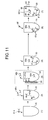
- the abnormality-identification measurement process performs the dummy-reagent dispense process (step S21) in the same manner as in the reference-acquisition measurement process as illustrate in FIG. 3 and ( 1 ) of FIG. 7 .
- the dummy-reagent dispense process dispenses the dummy reagent containing the magnetic particle 61a.
- the abnormality-identification measurement process then performs a high-concentration-reagent dispense process (step S32) in place of the specimen dispense process (step S12) of the normal analysis.
- the high-concentration-reagent dispense process dispenses the high-concentration reagent containing the antigen 62b in high concentrations into the cuvette 20 as illustrated in (2) of FIG. 7 .
- the high-concentration reagent contains the antigens 62b of, for example, 1 million ppm.
- the abnormality-identification measurement process then performs the identification-directed BF cleaning process (step S23) as illustrated in (3) of FIG. 7 , in the same manner as the identification-directed BF cleaning process in the reference-acquisition measurement process, following the process procedure shown in FIG. 5 .
- the abnormality-identification measurement process when the reference-acquisition measurement process performs the first BF cleaning process as the identification-directed BF cleaning process, the abnormality-identification measurement process performs the first BF cleaning process correspondingly; when the reference-acquisition measurement process performs the second BF cleaning process as the identification-directed BF cleaning process, the abnormality-identification measurement process performs the second BF cleaning process correspondingly; and when the reference-acquisition measurement process performs both the first and the second BF cleaning processes as the identification-directed BF cleaning process, the abnormality-identification measurement process performs both the first and the second BF cleaning processes correspondingly.
- the antigen 62b in the high-concentration reagent is removed out of the cuvette 20 and does not remain in the cuvette 20.
- the BF cleaning nozzle 25c, the BF cleaning nozzle 25d, or both are clogged, for example, the cleaning liquid may not be discharged properly, and/or the liquid and the cleaning liquid in the cuvette 20 may not be sucked out properly.
- there is fault in the BF cleaning i.e., if there is BF cleaning defect
- at least a part of the antigen 62b remains in the cuvette 20 as illustrated in (3) of FIG. 7 .
- the abnormality-identification measurement process performs the analysis process to allow the antigen 62b remaining in the cuvette 20 to emit light after the identification-directed BF cleaning process, and measures the light-emission amount corresponding to the antigen 62b remaining in the cuvette 20 as the abnormality-identification measurement value.
- the abnormality-identification measurement process performs an identifying-reagent dispense process (step S34).
- the identifying-reagent dispense process dispenses the identifying reagent, which is a reagent containing the magnetic particle 61 and the labeled antibody 65 as illustrated in (4) of FIG. 7 . Thereafter, the contents of the cuvette 20 is stirred and left for a predetermined reaction time.
- the magnetic particle 61, the remaining antigen 62b, and the labeled antibody 65 are bound with each other to form the immune complex 67b as illustrated in (5) of FIG. 7 .
- the abnormality-identification measurement process then performs the second BF cleaning process (step S15) in the same manner as in the normal analysis to remove the labeled antibody 65 which is not bound to the magnetic particle carrier.
- the immune complex 67b, being magnetically collected by the magnetic collection system 25b of the BF table 25, are not removed out of the cuvette 20.
- the abnormality-identification measurement process performs the substrate injection process (step S16) as in the normal analysis.
- the substrate injection process injects the substrate solution containing the substrate 66 into the cuvette 20 as illustrated in (6) of FIG. 7 .
- the immune complex 67b in the same manner as the immune complex 67 shown in (6) of FIG. 4 , undergoes enzyme reaction to be bound to the substrate 66 to form a bound substance 671b which emits light Lb1 as illustrated in (7) of FIG. 7 .
- the abnormality-identification measurement process performs the measurement process (step S17) to measure the light Lb1 emitted from the bound substance 671b as the abnormality-identification measurement value.
- the light-emission amount of the light Lb1 measured as the abnormality-identification measurement value corresponds to the amount of the antigen 62b remaining after the identification-directed BF cleaning process.
- the abnormality-identifying process shown in FIG. 2 is described.
- the identifying unit 45 determines that there is a removal defect in the BF cleaning process performed in the identification-directed BF cleaning process when the abnormality-identification measurement value acquired in the abnormality-identification measurement process is not within an acceptable range set based on the reference value acquired in the reference-acquisition measurement process.
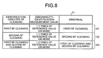
- the identifying unit 45 performs the abnormality-identifying process referring to a table T1 stored in the storage unit 46 and illustrated in FIG. 8 for a previously-set acceptable range.
- the reference value acquired in the reference-acquisition measurement process is the light-emission amount of the light La measured when the antigen 62a of 0.3 ppm is contained, and serves as a standard for determining the light-emission amount of impurities whose concentration does not obstruct an output of clinically sufficient measurement result of analyzed antigen(s).
- the table T1 shows standards for determination based on each reference value corresponding to each type of the identification-directed BF cleaning process.
- the abnormality-identifying process performed when the reference-acquisition measurement process and the abnormality-identification measurement process perform the first BF cleaning process as the identification-directed BF cleaning process as the identification-directed BF cleaning process.
- the first BF cleaning process is performed as the identification-directed BF cleaning process, as far as the abnormality-identification measurement value is less than 1.1 time the reference value, i.e., the light-emission amount corresponding to the antigen 62a of 0.3 ppm, the clinically sufficient measurement result can be output for analyzed antigen.
- the abnormality-identification measurement value is less than 1.1 times the reference value, the first BF cleaning process is expected to be capable of removing the antigen 62b in the high-concentration reagent to a clinically sufficient level.
- the identifying unit 45 determines that there is no removal defect attributable to the clogging of the BF cleaning nozzle and the like.
- the identifying unit 45 determines that the first BF cleaning process is incapable of removing the antigen 62b in the high-concentration reagent sufficiently and the remaining antigen 62b can affect the measurement result.
- the identifying unit 45 determines that there is a removal defect caused by the clogging of the BF cleaning nozzle 25c and the like as illustrated in a field R1 of Table T1.
- the analyzer 1 can output clinically sufficient measurement result for analyzed antigen.
- the identifying unit 45 determines that there is no removal defect in the second BF cleaning process caused by the clogging of the BF cleaning nozzle and the like.
- the identifying unit 45 determines that the second BF cleaning process is incapable of removing the antigen 62b in the high-concentration reagent sufficiently and the remaining antigen 62b can clinically affect the measurement result. Thus, the identifying unit 45 determines that there is a removal defect caused by the clogging of the BF cleaning nozzle 25d and the like as illustrated in a field R2 of Table T1.
- the analyzer 1 can output clinically sufficient measurement result for analyzed antigen.
- the identifying unit 45 determines that there is no removal defect in the first and the second BF cleaning processes caused by the clogging of the BF cleaning nozzle and the like.
- the identifying unit 45 determines that the first BF cleaning process, the second BF cleaning process, or both are incapable of removing the antigen 62b in the high-concentration reagent sufficiently and the remaining antigen 62b can clinically affect the measurement result.
- the identifying unit 45 determines that there is a removal defect caused by the clogging of the BF cleaning nozzles 25c, 25d and the like as illustrated in a field R3 of Table T1.
- the analyzer 1 determines whether the BF cleaning process removes the contents of the cuvette to a clinically sufficient level based on the reference value, i.e., the light-emission amount corresponding to the concentration of impurities which allows the output of clinically sufficient measurement result, and the abnormality-identification measurement value, i.e., the light-emission amount after the BF cleaning process is actually performed on the high-concentration reagent.
- the reference-acquisition measurement process and the abnormality-identification measurement process perform processes other than the BF cleaning process, for which the abnormality is to be identified, substantially in the same manner. Therefore, the contribution of other processes to the abnormality does not need to be considered, and the removal defect of the BF cleaning process can be examined correctly.
- the presence/absence of the abnormality in the BF cleaning process can be identified based on the measurement result obtained by the photometry system 31. Therefore, an independent spectrophotometer for colorimetric measurement is not required to be provided apart from the analyzer itself, unlike the conventional technology. Thus, according to the first embodiment, the abnormality of the analyzer can be identified correctly and easily.
- the first embodiment is a case where the employed low-concentration reagent and the high-concentration reagent which contain as their component, the antigen reacting with the magnetic particle 61, in the same manner as the antigen contained in actual specimen such as blood and urine.
- the low-concentration reagent and the high-concentration reagent may contain as their component, a labeled substance which reacts with the substrate (enzyme) acting as a light-emitting substrate.
- the analyzer 1 performs the reference-acquisition measurement process using a reagent which contains labeled substances in predetermined very low concentrations as the low-concentration reagent. Further, the analyzer 1 performs the abnormality-identification measurement process using a reagent which contains labeled substances in predetermined high concentrations as the high-concentration reagent.
- the reference-acquisition measurement process performs the dummy-reagent dispense process (step S121) for dispensing the dummy reagent containing the magnetic particle 61a, and after the injection of diluting solution, performs the identification-directed BF cleaning process (step S123) as illustrated in FIG. 9 and ( 1 ) to (3) of FIG. 10 , in the same manner as the case illustrated in FIG. 3 and ( 1 ) to (3) of FIG. 6 .
- the reference-acquisition measurement process performs the low-concentration-reagent dispense process (step S124) to dispense the low-concentration reagent containing the labeled antibody 65a of 0.3 ppm into the buffer solution as illustrate in (4) of FIG. 10 .
- the labeled antibody 65a and the substrate 66 undergo enzyme reaction to be bound with each other and emit light.
- the substrate injection process (S16) is first performed, in which the substrate solution containing the substrate 66 is injected into the cuvette 20 as illustrated in FIG. 9 and ( 6 ) of FIG. 10 .
- the analyzer 1 After the substrate 66 and the labeled antibody 65a undergo predetermined enzyme reaction to form a bound substance 651a which emits light La2, the analyzer 1 performs the measurement process (step S17) to measure the light La2, to thereby acquire the light-emission amount as the reference value.
- the analyzer 1 can acquire the light-emission amount as the reference value only through the enzyme reaction between the labeled antibody 65a and the substrate 66.
- the analyzer 1 does not need to perform processes required when the low-concentration reagent contains the antigen 62a to make the antigen 65a emit light. These processes include the process for injecting the magnetic particle 61 and the labeled antibody 65 as illustrated in (4) of FIG. 6 , and the second BF cleaning process (step S15) for removing the labeled antibody 65 which is not bound to the magnetic particle carrier.
- the abnormality-identification measurement process performs the dummy-reagent dispense process (step S121) to dispense the dummy reagent containing the magnetic particle 61a as illustrate in FIG. 9 and ( 1 ) to (3) of FIG. 11 , in the same manner as illustrated in FIG. 3 and ( 1 ) of FIG. 7 .
- the abnormality-identification measurement process proceeds to the high-concentration-reagent dispense process (step S132) to dispense the high-concentration reagent containing the labeled antibody 65b of, for example, 1 million ppm into the cuvette 20 as illustrated in FIG. 9 and ( 2 ) of FIG. 11 .
- the identification-directed BF cleaning process (step S123) is performed as illustrated in FIG. 9 and ( 3 ) of FIG. 11 .
- the labeled antibody 65b does not have magnetism. Therefore, if the BF cleaning process is not defective, all the labeled antibodies 65b are removed in the identification-directed BF cleaning process.
- a buffer-solution dispense process (step S134) is performed to make the condition the same as that in the low-concentration-reagent dispense process in the reference-acquisition measurement process.
- the buffer-solution dispense process dispenses the buffer solution alone as illustrated in (4) of FIG. 11 .
- the substrate injection process (step S16) is performed as illustrated in FIG.
- the analyzer 1 performs the measurement process (step S17) to measure the light Lb2 to thereby acquire the light-emission amount as the reference value.
- the analyzer 1 can acquire the light-emission amount serving as the abnormality-identification measurement value only through the enzyme reaction between the labeled antibody 65b and the substrate 66. In other words, the analyzer 1 does not need to perform processes required when the high-concentration reagent contains the antigen 62b to make the antigen 62b remaining in the cuvette 20 emit light. These processes include the process for injecting the magnetic particle 61 and the labeled antibody 65 as illustrated in (4) of FIG. 7 , and the second BF cleaning process (step S15) for removing the labeled antibody 65 which is not bound to the magnetic particle carrier.
- the analyzer 1 identifies the abnormality in each of the BF cleaning processes performed in the identification-directed BF cleaning process by referring to the table T1 illustrated in FIG. 8 and comparing the reference value acquired as illustrated in (7) of FIG. 10 and the abnormality-identification measurement value acquired as illustrated in (7) of FIG. 11 .
- the analyzer 1 can eliminate the second BF cleaning process shown in FIG. 3 , (5) of FIG. 6 , and ( 5 ) of FIG. 7 in the reference-acquisition measurement process and the abnormality-identification measurement process, whereby the analyzer 1 can identify the abnormality in the BF cleaning process more promptly.
- the second BF cleaning process is performed in addition to the identification-directed BF cleaning process as illustrated in FIGS. 3 , 6 , and 7 , and if there is an abnormality in the performance of the BF cleaning process to remove unreacted substances, not only that the abnormality-identification measurement process cannot measure the remaining amount of the high-concentration reagent correctly, but that the reference-acquisition measurement process may not be able to measure the reference value correctly.
- the employed low-concentration reagent and high-concentration reagent contain the labeled antibodies as the component as illustrated in FIGS. 9 , 10 , and 11 , the analyzer 1 does not need to perform the BF cleaning process other than the identification-directed BF cleaning process. Therefore, even if there is an abnormality in the performance of BF cleaning process to remove unreacted substances, the reference value and the abnormality-identification measurement value can be acquired without negative influence therefrom, and the abnormality in the BF cleaning process can be identified even more correctly.
- the labeled antibody can emit light simply by binding to the substrate (enzyme) as illustrated in FIGS. 9 , 10 , and 11 .
- the magnetic particle and the labeled antibody which make the antigen emit light are not required when the low-concentration reagent and the high-concentration reagent contain the labeled antibody as their component.
- the analyzer 1 does not need to use the reagent containing the magnetic particle and the labeled antibody for identifying the abnormality in the BF cleaning process, whereby the amount of reagent employed in abnormality identification of the BF cleaning process can be reduced.
- a second embodiment is described. Described below as the second embodiment is a case where presence/absence of cleaning defect of a dispense system is identified.
- the dispense system dispenses liquid in analysis processes on a specimen.
- the light-emission amount of the low-concentration reagent is employed as a reference value.
- a cleaning process is performed on the dispense system.
- a dispense/transfer system dispenses zero-concentration reagent which contains no antigen. Thereafter, if the light-emission amount is equal to or higher than predetermined times the reference value, the analyzer determines that there is a cleaning defect of the dispense system.
- the analyzer of the second embodiment has the same configuration as that of the analyzer 1 shown in FIG. 1 .
- each of the systems included in the measurement system 2 performs the reference-acquisition measurement process (step S42) under the control of the process control unit 42 to acquire the measurement result obtained using the low-concentration reagent containing antigens in very low concentrations, as a reference value. Then, each of the systems included in the measurement system 2 performs a high-concentration-reagent use process (step S44) to inject the high-concentration reagent containing antigens in high concentrations using a dispense/transfer system for which the cleaning defect is to be identified.
- each of the systems included in the measurement system 2 performs the abnormality-identification measurement process (step S46) to measure the light-emission amount as the abnormality-identification measurement value, after a cleaned dispense/transfer system dispenses a zero-concentration reagent into a cuvette different from the cuvette in which the high-concentration reagent is dispensed.
- the identifying unit 45 performs the abnormality-identifying process (step S48) to identify the presence/absence of cleaning defect of the dispense system based on whether the abnormality-identification measurement value acquired in the abnormality-identification measurement process is within an acceptable range set based on the reference value acquired in the reference-acquisition measurement process.
- FIG. 13 is a flowchart of process procedure of the reference-acquisition measurement process, the high-concentration-reagent use process, and the abnormality-identification measurement process shown in FIG. 12 .
- FIG. 14 is a diagram for explaining the reference-acquisition measurement process shown in FIG. 13
- FIG. 15 is a diagram for explaining the high-concentration-reagent use process shown in FIG. 13
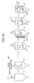
- FIG. 16 is a diagram for explaining the abnormality-identification measurement process shown in FIG. 13 .
- the reference-acquisition measurement process performs the first-reagent dispense process (step S51) to dispense a first reagent containing the magnetic particle 61 which can react with an antigen contained in the low-concentration reagent and the high-concentration reagent. Further, the reference-acquisition measurement process performs the low-concentration-reagent dispense process (step S52) to dispense a low-concentration reagent containing the antigen 62a of, for example, 0.3 ppm to the cuvette 20 using a probe of a dispense/transfer system, for which the cleaning defect is to be identified, as illustrated in (2) of FIG. 14 . The contents of the cuvette 20 is stirred and left for a predetermined reaction time, and the magnetic particle 61 and the antigen 62a in the low-concentration reagent are bound with each other to form a magnetic particle carrier.
- the analyzer 1 can output clinically sufficient measurement result of other analyzed antigen.
- the reference-acquisition measurement process performs an analysis process to make the antigen 62a in the low-concentration reagent emit light, and measures the light-emission amount to acquire the light-emission amount corresponding to the antigen 62a of 0.3 ppm as the reference value.
- the reference-acquisition measurement process performs the second-reagent dispense process (step S54) to dispense the second reagent containing the labeled antibody 65 into the cuvette 20 using the second-reagent dispense/transfer system 29 as illustrated in (4) of FIG. 14 . Thereafter, the contents of the cuvette 20 is stirred and left for a predetermined reaction time. Then, the magnetic particle carrier and the labeled antibody 65 are bound with each other to form the immune complex 67a as illustrated in (5) of FIG. 14 .
- the reference-acquisition measurement process performs the second BF cleaning process (step S55) as in the normal analysis to remove the labeled antibody 65 which is not bound to the magnetic particle carrier as illustrated in (5) of FIG. 14 .
- the immune complex 67a being magnetically collected by the magnetic collection system of the BF table 25, are not removed out of the cuvette 20.
- the reference-acquisition measurement process then performs the substrate injection process (step S56) to inject the substrate solution containing the substrate 66 to the cuvette 20 as illustrated in (6) of FIG. 14 , as in the normal analysis.
- the immune complex 67a in the same manner as the immune complex 67 shown in (6) of FIG.
- the reference-acquisition measurement process then performs the measurement process (step S57) to measure the light La3 emitted from the bound substance 672a, to thereby acquire the light-emission amount as the reference value.
- the high-concentration-reagent use process is described with reference to FIGS. 13 and 15 .
- the high-concentration-reagent use process performs the first-reagent dispense process (step S51) to dispense the first reagent containing the magnetic particle 61 as illustrated in FIG. 13 and ( 1 ) of FIG. 15 in the same manner as in the reference-acquisition measurement process.
- the high-concentration-reagent use process performs the high-concentration-reagent dispense process (step S62) to dispense the high-concentration reagent containing the antigen 62b in high concentrations to the cuvette 20 using the probe of a dispense/transfer system, for which the cleaning defect is to be identified, as illustrate in (2) of FIG. 15 .
- the high-concentration reagent contains the antigens 62b of, for example, 1 million ppm.
- the probe of the dispense/transfer system which dispenses the high-concentration reagent is cleaned before the next liquid dispensing.
- the high-concentration-reagent use process performs the second-reagent dispense process (step S54), the second BF cleaning process (step S55), and the substrate injection process (step S56) in the same manner as in the reference-acquisition measurement process as illustrated in (4) to (6) of FIG. 15 .
- the immune complex 67b is bound to the substrate 66 and emits light L as illustrated in (7) of FIG. 15 .
- the high-concentration-reagent use process finishes without measuring the light L.
- the abnormality-identification measurement process is described with reference to FIGS. 13 and 16 .
- the abnormality-identification measurement process performs the first-reagent dispense process (step S51) to dispense the first reagent containing the magnetic particle 61 as illustrated in FIG. 13 and ( 1 ) of FIG. 16 in the same manner as in the reference-acquisition measurement process and the high-concentration-reagent use process.
- the abnormality-identification measurement process performs the zero-concentration-reagent dispense process (step S72) to dispense the zero-concentration reagent using the probe of a dispense/transfer system, for which the cleaning defect is to be identified, as illustrated in (2) of FIG. 16 .
- the antigen 62b in the high-concentration reagent dispensed by the probes Pa and Pb before the zero-concentration reagent is dispensed may not be removed sufficiently, and remain on the probes PA and Pb.
- the abnormality-identification measurement process performs the analysis process to make the antigen 62b remaining on the probes Pa and Pb and entering the cuvette 20 emit light, and measures the light emission amount as the abnormality-identification measurement value.
- the contents of the cuvette 20 is stirred and left for a predetermined reaction time so that the magnetic particle 61 and the antigen 62b remaining on the probes Pa and Pb and entering the cuvette 20 are bound with each other to form the magnetic particle carrier 61b.
- the abnormality-identification measurement process performs the second-reagent dispense process (step S54) to dispense the second reagent containing the labeled antibody 65 into the cuvette 20 as illustrated in (4) of FIG. 16 .
- the magnetic particle carrier 61b and the labeled antibody 65 are bound with each other to form the immune complex 67b.
- the abnormality-identification measurement process performs the second BF cleaning process (step S55) as illustrated in (5) of FIG. 16 in the same manner as in the reference-acquisition measurement process to remove the labeled antibody 65 which is not bound to the magnetic particle carrier 61b.
- the immune complex 67b being magnetically collected by the magnetic collection system 25b of the BF table 25, are not removed out of the cuvette 20.
- the abnormality-identification measurement process performs the substrate injection process (step S56) to inject the substrate solution containing the substrate 66 into the cuvette 20 as illustrated in (6) of FIG. 16 in the same manner as in the reference-acquisition measurement process.
- the immune complex 67b in the same manner as the immune complex 67 shown in (6) of FIG. 4 , undergoes enzyme reaction to be bound to the substrate 66 to form a bound substance 672b which emits light Lc3 as illustrated in (7) of FIG. 16 .
- the abnormality-identification measurement process then performs the measurement process (step S77) to measure the light Lc3 emitted from the bound substance 672b thereby to acquire the light-emission amount which is the abnormality-identification measurement value.
- the light-emission amount of the light Lc3 measured as the abnormality-identification measurement value corresponds to the amount of the antigen 62b which remains on the probe after the probe, for which the cleaning defect is to be identified, is cleaned, and enters the cuvette 20 when the probe dispenses the liquid for the next time.
- the abnormality-identifying process shown in FIG. 12 is described.
- the identifying unit 45 determines that there is a cleaning defect in the probe which dispenses the high-concentration reagent when the abnormality-identification measurement value acquired in the abnormality-identification measurement process is not within an acceptable range set based on the reference value acquired in the reference-acquisition measurement process.
- the identifying unit 45 performs the abnormality-identifying process by referring to a table T2 stored in the storage unit 46 and illustrated in FIG. 18 for the previously-set acceptable range.
- the reference value acquired in the reference-acquisition measurement process is the light-emission amount of light La emitted when the antigen 62a of 0.3 ppm is contained, and serves as a standard for determining the light-emission amount of impurities whose concentration allows an output of clinically sufficient measurement results of analyzed antigen(s).
- the table T2 shows the standard for determination based on the reference value.
- the identifying unit 45 can output clinically sufficient measurement result of the analyzed antigen.
- the abnormality-identification measurement value is less than 1.1 times the reference value, it is considered that the antigen 62b of the high-concentration reagent remaining on the probe is cleaned and removed from the probe to a clinically sufficient level in the dispense/transfer system which dispenses the high-concentration reagent. Therefore, the identifying unit 45 determines that there is no cleaning defect in the dispense/transfer system which dispenses the high-concentration reagent.
- the identifying unit 45 determines that there is a probe cleaning defect in the dispense/transfer system which dispenses the high-concentration reagent.
- the analyzer determines whether the substances in the previously-dispensed liquid are removed in the cleaning process of the dispense/transfer system to a clinically sufficient level or not, based on the reference value, i.e., the light-emission amount corresponding to the concentration of impurities which would not obstruct the output of clinically sufficient measurement result, and the abnormality-identification measurement value, i.e., the light-emission amount obtained by dispensing the zero-concentration reagent after actually dispensing the high-concentration reagent using the dispense/transfer system, for which the defect is to be identified.
- the reference value i.e., the light-emission amount corresponding to the concentration of impurities which would not obstruct the output of clinically sufficient measurement result
- the abnormality-identification measurement value i.e., the light-emission amount obtained by dispensing the zero-concentration reagent after actually dispensing the high-concentration reagent using the dispense/transfer system, for which the
- processes other than the liquid dispense process of the dispense/transfer system, for which the abnormality is to be identified are performed substantially in the same manner. Therefore, the contribution of other processes on the abnormality does not need to be considered, and the cleaning defect in the dispense/transfer system can be examined correctly. Further, according to the second embodiment, the presence/absence of the cleaning defect of the dispense/transfer system can be identified based on the measurement result obtained by the photometry system 31. Therefore, an independent spectrophotometer for colorimetric measurement is not required to be provided apart from the analyzer itself, unlike the conventional technology. Thus, according to the second embodiment, the abnormality of the analyzer can be identified correctly and easily.
- the antigens reacting with the magnetic particle 61, the low-concentration reagent, zero-concentration reagent, and the high-concentration reagent containing as their component may be employed.
- the analyzer 1 performs the reference-acquisition measurement process using a reagent containing labeled substances in predetermined very low concentrations as the low-concentration reagent.
- the analyzer 1 performs the high-concentration-reagent use process using a reagent containing labeled substances in predetermined high concentrations as the high-concentration reagent, and then performs the abnormality-identification measurement process using the zero-concentration reagent containing no labeled substance.
- the low-concentration-reagent dispense process (step S352) is performed to dispense the low-concentration reagent containing the labeled antibodies 65a of, for example, 0.3 ppm to the buffer solution. Then, as shown in FIG. 19 and ( 6 ) of FIG.
- the analyzer 1 performs the substrate injection process (step S56) to inject the substrate solution containing the substrate 66 to the cuvette 20 in order to acquire the light-emission amount corresponding to the labeled antibody 65a of 0.3 ppm as the reference value.
- the substrate 66 and the labeled antibody 65a are bound with each other to form a bound substance 652a which emits light La4 as shown in (7) of FIG. 20 .
- the analyzer 1 performs the measurement process (step S57) to measure the light La4, to thereby acquire the light-emission amount serving as the reference value. As shown in FIGS.
- the analyzer 1 when the employed low-concentration reagent contains as its component, the labeled antibody 65a which is bound with the substrate 66 acting as the light-emitting substrate, the analyzer 1 can acquire the light-emission amount as the reference value simply through the enzyme reaction between the labeled antibody 65a and the substrate 66. In other words, when the employed low-concentration reagent contains the labeled antibody 65a as its component, the analyzer 1 does not need to perform processes required when the low-concentration reagent contains the antigen 62a to make the antigen 65a emit light.
- These processes include the process for injecting the magnetic particle 61, which is the first reagent (step S51), the process for injecting the labeled antibody 65, which is the second reagent (step S54), and the second BF cleaning process (step S55) for removing the labeled antibody 65 which is not bound to the magnetic particle carrier as illustrated in FIG. 13 , and ( 1 ), (4), and (5) of FIG. 14 .
- the high-concentration-reagent dispense process (step S362) is performed to dispense the high-concentration reagent containing the labeled antibodies 65b of, for example, 1 million ppm into the buffer solution. Then, as illustrated in FIG. 19 and ( 6 ) of FIG.
- the analyzer 1 performs the substrate injection process (step S56) to inject the substrate solution containing the substrate 66 into the cuvette 20 in order to make the labeled antibody 65b of 1 million ppm emit light.
- the labeled antibody 65b is bound to the substrate 66 and emits light L as illustrated in (7) of FIG. 21 .
- the high-concentration-reagent use process finishes without measuring the light L. As shown in FIGS.
- the analyzer 1 does not need to perform the process for injecting the magnetic particle 61 which is the first reagent (step S51), the process for injecting the labeled antibody 65 which is the second reagent (step S54), and the second BF cleaning process (step S55) for removing the labeled antibody 65 which is not bound to the magnetic particle carrier as illustrated in FIG. 13 , and ( 1 ), (4), and (5) of FIG. 15 .
- the abnormality-identification measurement process shown in FIG. 19 is described with reference to FIGS. 19 and 22 .
- the analyzer 1 performs a zero-concentration-reagent dispense process (step S372) to dispense the zero-concentration reagent containing no labeled antibody as illustrated in FIG. 19 and ( 2 ) of FIG. 22 .
- the analyzer 1 performs an analysis process to make the labeled antibody 65b remaining on the probe and entering into the cuvette 20 in the zero-concentration-reagent dispense process emit light, and measures the abnormality-identification measurement value.
- the analyzer 1 performs the substrate injection process (step S56) to inject the substrate solution containing the substrate 66 into the cuvette 20 as illustrated in FIG.
- the substrate 66 and the labeled antibody 65b entered the cuvette 20 form a bound substance 652b which emits light Lc4 as illustrated in (7) of FIG. 22 .
- the analyzer 1 performs the measurement process (step S77) to measure the light Lc4 to thereby acquire the light-emission amount serving as the abnormality-identification measurement value. As shown in FIGS.
- the analyzer 1 when the employed zero-concentration reagent contains no labeled antibody as its component, the analyzer 1 can acquire the light-emission amount, i.e., the abnormality-identification measurement value only through the enzyme reaction between the substrate 66 and the labeled antibody 65b which enters the cuvette 20 due to probe-cleaning defect. In other words, the analyzer 1 does not need to perform processes to make antigen 62b emit light when the employed zero-concentration reagent contains no labeled antibody as its component.
- These process include the process for injecting the magnetic particle 61, which is the first reagent (step S51), the process for injecting the labeled antibody 65, which is the second reagent (step S54), and the second BF cleaning process (step S55) for removing the labeled antibody 65 which is not bound to the magnetic particle carrier as illustrated in FIG. 13 , and ( 1 ), (4), and (5) of FIG. 16 .
- the analyzer 1 identifies the abnormality in the probe-cleaning process by referring to the table T2 illustrated in FIG. 18 and comparing the reference value acquired as illustrated in (7) of FIG. 20 , and the abnormality-identification measurement value acquired as illustrated in (7) of FIG. 22 .
- the analyzer 1 can eliminate the second BF cleaning process as illustrated in FIG. 13 , (5) of FIG. 14 , (5) of FIG. 15 , and ( 5 ) of FIG. 16 in the reference-acquisition measurement process, the high-concentration-reagent use process, and the abnormality-identification measurement process, whereby the analyzer 1 can identify the abnormality in the BF cleaning process even more promptly.
- the analyzer 1 can acquire the reference value and the abnormality-identification measurement value without being affected therefrom, and identify the abnormality in the probe cleaning even more accurately.
- the labeled antibody can be bound to the enzyme and emit light as it is. Therefore, when the low-concentration reagent, the high-concentration reagent, and the zero-concentration reagent containing the labeled antibody as their component are employed, the magnetic particle and the labeled antibody required for making the antigen emit light are not required.
- the analyzer 1 does not need to use the reagent containing the magnetic particle and the labeled antibody for identifying the abnormality in the probe-cleaning process, whereby the amount of reagent used for identifying the abnormality in the probe-cleaning process can be reduced.
- the analyzer described in the above embodiment can be realized by a computer system such as a personal computer and a workstation, which executes predetermined programs.
- the computer system reads out programs stored in a predetermined storage medium to realize the procedure of the analyzer.
- the predetermined storage medium can be "a portable physical medium” such as a flexible disk (FD), a CD-ROM, an MO disk, a DVD disk, a magneto-optical disk, and an IC card, or a "communication medium” such as a hard disk drive (HDD), which is stored inside or outside the computer system, and temporarily stores programs therein for transmission of the programs, or any storage medium which can store computer-readable programs therein.
- the computer system obtains programs from other computer system which is connected therewith via a network, and executes the obtained programs to realize the procedure of the analyzer.
- the analyzer according to the present invention is useful for medical analyzers including no colorimetric measurement unit, and in particular is suitable for identifying an abnormality in an analyzer promptly and easily.
Landscapes
- Engineering & Computer Science (AREA)
- Quality & Reliability (AREA)
- Physics & Mathematics (AREA)
- Health & Medical Sciences (AREA)
- Life Sciences & Earth Sciences (AREA)
- Chemical & Material Sciences (AREA)
- Analytical Chemistry (AREA)
- Biochemistry (AREA)
- General Health & Medical Sciences (AREA)
- General Physics & Mathematics (AREA)
- Immunology (AREA)
- Pathology (AREA)
- Automatic Analysis And Handling Materials Therefor (AREA)
Abstract
Description
- The present invention relates to identification of an abnormality in an analyzer which analyzes a specimen based on optical measurement.
- An analyzer can analyze a number of specimens at the same time, and further, can analyze many components immediately and accurately. The analyzer is used for various tests such as an immunological test, a biochemical test, and a blood-transfusion test. For example, the analyzer which performs the immunological test includes a reaction system in which the specimen is reacted with a reagent in a reaction vessel, a removal system in which unreacted substances are removed out of the reaction vessel, and a photometry system in which the amount of light emission from an immune complex obtained through reaction between the specimen and each reagent is measured. These systems are arranged on plural turntables, respectively. The analyzer further includes plural dispense/transfer systems which dispense or transfer the specimen, the reagent, or a reaction liquid into each of the systems. The analyzer performs immunological tests for various contents of the analysis (e.g., see Patent Document 1).
- Patent Document 1: Japanese Patent Application Laid-open No.
2003-83988 - Conventionally, the abnormality of the analyzer has been examined as follows. The analyzer performs a series of analysis processes, which are to be performed on an actual specimen, on a reference specimen with which a known analysis result should be produced, and then it is checked whether the analysis result produced by the analyzer is consistent with the known result. In other words, conventionally, when the analysis result obtained from the actual analysis of the reference specimen is consistent with the known analysis result, an operator of the analyzer determines that the analyzer functions normally whereas when the analysis result obtained from the actual analysis of the reference specimen is inconsistent with the known analysis result, the operator determines that the analyzer functions abnormally.
- In the conventional method with the reference specimen, however, the operator can determine that there is an abnormality in the analyzer, but can hardly know which process or system of the analyzer exactly causes the abnormality. Especially, it is difficult to properly identify the abnormality in the analyzer which performs the immunological test, since the analyzer of the kind has a complex configuration in which various factors such as reaction time, a reagent to be used, a system to be used, and a timing to use the system are different depending on the contents of the analysis processes.
- Further, conventionally, dispense accuracy of the dispense/transfer system is examined by dispensing the reagent which has predetermined absorbance characteristics into the reaction vessel, and referring to a measurement result obtained through a colorimetric method. The analyzer which performs the immunological test, however, does not include a colorimetric measurement unit. Therefore, to examine the dispense accuracy, the operator needs to perform the colorimetric measurement using a spectral photometer which is not included in the analyzer.
- The present invention is made in view of the above problems of the conventional technology, and an object of the present invention is to provide an abnormality-identifying method, an analyzer, and a reagent which can identify an abnormality of an analyzer properly and easily.
- To solve the problems as described above and to achieve an object, an abnormality-identifying method according to one aspect of the present invention identifies an abnormality in an analyzer which analyzes a specimen based on optical measurement. The method includes a reference-acquisition measurement process step that acquires a reference value which is a measurement result obtained by using a low-concentration reagent containing a component in predetermined very low concentrations, an abnormality-identification measurement process step that acquires an abnormality-identification measurement value which is a measurement result obtained through an analysis process using a high-concentration reagent containing the component in predetermined high concentrations, and an abnormality identifying step that identifies an abnormality in an analysis process concerning removal of the high-concentration reagent based on whether the abnormality-identification measurement value is within an acceptable range set based on the reference value.
- Further, in the abnormality-identifying method according to the present invention, the reference-acquisition measurement process step may include a first measurement step that measures a light-emission amount as the reference value after an analysis process which allows the component to emit light. Further, the abnormality-identification measurement process step may includes a removal step that, after injecting the high-concentration reagent into a reaction vessel, removes the component in the high-concentration reagent in the reaction vessel by performing a same process as a removal process for removing unreacted substance in the reaction vessel, among analysis processes performed on the specimen, and a second measurement step that measures a light-emission amount as the abnormality-identification measurement value after an analysis process which allows the component to emit light. Further, the abnormality identifying step may identify a removal defect in the removal process among the analysis processes performed on the specimen when the abnormality-identification measurement value is not within the acceptable range.
- Further, in the abnormality-identifying method according to the present invention, the removal process may include a first removal process and a second removal process, and the removal step may be one of a first removal step which performs a same process as the first removal process, a second removal step which performs a same process as the second removal process, and a third removal step which performs a same process as the first removal process and a same process as the second removal process.
- Further, in the abnormality-identifying method according to the present invention, the abnormality-identification measurement process step may identify a removal defect in the first removal process among the analysis processes performed on the specimen, when the removal step is the first removal step and the abnormality-identification measurement value is not within the acceptable range, a removal defect in the second removal process among the analysis processes performed on the specimen, when the removal step is the second removal step and the abnormality-identification measurement value is not within the acceptable range, and a removal defect in at least one of the first removal process and the second removal process, when the removal step is the third removal step and the abnormality-identification measurement value is not within the acceptable range.
- Further, in the abnormality-identifying method according to the present invention, the reference-acquisition measurement process step may include a first measurement step that measures a light-emission amount as the reference value after an analysis process to allow the component emit light. The abnormality-identification measurement process step may include a high-concentration-reagent injection step that injects the high-concentration reagent into a reaction vessel using a liquid injection system which injects liquid into the reaction vessel, a zero-concentration-reagent injection step that, after the high-concentration-reagent injection step, injects a zero-concentration reagent containing none of the component in a reaction vessel which is different from the reaction vessel in which the high-concentration reagent is injected using the liquid injection system which is cleaned, and a second measurement step that measures a light-emission amount as the abnormality-identification measurement value of the reaction vessel into which the zero-concentration reagent is injected after an analysis process to allow the component to emit light. The abnormality identifying step may identify a defect in a cleaning process of the liquid injection system among the analysis processes performed on the specimen, when the abnormality-identification measurement value is not within the acceptable range.
- Further, in the abnormality-identifying method according to the present invention, the component may be a labeled substance which is bound to a light-emitting substrate.
- Further, an analyzer according to another aspect of the present invention analyzes a specimen based on optical measurement. The analyzer includes a measurement unit that acquires a reference value which is a measurement result obtained by using a low-concentration reagent containing a component in predetermined very low concentrations, and acquires an abnormality-identification measurement value which is a measurement result obtained through analysis process using a high-concentration reagent containing the component in predetermined high concentrations; and an identifying unit that identifies an abnormality in an analysis process concerning removal of the high-concentration reagent based on whether the abnormality-identification measurement value is within an acceptable range set based on the reference value.
- Further, the analyzer according to the present invention may further include a removing unit that performs a removal process among analysis processes performed on the specimen to remove unreacted substance from a reaction vessel. The removing unit may remove, after the high-concentration reagent is injected into the reaction vessel, a component of the high-concentration reagent in the reaction vessel by performing a same process as the removal process. The measurement unit may measure a light-emission amount as the reference value after an analysis process which allows the component in the low-concentration reagent to emit light, and measures a light-emission amount as the abnormality-identification measurement value after the removing unit removes the component of the high-concentration reagent and an analysis process is performed to allow the component to emit light. The identifying unit may identify a removal defect in the removal process among the analysis processes performed on the specimen when the abnormality-identification measurement value is not within the acceptable range.
- Further, in the analyzer according to present invention, the removal process may include a first removal process and a second removal process, and the removing unit may perform at least one of a same process as the first removal process and a same process as the second removal process, to remove the component of the high-concentration reagent in the reaction vessel.
- Further, in the analyzer according to the present invention, the identifying unit may identify: a removal defect in the first removal process among the analysis processes performed on the specimen, when the removing unit performs the same process as the first removal process and the abnormality-identification measurement value is not within the acceptable range; a removal defect in the second removal process among the analysis processes performed on the specimen, when the removing unit performs the same process as the second removal process and the abnormality-identification measurement value is not within the acceptable range; and a removal defect in one or both of the first removal process and the second removal process among the analysis processes performed on the specimen, when the removing unit performs the same process as the first removal process and the same process as the second removal process and the abnormality-identification measurement value is not within the acceptable range.
- Further, the analyzer according to the present invention, may further include a liquid injecting unit that injects liquid into the reaction vessel. The liquid injecting unit may inject the high-concentration reagent into the reaction vessel, may be cleaned after the high-concentration-reagent injection, and may subsequently inject a zero-concentration reagent, which contains none of the component, into a different reaction vessel from the reaction vessel into which the high-concentration reagent is injected. The measurement unit may measure a light-emission amount after an analysis process to allow the component in the low-concentration reagent to emit light as the reference value, and measures a light-emission amount from the reaction vessel into which the zero-concentration reagent is injected as the abnormality-identification measurement value, after an analysis process to allow the component to emit light. The identifying unit may identify a defect in a cleaning process performed by the liquid injecting unit among the analysis processes performed on the specimen, when the abnormality-identification measurement value is not within the acceptable range.
- Further, in the analyzer according to the present invention, the component may be a labeled substance which is bound to a light-emitting substrate.
- According to the present invention, a measurement result is obtained as a reference value using a low-concentration reagent containing a component in predetermined very low concentrations, and a measurement result is obtained as an abnormality-identification measurement value using a high-concentration reagent containing the component in predetermined high concentrations through an analysis process. An abnormality in the analysis process concerning removal of the high-concentration reagent is identified based on whether the abnormality-identification measurement value is within an acceptable range set based on the reference value. Therefore, the abnormality in the analyzer can be identified correctly and easily.
-
-
FIG. 1 is a schematic diagram of configuration of an analyzer according to a first embodiment of the present invention; -
FIG. 2 is a flowchart of a process procedure of an abnormality-identifying process in the analyzer illustrated inFIG. 1 ; -
FIG. 3 is a flowchart of a process procedure of a reference-acquisition measurement process and an abnormality-identification measurement process illustrated inFIG. 2 ; -
FIG. 4 is a diagram for explaining a normal analysis shown inFIG. 3 ; -
FIG. 5 is a flowchart of a process procedure of an identification-directed BF cleaning process shown inFIG. 3 ; -
FIG. 6 is an explanatory diagram of the reference-acquisition measurement process shown inFIG. 3 ; -
FIG. 7 is an explanatory diagram of the abnormality-identification measurement process shown inFIG. 3 ; -
FIG. 8 is an exemplary table that is used in the abnormality-identifying process shown inFIG. 2 ; -
FIG. 9 is a flowchart of another example of process procedures of the reference-acquisition measurement process and the abnormality-identification measurement process; -
FIG. 10 is an explanatory diagram of the reference-acquisition measurement process shown inFIG. 9 ; -
FIG. 11 is an explanatory diagram of the abnormality-identification measurement process shown inFIG 9 ; -
FIG. 12 is a flowchart of a process procedure of an abnormality-identifying process according to a second embodiment; -
FIG. 13 is a flowchart of a process procedure of a reference-acquisition measurement process, a high-concentration-reagent use process, and an abnormality-identification measurement process illustrated inFIG. 12 ; -
FIG. 14 is an explanatory diagram of the reference - acquisition measurement process shown inFIG. 13 ; -
FIG. 15 is an explanatory diagram of the high-concentration-reagent use process shown inFIG. 13 ; -
FIG. 16 is an explanatory diagram of the abnormality-identification measurement process shown inFIG. 13 ; -
FIG. 17 is an explanatory diagram for explaining antigen incorporation shown in a portion (2) ofFIG. 16 ; -
FIG. 18 shows an exemplary table that is used in the abnormality-identifying process shown inFIG. 12 ; -
FIG. 19 is a flowchart of another example of process procedures of the reference-acquisition measurement process, the high-concentration-reagent use process, and the abnormality-identification measurement process illustrated inFIG. 12 ; -
FIG. 20 is an explanatory diagram of the reference-acquisition measurement process shown inFIG. 19 ; -
FIG. 21 is an explanatory diagram of the high-concentration-reagent usage process shown inFIG. 19 ; and -
FIG. 22 is an explanatory diagram of the abnormality-identification measurement process shown inFIG. 19 . -
- 1
- Analyzer
- 2
- Measurement system
- 4
- Control system
- 21
- Specimen transfer unit
- 21a
- Specimen vessel
- 21b
- Specimen rack
- 22
- Chip holder
- 23
- Specimen dispense/transfer system
- 24
- Immune reaction table
- 24a
- Outer circular line
- 24b
- Middle circular line
- 24c
- Inner circular line
- 25
- BF table
- 26
- First-reagent holder
- 27
- Second-reagent holder
- 28
- First-reagent dispense/transfer system
- 29
- Second-reagent dispense/transfer system
- 30
- Enzyme reaction table
- 31
- Photometry system
- 32
- First cuvette transfer system
- 33
- Second cuvette transfer system
- 41
- Control unit
- 42
- Process control unit
- 43
- Input unit
- 44
- Analysis unit
- 45
- Identifying unit
- 46
- Storage unit
- 47
- Output unit
- 48
- Transceiving unit
- Embodiments of an analyzer according to the present invention which is used in various fields such as biochemical tests and blood-transfusion tests are described below with reference to accompanying drawings, taking as an example an analyzer which performs an immunological test such as an antigen-antibody reaction of tested blood in which magnetic particles are used as solid-phase carriers. These embodiments, however, do not limit the scope of the present invention. Same numerals are attached to same components.
- A first embodiment is described. A BF cleaning process is one of analysis processes performed on a specimen, and serves to remove unreacted substances in a reaction vessel. Described below is a case where presence/absence of defect in unreacted-substance removal in the BF cleaning process is identified. In the first embodiment, a reference value is set to a light-emission amount obtained from a low-concentration reagent containing antigens in very low concentrations. When the light-emission amount obtained after the BF cleaning from a high-concentration reagent containing antigens in high concentrations is equal to or higher than predetermined times the reference value, it is determined that there is a defect in the unreacted-substance removal in the BF cleaning process.
FIG. 1 is a schematic diagram of a configuration of the analyzer according to the present embodiment. As shown inFIG. 1 ,analyzer 1 includes ameasurement system 2 which measures light emission from a reaction between a specimen and a reagent, acontrol system 4 which controls theanalyzer 1 as a whole including themeasurement system 2 and analyzes a measurement result of themeasurement system 2. Theanalyzer 1 automatically performs an immunological analysis on plural specimens through cooperation of these two systems. - The
measurement system 2 includes aspecimen transfer unit 21, achip holder 22, a specimen dispense/transfer system 23, an immune reaction table 24, a BF table 25, a first-reagent holder 26, a second-reagent holder 27, a first-reagent dispense/transfer system 28, a second-reagent dispense/transfer system 29, an enzyme reaction table 30, aphotometry system 31, a first-cuvette transfer system 32, and a second-cuvette transfer system 33. Each component of themeasurement system 2 includes one or more units which perform a predetermined operation. Further, thecontrol system 4 includes acontrol unit 41, aninput unit 43, ananalysis unit 44, an identifyingunit 45, astorage unit 46, anoutput unit 47, and atransceiving unit 48. Each component of themeasurement system 2 and thecontrol system 4 is electrically connected with thecontrol unit 41. - The
measurement system 2 is described. Thespecimen transfer unit 21 holdsplural specimen vessels 21a which contain specimens, and plural specimen racks 21b which are to be transferred sequentially in a direction along an arrow in the figure. The specimens contained in thespecimen vessels 21a are blood, urine, or the like extracted from a donor who provides the specimens. - The
chip holder 22 has a chip case in which plural chips are arranged, and the chip is provided out of the case. The chip is a disposal sample chip which is exchanged for each dispensing of the specimen. The chip is mounted on a distal end of a nozzle of the specimen dispense/transfer system 23 so that carryover in measurement of infectious diseases is prevented. - The specimen dispense/
transfer system 23 includes an arm which can be moved up and down in vertical directions and rotated around a central axis, i.e., a vertical line crossing a proximal end thereof. A probe for sucking and dispensing the specimen is attached to a distal end of the arm. The specimen dispense/transfer system 23 makes the probe suck the specimen out of thespecimen vessel 21a which has been transferred to a predetermined position by thespecimen transfer unit 21, rotates the arm to dispense the specimen into a cuvette which has been transferred to a predetermined position by the BF table 25, and thus transfers the specimen into the cuvette on the BF table 25 at a predetermined timing. - The immune reaction table 24 includes reaction lines where the specimen is reacted with a predetermined reagent corresponding to an analysis point in each of the arranged cuvettes. The immune reaction table 24 can be rotated around a rotation axis, i.e., a vertical line crossing a center of the immune reaction table 24 for each of the reaction lines, and thus the cuvette arranged on the immune reaction table 24 is transferred to a predetermined position at a predetermined timing. As shown in
FIG. 1 , the immune reaction table 24 may form three reaction lines consisting of an outercircular line 24a for pretreatment and pre-dilution, a middlecircular line 24b for the immune reaction of the specimen and a solid-phase carrier reagent, and an innercircular line 24c for the immune reaction of the specimen and a reference specimen. - The BF table 25 performs a BF cleaning process by which a predetermined cleaning fluid is discharged and sucked out to perform the BF (bound-free) separation, i.e., to separate unreacted substances of the specimen or the reagent. The BF table 25 can be rotated around a rotation axis, i.e., a vertical line crossing a center of the BF table 25 for each of the reaction lines, and thus the cuvette arranged on the BF table 25 is transferred to the predetermined position at the predetermined timing. The BF table 25 includes a magnetic collection system which magnetically collects the magnetic-particle carriers used for the BF separation, a BF cleaning nozzle which performs the BF separation, and a stir system which mixes up the carriers magnetically collected. The BF cleaning process performed by the BF table 25 includes a first BF cleaning process and a second BF cleaning process. The first BF cleaning process and the second BF cleaning process may employ different BF cleaning nozzle and magnetic collection system.
- The first-
reagent holder 26 can hold plural reagent vessels which contain the first reagent to be dispensed into the cuvette which is set on the BF table 25. The second-reagent holder 27 can hold plural reagent vessels which contain the second reagent to be dispensed into the cuvette which is set on the BF table 25. Both the first-reagent holder 26 and the second-reagent holder 27 can be rotated in a clockwise and counterclockwise direction by a driving system (not shown) to transfer a desired reagent vessel to a reagent sucking position of the first-reagent dispense/transfer system 28 and the second-reagent dispense/transfer system 29. - The first-reagent dispense/
transfer system 28 includes an arm which can be moved up and down in vertical directions and rotated around a central axis, i.e., a vertical line crossing a proximal end thereof. A probe for sucking and dispensing the first reagent is attached to a distal end of the arm. The first-reagent dispense/transfer system 28 makes the probe suck the reagent out of the reagent vessel which has been transferred to a predetermined position by the first-reagent holder 26, and rotates the arm to dispense the reagent into a cuvette which has been transferred to a predetermined position by the BF table 25. A portion of the first-reagent dispense/transfer system 28 brought into contact with the reagent is cleaned every time the first-reagent dispense/transfer system 28 finishes dispensing the reagent. - The second-reagent dispense/
transfer system 29 is configured similarly to the first-reagent dispense/transfer system 28. The second-reagent dispense/transfer system 29 makes the probe suck the reagent out of the reagent vessel which has been transferred to a predetermined position by the second-reagent holder 27, and rotates the arm to dispense the reagent into the cuvette which has been transferred to a predetermined position by the BF table 25. A portion of the second-reagent dispense/transfer system 29 brought into contact with the reagent is cleaned every time the second-reagent dispense/transfer system 29 finishes dispensing the reagent. - The enzyme reaction table 30 is the reaction line in which an enzyme reaction which involves light emission is caused in a cuvette into which the substrate solution has been dispensed. The
photometry system 31 measures the light emission from the reaction liquid in the cuvette. To measure the light-emission amount, thephotometry system 31 includes, for example, a photoelectron multiplier tube which detects a faint light emission from chemical luminescence. Further, thephotometry system 31 holds an optical filter to lessen intensity of light depending on the intensity of light emission so that the intensity of light emission can be calculated correctly. - The first-
cuvette transfer system 32 includes an arm which can be moved up and down in the vertical directions, and rotated around the central axis, i.e., the vertical line crossing the proximal end thereof. The arm transfers the cuvette containing a liquid to the predetermined positions of the immune reaction table 24, the BF table 25, the enzyme reaction table 30, and a cuvette supplying unit (not shown) and a cuvette disposal unit (not shown) at predetermined timing. Further, the second-cuvette transfer system 33 includes an arm which can be moved up and down in the vertical directions, and rotated around the central axis, i.e., the vertical line crossing the proximal end thereof. The arm transfers the cuvette containing the liquid to the predetermined positions of the enzyme reaction table 30, thephotometry system 31, and the cuvette disposal unit (not shown) at predetermined timing. - The
control system 4 is described. Thecontrol system 4 is realized by one or more computer systems, and connected with themeasurement system 2. Thecontrol system 4 controls the operation processes of themeasurement system 2, and analyzes the measurement result of themeasurement system 2 by using various programs related to the processes of theanalyzer 1. - The
control unit 41 includes a CPU and the like which provide a control function, and controls the processes and the operations of the components of theanalyzer 1. Thecontrol unit 41 performs a predetermined input/output control on information which is input/output to/from each of the components, and performs a predetermined information process on the information. Thecontrol unit 41 controls theanalyzer 1 by reading out programs from a memory in thestorage unit 46. Thecontrol unit 41 includes aprocess control unit 42. - The
analyzer 1 acquires the light-emission amount of a low-concentration reagent containing antigens in very low concentrations, as a reference value. Further, theanalyzer 1 acquires the light-emission amount of a high-concentration reagent containing antigens in high concentrations after the BF cleaning, as an abnormality-identification measurement value. Based on these values, theanalyzer 1 identifies a fault in unreacted-substance removal in the BF cleaning process. Theprocess control unit 42 controls each of the systems included in themeasurement system 2 to acquire the reference value and the abnormality-measurement value for identifying the abnormality of theanalyzer 1. - The
input unit 43 is realized by a keyboard for inputting various information, a mouse for specifying an arbitrary position on a display screen of a display included in theoutput unit 47, and the like. Theinput unit 43 obtains various types of information for the analysis of the specimen, and instruction information and the like of the analysis operation from an outside. Theanalysis unit 44 performs an analysis process and the like on the specimen based on the measurement result obtained from themeasurement system 2. - The identifying
unit 45 determines whether there is an unreacted-substance removal defect in the BF cleaning process among the analysis processes performed on the specimen. The BF cleaning process serves to remove unreacted substances in the reaction vessel. The identifyingunit 45 sets a reference value to the light-emission amount of the low-concentration reagent containing antigens in very low concentrations, and determines whether there is an unreacted-substance removal defect in the BF cleaning process or not based on the determination on whether the abnormality-identification measurement value, which is the light-emission amount of the high-concentration reagent containing antigens in high concentrations after the BF cleaning, is within an acceptable range, which is set based on the reference value. - The
storage unit 46 includes a hard disk, which magnetically stores information therein, and a memory, which loads various programs related to a process of theanalyzer 1 from the hard disk and electrically stores the programs therein when theanalyzer 1 performs the process. Thus, thestorage unit 46 stores various types of information including the analysis result and the like of the specimen. Thestorage unit 46 may include a sub-storage apparatus which can read out information stored in a storage medium such as a CD-ROM, a DVD-ROM, and a PC card. - The
output unit 47 includes a display, a printer, speakers, and the like, and outputs various types of information related to the analysis under the control of theprocess control unit 42. Thetransceiving unit 48 functions as an interface which transceives information in a predetermined format via a communication network (not shown). - A procedure of the abnormality-identifying process of the
analyzer 1 is described with reference toFIG. 2 . As shown inFIG. 2 , theinput unit 43, being operated by an operator, inputs instruction information to thecontrol unit 41 to identify the removal defect in the first BF cleaning process, the second BF cleaning process, or both. Based on the instruction information input from theinput unit 43, thecontrol unit 41 determines a process pattern corresponding to the BF cleaning process for which the presence/absence of the removal defect is to be identified (step S2). Each of the systems included in themeasurement system 2 performs a reference-acquisition measurement process under the control of the process control unit 42 (step S4). The reference-acquisition measurement process acquires the reference value, i.e., a measurement result obtained using a low-concentration reagent containing antigens in very low concentrations. Each of the systems included in themeasurement system 2 then performs an abnormality-identification measurement process under the control of the process control unit 42 (step S6). The abnormality-identification measurement process acquires the abnormality-identification measurement value, i.e., a measurement result obtained using a high-concentration reagent containing antigens in high concentrations. The identifyingunit 45 then performs an abnormality-identifying process (step S8). The abnormality-identifying process determines whether there is a removal defect in the BF cleaning process based on determination on whether the abnormality-identification measurement value acquired in the abnormality-identification measurement process is within an acceptable range set based on the reference value acquired in the reference-acquisition measurement process. - The reference-acquisition measurement process and the abnormality-identification measurement process shown in
FIG. 2 are further described with reference toFIGS. 3 to 7 .FIG. 3 is a flowchart of process procedures of the reference-acquisition measurement process and the abnormality-identification measurement process shown inFIG. 2 .FIG. 3 additionally shows a normal analysis which is normally performed on the specimen along with the reference-acquisition measurement process and the abnormality-identification measurement process.FIG. 4 is a diagram for explaining the normal analysis shown inFIG. 3 . - The normal analysis is described. As shown in
FIG. 3 and a portion (1) ofFIG. 4 , in the normal analysis, acuvette 20 is transferred by the first-cuvette transfer system 32 from a cuvette supply unit not shown inFIG. 1 to a predetermined position on the BF table 25, where a first-reagent dispense process is performed, i.e., where the first reagent containingmagnetic particles 61 is dispensed into thecuvette 20 by the first-reagent dispense/transfer system 28 (step S11). After that, as shown in (2) ofFIG. 4 , a specimen dispense process is performed; i.e., a specimen containing anantigen 62 is dispensed into thecuvette 20 on the BF table 25 in a manner such that the specimen dispense/transfer system 23, onto which the chip supplied from thechip holder 22 is mounted, sucks thespecimen 62 out of thespecimen vessel 21a which has been transferred to the predetermined position by thespecimen transfer unit 21 to dispense thespecimen 62 into the cuvette 20 (step S12). The liquid in thecuvette 20 is stirred by the stir system on the BF table 25, and then transferred to a middlecircular line 24b on the immune reaction table 24 by the first-cuvette transfer system 32. In this case, themagnetic particles 61 andantigens 62 in the specimen are bound together in certain reaction time, and thus magnetic-particle carriers are generated. - The
cuvette 20 is transferred to the BF table 25 by the first-cuvette transfer system 32. As shown in (3) ofFIG. 4 , the magnetic-particle carriers are collected by amagnetic collection system 25a on the BF table 25, and the BF separation is carried out by theBF cleaning nozzle 25c (step S13). As a result, as shown in (3) ofFIG. 4 ,unreacted substances 63 are removed out of thecuvette 20. - As shown in (4) of
FIG. 4 , after the BF separation, a second-reagent dispense process, which dispenses the second reagent into thecuvette 20 by the second-reagent dispense/transfer system 29, is performed and then the liquid in thecuvette 20 is stirred by the stir system (step S14). The second reagent is a labeled reagent containing a labeledantibody 65. As a result, the magnetic-particle carriers and the labeledantibodies 65 are bound to thereby generateimmune complexes 67. Then, thecuvette 20 is transferred to the innercircular line 24c on the immune reaction table 24 by the first-cuvette transfer system 32. After certain reaction time, thecuvette 20 is transferred to the BF table 25. - As shown in (5) of
FIG 4 , the second BF cleaning process, in which the magnetic-particle carriers are collected by themagnetic collection system 25b and the BF separation is performed by theBF cleaning nozzle 25d, is performed on the cuvette 20 (step S15). As a result, as shown in (5) ofFIG. 4 , the labeledantibody 65 which is not bound with the magnetic-particle carrier is removed out of thecuvette 20. - A substrate injection process, which dispenses the substrate solution containing a
substrate 66 into thecuvette 20 and stirs the liquid in thecuvette 20, is performed (step S16) as illustrated in (6) ofFIG. 4 . Then, thecuvette 20 is transferred by the first-cuvette transfer system 32 to an enzyme reaction table 30. After certain reaction time which is needed for the enzyme reaction, thecuvette 20 is transferred by the second-cuvette transfer system 33 to thephotometry system 31. As thesubstrate 66 is bound with the immune complex 67 through the enzyme reaction, light L is emitted from the immune complex 67 as illustrated in (7) ofFIG. 4 . Then, a measurement process, which measures the light L emitted from thecuvette 20 by thephotometry system 31, is performed (step S17). In the normal analysis, in order to detect how much antigen to be analyzed is included in the specimen, after the antigen is bound with the magnetic particles, the labeled antibody is bound with the magnetic-particle carrier to generate the immune complex. The immune complex is reacted with the substrate to generate light. Theanalysis unit 44 obtains the amount of the antigen by measuring the amount of the generated light. - As described, the normal analysis process, which is performed on the specimen, involves the first-reagent dispense process (step S11), the specimen dispense process (step S12), the first BF cleaning process (step S13), the second-reagent dispense process (step S14), the second BF cleaning process (step S15), the substrate injection process (step S16), and the measurement process (step S17).
- The reference-acquisition measurement process is described with reference to
FIGS. 3 ,5 , and6 .FIG. 5 is a flowchart of process procedure of the identification-directed BF cleaning process shown inFIG. 3 .FIG. 6 is a diagram for explaining the reference-acquisition measurement process shown inFIG. 3 . - As shown in
FIG. 3 and (1 ) ofFIG. 6 , the reference-acquisition measurement process performs a dummy-reagent dispense process (step S21) in place of the first-reagent dispense process in the normal analysis. The dummy-reagent dispense process dispenses a dummy reagent containing amagnetic particle 61a which does not react with the antigen contained in the low-concentration reagent and the high-concentration reagent. The reference-acquisition measurement process then injects a diluting solution to prevent the drying of themagnetic particle 61a which is dispensed in the dummy-reagent dispense process as illustrated in (2) ofFIG. 6 , without performing the specimen dispense process (step S12) of the normal analysis. - The reference-acquisition measurement process performs the identification-directed BF cleaning process (step S23) as illustrated in (3) of
FIG. 6 . The identification-directed BF cleaning process performs the BF cleaning process, for which the removal defect is to be identified, following the process pattern determined by thecontrol unit 41. As shown inFIG. 5 , in the identification-directed BF cleaning process, theprocess control unit 42 determines whether the target of identification is the first BF cleaning process, the second BF cleaning process, or both the first BF cleaning process and the second BF cleaning process (step S231). On determining that the first BF cleaning process is to be examined (step S231: first BF cleaning), theprocess control unit 42 controls each of the systems of themeasurement system 2 to perform the first BF cleaning process using themagnetic collection system 25a and theBF cleaning nozzle 25c (step S232). On determining that the second BF cleaning process is to be examined (step S231: second BF cleaning), theprocess control unit 42 controls each of the systems of themeasurement system 2 to perform the second BF cleaning process using themagnetic collection system 25b and theBF cleaning nozzle 25d (step S233). On determining that both the first BF cleaning process and the second BF cleaning process are to be examined (step S231: first BF cleaning and second BF cleaning), theprocess control unit 42 controls each of the systems of themeasurement system 2 to perform the first BF cleaning process (step S234) and subsequently the second BF cleaning process (step S235). - The reference-acquisition measurement process then performs a low-concentration-reagent dispense process (step S24). The low-concentration-reagent dispense process dispenses a labeled
antibody 65, a low-concentration reagent containing theantigens 62a of, for example, 0.3 ppm, and themagnetic particle 61 which can react with theantigen 62a in the low-concentration reagent as illustrated in (4) ofFIG. 6 . - Even when the reagent contains the
antigen 62a of 0.3 ppm, theanalyzer 1 can output clinically sufficient measurement result of other analyzed antigens. Therefore, the reference-acquisition measurement process performs an analysis process, after dispensing the low-concentration reagent, to allow the light emission of theantigen 62a in the low-concentration reagent, and measures the light-emission amount to acquire the light-emission amount corresponding to theantigen 62a of 0.3 ppm as the reference value. Specifically, the reference-acquisition measurement process stirs and leaves the contents of thecuvette 20 for a predetermined reaction time after the low-concentration-reagent dispense process. Thus, themagnetic particle 61, theantigen 62a in the low-concentration reagent, and the labeledantibody 65 react with each other to form the immune complex 67a as illustrated in (5) ofFIG. 6 . Then, the reference-acquisition measurement process performs the second BF cleaning process (step S15) in the same manner as in the normal analysis to remove the labeledantibody 65 which is not bound to the magnetic particle carrier. The immune complex 67a, being magnetically collected by the magnetic collection system of the BF table 25, are not removed out of thecuvette 20. - The reference-acquisition measurement process performs the substrate injection process (step S16) as in the normal analysis. The substrate injection process injects the substrate solution containing the
substrate 66 into thecuvette 20 as illustrate in (6) ofFIG. 6 . The immune complex 67a, in the same manner as the immune complex 67 shown in (6) ofFIG. 4 , undergoes enzyme reaction to be bound with thesubstrate 66 to form a boundsubstance 671a which emits light La1 as illustrated in (7) ofFIG. 6 . The reference-acquisition measurement process then performs the measurement process (step 17) to measure the light La1 emitted from the boundsubstance 671a, thereby acquires the light-emission amount serving as the reference value. - Even when the reagent contains the antigens of 0.3 ppm, the
analyzer 1 can output clinically sufficient measurement result of other analyzed antigen. Therefore, the light-emission amount of the light La1 measured as the reference value in the measurement process of the reference-acquisition measurement process serves as a standard for determining the concentration of impurities which allows the output of clinically sufficient measurement result by theanalyzer 1. - The abnormality-identification measurement process is described with reference to
FIGS. 3 and7. FIG. 7 is a diagram for explaining the abnormality-identification measurement process shown inFIG. 3 . The abnormality-identification measurement process performs the dummy-reagent dispense process (step S21) in the same manner as in the reference-acquisition measurement process as illustrate inFIG. 3 and (1 ) ofFIG. 7 . The dummy-reagent dispense process dispenses the dummy reagent containing themagnetic particle 61a. - The abnormality-identification measurement process then performs a high-concentration-reagent dispense process (step S32) in place of the specimen dispense process (step S12) of the normal analysis. The high-concentration-reagent dispense process dispenses the high-concentration reagent containing the
antigen 62b in high concentrations into thecuvette 20 as illustrated in (2) ofFIG. 7 . The high-concentration reagent contains theantigens 62b of, for example, 1 million ppm. - The abnormality-identification measurement process then performs the identification-directed BF cleaning process (step S23) as illustrated in (3) of
FIG. 7 , in the same manner as the identification-directed BF cleaning process in the reference-acquisition measurement process, following the process procedure shown inFIG. 5 . Specifically, when the reference-acquisition measurement process performs the first BF cleaning process as the identification-directed BF cleaning process, the abnormality-identification measurement process performs the first BF cleaning process correspondingly; when the reference-acquisition measurement process performs the second BF cleaning process as the identification-directed BF cleaning process, the abnormality-identification measurement process performs the second BF cleaning process correspondingly; and when the reference-acquisition measurement process performs both the first and the second BF cleaning processes as the identification-directed BF cleaning process, the abnormality-identification measurement process performs both the first and the second BF cleaning processes correspondingly. - When the BF cleaning process is performed properly, the
antigen 62b in the high-concentration reagent is removed out of thecuvette 20 and does not remain in thecuvette 20. However, when theBF cleaning nozzle 25c, theBF cleaning nozzle 25d, or both are clogged, for example, the cleaning liquid may not be discharged properly, and/or the liquid and the cleaning liquid in thecuvette 20 may not be sucked out properly. When there is fault in the BF cleaning (i.e., if there is BF cleaning defect) due to clogging of the BF cleaning nozzle and the like, at least a part of theantigen 62b remains in thecuvette 20 as illustrated in (3) ofFIG. 7 . - To identify the BF cleaning defect, the abnormality-identification measurement process performs the analysis process to allow the
antigen 62b remaining in thecuvette 20 to emit light after the identification-directed BF cleaning process, and measures the light-emission amount corresponding to theantigen 62b remaining in thecuvette 20 as the abnormality-identification measurement value. Specifically, the abnormality-identification measurement process performs an identifying-reagent dispense process (step S34). The identifying-reagent dispense process dispenses the identifying reagent, which is a reagent containing themagnetic particle 61 and the labeledantibody 65 as illustrated in (4) ofFIG. 7 . Thereafter, the contents of thecuvette 20 is stirred and left for a predetermined reaction time. Then, themagnetic particle 61, the remainingantigen 62b, and the labeledantibody 65 are bound with each other to form the immune complex 67b as illustrated in (5) ofFIG. 7 . The abnormality-identification measurement process then performs the second BF cleaning process (step S15) in the same manner as in the normal analysis to remove the labeledantibody 65 which is not bound to the magnetic particle carrier. The immune complex 67b, being magnetically collected by themagnetic collection system 25b of the BF table 25, are not removed out of thecuvette 20. - The abnormality-identification measurement process performs the substrate injection process (step S16) as in the normal analysis. The substrate injection process injects the substrate solution containing the
substrate 66 into thecuvette 20 as illustrated in (6) ofFIG. 7 . The immune complex 67b, in the same manner as the immune complex 67 shown in (6) ofFIG. 4 , undergoes enzyme reaction to be bound to thesubstrate 66 to form a boundsubstance 671b which emits light Lb1 as illustrated in (7) ofFIG. 7 . The abnormality-identification measurement process performs the measurement process (step S17) to measure the light Lb1 emitted from the boundsubstance 671b as the abnormality-identification measurement value. The light-emission amount of the light Lb1 measured as the abnormality-identification measurement value corresponds to the amount of theantigen 62b remaining after the identification-directed BF cleaning process. - The abnormality-identifying process shown in
FIG. 2 is described. The identifyingunit 45 determines that there is a removal defect in the BF cleaning process performed in the identification-directed BF cleaning process when the abnormality-identification measurement value acquired in the abnormality-identification measurement process is not within an acceptable range set based on the reference value acquired in the reference-acquisition measurement process. The identifyingunit 45 performs the abnormality-identifying process referring to a table T1 stored in thestorage unit 46 and illustrated inFIG. 8 for a previously-set acceptable range. The reference value acquired in the reference-acquisition measurement process is the light-emission amount of the light La measured when theantigen 62a of 0.3 ppm is contained, and serves as a standard for determining the light-emission amount of impurities whose concentration does not obstruct an output of clinically sufficient measurement result of analyzed antigen(s). The table T1 shows standards for determination based on each reference value corresponding to each type of the identification-directed BF cleaning process. - Following describes the abnormality-identifying process performed when the reference-acquisition measurement process and the abnormality-identification measurement process perform the first BF cleaning process as the identification-directed BF cleaning process. When the first BF cleaning process is performed as the identification-directed BF cleaning process, as far as the abnormality-identification measurement value is less than 1.1 time the reference value, i.e., the light-emission amount corresponding to the
antigen 62a of 0.3 ppm, the clinically sufficient measurement result can be output for analyzed antigen. When the abnormality-identification measurement value is less than 1.1 times the reference value, the first BF cleaning process is expected to be capable of removing theantigen 62b in the high-concentration reagent to a clinically sufficient level. Therefore, the identifyingunit 45 determines that there is no removal defect attributable to the clogging of the BF cleaning nozzle and the like. On the other hand, when the abnormality-identification measurement value is equal to or higher than 1.1 times the reference value, the identifyingunit 45 determines that the first BF cleaning process is incapable of removing theantigen 62b in the high-concentration reagent sufficiently and the remainingantigen 62b can affect the measurement result. Thus, the identifyingunit 45 determines that there is a removal defect caused by the clogging of theBF cleaning nozzle 25c and the like as illustrated in a field R1 of Table T1. - When the reference-acquisition measurement process and the abnormality-identification measurement process perform the second BF cleaning process as the identification-directed BF cleaning process, and if the abnormality-identification measurement value is less than 1.1 times the reference value, the
analyzer 1 can output clinically sufficient measurement result for analyzed antigen. Hence, when the abnormality-identification measurement value is less than 1.1 times the reference value, the identifyingunit 45 determines that there is no removal defect in the second BF cleaning process caused by the clogging of the BF cleaning nozzle and the like. On the other hand, when the abnormality-identification measurement value is equal to or higher than 1.1 times the reference value, the identifyingunit 45 determines that the second BF cleaning process is incapable of removing theantigen 62b in the high-concentration reagent sufficiently and the remainingantigen 62b can clinically affect the measurement result. Thus, the identifyingunit 45 determines that there is a removal defect caused by the clogging of theBF cleaning nozzle 25d and the like as illustrated in a field R2 of Table T1. - When the reference-acquisition measurement process and the abnormality-identification measurement process perform both the first and the second BF cleaning processes as the identification-directed BF cleaning process, and if the abnormality-identification measurement value is less than 1.2 times the reference value, the
analyzer 1 can output clinically sufficient measurement result for analyzed antigen. Hence, when the abnormality-identification measurement value is less than 1.2 times the reference value, the identifyingunit 45 determines that there is no removal defect in the first and the second BF cleaning processes caused by the clogging of the BF cleaning nozzle and the like. On the other hand, when the abnormality-identification measurement value is equal to or higher than 1.2 times the reference value, the identifyingunit 45 determines that the first BF cleaning process, the second BF cleaning process, or both are incapable of removing theantigen 62b in the high-concentration reagent sufficiently and the remainingantigen 62b can clinically affect the measurement result. Thus, the identifyingunit 45 determines that there is a removal defect caused by the clogging of theBF cleaning nozzles - The
analyzer 1 according to the first embodiment determines whether the BF cleaning process removes the contents of the cuvette to a clinically sufficient level based on the reference value, i.e., the light-emission amount corresponding to the concentration of impurities which allows the output of clinically sufficient measurement result, and the abnormality-identification measurement value, i.e., the light-emission amount after the BF cleaning process is actually performed on the high-concentration reagent. According to the first embodiment, the reference-acquisition measurement process and the abnormality-identification measurement process perform processes other than the BF cleaning process, for which the abnormality is to be identified, substantially in the same manner. Therefore, the contribution of other processes to the abnormality does not need to be considered, and the removal defect of the BF cleaning process can be examined correctly. Further, according to the first embodiment, the presence/absence of the abnormality in the BF cleaning process can be identified based on the measurement result obtained by thephotometry system 31. Therefore, an independent spectrophotometer for colorimetric measurement is not required to be provided apart from the analyzer itself, unlike the conventional technology. Thus, according to the first embodiment, the abnormality of the analyzer can be identified correctly and easily. - The first embodiment is a case where the employed low-concentration reagent and the high-concentration reagent which contain as their component, the antigen reacting with the
magnetic particle 61, in the same manner as the antigen contained in actual specimen such as blood and urine. However, this example should not be taken as limiting. For example, the low-concentration reagent and the high-concentration reagent may contain as their component, a labeled substance which reacts with the substrate (enzyme) acting as a light-emitting substrate. In this case, theanalyzer 1 performs the reference-acquisition measurement process using a reagent which contains labeled substances in predetermined very low concentrations as the low-concentration reagent. Further, theanalyzer 1 performs the abnormality-identification measurement process using a reagent which contains labeled substances in predetermined high concentrations as the high-concentration reagent. - Following describes a case where the low-concentration reagent containing the labeled substance as a component is employed in the reference-acquisition measurement process shown in
FIG. 2 , with reference toFIGS. 9 and10 . The reference-acquisition measurement process performs the dummy-reagent dispense process (step S121) for dispensing the dummy reagent containing themagnetic particle 61a, and after the injection of diluting solution, performs the identification-directed BF cleaning process (step S123) as illustrated inFIG. 9 and (1 ) to (3) ofFIG. 10 , in the same manner as the case illustrated inFIG. 3 and (1 ) to (3) ofFIG. 6 . Then, the reference-acquisition measurement process performs the low-concentration-reagent dispense process (step S124) to dispense the low-concentration reagent containing the labeledantibody 65a of 0.3 ppm into the buffer solution as illustrate in (4) ofFIG. 10 . The labeledantibody 65a and thesubstrate 66 undergo enzyme reaction to be bound with each other and emit light. To acquire the light-emission amount corresponding to the labeledantibody 65a of 0.3 ppm as the reference value, the substrate injection process (S16) is first performed, in which the substrate solution containing thesubstrate 66 is injected into thecuvette 20 as illustrated inFIG. 9 and (6 ) ofFIG. 10 . After thesubstrate 66 and the labeledantibody 65a undergo predetermined enzyme reaction to form a boundsubstance 651a which emits light La2, theanalyzer 1 performs the measurement process (step S17) to measure the light La2, to thereby acquire the light-emission amount as the reference value. - As shown in
FIGS. 9 and10 , when the employed low-concentration reagent contains the labeledantibody 65a, which is bound to thesubstrate 66 acting as a light-emitting substrate, as a component, theanalyzer 1 can acquire the light-emission amount as the reference value only through the enzyme reaction between the labeledantibody 65a and thesubstrate 66. In other words, when the low-concentration reagent contains the labeledantibody 65a as the component, theanalyzer 1 does not need to perform processes required when the low-concentration reagent contains theantigen 62a to make theantigen 65a emit light. These processes include the process for injecting themagnetic particle 61 and the labeledantibody 65 as illustrated in (4) ofFIG. 6 , and the second BF cleaning process (step S15) for removing the labeledantibody 65 which is not bound to the magnetic particle carrier. - Following describes, referring to
FIGS. 9 and11 , a case where the high-concentration reagent containing the labeled substance as a component is employed in the abnormality-identification measurement process shown inFIG. 2 . The abnormality-identification measurement process performs the dummy-reagent dispense process (step S121) to dispense the dummy reagent containing themagnetic particle 61a as illustrate inFIG. 9 and (1 ) to (3) ofFIG. 11 , in the same manner as illustrated inFIG. 3 and (1 ) ofFIG. 7 . Then, the abnormality-identification measurement process proceeds to the high-concentration-reagent dispense process (step S132) to dispense the high-concentration reagent containing the labeledantibody 65b of, for example, 1 million ppm into thecuvette 20 as illustrated inFIG. 9 and (2 ) ofFIG. 11 . After the injection of the diluting solution, the identification-directed BF cleaning process (step S123) is performed as illustrated inFIG. 9 and (3 ) ofFIG. 11 . The labeledantibody 65b does not have magnetism. Therefore, if the BF cleaning process is not defective, all the labeledantibodies 65b are removed in the identification-directed BF cleaning process. On the other hand, when there is a BF cleaning defect, the labeledantibody 65b is left in thecuvette 20. To confirm presence/absence of the abnormality in the BF cleaning process, the light emission amount corresponding to theantigen 62b remaining in thecuvette 20 allowing the light emission of the labeledantibody 65b is measured as the abnormality-identification measurement value. Specifically, a buffer-solution dispense process (step S134) is performed to make the condition the same as that in the low-concentration-reagent dispense process in the reference-acquisition measurement process. The buffer-solution dispense process dispenses the buffer solution alone as illustrated in (4) ofFIG. 11 . Then, the substrate injection process (step S16) is performed as illustrated inFIG. 9 and (6 ) ofFIG. 11 to inject the substrate solution containing thesubstrate 66 into thecuvette 20. After predetermined enzyme reaction, thesubstrate 66 and the labeledantibody 65b remaining in thecuvette 20 are bound to form a boundsubstance 651b which emits light Lb2. Theanalyzer 1 performs the measurement process (step S17) to measure the light Lb2 to thereby acquire the light-emission amount as the reference value. - When the high-concentration reagent contains as its component, the labeled
antibody 65b which is bound to thesubstrate 66 acting as the light-emitting substrate, theanalyzer 1 can acquire the light-emission amount serving as the abnormality-identification measurement value only through the enzyme reaction between the labeledantibody 65b and thesubstrate 66. In other words, theanalyzer 1 does not need to perform processes required when the high-concentration reagent contains theantigen 62b to make theantigen 62b remaining in thecuvette 20 emit light. These processes include the process for injecting themagnetic particle 61 and the labeledantibody 65 as illustrated in (4) ofFIG. 7 , and the second BF cleaning process (step S15) for removing the labeledantibody 65 which is not bound to the magnetic particle carrier. - The
analyzer 1 identifies the abnormality in each of the BF cleaning processes performed in the identification-directed BF cleaning process by referring to the table T1 illustrated inFIG. 8 and comparing the reference value acquired as illustrated in (7) ofFIG. 10 and the abnormality-identification measurement value acquired as illustrated in (7) ofFIG. 11 . - By employing the low-concentration reagent and the high-concentration reagent containing the labeled substance as their component, the
analyzer 1 can eliminate the second BF cleaning process shown inFIG. 3 , (5) ofFIG. 6 , and (5 ) ofFIG. 7 in the reference-acquisition measurement process and the abnormality-identification measurement process, whereby theanalyzer 1 can identify the abnormality in the BF cleaning process more promptly. - When the second BF cleaning process is performed in addition to the identification-directed BF cleaning process as illustrated in
FIGS. 3 ,6 , and7 , and if there is an abnormality in the performance of the BF cleaning process to remove unreacted substances, not only that the abnormality-identification measurement process cannot measure the remaining amount of the high-concentration reagent correctly, but that the reference-acquisition measurement process may not be able to measure the reference value correctly. However, when the employed low-concentration reagent and high-concentration reagent contain the labeled antibodies as the component as illustrated inFIGS. 9 ,10 , and11 , theanalyzer 1 does not need to perform the BF cleaning process other than the identification-directed BF cleaning process. Therefore, even if there is an abnormality in the performance of BF cleaning process to remove unreacted substances, the reference value and the abnormality-identification measurement value can be acquired without negative influence therefrom, and the abnormality in the BF cleaning process can be identified even more correctly. - Further, as the labeled antibody can emit light simply by binding to the substrate (enzyme) as illustrated in
FIGS. 9 ,10 , and11 , the magnetic particle and the labeled antibody which make the antigen emit light are not required when the low-concentration reagent and the high-concentration reagent contain the labeled antibody as their component. Thus, when the low-concentration reagent and the high-concentration reagent contain the labeled antibody as their component, theanalyzer 1 does not need to use the reagent containing the magnetic particle and the labeled antibody for identifying the abnormality in the BF cleaning process, whereby the amount of reagent employed in abnormality identification of the BF cleaning process can be reduced. - A second embodiment is described. Described below as the second embodiment is a case where presence/absence of cleaning defect of a dispense system is identified. The dispense system dispenses liquid in analysis processes on a specimen. In the second embodiment, the light-emission amount of the low-concentration reagent is employed as a reference value. After a dispense system dispenses the high-concentration reagent, a cleaning process is performed on the dispense system. Then, a dispense/transfer system dispenses zero-concentration reagent which contains no antigen. Thereafter, if the light-emission amount is equal to or higher than predetermined times the reference value, the analyzer determines that there is a cleaning defect of the dispense system. The analyzer of the second embodiment has the same configuration as that of the
analyzer 1 shown inFIG. 1 . - Process procedure of the abnormality-identifying process according to the second embodiment is described with reference to
FIG. 12 . As shown inFIG. 12 , each of the systems included in themeasurement system 2 performs the reference-acquisition measurement process (step S42) under the control of theprocess control unit 42 to acquire the measurement result obtained using the low-concentration reagent containing antigens in very low concentrations, as a reference value. Then, each of the systems included in themeasurement system 2 performs a high-concentration-reagent use process (step S44) to inject the high-concentration reagent containing antigens in high concentrations using a dispense/transfer system for which the cleaning defect is to be identified. Then, each of the systems included in themeasurement system 2 performs the abnormality-identification measurement process (step S46) to measure the light-emission amount as the abnormality-identification measurement value, after a cleaned dispense/transfer system dispenses a zero-concentration reagent into a cuvette different from the cuvette in which the high-concentration reagent is dispensed. The identifyingunit 45 performs the abnormality-identifying process (step S48) to identify the presence/absence of cleaning defect of the dispense system based on whether the abnormality-identification measurement value acquired in the abnormality-identification measurement process is within an acceptable range set based on the reference value acquired in the reference-acquisition measurement process. - The reference-acquisition measurement process, the high-concentration-reagent use process, and the abnormality-identification measurement process shown in
FIG. 12 are described with reference toFIGS. 13 to 16 .FIG. 13 is a flowchart of process procedure of the reference-acquisition measurement process, the high-concentration-reagent use process, and the abnormality-identification measurement process shown inFIG. 12 .FIG. 14 is a diagram for explaining the reference-acquisition measurement process shown inFIG. 13 ,FIG. 15 is a diagram for explaining the high-concentration-reagent use process shown inFIG. 13 , andFIG. 16 is a diagram for explaining the abnormality-identification measurement process shown inFIG. 13 . - The reference-acquisition measurement process is described. As shown in
FIG. 13 and (1 ) ofFIG. 14 , the reference-acquisition measurement process performs the first-reagent dispense process (step S51) to dispense a first reagent containing themagnetic particle 61 which can react with an antigen contained in the low-concentration reagent and the high-concentration reagent. Further, the reference-acquisition measurement process performs the low-concentration-reagent dispense process (step S52) to dispense a low-concentration reagent containing theantigen 62a of, for example, 0.3 ppm to thecuvette 20 using a probe of a dispense/transfer system, for which the cleaning defect is to be identified, as illustrated in (2) ofFIG. 14 . The contents of thecuvette 20 is stirred and left for a predetermined reaction time, and themagnetic particle 61 and theantigen 62a in the low-concentration reagent are bound with each other to form a magnetic particle carrier. - Even when the reagent contains the
antigen 62a of 0.3 ppm, theanalyzer 1 can output clinically sufficient measurement result of other analyzed antigen. Hence, after dispensing the low-concentration reagent, the reference-acquisition measurement process performs an analysis process to make theantigen 62a in the low-concentration reagent emit light, and measures the light-emission amount to acquire the light-emission amount corresponding to theantigen 62a of 0.3 ppm as the reference value. - Specifically, after the low-concentration-reagent dispense process, the reference-acquisition measurement process performs the second-reagent dispense process (step S54) to dispense the second reagent containing the labeled
antibody 65 into thecuvette 20 using the second-reagent dispense/transfer system 29 as illustrated in (4) ofFIG. 14 . Thereafter, the contents of thecuvette 20 is stirred and left for a predetermined reaction time. Then, the magnetic particle carrier and the labeledantibody 65 are bound with each other to form the immune complex 67a as illustrated in (5) ofFIG. 14 . Then, the reference-acquisition measurement process performs the second BF cleaning process (step S55) as in the normal analysis to remove the labeledantibody 65 which is not bound to the magnetic particle carrier as illustrated in (5) ofFIG. 14 . The immune complex 67a, being magnetically collected by the magnetic collection system of the BF table 25, are not removed out of thecuvette 20. The reference-acquisition measurement process then performs the substrate injection process (step S56) to inject the substrate solution containing thesubstrate 66 to thecuvette 20 as illustrated in (6) ofFIG. 14 , as in the normal analysis. The immune complex 67a, in the same manner as the immune complex 67 shown in (6) ofFIG. 4 , undergoes enzyme reaction to be bound to thesubstrate 66 to form a boundsubstance 672a which emits light La3 as illustrated in (7) ofFIG. 14 . The reference-acquisition measurement process then performs the measurement process (step S57) to measure the light La3 emitted from the boundsubstance 672a, to thereby acquire the light-emission amount as the reference value. - The high-concentration-reagent use process is described with reference to
FIGS. 13 and15 . The high-concentration-reagent use process performs the first-reagent dispense process (step S51) to dispense the first reagent containing themagnetic particle 61 as illustrated inFIG. 13 and (1 ) ofFIG. 15 in the same manner as in the reference-acquisition measurement process. Then, the high-concentration-reagent use process performs the high-concentration-reagent dispense process (step S62) to dispense the high-concentration reagent containing theantigen 62b in high concentrations to thecuvette 20 using the probe of a dispense/transfer system, for which the cleaning defect is to be identified, as illustrate in (2) ofFIG. 15 . The high-concentration reagent contains theantigens 62b of, for example, 1 million ppm. The probe of the dispense/transfer system which dispenses the high-concentration reagent is cleaned before the next liquid dispensing. Thereafter, the high-concentration-reagent use process performs the second-reagent dispense process (step S54), the second BF cleaning process (step S55), and the substrate injection process (step S56) in the same manner as in the reference-acquisition measurement process as illustrated in (4) to (6) ofFIG. 15 . In the high-concentration-reagent use process, the immune complex 67b is bound to thesubstrate 66 and emits light L as illustrated in (7) ofFIG. 15 . However, the high-concentration-reagent use process finishes without measuring the light L. - The abnormality-identification measurement process is described with reference to
FIGS. 13 and16 . The abnormality-identification measurement process performs the first-reagent dispense process (step S51) to dispense the first reagent containing themagnetic particle 61 as illustrated inFIG. 13 and (1 ) ofFIG. 16 in the same manner as in the reference-acquisition measurement process and the high-concentration-reagent use process. - The abnormality-identification measurement process performs the zero-concentration-reagent dispense process (step S72) to dispense the zero-concentration reagent using the probe of a dispense/transfer system, for which the cleaning defect is to be identified, as illustrated in (2) of
FIG. 16 . As shown inFIG. 17 , when probes Pa and Pb of the dispense/transfer system are not sufficiently cleaned, theantigen 62b in the high-concentration reagent dispensed by the probes Pa and Pb before the zero-concentration reagent is dispensed may not be removed sufficiently, and remain on the probes PA and Pb. If the probes Pa and Pb dispense the zero-concentration reagent while theantigens 62b still remain on the probes Pa and Pb, theantigens 62b remaining on the probes Pa and Pb enter thecuvette 20. To identify such probe-cleaning defect, after the zero-concentration-reagent dispense process, the abnormality-identification measurement process performs the analysis process to make theantigen 62b remaining on the probes Pa and Pb and entering thecuvette 20 emit light, and measures the light emission amount as the abnormality-identification measurement value. - Specifically, after the zero-concentration-reagent dispense process, the contents of the
cuvette 20 is stirred and left for a predetermined reaction time so that themagnetic particle 61 and theantigen 62b remaining on the probes Pa and Pb and entering thecuvette 20 are bound with each other to form themagnetic particle carrier 61b. Thereafter the abnormality-identification measurement process performs the second-reagent dispense process (step S54) to dispense the second reagent containing the labeledantibody 65 into thecuvette 20 as illustrated in (4) ofFIG. 16 . After the contents of thecuvette 20 is stirred and left for a predetermined reaction time, themagnetic particle carrier 61b and the labeledantibody 65 are bound with each other to form the immune complex 67b. Then, the abnormality-identification measurement process performs the second BF cleaning process (step S55) as illustrated in (5) ofFIG. 16 in the same manner as in the reference-acquisition measurement process to remove the labeledantibody 65 which is not bound to themagnetic particle carrier 61b. The immune complex 67b, being magnetically collected by themagnetic collection system 25b of the BF table 25, are not removed out of thecuvette 20. - The abnormality-identification measurement process performs the substrate injection process (step S56) to inject the substrate solution containing the
substrate 66 into thecuvette 20 as illustrated in (6) ofFIG. 16 in the same manner as in the reference-acquisition measurement process. The immune complex 67b, in the same manner as the immune complex 67 shown in (6) ofFIG. 4 , undergoes enzyme reaction to be bound to thesubstrate 66 to form a boundsubstance 672b which emits light Lc3 as illustrated in (7) ofFIG. 16 . The abnormality-identification measurement process then performs the measurement process (step S77) to measure the light Lc3 emitted from the boundsubstance 672b thereby to acquire the light-emission amount which is the abnormality-identification measurement value. The light-emission amount of the light Lc3 measured as the abnormality-identification measurement value corresponds to the amount of theantigen 62b which remains on the probe after the probe, for which the cleaning defect is to be identified, is cleaned, and enters thecuvette 20 when the probe dispenses the liquid for the next time. - The abnormality-identifying process shown in
FIG. 12 is described. The identifyingunit 45 determines that there is a cleaning defect in the probe which dispenses the high-concentration reagent when the abnormality-identification measurement value acquired in the abnormality-identification measurement process is not within an acceptable range set based on the reference value acquired in the reference-acquisition measurement process. The identifyingunit 45 performs the abnormality-identifying process by referring to a table T2 stored in thestorage unit 46 and illustrated inFIG. 18 for the previously-set acceptable range. The reference value acquired in the reference-acquisition measurement process is the light-emission amount of light La emitted when theantigen 62a of 0.3 ppm is contained, and serves as a standard for determining the light-emission amount of impurities whose concentration allows an output of clinically sufficient measurement results of analyzed antigen(s). The table T2 shows the standard for determination based on the reference value. - When the abnormality-identification measurement value is less than 1.1 times the reference value, i.e., the light-emission amount corresponding to the
antigen 62a of 0.3 ppm, the identifyingunit 45 can output clinically sufficient measurement result of the analyzed antigen. When the abnormality-identification measurement value is less than 1.1 times the reference value, it is considered that theantigen 62b of the high-concentration reagent remaining on the probe is cleaned and removed from the probe to a clinically sufficient level in the dispense/transfer system which dispenses the high-concentration reagent. Therefore, the identifyingunit 45 determines that there is no cleaning defect in the dispense/transfer system which dispenses the high-concentration reagent. On the other hand, when the abnormality-identification measurement value is equal to or higher than 1.1 times the reference value, it is considered that theantigen 62b on the probe is not sufficiently removed and remains on the probe in the dispense/transfer system which dispenses the high-concentration reagent, and may affect the measurement result. Therefore, as indicated in table T2, the identifyingunit 45 determines that there is a probe cleaning defect in the dispense/transfer system which dispenses the high-concentration reagent. - According to the second embodiment, the analyzer determines whether the substances in the previously-dispensed liquid are removed in the cleaning process of the dispense/transfer system to a clinically sufficient level or not, based on the reference value, i.e., the light-emission amount corresponding to the concentration of impurities which would not obstruct the output of clinically sufficient measurement result, and the abnormality-identification measurement value, i.e., the light-emission amount obtained by dispensing the zero-concentration reagent after actually dispensing the high-concentration reagent using the dispense/transfer system, for which the defect is to be identified. According to the second embodiment, processes other than the liquid dispense process of the dispense/transfer system, for which the abnormality is to be identified, are performed substantially in the same manner. Therefore, the contribution of other processes on the abnormality does not need to be considered, and the cleaning defect in the dispense/transfer system can be examined correctly. Further, according to the second embodiment, the presence/absence of the cleaning defect of the dispense/transfer system can be identified based on the measurement result obtained by the
photometry system 31. Therefore, an independent spectrophotometer for colorimetric measurement is not required to be provided apart from the analyzer itself, unlike the conventional technology. Thus, according to the second embodiment, the abnormality of the analyzer can be identified correctly and easily. - In the second embodiment, in place of the low-concentration reagent, the high-concentration reagent, and the zero-concentration reagent containing as their component, the antigens reacting with the
magnetic particle 61, the low-concentration reagent, zero-concentration reagent, and the high-concentration reagent containing as their component, the labeled substance reacting with the substrate (enzyme) acting as the light-emitting substrate may be employed. In this case, theanalyzer 1 performs the reference-acquisition measurement process using a reagent containing labeled substances in predetermined very low concentrations as the low-concentration reagent. Further, theanalyzer 1 performs the high-concentration-reagent use process using a reagent containing labeled substances in predetermined high concentrations as the high-concentration reagent, and then performs the abnormality-identification measurement process using the zero-concentration reagent containing no labeled substance. - Following describes a case where the low-concentration reagent containing the labeled substance as its component is employed in the reference-acquisition measurement process shown in
FIG. 19 , with reference toFIGS. 19 and20 . As shown inFIG. 19 and (2 ) ofFIG. 20 , the low-concentration-reagent dispense process (step S352) is performed to dispense the low-concentration reagent containing the labeledantibodies 65a of, for example, 0.3 ppm to the buffer solution. Then, as shown inFIG. 19 and (6 ) ofFIG. 20 , theanalyzer 1 performs the substrate injection process (step S56) to inject the substrate solution containing thesubstrate 66 to thecuvette 20 in order to acquire the light-emission amount corresponding to the labeledantibody 65a of 0.3 ppm as the reference value. After predetermined enzyme reaction, thesubstrate 66 and the labeledantibody 65a are bound with each other to form a boundsubstance 652a which emits light La4 as shown in (7) ofFIG. 20 . Theanalyzer 1 performs the measurement process (step S57) to measure the light La4, to thereby acquire the light-emission amount serving as the reference value. As shown inFIGS. 19 and20 , when the employed low-concentration reagent contains as its component, the labeledantibody 65a which is bound with thesubstrate 66 acting as the light-emitting substrate, theanalyzer 1 can acquire the light-emission amount as the reference value simply through the enzyme reaction between the labeledantibody 65a and thesubstrate 66. In other words, when the employed low-concentration reagent contains the labeledantibody 65a as its component, theanalyzer 1 does not need to perform processes required when the low-concentration reagent contains theantigen 62a to make theantigen 65a emit light. These processes include the process for injecting themagnetic particle 61, which is the first reagent (step S51), the process for injecting the labeledantibody 65, which is the second reagent (step S54), and the second BF cleaning process (step S55) for removing the labeledantibody 65 which is not bound to the magnetic particle carrier as illustrated inFIG. 13 , and (1 ), (4), and (5) ofFIG. 14 . - Following describes a case where the high-concentration reagent containing the labeled substance as its component is employed in the high-concentration-reagent use process shown in
FIG. 19 , with reference toFIGS. 19 and21 . As illustrated inFIG. 19 and (2 ) ofFIG. 21 , the high-concentration-reagent dispense process (step S362) is performed to dispense the high-concentration reagent containing the labeledantibodies 65b of, for example, 1 million ppm into the buffer solution. Then, as illustrated inFIG. 19 and (6 ) ofFIG. 21 , theanalyzer 1 performs the substrate injection process (step S56) to inject the substrate solution containing thesubstrate 66 into thecuvette 20 in order to make the labeledantibody 65b of 1 million ppm emit light. The labeledantibody 65b is bound to thesubstrate 66 and emits light L as illustrated in (7) ofFIG. 21 . However, the high-concentration-reagent use process finishes without measuring the light L. As shown inFIGS. 19 and21 , when the employed high-concentration reagent contains the labeledantibody 65b as its component, theanalyzer 1 does not need to perform the process for injecting themagnetic particle 61 which is the first reagent (step S51), the process for injecting the labeledantibody 65 which is the second reagent (step S54), and the second BF cleaning process (step S55) for removing the labeledantibody 65 which is not bound to the magnetic particle carrier as illustrated inFIG. 13 , and (1 ), (4), and (5) ofFIG. 15 . - The abnormality-identification measurement process shown in
FIG. 19 is described with reference toFIGS. 19 and22 . Theanalyzer 1 performs a zero-concentration-reagent dispense process (step S372) to dispense the zero-concentration reagent containing no labeled antibody as illustrated inFIG. 19 and (2 ) ofFIG. 22 . Then, theanalyzer 1 performs an analysis process to make the labeledantibody 65b remaining on the probe and entering into thecuvette 20 in the zero-concentration-reagent dispense process emit light, and measures the abnormality-identification measurement value. Specifically, theanalyzer 1 performs the substrate injection process (step S56) to inject the substrate solution containing thesubstrate 66 into thecuvette 20 as illustrated inFIG. 19 and (6 ) ofFIG. 22 . After the predetermined enzyme reaction, thesubstrate 66 and the labeledantibody 65b entered thecuvette 20 form a boundsubstance 652b which emits light Lc4 as illustrated in (7) ofFIG. 22 . Theanalyzer 1 performs the measurement process (step S77) to measure the light Lc4 to thereby acquire the light-emission amount serving as the abnormality-identification measurement value. As shown inFIGS. 19 and22 , when the employed zero-concentration reagent contains no labeled antibody as its component, theanalyzer 1 can acquire the light-emission amount, i.e., the abnormality-identification measurement value only through the enzyme reaction between thesubstrate 66 and the labeledantibody 65b which enters thecuvette 20 due to probe-cleaning defect. In other words, theanalyzer 1 does not need to perform processes to makeantigen 62b emit light when the employed zero-concentration reagent contains no labeled antibody as its component. These process include the process for injecting themagnetic particle 61, which is the first reagent (step S51), the process for injecting the labeledantibody 65, which is the second reagent (step S54), and the second BF cleaning process (step S55) for removing the labeledantibody 65 which is not bound to the magnetic particle carrier as illustrated inFIG. 13 , and (1 ), (4), and (5) ofFIG. 16 . - The
analyzer 1 then identifies the abnormality in the probe-cleaning process by referring to the table T2 illustrated inFIG. 18 and comparing the reference value acquired as illustrated in (7) ofFIG. 20 , and the abnormality-identification measurement value acquired as illustrated in (7) ofFIG. 22 . - By using the low-concentration reagent, the high-concentration reagent, and the zero-concentration reagent containing the labeled substance as their component, the
analyzer 1 can eliminate the second BF cleaning process as illustrated inFIG. 13 , (5) ofFIG. 14 , (5) ofFIG. 15 , and (5 ) ofFIG. 16 in the reference-acquisition measurement process, the high-concentration-reagent use process, and the abnormality-identification measurement process, whereby theanalyzer 1 can identify the abnormality in the BF cleaning process even more promptly. - Further, when the low-concentration reagent, the high-concentration reagent, and the zero-concentration reagent containing the labeled antibody as their component are employed, the BF cleaning process is not required as illustrated in
FIGS. 19 to 22 . Therefore, even when there is an abnormality in the performance of the BF cleaning process to remove unreacted substances, theanalyzer 1 can acquire the reference value and the abnormality-identification measurement value without being affected therefrom, and identify the abnormality in the probe cleaning even more accurately. - Further, as shown in
FIGS. 19 to 22 , the labeled antibody can be bound to the enzyme and emit light as it is. Therefore, when the low-concentration reagent, the high-concentration reagent, and the zero-concentration reagent containing the labeled antibody as their component are employed, the magnetic particle and the labeled antibody required for making the antigen emit light are not required. Hence, when the low-concentration reagent, the high-concentration reagent, and the zero-concentration reagent containing the labeled antibody as their component are employed, theanalyzer 1 does not need to use the reagent containing the magnetic particle and the labeled antibody for identifying the abnormality in the probe-cleaning process, whereby the amount of reagent used for identifying the abnormality in the probe-cleaning process can be reduced. - The analyzer described in the above embodiment can be realized by a computer system such as a personal computer and a workstation, which executes predetermined programs. The computer system reads out programs stored in a predetermined storage medium to realize the procedure of the analyzer. The predetermined storage medium can be "a portable physical medium" such as a flexible disk (FD), a CD-ROM, an MO disk, a DVD disk, a magneto-optical disk, and an IC card, or a "communication medium" such as a hard disk drive (HDD), which is stored inside or outside the computer system, and temporarily stores programs therein for transmission of the programs, or any storage medium which can store computer-readable programs therein. The computer system obtains programs from other computer system which is connected therewith via a network, and executes the obtained programs to realize the procedure of the analyzer.
- The analyzer according to the present invention is useful for medical analyzers including no colorimetric measurement unit, and in particular is suitable for identifying an abnormality in an analyzer promptly and easily.
Claims (12)
- An abnormality-identifying method for identifying an abnormality in an analyzer which analyzes a specimen based on optical measurement, the method comprising:a reference-acquisition measurement process step that acquires a reference value which is a measurement result obtained by using a low-concentration reagent containing a component in predetermined very low concentrations;an abnormality-identification measurement process step that acquires an abnormality-identification measurement value which is a measurement result obtained through an analysis process using a high-concentration reagent containing the component in predetermined high concentrations; andan abnormality identifying step that identifies an abnormality in an analysis process concerning removal of the high-concentration reagent based on whether the abnormality-identification measurement value is within an acceptable range set based on the reference value.
- The abnormality-identifying method according to claim 1, wherein
the reference-acquisition measurement process step includes a first measurement step that measures a light-emission amount as the reference value after an analysis process which allows the component to emit light,
the abnormality-identification measurement process step includes
a removal step that, after injecting the high-concentration reagent into a reaction vessel, removes the component in the high-concentration reagent in the reaction vessel by performing a same process as a removal process for removing unreacted substance in the reaction vessel, among analysis processes performed on the specimen, and
a second measurement step that measures a light-emission amount as the abnormality-identification measurement value after an analysis process which allows the component to emit light, and
the abnormality identifying step identifies a removal defect in the removal process among the analysis processes performed on the specimen when the abnormality-identification measurement value is not within the acceptable range. - The abnormality-identifying method according to claim 2, wherein
the removal process includes a first removal process and a second removal process, and
the removal step is one of
a first removal step which performs a same process as the first removal process,
a second removal step which performs a same process as the second removal process, and
a third removal step which performs a same process as the first removal process and a same process as the second removal process. - The abnormality-identifying method according to claim 3, wherein
the abnormality-identification measurement process step identifies
a removal defect in the first removal process among the analysis processes performed on the specimen, when the removal step is the first removal step and the abnormality-identification measurement value is not within the acceptable range,
a removal defect in the second removal process among the analysis processes performed on the specimen, when the removal step is the second removal step and the abnormality-identification measurement value is not within the acceptable range, and
a removal defect in at least one of the first removal process and the second removal process, when the removal step is the third removal step and the abnormality-identification measurement value is not within the acceptable range. - The abnormality-identifying method according to claim 1, wherein
the reference-acquisition measurement process step includes a first measurement step that measures a light-emission amount as the reference value after an analysis process to allow the component emit light,
the abnormality-identification measurement process step includes
a high-concentration-reagent injection step that injects the high-concentration reagent into a reaction vessel using a liquid injection system which injects liquid into the reaction vessel,
a zero-concentration-reagent injection step that, after the high-concentration-reagent injection step, injects a zero-concentration reagent containing none of the component in a reaction vessel which is different from the reaction vessel in which the high-concentration reagent is injected using the liquid injection system which is cleaned, and
a second measurement step that measures a light-emission amount as the abnormality-identification measurement value of the reaction vessel into which the zero-concentration reagent is injected after an analysis process to allow the component to emit light,
the abnormality identifying step identifies a defect in a cleaning process of the liquid injection system among the analysis processes performed on the specimen, when the abnormality-identification measurement value is not within the acceptable range. - The abnormality-identifying method according to claim 1 wherein
the component is a labeled substance which is bound to a light-emitting substrate. - An analyzer for analyzing a specimen based on optical measurement, the analyzer comprising:a measurement unit that acquires a reference value which is a measurement result obtained by using a low-concentration reagent containing a component in predetermined very low concentrations, and acquires an abnormality-identification measurement value which is a measurement result obtained through analysis process using a high-concentration reagent containing the component in predetermined high concentrations; andan identifying unit that identifies an abnormality in an analysis process concerning removal of the high-concentration reagent based on whether the abnormality-identification measurement value is within an acceptable range set based on the reference value.
- The analyzer according to claim 7, further comprising
a removing unit that performs a removal process among analysis processes performed on the specimen to remove unreacted substance from a reaction vessel, wherein
the removing unit removes, after the high-concentration reagent is injected into the reaction vessel, a component of the high-concentration reagent in the reaction vessel by performing a same process as the removal process,
the measurement unit measures a light-emission amount as the reference value after an analysis process which allows the component in the low-concentration reagent to emit light, and measures a light-emission amount as the abnormality-identification measurement value after the removing unit removes the component of the high-concentration reagent and an analysis process is performed to allow the component to emit light,
the identifying unit identifies a removal defect in the removal process among the analysis processes performed on the specimen when the abnormality-identification measurement value is not within the acceptable range. - The analyzer according to claim 8, wherein
the removal process includes a first removal process and a second removal process, and
the removing unit performs at least one of a same process as the first removal process and a same process as the second removal process, to remove the component of the high-concentration reagent in the reaction vessel. - The analyzer according to claim 9, wherein
the identifying unit identifies
a removal defect in the first removal process among the analysis processes performed on the specimen, when the removing unit performs the same process as the first removal process and the abnormality-identification measurement value is not within the acceptable range,
a removal defect in the second removal process among the analysis processes performed on the specimen, when the removing unit performs the same process as the second removal process and the abnormality-identification measurement value is not within the acceptable range, and
a removal defect in one or both of the first removal process and the second removal process among the analysis processes performed on the specimen, when the removing unit performs the same process as the first removal process and the same process as the second removal process and the abnormality-identification measurement value is not within the acceptable range. - The analyzer according to claim 7, further comprising
a liquid injecting unit that injects liquid into the reaction vessel,
the liquid injecting unit injects the high-concentration reagent into the reaction vessel, is cleaned after the high-concentration-reagent injection, and subsequently injects a zero-concentration reagent, which contains none of the component, into a different reaction vessel from the reaction vessel into which the high-concentration reagent is injected,
the measurement unit measures a light-emission amount after an analysis process to allow the component in the low-concentration reagent to emit light as the reference value, and measures a light-emission amount from the reaction vessel into which the zero-concentration reagent is injected as the abnormality-identification measurement value, after an analysis process to allow the component to emit light,
the identifying unit identifies a defect in a cleaning process performed by the liquid injecting unit among the analysis processes performed on the specimen, when the abnormality-identification measurement value is not within the acceptable range. - The analyzer according to claim 7, wherein the component is a labeled substance which is bound to a light-emitting substrate.
Applications Claiming Priority (2)
| Application Number | Priority Date | Filing Date | Title |
|---|---|---|---|
| PCT/JP2006/320468 WO2008044312A1 (en) | 2006-10-13 | 2006-10-13 | Method of identifying error and analyzer |
| PCT/JP2007/065009 WO2008044386A1 (en) | 2006-10-13 | 2007-07-31 | Method of identifying abnormality and analysis apparatus |
Publications (2)
| Publication Number | Publication Date |
|---|---|
| EP2072999A1 true EP2072999A1 (en) | 2009-06-24 |
| EP2072999A4 EP2072999A4 (en) | 2015-07-22 |
Family
ID=39282524
Family Applications (1)
| Application Number | Title | Priority Date | Filing Date |
|---|---|---|---|
| EP07791693.0A Withdrawn EP2072999A4 (en) | 2006-10-13 | 2007-07-31 | Method of identifying abnormality and analysis apparatus |
Country Status (3)
| Country | Link |
|---|---|
| US (1) | US8900876B2 (en) |
| EP (1) | EP2072999A4 (en) |
| WO (2) | WO2008044312A1 (en) |
Cited By (1)
| Publication number | Priority date | Publication date | Assignee | Title |
|---|---|---|---|---|
| WO2020139989A1 (en) | 2018-12-28 | 2020-07-02 | Beckman Coulter, Inc. | Clinical analyzer automated system diagnostics |
Families Citing this family (6)
| Publication number | Priority date | Publication date | Assignee | Title |
|---|---|---|---|---|
| EP2175259A4 (en) * | 2007-06-19 | 2011-11-02 | Beckman Coulter Inc | Method of specifying error and analyzer |
| US9618526B2 (en) * | 2012-07-25 | 2017-04-11 | Hitachi High-Technologies Corporation | Automated analyzer |
| JP6145619B2 (en) * | 2013-08-29 | 2017-06-14 | 日本インスツルメンツ株式会社 | Reduced vaporization mercury analyzer |
| JP7299914B2 (en) * | 2018-10-17 | 2023-06-28 | 株式会社日立ハイテク | Abnormality determination method and automatic analyzer |
| CN115112866B (en) * | 2022-08-29 | 2022-11-22 | 山东省鲁南地质工程勘察院(山东省地质矿产勘查开发局第二地质大队) | Hydrothermal deposit investigation system based on electromagnetic radiation |
| KR102941655B1 (en) * | 2022-09-21 | 2026-03-20 | 주식회사 원드롭 | Method for determining whether a detection target nucleic acid is included using a low-concentration reagent and a high-concentration reagent |
Family Cites Families (7)
| Publication number | Priority date | Publication date | Assignee | Title |
|---|---|---|---|---|
| JP2656564B2 (en) * | 1988-08-26 | 1997-09-24 | 株式会社日立製作所 | Immunoassay method |
| JPH06331630A (en) * | 1993-05-25 | 1994-12-02 | Daikin Ind Ltd | Calibration result determination method and calibration result processing method |
| JP3427606B2 (en) * | 1996-02-01 | 2003-07-22 | 株式会社日立製作所 | Chemical analyzer |
| JP2000275252A (en) * | 1999-03-26 | 2000-10-06 | Olympus Optical Co Ltd | Method for confirming analysis process of analyzer, and automatic analyzer |
| JP4006203B2 (en) * | 2001-08-21 | 2007-11-14 | 株式会社日立製作所 | Precision analysis method for automatic analyzer and chemical analysis method |
| JP5193408B2 (en) | 2001-09-13 | 2013-05-08 | ベックマン コールター, インコーポレイテッド | Automatic analyzer |
| JP4276894B2 (en) * | 2003-05-21 | 2009-06-10 | 株式会社日立ハイテクノロジーズ | Anomaly detection system and anomaly detection method |
-
2006
- 2006-10-13 WO PCT/JP2006/320468 patent/WO2008044312A1/en not_active Ceased
-
2007
- 2007-07-31 WO PCT/JP2007/065009 patent/WO2008044386A1/en not_active Ceased
- 2007-07-31 EP EP07791693.0A patent/EP2072999A4/en not_active Withdrawn
-
2009
- 2009-04-13 US US12/422,592 patent/US8900876B2/en not_active Expired - Fee Related
Non-Patent Citations (1)
| Title |
|---|
| See references of WO2008044386A1 * |
Cited By (4)
| Publication number | Priority date | Publication date | Assignee | Title |
|---|---|---|---|---|
| WO2020139989A1 (en) | 2018-12-28 | 2020-07-02 | Beckman Coulter, Inc. | Clinical analyzer automated system diagnostics |
| EP3903109A4 (en) * | 2018-12-28 | 2023-03-08 | Beckman Coulter, Inc. | CLINICAL ANALYZER AUTOMATED SYSTEM DIAGNOSIS |
| EP4289510A3 (en) * | 2018-12-28 | 2024-06-12 | Beckman Coulter, Inc. | Clinical analyzer automated system diagnostics |
| US12372544B2 (en) | 2018-12-28 | 2025-07-29 | Beckman Coulter, Inc. | Clinical analyzer automated system fault diagnostic methods |
Also Published As
| Publication number | Publication date |
|---|---|
| US20090257051A1 (en) | 2009-10-15 |
| EP2072999A4 (en) | 2015-07-22 |
| WO2008044386A1 (en) | 2008-04-17 |
| US8900876B2 (en) | 2014-12-02 |
| WO2008044312A1 (en) | 2008-04-17 |
Similar Documents
| Publication | Publication Date | Title |
|---|---|---|
| CN108700603B (en) | Automatic analyzer | |
| US20100098589A1 (en) | Error specifying method and analyzer | |
| US9213037B2 (en) | Sample analyzer and sample analyzing method | |
| JP6576833B2 (en) | Automatic analyzer | |
| CN102265162B (en) | Automatic analyzer and system for aiding same | |
| US8900876B2 (en) | Abnormality-identifying method and analyzer | |
| JPH0894636A (en) | Automatic sample analysis method and device | |
| WO1993003347A1 (en) | Automated immunoassay analyzer | |
| JP2023072066A (en) | Rack conveyance method and specimen measurement system | |
| JP2022516259A5 (en) | ||
| JP2008224439A (en) | Analysis apparatus and abnormality specifying method | |
| US20090254309A1 (en) | Abnormality identifying method, analyzing apparatus, and reagent | |
| JP2008309661A (en) | Analyzer | |
| JP4838855B2 (en) | Analysis equipment | |
| US20090258433A1 (en) | Abnormality-identifying method and analyzer | |
| JP4896147B2 (en) | Abnormality identification method and analyzer | |
| JP2520136B2 (en) | Automatic analyzer | |
| JPH02259575A (en) | Automatic analysis apparatus | |
| JP2001512834A (en) | Assay device with multiple detectors | |
| CN101256193A (en) | Automatic analysis device | |
| JP2016170075A (en) | Automatic analyzer and method for automatic analysis | |
| JP7114794B1 (en) | Automatic analysis device and automatic analysis method | |
| JP3162172B2 (en) | Automatic blood analyzer | |
| JP2009281763A (en) | Analyzing apparatus and method |
Legal Events
| Date | Code | Title | Description |
|---|---|---|---|
| PUAI | Public reference made under article 153(3) epc to a published international application that has entered the european phase |
Free format text: ORIGINAL CODE: 0009012 |
|
| 17P | Request for examination filed |
Effective date: 20090409 |
|
| AK | Designated contracting states |
Kind code of ref document: A1 Designated state(s): AT BE BG CH CY CZ DE DK EE ES FI FR GB GR HU IE IS IT LI LT LU LV MC MT NL PL PT RO SE SI SK TR |
|
| AX | Request for extension of the european patent |
Extension state: AL BA HR MK RS |
|
| RAP1 | Party data changed (applicant data changed or rights of an application transferred) |
Owner name: BECKMAN COULTER, INC. |
|
| RAP1 | Party data changed (applicant data changed or rights of an application transferred) |
Owner name: BECKMAN COULTER, INC. |
|
| DAX | Request for extension of the european patent (deleted) | ||
| RA4 | Supplementary search report drawn up and despatched (corrected) |
Effective date: 20150623 |
|
| RIC1 | Information provided on ipc code assigned before grant |
Ipc: G01N 21/77 20060101AFI20150617BHEP |
|
| STAA | Information on the status of an ep patent application or granted ep patent |
Free format text: STATUS: THE APPLICATION IS DEEMED TO BE WITHDRAWN |
|
| 18D | Application deemed to be withdrawn |
Effective date: 20170201 |