EP2072948A1 - Measuring the thickness of a number of parallel layers - Google Patents
Measuring the thickness of a number of parallel layers Download PDFInfo
- Publication number
- EP2072948A1 EP2072948A1 EP07123501A EP07123501A EP2072948A1 EP 2072948 A1 EP2072948 A1 EP 2072948A1 EP 07123501 A EP07123501 A EP 07123501A EP 07123501 A EP07123501 A EP 07123501A EP 2072948 A1 EP2072948 A1 EP 2072948A1
- Authority
- EP
- European Patent Office
- Prior art keywords
- signal
- layers
- ultrasonic
- parallel layers
- reflection signal
- Prior art date
- Legal status (The legal status is an assumption and is not a legal conclusion. Google has not performed a legal analysis and makes no representation as to the accuracy of the status listed.)
- Withdrawn
Links
- 238000000034 method Methods 0.000 claims abstract description 18
- 238000012804 iterative process Methods 0.000 claims abstract description 4
- 239000010410 layer Substances 0.000 description 44
- 239000000463 material Substances 0.000 description 20
- 230000007704 transition Effects 0.000 description 9
- 238000005259 measurement Methods 0.000 description 8
- 229910000831 Steel Inorganic materials 0.000 description 5
- 239000010959 steel Substances 0.000 description 5
- 239000002356 single layer Substances 0.000 description 3
- XLYOFNOQVPJJNP-UHFFFAOYSA-N water Substances O XLYOFNOQVPJJNP-UHFFFAOYSA-N 0.000 description 3
- 230000005540 biological transmission Effects 0.000 description 2
- 238000002592 echocardiography Methods 0.000 description 2
- 238000002604 ultrasonography Methods 0.000 description 2
- 238000012897 Levenberg–Marquardt algorithm Methods 0.000 description 1
- 238000004422 calculation algorithm Methods 0.000 description 1
- 238000000576 coating method Methods 0.000 description 1
- 238000010276 construction Methods 0.000 description 1
- 230000001419 dependent effect Effects 0.000 description 1
- 238000000605 extraction Methods 0.000 description 1
- 239000012530 fluid Substances 0.000 description 1
- 230000004313 glare Effects 0.000 description 1
- 238000007689 inspection Methods 0.000 description 1
- 238000005305 interferometry Methods 0.000 description 1
- 238000001228 spectrum Methods 0.000 description 1
- 230000009466 transformation Effects 0.000 description 1
Images


Classifications
-
- G—PHYSICS
- G01—MEASURING; TESTING
- G01B—MEASURING LENGTH, THICKNESS OR SIMILAR LINEAR DIMENSIONS; MEASURING ANGLES; MEASURING AREAS; MEASURING IRREGULARITIES OF SURFACES OR CONTOURS
- G01B17/00—Measuring arrangements characterised by the use of infrasonic, sonic or ultrasonic vibrations
- G01B17/02—Measuring arrangements characterised by the use of infrasonic, sonic or ultrasonic vibrations for measuring thickness
Definitions
- the present invention refers to a method for measuring the thickness of a number of parallel layers, especially, however not exclusively, layers which e.g. are formed by the walls of a steel-concrete pipe e.g. in use in the area of public water supply systems etc., as well as layers formed by deposit layers in e.g. steel oil pipes.
- One aim of the present invention is to use a low frequent broadband ultrasonic measuring technique in such way that accurate measuring results will be achieved in more wall systems as well.
- the invention is based on the use of interferometry and a model based on inversion techniques, permitting to determine the thickness of the two layers. Also aspects as adhesion between both layers, possible coatings, variations in the propagation velocity and mass density of the concrete etc. may be considered.
- next steps are preferred:
- both the reflection signal and the artificial reflection signal are represented in the frequency domain.
- Figure 1a shows an ultrasound transducer sending a pulse which is reflected at each material transition, resulting in a train of rather discriminative reflection pulses p1, p2, p3 etc., if (as in figure 1a ) layers are non or only weakly sound absorbing. From the time intervals p1, p2 etc. between the echoes, and the sound speeds in the relevant layers (indicated as Materials X, Y, Z respectively) the layer thicknesses can be calculated.
- Figure 2 shows, in accordance with the method according to the invention, that the ultrasound transducer sends a broad-band, low-frequency pulse.
- the reflections result in a signal with a complex interference pattern, which depends on characteristics of the send pulse and the reflecting layers (thicknesses and material properties). Due to the low frequency of the pulse, no discriminative pulses can be found in the reflection signal.
- Fourier transform of the measurement signal is used to determine the characteristics of the reflecting layered structure.
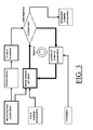
- Figure 1 schematically shows an exemplary system arranged for performing the method according to the invention, comprising a measurement parameters module (MPM) for setting measurement parameters, e.g. the characteristics of the US transducer (like its frequency range, amplitude and phase spectrum, its position and orientation), a Fourier transform module (FTM) for performing a Fourier transform of the reflected signal, as well as a model based simulator (MBS), i.e. a module for outputting artificial, Fourier transformed, reflection signals under control of iteratively variable material (thickness) parameters.
- An initial material parameters module (IMPM) comprises a-priori information such as material parameters like C p (longitudinal speed of sound) and ⁇ (mass density).
- a constraints parameter module (CPM) is provided for setting boundary conditions such as probable thickness and maximum thickness of each layer.
- this method for measuring the thickness of a number of parallel layers is performed as follows.
- a US transducer set by the "Measurement parameters module" emits an ultrasonic signal towards the relevant layers and picks up the reflection signal(s).
- the reflected signal is converted into in the frequency domain by means of a Fourier or Fourier related transform (e.g. Mellin, Laplace, Hartley, Chirplet transform, see http://en.wikipedia.org/wiki/List_of_Fourier-related_transforms).
- an artificial reflection signal is generated (by the "Model based simulator module") using an ultrasonic behaviour model of the parallel layers valid for the relevant ultrasonic signal (set by the “Measurement parameters module”) and for different thickness values of the parallel layers (set by/via the “Initial material parameters module”).
- Matching in an iterative process, a (e.g. Fourier transformed) representation of the (real) reflection signal and a representation of the artificial reflection signal one another, and determining, by iteratively varying in the ultrasonic behaviour model, the thickness values of the parallel layers at which both reflection signals match best.
- This matching process is performed in the loop formed by the three modules "Model based simulator”, “Comparison”, “Update of material parameters” (preferably between some previously set practical/feasible constraints, set in the "Constraints module”).
- the material parameters particularly the thicknesses of the layers (see figure 2 ) for which the (representation of the) real reflection signal and the (representation of the) artificial reflection signal match best is output as the real material parameters, particularly the thicknesses of the layers.
- Transmission is represented by T, Reflection by R and the wave propagation by W.
- the indices represent the different media.
- the W exp(- jkd ), describes the propagation inside a layer.
- d is the layer thickness
- k is the wave number
- k 2 ⁇ ⁇ f c
- c is the complex speed of sound and f the used frequency.
- the total response can be constructed from a number of multiples:
- P total P 0 ⁇ W 1 2 T 12 ⁇ T 21 ⁇ W 2 2 ⁇ R 23 + T 23 ⁇ T 32 ⁇ W 3 2 ⁇ R 34 1 - R 34 ⁇ W 3 2 ⁇ R 32 ⁇ 1 - R 34 ⁇ W 3 2 ⁇ R 32 ( 1 - R 34 ⁇ W 3 2 ⁇ R 32 - W 2 2 ⁇ R 21 ⁇ R 23 - R 34 ⁇ W 3 2 ⁇ R 32 ⁇ R 23 + T 23 ⁇ T 32 ⁇ W 3 2 ⁇ R 34
- P total P 0 ⁇ W 1 2 [ R 123 + T 12 ⁇ T 32 ⁇ W 2 2 [ R 23 - R 23 ⁇ W 3 2 ⁇ R 32 + T 23 ⁇ T 23 ⁇ W 3 2 ⁇ R 34 1 - R 34 ⁇ W 3 2 ⁇ R 32 - R 23 ⁇ W 2 2 ⁇ R 21 - R 34 ⁇ W 3 2 ⁇ R 32 ⁇ R 23 ⁇ W 2 2 ⁇ R 21 + T 23 ⁇ T 32 ⁇ W 3 2 ⁇ R 34 ⁇ W 2 2 ⁇ R 21
- this model can easily be extended to additional layers, for instance an air bubble or water film between a two layered material, or a sandwich construction such as Glare.
- Determination of the medium parameters is done by non-linear curve fitting in the frequency domain. This means that the measured response is compared to equation 10. It must be noticed that the amplitude of all parameters except P 0 is less then or to 1. Depending on the application, some parameters are dominant. These dominant parameters in combination with a Taylor expansion of equation 10 allow us to extract a first guess for the non-linear curve fitting. For instance if a steel layer with a thin protection payer is measured, only R23 R32, R34 and W are dominant.
- This method allows to robustly determine all medium parameters such as speed of sound, thickness, density and attenuation.
- the model can also be extended to multiple layers.
Landscapes
- Physics & Mathematics (AREA)
- General Physics & Mathematics (AREA)
- Investigating Or Analyzing Materials By The Use Of Ultrasonic Waves (AREA)
Abstract
Method for measuring the thickness of a number of parallel layers, the method comprising emitting an ultrasonic signal to the layers and picking up the reflection signal and providing a realistic artificial reflection signal using an ultrasonic behaviour model of the parallel layers valid for the relevant ultrasonic signal and for different thickness values of the parallel layers. Matching, in an iterative process, a representation of the reflection signal and a representation of the artificial reflection signal one another, and determining, by iteratively varying in the ultrasonic behaviour model, the thickness values of the parallel layers at which both reflection signals match best, result into the layer thicknesses to be measured.
Description
- The present invention refers to a method for measuring the thickness of a number of parallel layers, especially, however not exclusively, layers which e.g. are formed by the walls of a steel-concrete pipe e.g. in use in the area of public water supply systems etc., as well as layers formed by deposit layers in e.g. steel oil pipes.
- Due to the high attenuation, e.g. of concrete, deposit etc., present ultrasonic inspection systems are not able to measure both the thickness of the steel and the thickness of the concrete or deposit layer. In general, these layers show frequency dependent attenuation. High frequent systems experience too much attenuation. Low frequent measuring systems, however, are not able to perform the required accuracy. When measuring one material layer, using a low or high frequency source, Fourier transformation of the reflected signals could be a solution. The distance between two successive notches corresponds to the travel time. With the speed of sound inside the layer the thickness can be determined. However, applied to an object having more than one wall, the Fourier figure is non-discriminative as well and the measurement will not be very accurate.
- One aim of the present invention is to use a low frequent broadband ultrasonic measuring technique in such way that accurate measuring results will be achieved in more wall systems as well.
- The invention is based on the use of interferometry and a model based on inversion techniques, permitting to determine the thickness of the two layers. Also aspects as adhesion between both layers, possible coatings, variations in the propagation velocity and mass density of the concrete etc. may be considered.
- According to the invention, in a method for measuring the thickness of a number of parallel layers, next steps are preferred:
- emitting an ultrasonic signal to the layers and picking up the reflection signal;
- providing an artificial reflection signal using an ultrasonic behaviour model of the parallel layers valid for the relevant ultrasonic signal and for different thickness values of the parallel layers;
- matching, in an iterative process, a representation of the reflection signal and a representation of the artificial reflection signal one another, and determining, by iteratively varying in the ultrasonic behaviour model, the thickness values of the parallel layers at which both reflection signals match best.
- It is preferred that both the reflection signal and the artificial reflection signal are represented in the frequency domain.
-
- Figures 1a and 1b
- schematically show an ultrasonic (US) source, two layers the thickness of which has to be measured, and the relevant signal reflections;
- Figure 2
- schematically shows an ultrasonic (US) source, three layers the thickness of which has to be measured, one being sound absorbing, and the relevant signal reflections;
- Figure 3
- schematically shows an exemplary system arranged for performing the method according to the invention.
-
Figure 1a shows an ultrasound transducer sending a pulse which is reflected at each material transition, resulting in a train of rather discriminative reflection pulses p1, p2, p3 etc., if (as infigure 1a ) layers are non or only weakly sound absorbing. From the time intervals p1, p2 etc. between the echoes, and the sound speeds in the relevant layers (indicated as Materials X, Y, Z respectively) the layer thicknesses can be calculated. On the contrary, as illustrated infigure 1b , in pulse-echo measurements applied to a sound absorbing (attenuating) layer X the echoes may thus be weakened that the layer thicknesses can not be measured very well due to a reflection signal in which pulses p1, p2 etc. can hardly or not be discriminated. -
Figure 2 shows, in accordance with the method according to the invention, that the ultrasound transducer sends a broad-band, low-frequency pulse. The reflections result in a signal with a complex interference pattern, which depends on characteristics of the send pulse and the reflecting layers (thicknesses and material properties). Due to the low frequency of the pulse, no discriminative pulses can be found in the reflection signal. Fourier transform of the measurement signal is used to determine the characteristics of the reflecting layered structure. -
Figure 1 schematically shows an exemplary system arranged for performing the method according to the invention, comprising a measurement parameters module (MPM) for setting measurement parameters, e.g. the characteristics of the US transducer (like its frequency range, amplitude and phase spectrum, its position and orientation), a Fourier transform module (FTM) for performing a Fourier transform of the reflected signal, as well as a model based simulator (MBS), i.e. a module for outputting artificial, Fourier transformed, reflection signals under control of iteratively variable material (thickness) parameters. An initial material parameters module (IMPM) comprises a-priori information such as material parameters like Cp (longitudinal speed of sound) and ρ (mass density). A constraints parameter module (CPM) is provided for setting boundary conditions such as probable thickness and maximum thickness of each layer. - Referring to the method according to the present invention as defined in the preceding and illustrated in
figures 2 (signals) and 3 (exemplary system configuration) this method for measuring the thickness of a number of parallel layers, is performed as follows. - As illustrated in
figure 2 (whole) and infigure 3 (the three upper modules), a US transducer, set by the "Measurement parameters module", emits an ultrasonic signal towards the relevant layers and picks up the reflection signal(s). Preferably the reflected signal is converted into in the frequency domain by means of a Fourier or Fourier related transform (e.g. Mellin, Laplace, Hartley, Chirplet transform, see http://en.wikipedia.org/wiki/List_of_Fourier-related_transforms). - As illustrated in
figure 3 , an artificial reflection signal is generated (by the "Model based simulator module") using an ultrasonic behaviour model of the parallel layers valid for the relevant ultrasonic signal (set by the "Measurement parameters module") and for different thickness values of the parallel layers (set by/via the "Initial material parameters module"). - Matching, in an iterative process, a (e.g. Fourier transformed) representation of the (real) reflection signal and a representation of the artificial reflection signal one another, and determining, by iteratively varying in the ultrasonic behaviour model, the thickness values of the parallel layers at which both reflection signals match best. This matching process is performed in the loop formed by the three modules "Model based simulator", "Comparison", "Update of material parameters" (preferably between some previously set practical/feasible constraints, set in the "Constraints module"). The material parameters, particularly the thicknesses of the layers (see
figure 2 ) for which the (representation of the) real reflection signal and the (representation of the) artificial reflection signal match best is output as the real material parameters, particularly the thicknesses of the layers. - In this way several artificial, Fourier transformed, reflection signals are generated under control of iteratively variable material (thickness) parameters, which are compared with the measured reflection signals. An iterative minimization algorithm, such as the Levenberg-Marquardt algorithm, is used to find the actual material parameters, which are output to the "Measured material parameters module" in
figure 3 . - At boundaries from e.g. water or another fluid of gaseous medium - material X and from material X and material Y reflection and transmission occur. This is caused by different acoustical material properties. In the materials itself the acoustic wave propagates with the speed of sound.
- Transmission is represented by T, Reflection by R and the wave propagation by W. The indices represent the different media.
- The W = exp(-jkd), describes the propagation inside a layer. Here d is the layer thickness and k is the wave number

- The expression for the propagation W can also be interpreted by a time delay

- With the representation the measured signal from the reflection from the wave field from the water-X transition measured by an ultrasonic transducer is then given by

where W 1 represents the propagation from the transducer to the transition and back and R 12 the reflection of the wave field at this transition. P 0 represents the emitted acoustic pressure of the transducer. - The measured signal of the direct wave from the reflected wave field caused by the transition from X to Y transition measured by an ultrasonic transducer is given by

When two ore more transitions are involved, multiple reflections occurs - For a single layer, the total response can be constructed from a number of multiples:
- Signal from 1st transition Pfrontwall = P 0 W 1 R 12 W 1
- Signal from 2nd transition P backwall = P 0 W 1 T 12 W 2 R 23 W 2 T 21 W 1
- Signal from the 1st internal multiple P multiple1 = P 0 W 1 T 12 W 2 R 23 W 2 R 21 W 2 R 23 W 2 T 21 W 1
- Signal from the 2nd internal multiple P multiple2 = P 0 W 1 T 12 W 2 R 23 W 2 R 21 W 2 R 23 W 2 R 21 W 2 R 23 W 2 T 21 W 1
And so on. - Combining all individual terms and rewriting results in the total measured signal

- The term inside the brackets can be interpreted as a Taylor expansion

where α = R 23 W 2 2 R 21 represents a single multiple inside the layer. With this Taylor expansion the equation can be simplified to:
- Two layers
When two layers are used instead of one, the situation will become more complex.
The best way to describe multiple layers is to define the reflection layer as a combination as described by the equation above without the propagation in medium1.
- Combining equation 5 and 6 results in:

- Rewriting results in:

- And finally:

- As can be seen in equation 7, this model can easily be extended to additional layers, for instance an air bubble or water film between a two layered material, or a sandwich construction such as Glare.
- Attenuation inside the medium can be easily be realized by generating a complex speed of sound inside the propagation operators W 1 ,W 2 ,W 4 :
Wi = exp(-jkd), where d is the layer thickness and k is the wave number
- Determination of the medium parameters is done by non-linear curve fitting in the frequency domain. This means that the measured response is compared to equation 10.
It must be noticed that the amplitude of all parameters except P 0 is less then or to 1.
Depending on the application, some parameters are dominant. These dominant parameters in combination with a Taylor expansion of equation 10 allow us to extract a first guess for the non-linear curve fitting. For instance if a steel layer with a thin protection payer is measured, only R23 R32, R34 and W are dominant. The measurement response can then be approximated by:
- Meaning the response of the front and back wall of the steel layer and the first internal echo inside the steel layer.
- Currently most system only focus on the extraction of the time delay between the primary or, when measurable also the multiples as is indicated in
figure 1 . This means that most, if not all, systems will only determine W2 and W3. - This method allows to robustly determine all medium parameters such as speed of sound, thickness, density and attenuation. The model can also be extended to multiple layers.
Claims (4)
- Method for measuring the thickness of a number of parallel layers, the method comprising:- emitting an ultrasonic signal to the layers and picking up the reflection signal;- providing an artificial reflection signal using an ultrasonic behaviour model of the parallel layers valid for the relevant ultrasonic signal and for different thickness values of the parallel layers;- matching, in an iterative process, a representation of the reflection signal and a representation of the artificial reflection signal one another, and determining, by iteratively varying in the ultrasonic behaviour model, the thickness values of the parallel layers at which both reflection signals match best.
- Method according to claim 1, the reflection signal as well as the artificial reflection signal being represented in the frequency domain.
- System for performing the method according to claim 1 or 2.
- Software program means for performing or controlling a method according to claim 1 or 2.
Priority Applications (1)
| Application Number | Priority Date | Filing Date | Title |
|---|---|---|---|
| EP07123501A EP2072948A1 (en) | 2007-12-18 | 2007-12-18 | Measuring the thickness of a number of parallel layers |
Applications Claiming Priority (1)
| Application Number | Priority Date | Filing Date | Title |
|---|---|---|---|
| EP07123501A EP2072948A1 (en) | 2007-12-18 | 2007-12-18 | Measuring the thickness of a number of parallel layers |
Publications (1)
| Publication Number | Publication Date |
|---|---|
| EP2072948A1 true EP2072948A1 (en) | 2009-06-24 |
Family
ID=39468292
Family Applications (1)
| Application Number | Title | Priority Date | Filing Date |
|---|---|---|---|
| EP07123501A Withdrawn EP2072948A1 (en) | 2007-12-18 | 2007-12-18 | Measuring the thickness of a number of parallel layers |
Country Status (1)
| Country | Link |
|---|---|
| EP (1) | EP2072948A1 (en) |
Cited By (2)
| Publication number | Priority date | Publication date | Assignee | Title |
|---|---|---|---|---|
| EP2410769A1 (en) * | 2010-07-23 | 2012-01-25 | Sony Ericsson Mobile Communications AB | Method for determining an acoustic property of an environment |
| CN120195686A (en) * | 2025-05-08 | 2025-06-24 | 广东省建设工程质量安全检测总站有限公司 | Automatic measurement method and device for material size |
Citations (3)
| Publication number | Priority date | Publication date | Assignee | Title |
|---|---|---|---|---|
| WO1998003044A1 (en) * | 1996-07-15 | 1998-01-22 | Koninklijke Philips Electronics N.V. | Method and device for measuring the thickness of opaque and transparent films |
| US6397680B1 (en) * | 2000-07-24 | 2002-06-04 | National Research Council Of Canada | Ultrasonic spectroscopy apparatus for determining thickness and other properties of multilayer structures |
| US20030101007A1 (en) * | 2001-11-26 | 2003-05-29 | Lockheed Martin Corporation | Method to characterize material using mathematical propagation models and ultrasonic signal |
-
2007
- 2007-12-18 EP EP07123501A patent/EP2072948A1/en not_active Withdrawn
Patent Citations (3)
| Publication number | Priority date | Publication date | Assignee | Title |
|---|---|---|---|---|
| WO1998003044A1 (en) * | 1996-07-15 | 1998-01-22 | Koninklijke Philips Electronics N.V. | Method and device for measuring the thickness of opaque and transparent films |
| US6397680B1 (en) * | 2000-07-24 | 2002-06-04 | National Research Council Of Canada | Ultrasonic spectroscopy apparatus for determining thickness and other properties of multilayer structures |
| US20030101007A1 (en) * | 2001-11-26 | 2003-05-29 | Lockheed Martin Corporation | Method to characterize material using mathematical propagation models and ultrasonic signal |
Cited By (4)
| Publication number | Priority date | Publication date | Assignee | Title |
|---|---|---|---|---|
| EP2410769A1 (en) * | 2010-07-23 | 2012-01-25 | Sony Ericsson Mobile Communications AB | Method for determining an acoustic property of an environment |
| US8885442B2 (en) | 2010-07-23 | 2014-11-11 | Sony Corporation | Method for determining an acoustic property of an environment |
| CN120195686A (en) * | 2025-05-08 | 2025-06-24 | 广东省建设工程质量安全检测总站有限公司 | Automatic measurement method and device for material size |
| CN120195686B (en) * | 2025-05-08 | 2025-11-18 | 广东省建设工程质量安全检测总站有限公司 | An automatic material dimension measurement method and device |
Similar Documents
| Publication | Publication Date | Title |
|---|---|---|
| US6182512B1 (en) | Method and apparatus for imaging thin structures | |
| CN101632002B (en) | Ultrasonic surface monitoring | |
| US8770027B2 (en) | Pulse-echo method by means of an array-type probe and temperature compensation | |
| EA028919B1 (en) | Method and system for continuous remote monitoring of the integrity of pressurized pipelines and properties of the fluids transported | |
| JP2017525948A (en) | Signal propagation time difference type flow meter | |
| CN105102924A (en) | Ultrasonic detection of changes in wall surface | |
| WO2003078996A1 (en) | Self calibrating apparatus and method for ultrasonic determination of fluid properties | |
| Stepinski | Novel instrument for inspecting rock bolt integrity using ultrasonic guided waves | |
| CN103926581B (en) | A kind of measuring method of sonar target echo bright spot parameter | |
| US20110239768A1 (en) | Pulse-echo method for determining the damping block geometry | |
| Messineo et al. | Layered material characterization using ultrasonic transmission. An inverse estimation methodology | |
| CN106841385B (en) | Detection method of powder adhesion state of polypropylene production pipeline based on acoustic-ultrasonic | |
| CN121476072A (en) | Film measurement methods, computer-readable storage media | |
| JP2008070388A (en) | Method and apparatus for detecting liquid level by sound | |
| RU2451931C1 (en) | Method for ultrasonic inspection of articles with acoustic surface waves | |
| EP3100042B1 (en) | DEVICE AND METHOD FOR NON-DESTRUCTIVE TESTING OF A TEST PERSON USING ULTRASOUND ACCORDING TO DGS METHOD | |
| RU2714868C1 (en) | Method of detecting pitting corrosion | |
| RU2540942C1 (en) | Method to monitor dynamics of variation of controlled object wall thickness | |
| Malekshahi et al. | A solution to the wave equation to model a photo-acoustic imaging system underwater | |
| WO2010053136A1 (en) | Object probing device, object probing program, and object probing method | |
| Lemlikchi et al. | Parametric estimation of overlapping echoes reflected from coated media | |
| Klieber et al. | Mapping of ultrasonic Lamb-wave field in elastic layered structures using laser probes | |
| Havugarurema et al. | Damage detection in concrete using synthetic aperture focusing technique | |
| US10444201B2 (en) | Method of determining the magnitude of a field variable of an energy wave | |
| Rupitsch et al. | Efficient numerical simulation of transducer outputs for acoustic microscopes |
Legal Events
| Date | Code | Title | Description |
|---|---|---|---|
| PUAI | Public reference made under article 153(3) epc to a published international application that has entered the european phase |
Free format text: ORIGINAL CODE: 0009012 |
|
| AK | Designated contracting states |
Kind code of ref document: A1 Designated state(s): AT BE BG CH CY CZ DE DK EE ES FI FR GB GR HU IE IS IT LI LT LU LV MC MT NL PL PT RO SE SI SK TR |
|
| AX | Request for extension of the european patent |
Extension state: AL BA HR MK RS |
|
| AKX | Designation fees paid | ||
| REG | Reference to a national code |
Ref country code: DE Ref legal event code: 8566 |
|
| STAA | Information on the status of an ep patent application or granted ep patent |
Free format text: STATUS: THE APPLICATION IS DEEMED TO BE WITHDRAWN |
|
| 18D | Application deemed to be withdrawn |
Effective date: 20091229 |