EP2072895A1 - Gas burner with improved primary air duct - Google Patents
Gas burner with improved primary air duct Download PDFInfo
- Publication number
- EP2072895A1 EP2072895A1 EP07123470A EP07123470A EP2072895A1 EP 2072895 A1 EP2072895 A1 EP 2072895A1 EP 07123470 A EP07123470 A EP 07123470A EP 07123470 A EP07123470 A EP 07123470A EP 2072895 A1 EP2072895 A1 EP 2072895A1
- Authority
- EP
- European Patent Office
- Prior art keywords
- conduit
- gas
- primary air
- venturi pipe
- gas burner
- Prior art date
- Legal status (The legal status is an assumption and is not a legal conclusion. Google has not performed a legal analysis and makes no representation as to the accuracy of the status listed.)
- Granted
Links
Images





Classifications
-
- F—MECHANICAL ENGINEERING; LIGHTING; HEATING; WEAPONS; BLASTING
- F23—COMBUSTION APPARATUS; COMBUSTION PROCESSES
- F23D—BURNERS
- F23D14/00—Burners for combustion of a gas, e.g. of a gas stored under pressure as a liquid
- F23D14/02—Premix gas burners, i.e. in which gaseous fuel is mixed with combustion air upstream of the combustion zone
- F23D14/04—Premix gas burners, i.e. in which gaseous fuel is mixed with combustion air upstream of the combustion zone induction type, e.g. Bunsen burner
- F23D14/06—Premix gas burners, i.e. in which gaseous fuel is mixed with combustion air upstream of the combustion zone induction type, e.g. Bunsen burner with radial outlets at the burner head
-
- F—MECHANICAL ENGINEERING; LIGHTING; HEATING; WEAPONS; BLASTING
- F23—COMBUSTION APPARATUS; COMBUSTION PROCESSES
- F23D—BURNERS
- F23D14/00—Burners for combustion of a gas, e.g. of a gas stored under pressure as a liquid
- F23D14/46—Details
- F23D14/62—Mixing devices; Mixing tubes
- F23D14/64—Mixing devices; Mixing tubes with injectors
-
- F—MECHANICAL ENGINEERING; LIGHTING; HEATING; WEAPONS; BLASTING
- F23—COMBUSTION APPARATUS; COMBUSTION PROCESSES
- F23D—BURNERS
- F23D2900/00—Special features of, or arrangements for burners using fluid fuels or solid fuels suspended in a carrier gas
- F23D2900/14—Special features of gas burners
- F23D2900/14062—Special features of gas burners for cooking ranges having multiple flame rings
-
- F—MECHANICAL ENGINEERING; LIGHTING; HEATING; WEAPONS; BLASTING
- F23—COMBUSTION APPARATUS; COMBUSTION PROCESSES
- F23D—BURNERS
- F23D2900/00—Special features of, or arrangements for burners using fluid fuels or solid fuels suspended in a carrier gas
- F23D2900/14—Special features of gas burners
- F23D2900/14701—Swirling means inside the mixing tube or chamber to improve premixing
Definitions
- the present invention relates to a gas burner, preferably of the type generally used in the household cooking gas appliances and in particular gas built-in hobs, provided with improved means to convey the primary air into the Venturi pipe.
- a cooking appliance according to the invention comprises:
- the primary air is being conveyed towards said nozzle 5 and into said Venturi pipe through two different flowing paths, i.e.:
- Said through opening 8 then allows the primary air flow to pass from the outer room towards said Venturi pipe 4, so achieving the first invention goal, i.e. to make the primary air to intake by splitting the whole flow into two separate flows, one of which being arranged over said upper plane 12, and the other being conveyed from the inside of the cooking appliance and which in its end path enters into a conduit which is coaxial to the gas conduit.
- the first improvement consists in that, as shown in figures 3 and 4 , said coaxial conduit 6 draws the relevant primary air flow directly from the inner volume delimited by the box body 34 of the cooking appliance, while instead said opening 8 is connected to the outer room, and exactly from over its top surface.
- said opening 8 is placed upwards in said prolongation 9, so as to shorten and to make straighter the path of that share of primary air flow coming from over the cooking appliance.
- the shown embodiments may be implemented by a gas conduit and a Venturi pipe which are horizontally oriented, as represented in the figures 2 , 3 and 4 ; however, as previously remembered, it is also possible to make up the invention by placing the gas conduit and the relevant Venturi pipe vertically oriented, as schematically shown in fig. 7 .
- the outlet mouth of the conduit 6 is completely opened, and so the air path, coming from the outside and sucked into the channel 13, crosses an opening 20 showing a substantially cylindrical or frustum-conical shape, extended on the horizontal plane for 360°, and connecting the outlet mouth 6A of the coaxial conduit to the inlet mouth 4B of the Venturi pipe 4.
- said same upper plane 12 makes also the lower side of the channel 13 through which the primary air is sucked into said second path and is conveyed into said opening 8.
- said inlet 14 of said channel 13 is then opened just over said upper plane 12; moreover, in correspondence of said mouth 14 said surface 12 takes a profile in relief 15, so as the incidental liquids and cooking remnants are prevented from entering said channel 13; advantageously said relief profile 15 may easily be obtained by a proper pressing /bending operation of this same upper plane 12.
Landscapes
- Engineering & Computer Science (AREA)
- Chemical & Material Sciences (AREA)
- Combustion & Propulsion (AREA)
- Mechanical Engineering (AREA)
- General Engineering & Computer Science (AREA)
- Gas Burners (AREA)
Abstract
The coaxial conduit draws the respective air flow from a zone inside the body of said cooking appliance, and said opening allows the passage of the respective primary air flow sucked and coming from over the appliance top surface (12). In order to stir the primary air flow passing through said coaxial conduit, a plurality of radial wings (10A) is arranged, said wings being shaped either planar or helical, and being connected on the outer surface of said gas supply conduit.
Description
- The present invention relates to a gas burner, preferably of the type generally used in the household cooking gas appliances and in particular gas built-in hobs, provided with improved means to convey the primary air into the Venturi pipe.
- In the following of this description it will be referred to a gas burner provided with both a central body with a peripheral flame crown, and a perimetral body provided with two flame crowns, oriented inwards and outwards, but it will be intended that what explained may be identically applied and therefore valid also for gas burners provided with only a peripheral body, that is without the central flame body.
- It is known that in such kind of cooking gas appliance two main requirements are present:
- a constructional and assembly requirement, i.e. the cooking gas appliance, particularly when it is a gas hob, has to show a minimum height, due to constraints which are well known to the man skilled in the art, and therefore will not be repeated, and
- a functional requirement, consisting in that the burner, specially those burners with limited diameter, are requested to provide in any case a suitable thermal power, and in any case the maximum possible power.
- These two requirements are however in apparent contradiction to each other, as the need to keep down the total gas appliance height obliges to also keep down the same height of the Venturi pipes providing the gas to the burners; however such limitation operates also as a limitation for the amount of gas/air mixture which can be produced, and therefore determines the limit of the burner thermal power.
- In order to overcome such reciprocal conditioning, some cooking appliances have been proposed and divulged, which are provided with one ore more Venturi pipes which are horizontally extended as for instance in the patents
WO 2005/078342 andWO 2007/012766 . - It is apparent that by horizontally placing the Venturi pipes, it is automatically void the problem of their height which conditions the overall height of the cooking appliance.
- Moreover the two cited patents show respective solutions wherein the Venturi pipes leave from the burner central zone and branch out radially; therefore their total length is limited by the radius, that is by the horizontal size of the burner itself.
- In order to eliminate such condition it was proposed, for instance in
EP Publication 1120603 and inEP Application n. 07119078.9 - However the showed solutions suffer from a quite common drawback in such type of burners, that is from the fact that the primary air is sucked and sent to the inlet of the Venturi pipe from one access way only, i.e. either from the inner box body of the cooking appliance, or from the outer room, that is from the zone over the cooking hob itself.
- Of course such circumstance does limit the total amount of the available primary air, and therefore limits the available thermal power.
- In order to increase the primary air inlet flow, it was proposed to intake and convey the primary air flow through a coaxial and preferably tubular conduit, the final portion of which ending with the gas injection nozzle.
- Such solution is for instance divulged in the patents:
- a)
-
US 2006/0199119 , - b)
-
US 6,951,454 , - c)
-
JP 3-244906 - d)
-
JP 3-244905 - e)
-
US 2005/0279862 . - However no one of said patents suggest, and even less divulgates, the solution which shows that the primary air flow, bound to the Venturi pipe, is taken from two distinct access ways, that is from a conduit which is coaxial to the gas conduit, and also from an opening which is independent of said coaxial conduit.
- It would therefore be desirable, and is actually a main purpose of the present invention, to implement a kind of burner provided with two different and distinct inlet ways for the primary air flows to the Venturi pipe made up by a conduit which is coaxial to the gas conduit, and by an opening or gate placed just after the gas injection nozzle, wherein said access ways are independently flown with air taken from the inside of the box body of the cooking appliance , and from the outer room over it.
- However such purpose turns to be profitable not only with gas conduits and related Venturi pipes when horizontally oriented, where the benefits are more apparent, but also with cooking appliances provided with gas conduits and Venturi pipes which are vertically oriented, even if some drawbacks may be experienced caused by the height of the cooking appliance, yet the same the same benefits due to a double primary air suction are achieved, i.e. from the inside of the cooking appliance body, and from the outer room over it.
- According to the present invention, this and further aims are reached in a kind of burner provided with a Venturi pipe which can be either horizontally or vertically extended, which is provided with connecting and inlet conduits for the primary air flow incorporating the characteristics as recited in the appended claims and including such operating means as described below by mere way of non-limiting example with reference to the accompanying drawings, in which:
-
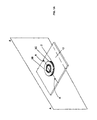
Fig. 1 is a perspective outer view of a burner body and of the relevant cooking gas appliance, here represented by a gas hob, according to a first embodiment of the invention, -
Fig. 2 is an exploded view of the cooking burner shown infig. 1 , -
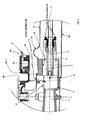
Fig. 3 shows a vertical and side section view according to the section A - A of the assembly offig. 1 , -
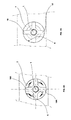
Fig. 3A shows a section view, which is orthogonal to the "X" axis of the gas conduit, of a detail of the burner assembly offig. 3 , -
Fig. 4 shows a vertical and side section view according to the section A - A of a different embodiment of the assembly offig. 1 , -
Fig. 4A shows a section view, which is orthogonal to the "X" axis of the gas conduit, of a detail of the burner assembly offig. 4 , -
Figures 5 and6 do show perspective views of the details respectively shown infigures 3A and 4A , -
Fig. 7 shows a view which is equivalent tofig. 3 , but referred to a cooking appliance provided with a gas conduit and a Venturi pipe which are vertically oriented. - With reference to
figures 1 to 4 , a cooking appliance according to the invention comprises: - a
gas supply conduit 1 horizontally oriented, - a
burner body 2 on which one ormore flame crowns - a Venturi
pipe 4 which is also extended into horizontal, and is substantially aligned with the final portion of saidconduit 1, - an
gas injection nozzle 5 at the end of saidconduit 1 towards said Venturipipe 4. - The primary air is being conveyed towards said
nozzle 5 and into said Venturi pipe through two different flowing paths, i.e.: - the first path consists of a suction air flow beginning from inside the body of the cooking appliance, and which in its end portion takes the form of a
conduit 6 coaxial with saidfirst gas conduit 1, having a preferably tubular shape, and which surrounds it at least in the end portion; therefore between saidgas conduit 1 and said coaxial conduit 6 a prolongedannular interspace 7 is formed, in which flows a share of the primary air, sucked by the Venturi pipe.
As clearly shown in the figures, saidcoaxial conduit 6 stretches towards said Venturipipe 4, to which it joins through asuitable prolongation 9; as a matter of facts, it may be observed that the Venturi pipe is merely the properly shaped continuation of saidprolongation 9, which to its time stretches ahead beyond saidinjector 5; - the second path consists of a
channel 13 whose suction mouth opens over of theupper plane 12, and in its end portion a through opening 8 is arranged, preferably placed on a side of saidprolongation 9, just downstream of saidinjector 5 and upstream of said Venturipipe 4. - Said through opening 8 then allows the primary air flow to pass from the outer room towards said Venturi
pipe 4, so achieving the first invention goal, i.e. to make the primary air to intake by splitting the whole flow into two separate flows, one of which being arranged over saidupper plane 12, and the other being conveyed from the inside of the cooking appliance and which in its end path enters into a conduit which is coaxial to the gas conduit. - The just described solution allows some profitable improvements; the first improvement consists in that, as shown in
figures 3 and4 , saidcoaxial conduit 6 draws the relevant primary air flow directly from the inner volume delimited by thebox body 34 of the cooking appliance, while instead said opening 8 is connected to the outer room, and exactly from over its top surface. - This circumstance favors a better air flowing in the case that the cooking appliance is undesirably lodged in such a way that the air circulation is obstructed or slowed down; moreover the two primary air flows, so conveyed, do not interfere in any working condition.
- Also it is preferred that said opening 8 is placed upwards in said
prolongation 9, so as to shorten and to make straighter the path of that share of primary air flow coming from over the cooking appliance. - Such solution is suitable to match the temperature increase; since the heating from the burner reduces the density of the primary air, it is important to improve the primary air flow, in order to avoid compromising the burner functionality (combustion performances, yellow tipping and soot).
- In order to improve the mixing of the gas with the primary air, it was experienced as an useful improvement to arrange some means able of causing a turbulence in gas flow when coming out from the
conduit 1, so that the gas flow itself is being broken and therefore it is easier mixed with the primary air flow. - It was then found profitable to arrange some suitable means able of creating a turbolence in the air passing through said
interspace 7, so that the air going out from it, and basically from saidcoaxial conduit 6, is soon mixed both to the gas exiting from theconduit 1, and to the primary air flow entering from said opening 8. - Such complete and prompt mixing effect both with the gas and with the primary air flow obviously causes the mixture itself to become optimized, what improves the combustion performances.
- To this purpose, inside said
interspace 7 and on theouter surface 11 of said gas conduit some stirringwings 10 are arranged; according to the turbulence effect which is wanted, and also to the diameter of thecoaxial conduit 6 itself, the two following embodiments are proposed: - in the first embodiment and with ref. to the
figures 4 and4A , saidwings 10 are flat, are preferably passing on the "X" axis of saidgas conduit 1, are radially oriented on the outer surface of thegas conduit 1, are regularly distributed at the same angular distance to each other, and preferably are quite prolonged so as to be extended for the whole length of saidcoaxial conduit 6. - in the second embodiment and with ref. to
figure 5 and 5A, saidwings 10A are bent and specifically are placed in an helical arrangement, as a screw thread, whose inner edge is still attached on the outer surface of thegas conduit 1; saidwings 10A too are regularly distributed with the same angular distance, and preferably are quite prolonged so as to be extended for the whole length of saidcoaxial conduit 6. - The two just described improved embodiments are obviously helpful to make up a cooking appliance which is particularly effective not only from the point of view of the thermal power supply, but also which is compact and especially cheap and simple in the construction; moreover the invention may be highly appreciated also due to the advantage that the nozzle replacement may be carried out without any need to open the appliance. as this operation may be performed across said opening 8.
- As just described, the shown embodiments may be implemented by a gas conduit and a Venturi pipe which are horizontally oriented, as represented in the
figures 2 ,3 and4 ; however, as previously remembered, it is also possible to make up the invention by placing the gas conduit and the relevant Venturi pipe vertically oriented, as schematically shown infig. 7 . - In said case it has been proved that the most suitable embodiment, both from a functional and a constructive point of view is offered by the
fig. 7 itself, wherein said Venturi pipe is substantially separated from the coaxial conduit 6 (differently fromfig. 3 , wherein said devices are interconnected by said prolongation 9). - Therefore the outlet mouth of the
conduit 6 is completely opened, and so the air path, coming from the outside and sucked into thechannel 13, crosses an opening 20 showing a substantially cylindrical or frustum-conical shape, extended on the horizontal plane for 360°, and connecting theoutlet mouth 6A of the coaxial conduit to the inlet mouth 4B of the Venturipipe 4. - Furthermore, and preferably, said same
upper plane 12 makes also the lower side of thechannel 13 through which the primary air is sucked into said second path and is conveyed into said opening 8. - So the
inlet 14 of saidchannel 13 is then opened just over saidupper plane 12; moreover, in correspondence of saidmouth 14 saidsurface 12 takes a profile inrelief 15, so as the incidental liquids and cooking remnants are prevented from entering saidchannel 13; advantageously saidrelief profile 15 may easily be obtained by a proper pressing /bending operation of this sameupper plane 12.
Claims (14)
- Gas burner for cooking gas appliances, and particularly for household cooking hobs, comprising:- a gas conveying conduit (1), extended on horizontal or on vertical,- means to provide the suction of the primary air flow,- a burner body (2) on which one or more flame crowns (3B, 3C) are mounted,- an horizontal or vertical Venturi pipe (4),- a nozzle (5) apt of injecting the gas flow from said conveying conduit (1) into said Venturi pipe (4),characterized in that said means to provide the suction of the primary air flow do include two different inflow paths:- wherein a first path comprises a coaxial conduit (6), and substantially tubular shaped, to said gas conveying conduit (1), which is lodged inside it forming an prolonged annular interspace (7),- and wherein the second path comprises a through opening (8) made up in the inflow passage of outer air, and arranged in a position downstream said nozzle (5) and upstream the inlet to said Venturi pipe (4).
- Gas burner according to claim 1, characterized in that said coaxial conduit (6) draws the relevant primary air flow from an inner zone of said cooking appliance, and that said opening (8) allows the intake of the respective primary air flow which is sucked and comes from the upper zone of said cooking appliance.
- Gas burner according to claim 2, characterized in that said coaxial conduit (6) and said Venturi pipe are horizontally oriented, and that said coaxial conduit is provided with a prolongation (9) extending ahead and towards said Venturi pipe (4) until substantially joining its inlet mouth, and in that said through opening (8) is arranged in said prolongation (9).
- Gas burner according to claim 3, characterized in that said opening (8) is placed in the upper portion of said prolongation (9).
- Gas burner according to claim 1 or 2, characterized in that suitable means are provided, which are lodged inside said annular interspace (7), able of stirring the primary air flow in said coaxial conduit (6).
- Gas burner according to claim 5, characterized in that said stirring means comprise a plurality of properly shaped wings (10), radially arranged with respect to the axis (X) of said gas conduit (1).
- Gas burner according to claim 5, characterized in that said stirring means comprise a plurality of properly shaped wings (10A), helicoidally arranged with respect to the axis (X) of said gas conduit (1), and on the outer surface (11) of it.
- Gas burner according to claim 6 or 7, characterized in that said wings (10, 10A) are placed on the outer surface (11) of said gas conduit (1).
- Gas burner according to any of the previous claims, characterized in that said coaxial conduit (6) is placed in correspondence to the end portion and around the outer surface (11) of said gas conduit (1).
- Gas burner according to any of claims 1, 2 and 5 to 9, characterized in that said gas conduit (1), said Venturi pipe (4) and said coaxial conduit (6) are vertically oriented and are basically aligned, and that said through opening (8) is made by a cylindrical or frustum-conical opening at 360° having its axis aligned or parallel to the axis of said Venturi pipe (4), and is delimited on one side by the inlet mouth of said Venturi pipe (4), and on the opposite side by said coaxial conduit.
- Cooking appliance, particularly cooking hob, comprising a burner according to one of the previous claims, characterized in that it is provided with an upper plane or surface (12) which partially forms the lower side of the suction inflow channel (13) of said second path and which enters said through opening (8).
- Cooking appliance according to claim 11, characterized in that the inlet mouth (14) of said inflow channel (13) is arranged exactly over said upper surface (12).
- Cooking appliance according to claim 12, characterized in that, in correspondence to said inlet mouth (14), said upper plane (12) is being formed with a relief shape (15).
- Cooking appliance according to claim 13, characterized in that said relief shape (14) is made up with a proper working of said upper plane (12).
Priority Applications (13)
| Application Number | Priority Date | Filing Date | Title |
|---|---|---|---|
| EP07123470.2A EP2072895B1 (en) | 2007-12-18 | 2007-12-18 | Gas burner with improved primary air duct |
| PL07123470T PL2072895T3 (en) | 2007-12-18 | 2007-12-18 | Gas burner with improved primary air duct |
| ES07123470.2T ES2504516T3 (en) | 2007-12-18 | 2007-12-18 | Gas burner with improved main air duct |
| JP2010538552A JP5449188B2 (en) | 2007-12-18 | 2008-12-04 | Gas burner with improved primary air conduit |
| CN2008801188383A CN101883952B (en) | 2007-12-18 | 2008-12-04 | Gas burner with improved primary air duct |
| AU2008337734A AU2008337734B2 (en) | 2007-12-18 | 2008-12-04 | Cooking appliance |
| CA2705691A CA2705691A1 (en) | 2007-12-18 | 2008-12-04 | Gas burner with improved primary air duct |
| KR1020107011691A KR101504791B1 (en) | 2007-12-18 | 2008-12-04 | Gas burner with improved primary air duct |
| US12/745,785 US9909758B2 (en) | 2007-12-18 | 2008-12-04 | Gas burner with improved primary air duct |
| PCT/EP2008/066833 WO2009077348A1 (en) | 2007-12-18 | 2008-12-04 | Gas burner with improved primary air duct |
| RU2010129524/06A RU2438069C1 (en) | 2007-12-18 | 2008-12-04 | Gas burner with improved primary air duct and gas stove containing such burner |
| NZ584906A NZ584906A (en) | 2007-12-18 | 2008-12-04 | Gas burner for cooking applicances with air turbulating means to stir the primary air flow |
| BRPI0820790-9A BRPI0820790A2 (en) | 2007-12-18 | 2008-12-04 | Improved primary air duct gas burners |
Applications Claiming Priority (1)
| Application Number | Priority Date | Filing Date | Title |
|---|---|---|---|
| EP07123470.2A EP2072895B1 (en) | 2007-12-18 | 2007-12-18 | Gas burner with improved primary air duct |
Publications (2)
| Publication Number | Publication Date |
|---|---|
| EP2072895A1 true EP2072895A1 (en) | 2009-06-24 |
| EP2072895B1 EP2072895B1 (en) | 2014-07-23 |
Family
ID=39521808
Family Applications (1)
| Application Number | Title | Priority Date | Filing Date |
|---|---|---|---|
| EP07123470.2A Not-in-force EP2072895B1 (en) | 2007-12-18 | 2007-12-18 | Gas burner with improved primary air duct |
Country Status (13)
| Country | Link |
|---|---|
| US (1) | US9909758B2 (en) |
| EP (1) | EP2072895B1 (en) |
| JP (1) | JP5449188B2 (en) |
| KR (1) | KR101504791B1 (en) |
| CN (1) | CN101883952B (en) |
| AU (1) | AU2008337734B2 (en) |
| BR (1) | BRPI0820790A2 (en) |
| CA (1) | CA2705691A1 (en) |
| ES (1) | ES2504516T3 (en) |
| NZ (1) | NZ584906A (en) |
| PL (1) | PL2072895T3 (en) |
| RU (1) | RU2438069C1 (en) |
| WO (1) | WO2009077348A1 (en) |
Cited By (4)
| Publication number | Priority date | Publication date | Assignee | Title |
|---|---|---|---|---|
| WO2013156902A3 (en) * | 2012-04-20 | 2014-02-06 | BSH Bosch und Siemens Hausgeräte GmbH | Burner for a gas-heated cooking appliance |
| WO2015114600A1 (en) * | 2014-02-03 | 2015-08-06 | BSH Hausgeräte GmbH | Gas burner, cooking zone, and stove |
| EP3012527A1 (en) * | 2014-10-21 | 2016-04-27 | BSH Hausgeräte GmbH | Gas cooking equipment and hotplate |
| EP3980689A4 (en) * | 2019-07-10 | 2023-03-22 | Femas Metal San. Ve Tic. A.S. | BURNER ASSEMBLY WITH IMPROVED VENTURI ELEMENT |
Families Citing this family (16)
| Publication number | Priority date | Publication date | Assignee | Title |
|---|---|---|---|---|
| MX345335B (en) * | 2009-12-18 | 2017-01-25 | Mabe S A De C V * | Triple flame section burner. |
| MX338797B (en) * | 2010-06-30 | 2016-05-02 | Sabaf Spa | Gas burner. |
| USD726898S1 (en) * | 2013-03-13 | 2015-04-14 | John E. Hibbard | Fire lighter |
| CL2013001049A1 (en) * | 2013-04-16 | 2014-12-26 | Cti S A | A gas stove oven burner comprising a venturi and which is formed by a housing, comprises at least one internal projection to the burner located downstream of the venturi and inclined with respect to an internal fluid flow. |
| EP2833060A1 (en) * | 2013-08-01 | 2015-02-04 | ELECTROLUX PROFESSIONAL S.p.A. | Gas burner for a cooktop |
| US9541294B2 (en) | 2013-08-06 | 2017-01-10 | Whirlpool Corporation | Inner swirling flame gas burner |
| US20150107577A1 (en) * | 2013-10-18 | 2015-04-23 | Lg Electronics Inc. | Burner |
| USD745321S1 (en) * | 2014-01-13 | 2015-12-15 | Jürgen Koch | Gas burner |
| CN104713086A (en) * | 2015-03-12 | 2015-06-17 | 广东美的厨房电器制造有限公司 | Burner and gas appliance |
| ES2645299B1 (en) * | 2016-06-03 | 2018-09-12 | Bsh Electrodomésticos España, S.A. | GAS BURNER AND DOMESTIC COOKING APPLIANCE |
| US10436451B2 (en) | 2016-10-06 | 2019-10-08 | Whirlpool Corporation | Cap to change inner flame burner to vertical flame |
| ES2697724B2 (en) * | 2017-07-26 | 2021-05-14 | Copreci S Coop | Gas burner assembly for a gas cooking appliance, and gas cooking appliance incorporating said gas burner assembly |
| ES2702785A1 (en) | 2017-09-05 | 2019-03-05 | Bsh Electrodomesticos Espana Sa | DISPOSAL OF GAS BURNERS AND DOMESTIC COOKING APPARATUS (Machine-translation by Google Translate, not legally binding) |
| US11085645B2 (en) * | 2018-05-31 | 2021-08-10 | Haier Us Appliance Solutions, Inc. | Eductor for a gas cooktop appliance |
| WO2021006829A1 (en) * | 2019-07-10 | 2021-01-14 | Femas Metal San. Ve Tic. A.S. | Burner assembly for a gas cooking device |
| CN110425576B (en) * | 2019-07-26 | 2020-12-25 | 宁波方太厨具有限公司 | Gas kitchen ranges |
Citations (12)
| Publication number | Priority date | Publication date | Assignee | Title |
|---|---|---|---|---|
| FR1043707A (en) | 1951-10-10 | 1953-11-10 | Gerard Becuwe Sa Des Ets | Gas burner capable of operating with all common combustible gases |
| FR1055564A (en) * | 1951-06-09 | 1954-02-19 | Le Reve | Burner for gas stove |
| JPH03244906A (en) | 1990-02-21 | 1991-10-31 | Hitachi Ltd | Coaxial injector for burner |
| JPH03244905A (en) | 1990-02-21 | 1991-10-31 | Hitachi Ltd | Coaxial injector for burner |
| US5567148A (en) | 1994-12-20 | 1996-10-22 | Eaton Corporation | Gaseous fuel burner assembly and method of connecting same |
| EP1120603A2 (en) | 2000-01-28 | 2001-08-01 | Sourdillon | Gas burner with multiple flame rings |
| US6851454B2 (en) | 2002-11-08 | 2005-02-08 | Ring Industrial Group, L.P. | Reinforcing support for plastic pipe |
| WO2005078342A1 (en) | 2004-02-13 | 2005-08-25 | So.M.I. Press-Societa'metalli Iniettati S.P.A. | Double burner for gas cookers, of the type provided with multiple concentric flame crowns |
| US20050279862A1 (en) | 2004-06-09 | 2005-12-22 | Chien-Pei Mao | Conical swirler for fuel injectors and combustor domes and methods of manufacturing the same |
| US20060199119A1 (en) | 2005-03-07 | 2006-09-07 | Gas Technology Institute | Multi-ported, internally recuperated burners for direct flame impingement heating applications |
| WO2007012766A1 (en) | 2005-07-29 | 2007-02-01 | Burner Systems International (Bsi) | Gas burner with multiple concentric flame rings |
| WO2007068659A1 (en) * | 2005-12-15 | 2007-06-21 | Arcelik Anonim Sirketi | A cooking device |
Family Cites Families (29)
| Publication number | Priority date | Publication date | Assignee | Title |
|---|---|---|---|---|
| US1947866A (en) * | 1929-12-26 | 1934-02-20 | John T Mccourt | Gas burner |
| US2335188A (en) * | 1940-08-03 | 1943-11-23 | Kennedy Van Saun Mfg & Eng | Fuel burner |
| US3486834A (en) * | 1968-04-25 | 1969-12-30 | Combustion Eng | Gas burning system arrangement |
| US3792582A (en) * | 1970-10-26 | 1974-02-19 | United Aircraft Corp | Combustion chamber for dissimilar fluids in swirling flow relationship |
| JPS5435378Y2 (en) * | 1971-09-21 | 1979-10-27 | ||
| JPS56158723U (en) * | 1980-04-24 | 1981-11-26 | ||
| JPH0765732B2 (en) * | 1986-01-21 | 1995-07-19 | 清一 中村 | Gas burner |
| JPS62160133U (en) * | 1986-03-31 | 1987-10-12 | ||
| JPH01208608A (en) * | 1988-02-12 | 1989-08-22 | Kitazawa Sangyo Kk | Pressurized combustion type burner utilizing self-restored gas pressure |
| DE3930569C2 (en) * | 1989-09-13 | 1995-06-01 | Siegfried W Schilling | Burner head |
| RU2053448C1 (en) * | 1992-11-16 | 1996-01-27 | Государственный научно-исследовательский и проектный институт азотной промышленности и продуктов органического синтеза | Injector-type incomplete premixing gas burner |
| JP3244905B2 (en) | 1993-12-28 | 2002-01-07 | キヤノン株式会社 | Angular displacement detection device and image blur correction device |
| JP3244906B2 (en) | 1993-12-29 | 2002-01-07 | 日本石油化学株式会社 | Polyolefin garbage bag |
| CA2162244C (en) * | 1994-11-14 | 1999-04-27 | Hideaki Oota | Pulverized coal combustion burner |
| JPH1151316A (en) * | 1997-08-01 | 1999-02-26 | Hitachi Zosen Corp | Combustion burner and combustion method |
| IT1294585B1 (en) * | 1997-08-11 | 1999-04-12 | Defendi Srl Off Mec | GAS BURNER WITH SEVERAL FLAME SECTORS. |
| WO2001044720A1 (en) * | 1999-12-15 | 2001-06-21 | Osaka Gas Co., Ltd. | Fluid distributor, burner device, gas turbine engine, and cogeneration system |
| US6315552B1 (en) * | 2000-03-31 | 2001-11-13 | General Electric Company | Dual fuel circuit gas burner |
| JP2002122309A (en) * | 2000-10-16 | 2002-04-26 | Osaka Gas Co Ltd | Turning pre-mixing burner and heat source machine equipped with former |
| JP2003083516A (en) * | 2001-09-12 | 2003-03-19 | Matsushita Electric Ind Co Ltd | Gas stove burner device |
| ITMI20020315A1 (en) * | 2002-02-18 | 2003-08-18 | Sabaf Spa | HOB IN TEMPERED GLASS OR OTHER THERMALLY DEGRADABLE MATERIAL |
| JP2004019998A (en) * | 2002-06-13 | 2004-01-22 | Shinagawa Kogyosho:Kk | Gas burner |
| US6951454B2 (en) | 2003-05-21 | 2005-10-04 | The Babcock & Wilcox Company | Dual fuel burner for a shortened flame and reduced pollutant emissions |
| ITUD20030137A1 (en) * | 2003-06-23 | 2004-12-24 | Sami Srl | TRIPLE CROWN BURNER. |
| JP4047801B2 (en) | 2003-12-10 | 2008-02-13 | 株式会社 土谷金属 | Gas burner |
| RU44369U1 (en) * | 2004-11-03 | 2005-03-10 | Ижевский государственный технический университет | GAS-BURNER |
| ITVE20050004A1 (en) * | 2005-01-20 | 2006-07-21 | Ohg Defendi S R L | GAS BURNER FOR COOKING EQUIPMENT. |
| ES2719203T3 (en) * | 2007-10-23 | 2019-07-09 | Electrolux Home Products Corp Nv | Enhanced gas burner |
| EP2236921B1 (en) * | 2009-03-18 | 2014-11-05 | Electrolux Home Products Corporation N.V. | Improved gas burner |
-
2007
- 2007-12-18 EP EP07123470.2A patent/EP2072895B1/en not_active Not-in-force
- 2007-12-18 PL PL07123470T patent/PL2072895T3/en unknown
- 2007-12-18 ES ES07123470.2T patent/ES2504516T3/en active Active
-
2008
- 2008-12-04 JP JP2010538552A patent/JP5449188B2/en not_active Expired - Fee Related
- 2008-12-04 BR BRPI0820790-9A patent/BRPI0820790A2/en active Search and Examination
- 2008-12-04 CN CN2008801188383A patent/CN101883952B/en not_active Expired - Fee Related
- 2008-12-04 US US12/745,785 patent/US9909758B2/en not_active Expired - Fee Related
- 2008-12-04 WO PCT/EP2008/066833 patent/WO2009077348A1/en not_active Ceased
- 2008-12-04 KR KR1020107011691A patent/KR101504791B1/en not_active Expired - Fee Related
- 2008-12-04 RU RU2010129524/06A patent/RU2438069C1/en not_active IP Right Cessation
- 2008-12-04 AU AU2008337734A patent/AU2008337734B2/en not_active Ceased
- 2008-12-04 CA CA2705691A patent/CA2705691A1/en not_active Abandoned
- 2008-12-04 NZ NZ584906A patent/NZ584906A/en not_active IP Right Cessation
Patent Citations (12)
| Publication number | Priority date | Publication date | Assignee | Title |
|---|---|---|---|---|
| FR1055564A (en) * | 1951-06-09 | 1954-02-19 | Le Reve | Burner for gas stove |
| FR1043707A (en) | 1951-10-10 | 1953-11-10 | Gerard Becuwe Sa Des Ets | Gas burner capable of operating with all common combustible gases |
| JPH03244906A (en) | 1990-02-21 | 1991-10-31 | Hitachi Ltd | Coaxial injector for burner |
| JPH03244905A (en) | 1990-02-21 | 1991-10-31 | Hitachi Ltd | Coaxial injector for burner |
| US5567148A (en) | 1994-12-20 | 1996-10-22 | Eaton Corporation | Gaseous fuel burner assembly and method of connecting same |
| EP1120603A2 (en) | 2000-01-28 | 2001-08-01 | Sourdillon | Gas burner with multiple flame rings |
| US6851454B2 (en) | 2002-11-08 | 2005-02-08 | Ring Industrial Group, L.P. | Reinforcing support for plastic pipe |
| WO2005078342A1 (en) | 2004-02-13 | 2005-08-25 | So.M.I. Press-Societa'metalli Iniettati S.P.A. | Double burner for gas cookers, of the type provided with multiple concentric flame crowns |
| US20050279862A1 (en) | 2004-06-09 | 2005-12-22 | Chien-Pei Mao | Conical swirler for fuel injectors and combustor domes and methods of manufacturing the same |
| US20060199119A1 (en) | 2005-03-07 | 2006-09-07 | Gas Technology Institute | Multi-ported, internally recuperated burners for direct flame impingement heating applications |
| WO2007012766A1 (en) | 2005-07-29 | 2007-02-01 | Burner Systems International (Bsi) | Gas burner with multiple concentric flame rings |
| WO2007068659A1 (en) * | 2005-12-15 | 2007-06-21 | Arcelik Anonim Sirketi | A cooking device |
Cited By (5)
| Publication number | Priority date | Publication date | Assignee | Title |
|---|---|---|---|---|
| WO2013156902A3 (en) * | 2012-04-20 | 2014-02-06 | BSH Bosch und Siemens Hausgeräte GmbH | Burner for a gas-heated cooking appliance |
| US10317086B2 (en) | 2012-04-20 | 2019-06-11 | BSH Hausgeräte GmbH | Burner for a gas-heated cooking appliance |
| WO2015114600A1 (en) * | 2014-02-03 | 2015-08-06 | BSH Hausgeräte GmbH | Gas burner, cooking zone, and stove |
| EP3012527A1 (en) * | 2014-10-21 | 2016-04-27 | BSH Hausgeräte GmbH | Gas cooking equipment and hotplate |
| EP3980689A4 (en) * | 2019-07-10 | 2023-03-22 | Femas Metal San. Ve Tic. A.S. | BURNER ASSEMBLY WITH IMPROVED VENTURI ELEMENT |
Also Published As
| Publication number | Publication date |
|---|---|
| CA2705691A1 (en) | 2009-06-25 |
| EP2072895B1 (en) | 2014-07-23 |
| RU2438069C1 (en) | 2011-12-27 |
| JP5449188B2 (en) | 2014-03-19 |
| AU2008337734A1 (en) | 2009-06-25 |
| KR101504791B1 (en) | 2015-03-20 |
| PL2072895T3 (en) | 2014-12-31 |
| WO2009077348A1 (en) | 2009-06-25 |
| AU2008337734B2 (en) | 2012-04-19 |
| BRPI0820790A2 (en) | 2015-06-16 |
| KR20100098614A (en) | 2010-09-08 |
| CN101883952A (en) | 2010-11-10 |
| JP2011506904A (en) | 2011-03-03 |
| ES2504516T3 (en) | 2014-10-08 |
| CN101883952B (en) | 2012-09-05 |
| NZ584906A (en) | 2012-05-25 |
| US9909758B2 (en) | 2018-03-06 |
| US20110048400A1 (en) | 2011-03-03 |
Similar Documents
| Publication | Publication Date | Title |
|---|---|---|
| US9909758B2 (en) | Gas burner with improved primary air duct | |
| US8221116B2 (en) | Gas burner | |
| RU2481527C1 (en) | Gas burner | |
| PL211688B1 (en) | Gas burner, particularly designed for domestic cooker | |
| CN104246368B (en) | For the burner of gas heating appliance for cooking | |
| KR20110053311A (en) | Oven Gas Burners | |
| CN102510976B (en) | With being used for avoiding the gas furnace of the device of propagation of flame | |
| CN208382153U (en) | Burner component, burner and gas-cooker | |
| KR101307764B1 (en) | Apparatus of gas burner | |
| CN209524514U (en) | A kind of burner and gas-cooker | |
| HK1144835A (en) | Gas burner with improved primary air duct | |
| US20130092104A1 (en) | Fan housing for a fan for supplying a fuel/oxidizer mixture to a burner, insert and supply device therefor | |
| EP3728948B1 (en) | Injector device for a gas burner of a household appliance, gas burner and household appliance | |
| KR100301908B1 (en) | Primary air mixing structure of gas burner | |
| RU2270399C2 (en) | Burner for combustion of liquid fuel | |
| HK1136337B (en) | Improved gas burner | |
| EP1281912A1 (en) | Atmospheric gas burner with converging root flames | |
| CN120488252A (en) | Firepower separately-controlled combustion furnace | |
| US20100092900A1 (en) | Gas burner | |
| CN109114554A (en) | A kind of combustion chamber, burner and gas-cooker |
Legal Events
| Date | Code | Title | Description |
|---|---|---|---|
| PUAI | Public reference made under article 153(3) epc to a published international application that has entered the european phase |
Free format text: ORIGINAL CODE: 0009012 |
|
| 17P | Request for examination filed |
Effective date: 20081009 |
|
| AK | Designated contracting states |
Kind code of ref document: A1 Designated state(s): AT BE BG CH CY CZ DE DK EE ES FI FR GB GR HU IE IS IT LI LT LU LV MC MT NL PL PT RO SE SI SK TR |
|
| AX | Request for extension of the european patent |
Extension state: AL BA HR MK RS |
|
| AKX | Designation fees paid |
Designated state(s): AT BE BG CH CY CZ DE DK EE ES FI FR GB GR HU IE IS IT LI LT LU LV MC MT NL PL PT RO SE SI SK TR |
|
| RAP1 | Party data changed (applicant data changed or rights of an application transferred) |
Owner name: ELECTROLUX HOME PRODUCTS CORPORATION N.V. |
|
| RAP1 | Party data changed (applicant data changed or rights of an application transferred) |
Owner name: ELECTROLUX HOME PRODUCTS CORPORATION N.V. |
|
| 17Q | First examination report despatched |
Effective date: 20131209 |
|
| GRAP | Despatch of communication of intention to grant a patent |
Free format text: ORIGINAL CODE: EPIDOSNIGR1 |
|
| INTG | Intention to grant announced |
Effective date: 20140507 |
|
| GRAS | Grant fee paid |
Free format text: ORIGINAL CODE: EPIDOSNIGR3 |
|
| GRAA | (expected) grant |
Free format text: ORIGINAL CODE: 0009210 |
|
| AK | Designated contracting states |
Kind code of ref document: B1 Designated state(s): AT BE BG CH CY CZ DE DK EE ES FI FR GB GR HU IE IS IT LI LT LU LV MC MT NL PL PT RO SE SI SK TR |
|
| REG | Reference to a national code |
Ref country code: GB Ref legal event code: FG4D |
|
| REG | Reference to a national code |
Ref country code: CH Ref legal event code: EP |
|
| REG | Reference to a national code |
Ref country code: IE Ref legal event code: FG4D |
|
| REG | Reference to a national code |
Ref country code: AT Ref legal event code: REF Ref document number: 679088 Country of ref document: AT Kind code of ref document: T Effective date: 20140815 |
|
| REG | Reference to a national code |
Ref country code: DE Ref legal event code: R096 Ref document number: 602007037744 Country of ref document: DE Effective date: 20140828 |
|
| REG | Reference to a national code |
Ref country code: ES Ref legal event code: FG2A Ref document number: 2504516 Country of ref document: ES Kind code of ref document: T3 Effective date: 20141008 |
|
| REG | Reference to a national code |
Ref country code: NL Ref legal event code: T3 |
|
| REG | Reference to a national code |
Ref country code: AT Ref legal event code: MK05 Ref document number: 679088 Country of ref document: AT Kind code of ref document: T Effective date: 20140723 |
|
| REG | Reference to a national code |
Ref country code: LT Ref legal event code: MG4D |
|
| REG | Reference to a national code |
Ref country code: PL Ref legal event code: T3 |
|
| PG25 | Lapsed in a contracting state [announced via postgrant information from national office to epo] |
Ref country code: BG Free format text: LAPSE BECAUSE OF FAILURE TO SUBMIT A TRANSLATION OF THE DESCRIPTION OR TO PAY THE FEE WITHIN THE PRESCRIBED TIME-LIMIT Effective date: 20141023 Ref country code: LT Free format text: LAPSE BECAUSE OF FAILURE TO SUBMIT A TRANSLATION OF THE DESCRIPTION OR TO PAY THE FEE WITHIN THE PRESCRIBED TIME-LIMIT Effective date: 20140723 Ref country code: FI Free format text: LAPSE BECAUSE OF FAILURE TO SUBMIT A TRANSLATION OF THE DESCRIPTION OR TO PAY THE FEE WITHIN THE PRESCRIBED TIME-LIMIT Effective date: 20140723 Ref country code: PT Free format text: LAPSE BECAUSE OF FAILURE TO SUBMIT A TRANSLATION OF THE DESCRIPTION OR TO PAY THE FEE WITHIN THE PRESCRIBED TIME-LIMIT Effective date: 20141124 Ref country code: GR Free format text: LAPSE BECAUSE OF FAILURE TO SUBMIT A TRANSLATION OF THE DESCRIPTION OR TO PAY THE FEE WITHIN THE PRESCRIBED TIME-LIMIT Effective date: 20141024 Ref country code: SE Free format text: LAPSE BECAUSE OF FAILURE TO SUBMIT A TRANSLATION OF THE DESCRIPTION OR TO PAY THE FEE WITHIN THE PRESCRIBED TIME-LIMIT Effective date: 20140723 |
|
| PGFP | Annual fee paid to national office [announced via postgrant information from national office to epo] |
Ref country code: CH Payment date: 20141219 Year of fee payment: 8 |
|
| PG25 | Lapsed in a contracting state [announced via postgrant information from national office to epo] |
Ref country code: IS Free format text: LAPSE BECAUSE OF FAILURE TO SUBMIT A TRANSLATION OF THE DESCRIPTION OR TO PAY THE FEE WITHIN THE PRESCRIBED TIME-LIMIT Effective date: 20141123 Ref country code: LV Free format text: LAPSE BECAUSE OF FAILURE TO SUBMIT A TRANSLATION OF THE DESCRIPTION OR TO PAY THE FEE WITHIN THE PRESCRIBED TIME-LIMIT Effective date: 20140723 Ref country code: AT Free format text: LAPSE BECAUSE OF FAILURE TO SUBMIT A TRANSLATION OF THE DESCRIPTION OR TO PAY THE FEE WITHIN THE PRESCRIBED TIME-LIMIT Effective date: 20140723 Ref country code: CY Free format text: LAPSE BECAUSE OF FAILURE TO SUBMIT A TRANSLATION OF THE DESCRIPTION OR TO PAY THE FEE WITHIN THE PRESCRIBED TIME-LIMIT Effective date: 20140723 |
|
| PGFP | Annual fee paid to national office [announced via postgrant information from national office to epo] |
Ref country code: NL Payment date: 20141219 Year of fee payment: 8 |
|
| REG | Reference to a national code |
Ref country code: DE Ref legal event code: R097 Ref document number: 602007037744 Country of ref document: DE |
|
| PG25 | Lapsed in a contracting state [announced via postgrant information from national office to epo] |
Ref country code: RO Free format text: LAPSE BECAUSE OF FAILURE TO SUBMIT A TRANSLATION OF THE DESCRIPTION OR TO PAY THE FEE WITHIN THE PRESCRIBED TIME-LIMIT Effective date: 20140723 Ref country code: CZ Free format text: LAPSE BECAUSE OF FAILURE TO SUBMIT A TRANSLATION OF THE DESCRIPTION OR TO PAY THE FEE WITHIN THE PRESCRIBED TIME-LIMIT Effective date: 20140723 Ref country code: SK Free format text: LAPSE BECAUSE OF FAILURE TO SUBMIT A TRANSLATION OF THE DESCRIPTION OR TO PAY THE FEE WITHIN THE PRESCRIBED TIME-LIMIT Effective date: 20140723 Ref country code: DK Free format text: LAPSE BECAUSE OF FAILURE TO SUBMIT A TRANSLATION OF THE DESCRIPTION OR TO PAY THE FEE WITHIN THE PRESCRIBED TIME-LIMIT Effective date: 20140723 Ref country code: EE Free format text: LAPSE BECAUSE OF FAILURE TO SUBMIT A TRANSLATION OF THE DESCRIPTION OR TO PAY THE FEE WITHIN THE PRESCRIBED TIME-LIMIT Effective date: 20140723 |
|
| PLBE | No opposition filed within time limit |
Free format text: ORIGINAL CODE: 0009261 |
|
| STAA | Information on the status of an ep patent application or granted ep patent |
Free format text: STATUS: NO OPPOSITION FILED WITHIN TIME LIMIT |
|
| PG25 | Lapsed in a contracting state [announced via postgrant information from national office to epo] |
Ref country code: BE Free format text: LAPSE BECAUSE OF NON-PAYMENT OF DUE FEES Effective date: 20141231 |
|
| 26N | No opposition filed |
Effective date: 20150424 |
|
| PG25 | Lapsed in a contracting state [announced via postgrant information from national office to epo] |
Ref country code: LU Free format text: LAPSE BECAUSE OF FAILURE TO SUBMIT A TRANSLATION OF THE DESCRIPTION OR TO PAY THE FEE WITHIN THE PRESCRIBED TIME-LIMIT Effective date: 20141218 |
|
| REG | Reference to a national code |
Ref country code: IE Ref legal event code: MM4A |
|
| PG25 | Lapsed in a contracting state [announced via postgrant information from national office to epo] |
Ref country code: IE Free format text: LAPSE BECAUSE OF NON-PAYMENT OF DUE FEES Effective date: 20141218 |
|
| PG25 | Lapsed in a contracting state [announced via postgrant information from national office to epo] |
Ref country code: SI Free format text: LAPSE BECAUSE OF FAILURE TO SUBMIT A TRANSLATION OF THE DESCRIPTION OR TO PAY THE FEE WITHIN THE PRESCRIBED TIME-LIMIT Effective date: 20140723 |
|
| REG | Reference to a national code |
Ref country code: FR Ref legal event code: PLFP Year of fee payment: 9 |
|
| PG25 | Lapsed in a contracting state [announced via postgrant information from national office to epo] |
Ref country code: MC Free format text: LAPSE BECAUSE OF FAILURE TO SUBMIT A TRANSLATION OF THE DESCRIPTION OR TO PAY THE FEE WITHIN THE PRESCRIBED TIME-LIMIT Effective date: 20140723 |
|
| PG25 | Lapsed in a contracting state [announced via postgrant information from national office to epo] |
Ref country code: MT Free format text: LAPSE BECAUSE OF FAILURE TO SUBMIT A TRANSLATION OF THE DESCRIPTION OR TO PAY THE FEE WITHIN THE PRESCRIBED TIME-LIMIT Effective date: 20140723 Ref country code: BE Free format text: LAPSE BECAUSE OF FAILURE TO SUBMIT A TRANSLATION OF THE DESCRIPTION OR TO PAY THE FEE WITHIN THE PRESCRIBED TIME-LIMIT Effective date: 20140723 Ref country code: HU Free format text: LAPSE BECAUSE OF FAILURE TO SUBMIT A TRANSLATION OF THE DESCRIPTION OR TO PAY THE FEE WITHIN THE PRESCRIBED TIME-LIMIT; INVALID AB INITIO Effective date: 20071218 |
|
| REG | Reference to a national code |
Ref country code: CH Ref legal event code: PL |
|
| REG | Reference to a national code |
Ref country code: NL Ref legal event code: MM Effective date: 20160101 |
|
| PG25 | Lapsed in a contracting state [announced via postgrant information from national office to epo] |
Ref country code: CH Free format text: LAPSE BECAUSE OF NON-PAYMENT OF DUE FEES Effective date: 20151231 Ref country code: LI Free format text: LAPSE BECAUSE OF NON-PAYMENT OF DUE FEES Effective date: 20151231 Ref country code: NL Free format text: LAPSE BECAUSE OF NON-PAYMENT OF DUE FEES Effective date: 20160101 |
|
| REG | Reference to a national code |
Ref country code: FR Ref legal event code: PLFP Year of fee payment: 10 |
|
| PG25 | Lapsed in a contracting state [announced via postgrant information from national office to epo] |
Ref country code: TR Free format text: LAPSE BECAUSE OF NON-PAYMENT OF DUE FEES Effective date: 20151218 |
|
| REG | Reference to a national code |
Ref country code: FR Ref legal event code: PLFP Year of fee payment: 11 |
|
| PGFP | Annual fee paid to national office [announced via postgrant information from national office to epo] |
Ref country code: DE Payment date: 20181210 Year of fee payment: 12 Ref country code: PL Payment date: 20181128 Year of fee payment: 12 |
|
| PGFP | Annual fee paid to national office [announced via postgrant information from national office to epo] |
Ref country code: GB Payment date: 20181218 Year of fee payment: 12 Ref country code: FR Payment date: 20181220 Year of fee payment: 12 |
|
| PGFP | Annual fee paid to national office [announced via postgrant information from national office to epo] |
Ref country code: ES Payment date: 20190123 Year of fee payment: 12 Ref country code: IT Payment date: 20181220 Year of fee payment: 12 |
|
| REG | Reference to a national code |
Ref country code: DE Ref legal event code: R119 Ref document number: 602007037744 Country of ref document: DE |
|
| GBPC | Gb: european patent ceased through non-payment of renewal fee |
Effective date: 20191218 |
|
| PG25 | Lapsed in a contracting state [announced via postgrant information from national office to epo] |
Ref country code: FR Free format text: LAPSE BECAUSE OF NON-PAYMENT OF DUE FEES Effective date: 20191231 Ref country code: IT Free format text: LAPSE BECAUSE OF NON-PAYMENT OF DUE FEES Effective date: 20191218 Ref country code: GB Free format text: LAPSE BECAUSE OF NON-PAYMENT OF DUE FEES Effective date: 20191218 Ref country code: DE Free format text: LAPSE BECAUSE OF NON-PAYMENT OF DUE FEES Effective date: 20200701 |
|
| REG | Reference to a national code |
Ref country code: ES Ref legal event code: FD2A Effective date: 20210526 |
|
| PG25 | Lapsed in a contracting state [announced via postgrant information from national office to epo] |
Ref country code: ES Free format text: LAPSE BECAUSE OF NON-PAYMENT OF DUE FEES Effective date: 20191219 |
|
| PG25 | Lapsed in a contracting state [announced via postgrant information from national office to epo] |
Ref country code: PL Free format text: LAPSE BECAUSE OF NON-PAYMENT OF DUE FEES Effective date: 20191218 |