EP2072807A1 - Starter arrangement for an internal combustion engine - Google Patents
Starter arrangement for an internal combustion engine Download PDFInfo
- Publication number
- EP2072807A1 EP2072807A1 EP07123346A EP07123346A EP2072807A1 EP 2072807 A1 EP2072807 A1 EP 2072807A1 EP 07123346 A EP07123346 A EP 07123346A EP 07123346 A EP07123346 A EP 07123346A EP 2072807 A1 EP2072807 A1 EP 2072807A1
- Authority
- EP
- European Patent Office
- Prior art keywords
- crankshaft
- hub
- way clutch
- starter
- axially
- Prior art date
- Legal status (The legal status is an assumption and is not a legal conclusion. Google has not performed a legal analysis and makes no representation as to the accuracy of the status listed.)
- Granted
Links
Images


Classifications
-
- F—MECHANICAL ENGINEERING; LIGHTING; HEATING; WEAPONS; BLASTING
- F02—COMBUSTION ENGINES; HOT-GAS OR COMBUSTION-PRODUCT ENGINE PLANTS
- F02N—STARTING OF COMBUSTION ENGINES; STARTING AIDS FOR SUCH ENGINES, NOT OTHERWISE PROVIDED FOR
- F02N15/00—Other power-operated starting apparatus; Component parts, details, or accessories, not provided for in, or of interest apart from groups F02N5/00 - F02N13/00
- F02N15/02—Gearing between starting-engines and started engines; Engagement or disengagement thereof
- F02N15/022—Gearing between starting-engines and started engines; Engagement or disengagement thereof the starter comprising an intermediate clutch
-
- F—MECHANICAL ENGINEERING; LIGHTING; HEATING; WEAPONS; BLASTING
- F02—COMBUSTION ENGINES; HOT-GAS OR COMBUSTION-PRODUCT ENGINE PLANTS
- F02N—STARTING OF COMBUSTION ENGINES; STARTING AIDS FOR SUCH ENGINES, NOT OTHERWISE PROVIDED FOR
- F02N11/00—Starting of engines by means of electric motors
- F02N11/08—Circuits specially adapted for starting of engines
- F02N11/0814—Circuits specially adapted for starting of engines comprising means for controlling automatic idle-start-stop
-
- F—MECHANICAL ENGINEERING; LIGHTING; HEATING; WEAPONS; BLASTING
- F02—COMBUSTION ENGINES; HOT-GAS OR COMBUSTION-PRODUCT ENGINE PLANTS
- F02N—STARTING OF COMBUSTION ENGINES; STARTING AIDS FOR SUCH ENGINES, NOT OTHERWISE PROVIDED FOR
- F02N15/00—Other power-operated starting apparatus; Component parts, details, or accessories, not provided for in, or of interest apart from groups F02N5/00 - F02N13/00
- F02N15/02—Gearing between starting-engines and started engines; Engagement or disengagement thereof
- F02N15/04—Gearing between starting-engines and started engines; Engagement or disengagement thereof the gearing including disengaging toothed gears
- F02N15/06—Gearing between starting-engines and started engines; Engagement or disengagement thereof the gearing including disengaging toothed gears the toothed gears being moved by axial displacement
- F02N2015/061—Gearing between starting-engines and started engines; Engagement or disengagement thereof the gearing including disengaging toothed gears the toothed gears being moved by axial displacement said axial displacement being limited, e.g. by using a stopper
-
- Y—GENERAL TAGGING OF NEW TECHNOLOGICAL DEVELOPMENTS; GENERAL TAGGING OF CROSS-SECTIONAL TECHNOLOGIES SPANNING OVER SEVERAL SECTIONS OF THE IPC; TECHNICAL SUBJECTS COVERED BY FORMER USPC CROSS-REFERENCE ART COLLECTIONS [XRACs] AND DIGESTS
- Y10—TECHNICAL SUBJECTS COVERED BY FORMER USPC
- Y10T—TECHNICAL SUBJECTS COVERED BY FORMER US CLASSIFICATION
- Y10T74/00—Machine element or mechanism
- Y10T74/13—Machine starters
- Y10T74/131—Automatic
- Y10T74/134—Clutch connection
Definitions
- the present invention is related to a starter arrangement for an internal combustion engine in accordance with the preamble of claim 1. Furthermore, the present invention relates to a method for mounting a one-way clutch unit of a starter arrangement for an internal combustion engine in accordance with the preamble of claim 10.
- a so called start-stop or idle-stop arrangement is based on the concept of halting a vehicle combustion engine during vehicle standstill, e.g. when waiting for a traffic light to change from red to green. Such an arrangement may allow for substantial savings in fuel consumption. For mixed highway/rural and city driving savings of at least 2-4% are feasible and for city driving savings of up to 10% are feasible.
- Starter based systems are low cost and scalable to all sizes and kinds of power trains but have two major drawbacks. On the one hand they cannot be engaged during engine ramp down (driver regret) and on the other hand they are quite noisy due to engagement noise and cranking noise.
- JP 2000 274337 describes a starting device for a vehicle, such as an idle stop car or a hybrid car, which starting device is especially suited for noise reduction.
- the starting device is provided with a pinion gear on the output shaft of an electric motor.
- a ring gear is engaged and always meshes with the pinion gear.
- a one-way clutch which intervenes between the ring gear and the crankshaft, and which is arranged to permit only the transmission of driving force from the side of the electric motor to the internal combustion engine for starting thereof.
- the one-way clutch is built in between the ring gear and a flywheel of the internal combustion engine. In order to reduce the noise generated, it is proposed to raise the dental rate of engagement and engagement precision, which is enabled through the ring gear being engaged and always meshing with the pinion gear.
- JP 2002 74337 addresses the noise and engagement problems by the ring gear engaging and always meshing with the pinion gear a new problem is introduced.
- the internal combustion engine of an idle stop vehicle or a hybrid vehicle will be brought to start automatically, e.g. by an onboard computer, the number of hourly starts and stops will be quite considerable, especially during city driving. This is likely to put considerable strain on the one-way clutch of the starter arrangement.
- it is not desirable to have the one-way clutch built in between the ring gear and the flywheel of the internal combustion engine according to JP 2002 74337 but would be preferable to arrange the one-way clutch directly at the crankshaft, in order to provide a smaller and more compact arrangement which could be applicable to a lager number of existing internal combustion engines.
- An object of the present invention is to provide an improved starter arrangement for an internal combustion engine, and especially a such arrangement which is easily mounted and dismounted, the arrangement comprising a starter motor having a pinion gear at an output shaft, which pinion gear is arranged in constant engagement with a corresponding crank gear of a crank wheel located between an engine block and a flywheel of the engine, which crank wheel is operatively connected to a crankshaft of the engine via a one-way clutch unit.
- the one-way clutch unit comprises a tube shaped hub loosely fitted to an end of the crankshaft which end of the crankshaft is provided with a circumferential slot carrying a clipring axially fixing the hub upon the crankshaft in co-operation with axially delimiting members.
- a further object of the present invention is to provide an improved method for mounting a one-way clutch unit of a starter arrangement for an internal combustion engine the arrangement comprising a starter motor having a pinion gear at an output shaft, which pinion gear is arranged in constant engagement with a corresponding crank gear of a crank wheel located between an engine block and a flywheel of the engine, which crank wheel is operatively connected to a crankshaft of the engine via the one-way clutch unit.
- this object is achieved in accordance with the characterizing portion of claim 10, which specifies that the method comprises the step of fitting a tube shaped hub of the one-way clutch unit loosely to an end of the crankshaft, which end is provided with a circumferential slot, axially fixing the hub upon the crankshaft through inserting a clipring into the slot such that the hub is axially fixed upon the crankshaft through co-operation between axially delimiting members and the clipring.
- a starter arrangement for an internal combustion engine comprises a starter motor 1, e.g. an electrical starter motor, having a pinion gear 2 at an output shaft, which pinion gear 2 is arranged in constant engagement, e.g. through always meshing, with a corresponding crank gear of a crank wheel 3 located between an engine block 4 and a flywheel 13 (see figs. 2 and 3 ) of the engine.
- a starter motor e.g. an electrical starter motor
- pinion gear 2 at an output shaft
- pinion gear 2 is arranged in constant engagement, e.g. through always meshing, with a corresponding crank gear of a crank wheel 3 located between an engine block 4 and a flywheel 13 (see figs. 2 and 3 ) of the engine.
- crank wheel 3 of this first embodiment is operatively connected to a crankshaft 5 of the engine via a one-way clutch unit 6.
- the one-way clutch unit 6 is arranged at an engine block 4 side of a crankshaft oil seal 7 enabling lubrication and cooling of the one-way clutch unit 6 by an engine oil of the engine.
- the crank wheel 3 is suitably a ring gear that is arranged to rotate with the starter 1 and freewheel when the engine runs, thanks to the one-way clutch unit 6.
- the gear design may be refined and optimized for generating a minimum of noise during operation.
- the one-way clutch unit 6 In the centre of the crank wheel 3 is arranged the one-way clutch unit 6.
- the crankcase of the engine is sealed by means of the crankshaft oil seal 7, which is arranged between the one-way clutch unit 6 and the crankshaft 5.
- a second oils seal (not shown) is suitably arranged between the one-way clutch unit 6 and the engine block 4 such that engine oil access is restricted to the one-way clutch unit 6 section of the arrangement and engine oil is prevented from entering an associated clutch/converter housing (not shown).
- the one-way clutch unit 6 comprises a tube shaped hub 8.
- the tube shaped hub 8 is pushed onto the crankshaft 5 and loosely fitted to an end thereof.
- This end of the crankshaft 5 is provided with a circumferential slot 9 for receiving a clipring 10.
- the slot 9 is thus provided for carrying the clipring 10 axially fixing the hub 8 upon the crankshaft 5 through the hub 8 being provided with axially delimiting members 11, 12 at either side of the thus mounted clipring 10.
- the clipring 10 is prevented from rotation in the slot 9 of the crankshaft 5 by its compression or clip force and will guide the hub 8 axially on the crankshaft 5.
- the clipring 10 is designed to be clipped on or off by assembly or disassembly force to provide a restriction of movement for the tube shaped hub 8 located at the end of the crankshaft 5 between the engine block 4 and the flywheel 13.
- crankshaft oil seal 7 is suitably arranged between the hub 8 of the one-way clutch unit 6 and the crankshaft 5 near the end of the crankshaft 5 outside the axially delimiting members 11, 12.
- the clipring 10 will be lubricated inside the hub 8 together with the other components of the one-way clutch unit 6.
- both the axially delimiting members 11, 12 are ring shaped members press fitted into the hub 8, as illustrated in figure 2 .
- both the axially delimiting members 11, 12 are integrally formed with the hub 8, as illustrated in figure 3 .
- At least one of the axially delimiting members 11, 12 is a ring shaped member which has been press fitted into the hub 8.
- At least one of the axially delimiting members 11, 12 is integrally formed with the hub 8.
- one of the axially delimiting members 11 is a ring shaped member press fitted into the hub 8 and the other axially delimiting member 12 is integrally formed with the hub 8, or vice versa.
- Figure 4 illustrates a schematic partial section in the area of the one way clutch through a third embodiment of the starter arrangement.
- the end of the crankshaft 5 is provided with a sleeve 14 which is press fitted onto the end of the crankshaft 5.
- This may be advantageous in order to provide the end of the crankshaft 5 with desired characteristics, such as finish and surface hardness.
- the sleeve is provided with the circumferential slot 9 carrying the clipring 10. It is obvious that the above may be combined with the first and second embodiments as described above.
- the axially delimiting member 11 is integrally formed with the sleeve 14 and the axially delimiting member 12 of the hub 8 arranged in-between the clipring 10 and the axially delimiting member 11, such that the hub 8 is axially fixed upon the crankshaft 5. It is clear that also this third embodiment enables an easy assembly and disassembly function, as the press fitted sleeve 14 does not need to be removed for mounting and dismounting of the one-way clutch unit 6, which also here is facilitated through clipping on and off the clipring 10.
- the axially delimiting member 11 may also be press fitted onto the sleeve 14 and the axially delimiting member 12 of the hub 8 arranged in-between the clipring 10 and the axially delimiting member 11, in accordance with the third embodiment.
- an automotive vehicle which comprises a starter arrangement for an internal combustion engine as described above.
- the starter arrangement comprises a starter motor 1 having a pinion gear 2 at an output shaft.
- the pinion gear 2 of the starter motor is arranged in constant engagement with a corresponding crank gear of a crank wheel 3 located between an engine block 4 and a flywheel 13 of the engine.
- the crank wheel 3 is operatively connected to a crankshaft 5 of the engine via a one-way clutch unit 6.
- the method in accordance with the present invention comprises the steps of fitting a tube shaped hub 8 of the one-way clutch unit 6 loosely to an end of the crankshaft 5, which end of the crankshaft 5 is provided with a circumferential slot 9, axially fixing the hub 8 upon the crankshaft 5 through inserting a clipring 10 into the slot 9 such that the hub 8 is axially fixed upon the crankshaft 5 through co-operation between axially delimiting members 11, 12 and the clipring 10.
- the above method for mounting a one-way clutch unit 6 of a starter arrangement for an internal combustion engine enables convenient mounting and dismounting of the one-way clutch unit 6 through clipping on and off the clipring 10.
Landscapes
- Engineering & Computer Science (AREA)
- Chemical & Material Sciences (AREA)
- Combustion & Propulsion (AREA)
- Mechanical Engineering (AREA)
- General Engineering & Computer Science (AREA)
- Connection Of Motors, Electrical Generators, Mechanical Devices, And The Like (AREA)
Abstract
Description
- The present invention is related to a starter arrangement for an internal combustion engine in accordance with the preamble of
claim 1. Furthermore, the present invention relates to a method for mounting a one-way clutch unit of a starter arrangement for an internal combustion engine in accordance with the preamble ofclaim 10. - A so called start-stop or idle-stop arrangement is based on the concept of halting a vehicle combustion engine during vehicle standstill, e.g. when waiting for a traffic light to change from red to green. Such an arrangement may allow for substantial savings in fuel consumption. For mixed highway/rural and city driving savings of at least 2-4% are feasible and for city driving savings of up to 10% are feasible.
- Some previous attempts to provide such arrangements have been based on belt drives or have been starter based. Starter based systems are low cost and scalable to all sizes and kinds of power trains but have two major drawbacks. On the one hand they cannot be engaged during engine ramp down (driver regret) and on the other hand they are quite noisy due to engagement noise and cranking noise.
- One previous attempt at addressing the above problems with starter based systems is provided by
JP 2000 274337 - Although
JP 2002 74337 JP 2002 74337 - However, it has been found that in order to appropriately affix a hub of the one-way clutch to the crankshaft the hub will e.g. have to be press fitted thereupon using special tooling applying considerable force. This makes it cumbersome to mount the one way clutch, and certainly even more cumbersome to dismount and service the arrangement at an ordinary garage.
- An object of the present invention is to provide an improved starter arrangement for an internal combustion engine, and especially a such arrangement which is easily mounted and dismounted, the arrangement comprising a starter motor having a pinion gear at an output shaft, which pinion gear is arranged in constant engagement with a corresponding crank gear of a crank wheel located between an engine block and a flywheel of the engine, which crank wheel is operatively connected to a crankshaft of the engine via a one-way clutch unit.
- According to a first aspect of the present invention this object is achieved in accordance with the characterizing portion of
claim 1, which specifies that that the one-way clutch unit comprises a tube shaped hub loosely fitted to an end of the crankshaft which end of the crankshaft is provided with a circumferential slot carrying a clipring axially fixing the hub upon the crankshaft in co-operation with axially delimiting members. - A further object of the present invention is to provide an improved method for mounting a one-way clutch unit of a starter arrangement for an internal combustion engine the arrangement comprising a starter motor having a pinion gear at an output shaft, which pinion gear is arranged in constant engagement with a corresponding crank gear of a crank wheel located between an engine block and a flywheel of the engine, which crank wheel is operatively connected to a crankshaft of the engine via the one-way clutch unit.
- According to a second aspect of the present invention this object is achieved in accordance with the characterizing portion of
claim 10, which specifies that the method comprises the step of fitting a tube shaped hub of the one-way clutch unit loosely to an end of the crankshaft, which end is provided with a circumferential slot, axially fixing the hub upon the crankshaft through inserting a clipring into the slot such that the hub is axially fixed upon the crankshaft through co-operation between axially delimiting members and the clipring. - Further embodiments are listed in the dependent claims.
- It will be appreciated that features of the invention are susceptible to being combined in any combination without departing from the scope of the invention as defined by the accompany claims.
- By way of example only, embodiments of the present invention will now be described with reference to the accompanying drawings wherein:
-
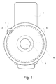
Figure 1 is a schematic view of a starter arrangement according to the present invention. -
Figure 2 is a schematic partial section in the area of the one way clutch through a first embodiment of the starter arrangement according tofig.1 . -
Figure 3 is a schematic partial section in the area of the one way clutch through a second embodiment of the starter arrangement according tofig.1 . -
Figure 4 is a schematic partial section in the area of the one way clutch through a third embodiment of the starter arrangement according tofig.1 . - Still other objects and features of the present invention will become apparent from the following detailed description considered in conjunction with the accompanying drawings. It is to be understood, however, that the drawings are designed solely for purposes of illustration and not as a definition of the limits of the invention, for which reference should be made to the appended claims. It should be further understood that the drawings are not necessarily drawn to scale and that, unless otherwise indicated, they are merely intended to conceptually illustrate the structures and procedures described herein. The same reference numerals will be used for illustrating corresponding features in the different drawings.
- In a preferred first embodiment of the present invention, as shown schematically in
figure 1 , is shown a starter arrangement for an internal combustion engine. The starter arrangement comprises astarter motor 1, e.g. an electrical starter motor, having apinion gear 2 at an output shaft, whichpinion gear 2 is arranged in constant engagement, e.g. through always meshing, with a corresponding crank gear of acrank wheel 3 located between anengine block 4 and a flywheel 13 (seefigs. 2 and3 ) of the engine. - As may be seen from
figure 2 thecrank wheel 3 of this first embodiment is operatively connected to acrankshaft 5 of the engine via a one-way clutch unit 6. The one-way clutch unit 6 is arranged at anengine block 4 side of acrankshaft oil seal 7 enabling lubrication and cooling of the one-way clutch unit 6 by an engine oil of the engine. - The
crank wheel 3 is suitably a ring gear that is arranged to rotate with thestarter 1 and freewheel when the engine runs, thanks to the one-way clutch unit 6. As thestarter 1 is permanently engaged to thering gear 3 the gear design may be refined and optimized for generating a minimum of noise during operation. In the centre of thecrank wheel 3 is arranged the one-way clutch unit 6. The crankcase of the engine is sealed by means of thecrankshaft oil seal 7, which is arranged between the one-way clutch unit 6 and thecrankshaft 5. - A second oils seal (not shown) is suitably arranged between the one-
way clutch unit 6 and theengine block 4 such that engine oil access is restricted to the one-way clutch unit 6 section of the arrangement and engine oil is prevented from entering an associated clutch/converter housing (not shown). - The one-
way clutch unit 6 comprises a tubeshaped hub 8. The tubeshaped hub 8 is pushed onto thecrankshaft 5 and loosely fitted to an end thereof. This end of thecrankshaft 5 is provided with acircumferential slot 9 for receiving aclipring 10. Theslot 9 is thus provided for carrying the clipring 10 axially fixing thehub 8 upon thecrankshaft 5 through thehub 8 being provided with axially delimitingmembers clipring 10. Theclipring 10 is prevented from rotation in theslot 9 of thecrankshaft 5 by its compression or clip force and will guide thehub 8 axially on thecrankshaft 5. - Thus, the
clipring 10 is designed to be clipped on or off by assembly or disassembly force to provide a restriction of movement for the tubeshaped hub 8 located at the end of thecrankshaft 5 between theengine block 4 and theflywheel 13. - Thus is provided a simple solution to fixate a one-
way clutch unit 6 on the end of thecrankshaft 5 of an internal combustion engine essentially consisting of aclipring 10 and acorresponding slot 9, enabling an easy assembly and disassembly function as a cost effective design. - The
crankshaft oil seal 7 is suitably arranged between thehub 8 of the one-way clutch unit 6 and thecrankshaft 5 near the end of thecrankshaft 5 outside the axially delimitingmembers clipring 10 will be lubricated inside thehub 8 together with the other components of the one-way clutch unit 6. - In the first embodiment both the axially delimiting
members hub 8, as illustrated infigure 2 . - In a second embodiment both the axially delimiting
members hub 8, as illustrated infigure 3 . - Alternatively at least one of the axially delimiting
members hub 8. - Yet alternatively at least one of the axially delimiting
members hub 8. - Still alternatively one of the axially delimiting
members 11 is a ring shaped member press fitted into thehub 8 and the other axially delimitingmember 12 is integrally formed with thehub 8, or vice versa. -
Figure 4 illustrates a schematic partial section in the area of the one way clutch through a third embodiment of the starter arrangement. In this third embodiment the end of thecrankshaft 5 is provided with asleeve 14 which is press fitted onto the end of thecrankshaft 5. This may be advantageous in order to provide the end of thecrankshaft 5 with desired characteristics, such as finish and surface hardness. The sleeve is provided with thecircumferential slot 9 carrying theclipring 10. It is obvious that the above may be combined with the first and second embodiments as described above. - Further, in the third embodiment according to
figure 4 , theaxially delimiting member 11 is integrally formed with thesleeve 14 and theaxially delimiting member 12 of thehub 8 arranged in-between the clipring 10 and theaxially delimiting member 11, such that thehub 8 is axially fixed upon thecrankshaft 5. It is clear that also this third embodiment enables an easy assembly and disassembly function, as the press fittedsleeve 14 does not need to be removed for mounting and dismounting of the one-wayclutch unit 6, which also here is facilitated through clipping on and off theclipring 10. - Alternatively, the
axially delimiting member 11 may also be press fitted onto thesleeve 14 and theaxially delimiting member 12 of thehub 8 arranged in-between the clipring 10 and theaxially delimiting member 11, in accordance with the third embodiment. - In accordance with the present invention is also envisaged an automotive vehicle, which comprises a starter arrangement for an internal combustion engine as described above.
- Furthermore, in accordance with the present invention is also envisaged a method for mounting a one-way clutch unit of a starter arrangement for an internal combustion engine. The starter arrangement comprises a
starter motor 1 having apinion gear 2 at an output shaft. Thepinion gear 2 of the starter motor is arranged in constant engagement with a corresponding crank gear of acrank wheel 3 located between anengine block 4 and aflywheel 13 of the engine. Furthermore, thecrank wheel 3 is operatively connected to acrankshaft 5 of the engine via a one-wayclutch unit 6. The method in accordance with the present invention comprises the steps of fitting a tube shapedhub 8 of the one-wayclutch unit 6 loosely to an end of thecrankshaft 5, which end of thecrankshaft 5 is provided with acircumferential slot 9, axially fixing thehub 8 upon thecrankshaft 5 through inserting aclipring 10 into theslot 9 such that thehub 8 is axially fixed upon thecrankshaft 5 through co-operation between axially delimitingmembers clipring 10. - The above method for mounting a one-way
clutch unit 6 of a starter arrangement for an internal combustion engine enables convenient mounting and dismounting of the one-wayclutch unit 6 through clipping on and off theclipring 10. - Modifications to embodiments of the invention described in the foregoing are possible without departing from the scope of the invention as defined by the accompanying claims.
- Expressions such as "including", "comprising", "incorporating", "consisting of", "have", "is" used to describe and claim the present invention are intended to be construed in a non-exclusive manner, namely allowing for items, components or elements not explicitly described also to be present. Reference to the singular is also to be construed to relate to the plural and vice versa.
- Numerals included within parentheses in the accompanying claims are intended to assist understanding of the claims and should not be construed in any way to limit subject matter claimed by these claims.
- Thus, while there have been shown and described and pointed out fundamental novel features of the invention as applied to a preferred embodiment thereof, it will be understood that various omissions and substitutions and changes in the form and details of the devices illustrated, and in their operation, may be made by those skilled in the art. For example, it is expressly intended that all combinations of those elements and/or method steps which perform substantially the same function in substantially the same way to achieve the same results are within the scope of the invention. Moreover, it should be recognized that structures and/or elements and/or method steps shown and/or described in connection with any disclosed form or embodiment of the invention may be incorporated in any other disclosed or described or suggested form or embodiment as a general matter of design choice. It is the intention, therefore, to be limited only as indicated by the scope of the claims appended hereto.
Claims (10)
- Starter arrangement for an internal combustion engine the arrangement comprising a starter motor (1) having a pinion gear (2) at an output shaft, which pinion gear (2) is arranged in constant engagement with a corresponding crank gear of a crank wheel (3) located between an engine block (4) and a flywheel (13) of the engine, which crank wheel (3) is operatively connected to a crankshaft (5) of the engine via a one-way clutch unit (6), characterised in that the one-way clutch unit (6) comprises a tube shaped hub (8) loosely fitted to an end of the crankshaft (5), which end of the crankshaft (5) is provided with a circumferential slot (9) carrying a clipring (10) axially fixing the hub (8) upon the crankshaft (5) in co-operation with axially delimiting members (11, 12).
- A starter arrangement according to claim 1, characterised in that at least one of the axially delimiting members (11, 12) is a ring shaped member press fitted into the hub (8).
- A starter arrangement according to any one of claims 1 to 2, characterised in that at least one of the axially delimiting members (11, 12) is integrally formed with the hub (8).
- A starter arrangement according to any one of claims 1 to 3, characterised in that the end of the crankshaft (5) is provided with a sleeve (14) which is press fitted onto the end of the crankshaft (5), which sleeve is provided with the circumferential slot (9) carrying the clipring (10).
- A starter arrangement according to claim 4, characterised in that the axially delimiting member (11) is press fitted onto the sleeve (14) and the axially delimiting member (12) of the hub (8) arranged in-between the clipring (10) and the axially delimiting member (11).
- A starter arrangement according to claim 4, characterised in that the axially delimiting member (11) is integrally formed with the sleeve (14) and the axially delimiting member (12) of the hub (8) arranged in-between the clipring (10) and the axially delimiting member (11).
- A starter arrangement according to any one of claims 1 to 4, characterised in that the hub (8) is provided with axially delimiting members (11, 12) at either side of the clipring (10).
- A starter arrangement for internal combustion engine according to any one of claims 1 to 7, characterised in that a crankshaft oil seal (7) is arranged between the one-way clutch unit (6) and the crankshaft near the end of the crankshaft (5) outside the axially delimiting members (11, 12).
- An automotive vehicle characterised in that it comprises a starter arrangement for an internal combustion engine according to any one of the preceding claims.
- A method for mounting a one-way clutch unit of a starter arrangement for an internal combustion engine the arrangement comprising a starter motor (1) having a pinion gear (2) at an output shaft, which pinion gear (2) is arranged in constant engagement with a corresponding crank gear of a crank wheel (3) located between an engine block (4) and a flywheel (13) of the engine, which crank wheel (3) is operatively connected to a crankshaft (5) of the engine via the one-way clutch unit (6), characterised in that it comprises the steps of fitting a tube shaped hub (8) of the one-way clutch unit (6) loosely to an end of the crankshaft (5), which end of the crankshaft (5) is provided with a circumferential slot (9), axially fixing the hub (8) upon the crankshaft (5) through inserting a clipring (10) into the slot (9) such that the hub (8) is axially fixed upon the crankshaft (5) through co-operation between axially delimiting members (11, 12) and the clipring (10).
Priority Applications (4)
| Application Number | Priority Date | Filing Date | Title |
|---|---|---|---|
| DE602007012358T DE602007012358D1 (en) | 2007-12-17 | 2007-12-17 | Starter arrangement for an internal combustion engine |
| EP07123346A EP2072807B1 (en) | 2007-12-17 | 2007-12-17 | Starter arrangement for an internal combustion engine |
| CNA200810188463XA CN101463788A (en) | 2007-12-17 | 2008-12-16 | Starter arrangement for an internal combustion engine |
| US12/336,321 US8161933B2 (en) | 2007-12-17 | 2008-12-16 | Starter arrangement for an internal combustion engine |
Applications Claiming Priority (1)
| Application Number | Priority Date | Filing Date | Title |
|---|---|---|---|
| EP07123346A EP2072807B1 (en) | 2007-12-17 | 2007-12-17 | Starter arrangement for an internal combustion engine |
Publications (2)
| Publication Number | Publication Date |
|---|---|
| EP2072807A1 true EP2072807A1 (en) | 2009-06-24 |
| EP2072807B1 EP2072807B1 (en) | 2011-02-02 |
Family
ID=39402901
Family Applications (1)
| Application Number | Title | Priority Date | Filing Date |
|---|---|---|---|
| EP07123346A Not-in-force EP2072807B1 (en) | 2007-12-17 | 2007-12-17 | Starter arrangement for an internal combustion engine |
Country Status (4)
| Country | Link |
|---|---|
| US (1) | US8161933B2 (en) |
| EP (1) | EP2072807B1 (en) |
| CN (1) | CN101463788A (en) |
| DE (1) | DE602007012358D1 (en) |
Cited By (1)
| Publication number | Priority date | Publication date | Assignee | Title |
|---|---|---|---|---|
| WO2011080118A3 (en) * | 2009-12-29 | 2011-09-09 | Robert Bosch Gmbh | Starter for an internal combustion engine |
Families Citing this family (6)
| Publication number | Priority date | Publication date | Assignee | Title |
|---|---|---|---|---|
| JP5425696B2 (en) * | 2010-04-19 | 2014-02-26 | Nskワーナー株式会社 | Engine starter mechanism with one-way clutch |
| KR101501869B1 (en) | 2011-03-31 | 2015-03-18 | 미쓰비시덴키 가부시키가이샤 | Engine starting apparatus |
| WO2012131973A1 (en) * | 2011-03-31 | 2012-10-04 | 三菱電機株式会社 | Engine starting device |
| DE102011081093A1 (en) * | 2011-08-17 | 2013-02-21 | Robert Bosch Gmbh | Starting system, method and computer program product for starting an internal combustion engine |
| US8863721B2 (en) * | 2012-11-30 | 2014-10-21 | GM Global Technology Operations LLC | Seal alignment systems |
| US9051980B2 (en) | 2013-04-26 | 2015-06-09 | Gm Global Technology Operations, Llc | Direction selectable sprag |
Citations (5)
| Publication number | Priority date | Publication date | Assignee | Title |
|---|---|---|---|---|
| JPS59113256A (en) * | 1982-12-20 | 1984-06-29 | Nippon Denso Co Ltd | Combination of overrunning clutch and pinion for use in engine starter |
| JP2000274337A (en) | 1999-03-25 | 2000-10-03 | Mitsubishi Motors Corp | Starter for internal combustion engine |
| JP2000291517A (en) * | 1999-04-05 | 2000-10-17 | Toyota Motor Corp | Engine starter control device |
| JP2002074337A (en) | 2000-08-31 | 2002-03-15 | Nec Corp | Method for restoring movement of three-dimensional structure and camera directly from picture intensity |
| EP1457669A2 (en) * | 2003-03-11 | 2004-09-15 | Denso Corporation | Starter with stopper on clutch inner portion of one-way clutch |
Family Cites Families (7)
| Publication number | Priority date | Publication date | Assignee | Title |
|---|---|---|---|---|
| DE2714029B1 (en) * | 1977-03-30 | 1978-07-06 | Olympia Werke Ag | Hub fastening by means of a locking ring |
| US4197885A (en) * | 1978-03-13 | 1980-04-15 | Facet Enterprises, Inc. | Direct cranking starter device |
| JP4260581B2 (en) | 2003-09-03 | 2009-04-30 | 本田技研工業株式会社 | One-way clutch |
| WO2006016668A1 (en) * | 2004-08-09 | 2006-02-16 | Toyota Jidosha Kabushiki Kaisha | Starting apparatus |
| JP4508027B2 (en) * | 2005-07-29 | 2010-07-21 | トヨタ自動車株式会社 | Internal combustion engine starting torque transmission mechanism |
| JP2007032499A (en) * | 2005-07-29 | 2007-02-08 | Toyota Motor Corp | Internal combustion engine starting torque transmission mechanism |
| EP1908954A1 (en) * | 2006-09-29 | 2008-04-09 | Ford Global Technologies, LLC. | Starter arrangement for an internal combustion engine |
-
2007
- 2007-12-17 DE DE602007012358T patent/DE602007012358D1/en active Active
- 2007-12-17 EP EP07123346A patent/EP2072807B1/en not_active Not-in-force
-
2008
- 2008-12-16 US US12/336,321 patent/US8161933B2/en active Active
- 2008-12-16 CN CNA200810188463XA patent/CN101463788A/en active Pending
Patent Citations (5)
| Publication number | Priority date | Publication date | Assignee | Title |
|---|---|---|---|---|
| JPS59113256A (en) * | 1982-12-20 | 1984-06-29 | Nippon Denso Co Ltd | Combination of overrunning clutch and pinion for use in engine starter |
| JP2000274337A (en) | 1999-03-25 | 2000-10-03 | Mitsubishi Motors Corp | Starter for internal combustion engine |
| JP2000291517A (en) * | 1999-04-05 | 2000-10-17 | Toyota Motor Corp | Engine starter control device |
| JP2002074337A (en) | 2000-08-31 | 2002-03-15 | Nec Corp | Method for restoring movement of three-dimensional structure and camera directly from picture intensity |
| EP1457669A2 (en) * | 2003-03-11 | 2004-09-15 | Denso Corporation | Starter with stopper on clutch inner portion of one-way clutch |
Cited By (2)
| Publication number | Priority date | Publication date | Assignee | Title |
|---|---|---|---|---|
| WO2011080118A3 (en) * | 2009-12-29 | 2011-09-09 | Robert Bosch Gmbh | Starter for an internal combustion engine |
| CN102686871A (en) * | 2009-12-29 | 2012-09-19 | 罗伯特·博世有限公司 | Starter for an internal combustion engine |
Also Published As
| Publication number | Publication date |
|---|---|
| DE602007012358D1 (en) | 2011-03-17 |
| US20090151684A1 (en) | 2009-06-18 |
| EP2072807B1 (en) | 2011-02-02 |
| CN101463788A (en) | 2009-06-24 |
| US8161933B2 (en) | 2012-04-24 |
Similar Documents
| Publication | Publication Date | Title |
|---|---|---|
| EP2072807B1 (en) | Starter arrangement for an internal combustion engine | |
| US20080163842A1 (en) | Starter Arrangement for an Internal Combustion Engine | |
| CN203511265U (en) | Power train of motor vehicle and with internal combustion engine and starting electric generator | |
| EP3461669B1 (en) | Hybrid vehicle | |
| US6599214B2 (en) | Approach to integrating a starter-generator with an automatic transmission | |
| US6631703B2 (en) | Internal combustion engine | |
| KR200487364Y1 (en) | Drive train of a motor vehicle having an internal combustion engine and a starter generator | |
| US20110088649A1 (en) | Flexible Mounting System for Powertrain Mounted Components | |
| CN102913322A (en) | Vehicle accessory drive system | |
| CN102220928B (en) | Engine starter mechanism using one way clutch | |
| JP2002130097A (en) | Dive engine starter | |
| CN201351566Y (en) | Engine starting gear disc structure | |
| US7370619B2 (en) | Starter system for internal combustion engine | |
| EP2093415A2 (en) | Torque transmission apparatus for transmitting driving torque from starter motor to internal combustion engine | |
| EP2028365B1 (en) | Starting device for engines | |
| EP1459931B1 (en) | Transmission gear apparatus for motor vehicle | |
| JP6069110B2 (en) | Starter | |
| US20160040748A1 (en) | Helical flexplate assembly and systems incorporating the same | |
| JP2001213180A (en) | Auxiliary equipment structure of internal combustion engine | |
| CN107554279B (en) | Oil pump system of hybrid electric vehicle and hybrid electric vehicle | |
| GB2580682A (en) | Hybrid vehicle drive lines | |
| EP1916146A3 (en) | Hybrid transmission system for a motor vehicle | |
| RU2624778C1 (en) | Five-stage electric starter | |
| JP2004122980A (en) | Vehicle drive system | |
| KR20050119879A (en) | Electric driving system for hybrid electric vehicle |
Legal Events
| Date | Code | Title | Description |
|---|---|---|---|
| PUAI | Public reference made under article 153(3) epc to a published international application that has entered the european phase |
Free format text: ORIGINAL CODE: 0009012 |
|
| AK | Designated contracting states |
Kind code of ref document: A1 Designated state(s): AT BE BG CH CY CZ DE DK EE ES FI FR GB GR HU IE IS IT LI LT LU LV MC MT NL PL PT RO SE SI SK TR |
|
| AX | Request for extension of the european patent |
Extension state: AL BA HR MK RS |
|
| 17P | Request for examination filed |
Effective date: 20090722 |
|
| AKX | Designation fees paid |
Designated state(s): DE GB SE |
|
| GRAP | Despatch of communication of intention to grant a patent |
Free format text: ORIGINAL CODE: EPIDOSNIGR1 |
|
| GRAS | Grant fee paid |
Free format text: ORIGINAL CODE: EPIDOSNIGR3 |
|
| GRAA | (expected) grant |
Free format text: ORIGINAL CODE: 0009210 |
|
| AK | Designated contracting states |
Kind code of ref document: B1 Designated state(s): DE GB SE |
|
| REG | Reference to a national code |
Ref country code: GB Ref legal event code: FG4D |
|
| REF | Corresponds to: |
Ref document number: 602007012358 Country of ref document: DE Date of ref document: 20110317 Kind code of ref document: P |
|
| REG | Reference to a national code |
Ref country code: DE Ref legal event code: R096 Ref document number: 602007012358 Country of ref document: DE Effective date: 20110317 |
|
| REG | Reference to a national code |
Ref country code: SE Ref legal event code: TRGR |
|
| RAP2 | Party data changed (patent owner data changed or rights of a patent transferred) |
Owner name: VOLVO CAR CORPORATION |
|
| REG | Reference to a national code |
Ref country code: GB Ref legal event code: 732E Free format text: REGISTERED BETWEEN 20111006 AND 20111012 |
|
| REG | Reference to a national code |
Ref country code: DE Ref legal event code: R097 Ref document number: 602007012358 Country of ref document: DE |
|
| PLBE | No opposition filed within time limit |
Free format text: ORIGINAL CODE: 0009261 |
|
| STAA | Information on the status of an ep patent application or granted ep patent |
Free format text: STATUS: NO OPPOSITION FILED WITHIN TIME LIMIT |
|
| 26N | No opposition filed |
Effective date: 20111103 |
|
| REG | Reference to a national code |
Ref country code: DE Ref legal event code: R082 Ref document number: 602007012358 Country of ref document: DE Representative=s name: LOUIS, POEHLAU, LOHRENTZ, DE |
|
| REG | Reference to a national code |
Ref country code: DE Ref legal event code: R081 Ref document number: 602007012358 Country of ref document: DE Owner name: VOLVO CAR CORPORATION, SE Free format text: FORMER OWNER: FORD GLOBAL TECHNOLOGIES, LLC, DEARBORN, MICH., US Effective date: 20120111 Ref country code: DE Ref legal event code: R082 Ref document number: 602007012358 Country of ref document: DE Representative=s name: LOUIS, POEHLAU, LOHRENTZ, DE Effective date: 20120111 Ref country code: DE Ref legal event code: R097 Ref document number: 602007012358 Country of ref document: DE Effective date: 20111103 Ref country code: DE Ref legal event code: R081 Ref document number: 602007012358 Country of ref document: DE Owner name: VOLVO CAR CORPORATION, SE Free format text: FORMER OWNER: FORD GLOBAL TECHNOLOGIES, LLC, DEARBORN, US Effective date: 20120111 |
|
| PGFP | Annual fee paid to national office [announced via postgrant information from national office to epo] |
Ref country code: PT Payment date: 20181017 Year of fee payment: 12 |
|
| PGFP | Annual fee paid to national office [announced via postgrant information from national office to epo] |
Ref country code: GB Payment date: 20181210 Year of fee payment: 12 |
|
| REG | Reference to a national code |
Ref country code: SE Ref legal event code: EUG |
|
| GBPC | Gb: european patent ceased through non-payment of renewal fee |
Effective date: 20191217 |
|
| PG25 | Lapsed in a contracting state [announced via postgrant information from national office to epo] |
Ref country code: SE Free format text: LAPSE BECAUSE OF NON-PAYMENT OF DUE FEES Effective date: 20191218 Ref country code: GB Free format text: LAPSE BECAUSE OF NON-PAYMENT OF DUE FEES Effective date: 20191217 |
|
| P01 | Opt-out of the competence of the unified patent court (upc) registered |
Effective date: 20231212 |
|
| PGFP | Annual fee paid to national office [announced via postgrant information from national office to epo] |
Ref country code: DE Payment date: 20231121 Year of fee payment: 17 |
|
| REG | Reference to a national code |
Ref country code: DE Ref legal event code: R119 Ref document number: 602007012358 Country of ref document: DE |
|
| PG25 | Lapsed in a contracting state [announced via postgrant information from national office to epo] |
Ref country code: DE Free format text: LAPSE BECAUSE OF NON-PAYMENT OF DUE FEES Effective date: 20250701 |