EP2072759A2 - Turbine engine blade with multi-layer protective coating for the interior cooling passages - Google Patents
Turbine engine blade with multi-layer protective coating for the interior cooling passages Download PDFInfo
- Publication number
- EP2072759A2 EP2072759A2 EP08170925A EP08170925A EP2072759A2 EP 2072759 A2 EP2072759 A2 EP 2072759A2 EP 08170925 A EP08170925 A EP 08170925A EP 08170925 A EP08170925 A EP 08170925A EP 2072759 A2 EP2072759 A2 EP 2072759A2
- Authority
- EP
- European Patent Office
- Prior art keywords
- coating
- percent
- airfoil
- chromide
- shank
- Prior art date
- Legal status (The legal status is an assumption and is not a legal conclusion. Google has not performed a legal analysis and makes no representation as to the accuracy of the status listed.)
- Granted
Links
- 238000001816 cooling Methods 0.000 title claims abstract description 50
- 239000011253 protective coating Substances 0.000 title description 4
- 238000000576 coating method Methods 0.000 claims abstract description 219
- 239000011248 coating agent Substances 0.000 claims abstract description 192
- 241000501667 Etroplus Species 0.000 claims abstract description 138
- 239000010953 base metal Substances 0.000 claims abstract description 60
- BASFCYQUMIYNBI-UHFFFAOYSA-N platinum Chemical compound [Pt] BASFCYQUMIYNBI-UHFFFAOYSA-N 0.000 claims abstract description 57
- 229910000951 Aluminide Inorganic materials 0.000 claims abstract description 50
- 229910052697 platinum Inorganic materials 0.000 claims abstract description 28
- 238000000034 method Methods 0.000 claims abstract description 23
- 239000010410 layer Substances 0.000 claims description 46
- 239000011241 protective layer Substances 0.000 claims description 40
- VYZAMTAEIAYCRO-UHFFFAOYSA-N Chromium Chemical compound [Cr] VYZAMTAEIAYCRO-UHFFFAOYSA-N 0.000 claims description 37
- 239000011651 chromium Substances 0.000 claims description 37
- 229910052804 chromium Inorganic materials 0.000 claims description 36
- 239000000203 mixture Substances 0.000 claims description 29
- PXHVJJICTQNCMI-UHFFFAOYSA-N Nickel Chemical compound [Ni] PXHVJJICTQNCMI-UHFFFAOYSA-N 0.000 claims description 24
- 238000009792 diffusion process Methods 0.000 claims description 23
- XAGFODPZIPBFFR-UHFFFAOYSA-N aluminium Chemical compound [Al] XAGFODPZIPBFFR-UHFFFAOYSA-N 0.000 claims description 17
- 229910052782 aluminium Inorganic materials 0.000 claims description 17
- 229910052759 nickel Inorganic materials 0.000 claims description 12
- 239000012535 impurity Substances 0.000 claims description 11
- 229910052735 hafnium Inorganic materials 0.000 claims description 10
- VBJZVLUMGGDVMO-UHFFFAOYSA-N hafnium atom Chemical compound [Hf] VBJZVLUMGGDVMO-UHFFFAOYSA-N 0.000 claims description 10
- 229910052727 yttrium Inorganic materials 0.000 claims description 9
- VWQVUPCCIRVNHF-UHFFFAOYSA-N yttrium atom Chemical compound [Y] VWQVUPCCIRVNHF-UHFFFAOYSA-N 0.000 claims description 9
- 229910017052 cobalt Inorganic materials 0.000 claims description 8
- 239000010941 cobalt Substances 0.000 claims description 8
- GUTLYIVDDKVIGB-UHFFFAOYSA-N cobalt atom Chemical compound [Co] GUTLYIVDDKVIGB-UHFFFAOYSA-N 0.000 claims description 8
- 229910052715 tantalum Inorganic materials 0.000 claims description 8
- GUVRBAGPIYLISA-UHFFFAOYSA-N tantalum atom Chemical compound [Ta] GUVRBAGPIYLISA-UHFFFAOYSA-N 0.000 claims description 8
- ZOXJGFHDIHLPTG-UHFFFAOYSA-N Boron Chemical compound [B] ZOXJGFHDIHLPTG-UHFFFAOYSA-N 0.000 claims description 7
- OKTJSMMVPCPJKN-UHFFFAOYSA-N Carbon Chemical compound [C] OKTJSMMVPCPJKN-UHFFFAOYSA-N 0.000 claims description 7
- 229910052796 boron Inorganic materials 0.000 claims description 7
- 229910052799 carbon Inorganic materials 0.000 claims description 7
- 229910052702 rhenium Inorganic materials 0.000 claims description 7
- WUAPFZMCVAUBPE-UHFFFAOYSA-N rhenium atom Chemical compound [Re] WUAPFZMCVAUBPE-UHFFFAOYSA-N 0.000 claims description 7
- ZOKXTWBITQBERF-UHFFFAOYSA-N Molybdenum Chemical compound [Mo] ZOKXTWBITQBERF-UHFFFAOYSA-N 0.000 claims description 6
- NPXOKRUENSOPAO-UHFFFAOYSA-N Raney nickel Chemical compound [Al].[Ni] NPXOKRUENSOPAO-UHFFFAOYSA-N 0.000 claims description 6
- 229910052750 molybdenum Inorganic materials 0.000 claims description 6
- 239000011733 molybdenum Substances 0.000 claims description 6
- WFKWXMTUELFFGS-UHFFFAOYSA-N tungsten Chemical compound [W] WFKWXMTUELFFGS-UHFFFAOYSA-N 0.000 claims description 6
- 229910052721 tungsten Inorganic materials 0.000 claims description 6
- 239000010937 tungsten Substances 0.000 claims description 6
- 229910000943 NiAl Inorganic materials 0.000 claims description 5
- RTAQQCXQSZGOHL-UHFFFAOYSA-N Titanium Chemical compound [Ti] RTAQQCXQSZGOHL-UHFFFAOYSA-N 0.000 claims description 5
- 229910052719 titanium Inorganic materials 0.000 claims description 5
- 239000010936 titanium Substances 0.000 claims description 5
- 238000009825 accumulation Methods 0.000 claims description 4
- KJTLSVCANCCWHF-UHFFFAOYSA-N Ruthenium Chemical compound [Ru] KJTLSVCANCCWHF-UHFFFAOYSA-N 0.000 claims description 3
- 229910052758 niobium Inorganic materials 0.000 claims description 3
- 239000010955 niobium Substances 0.000 claims description 3
- GUCVJGMIXFAOAE-UHFFFAOYSA-N niobium atom Chemical compound [Nb] GUCVJGMIXFAOAE-UHFFFAOYSA-N 0.000 claims description 3
- 229910052707 ruthenium Inorganic materials 0.000 claims description 3
- 230000001419 dependent effect Effects 0.000 claims 1
- 239000000919 ceramic Substances 0.000 abstract description 22
- 238000007789 sealing Methods 0.000 abstract description 3
- 239000007789 gas Substances 0.000 description 32
- 239000000758 substrate Substances 0.000 description 17
- 239000000567 combustion gas Substances 0.000 description 14
- 230000007613 environmental effect Effects 0.000 description 11
- 230000007797 corrosion Effects 0.000 description 10
- 238000005260 corrosion Methods 0.000 description 10
- 238000000151 deposition Methods 0.000 description 10
- 229910052710 silicon Inorganic materials 0.000 description 9
- 239000010703 silicon Substances 0.000 description 9
- 229910000601 superalloy Inorganic materials 0.000 description 9
- 239000000463 material Substances 0.000 description 8
- 230000008021 deposition Effects 0.000 description 7
- 230000003647 oxidation Effects 0.000 description 7
- 238000007254 oxidation reaction Methods 0.000 description 7
- KDLHZDBZIXYQEI-UHFFFAOYSA-N Palladium Chemical compound [Pd] KDLHZDBZIXYQEI-UHFFFAOYSA-N 0.000 description 6
- 229910045601 alloy Inorganic materials 0.000 description 6
- 239000000956 alloy Substances 0.000 description 6
- 239000012720 thermal barrier coating Substances 0.000 description 6
- 238000013459 approach Methods 0.000 description 5
- QCWXUUIWCKQGHC-UHFFFAOYSA-N Zirconium Chemical compound [Zr] QCWXUUIWCKQGHC-UHFFFAOYSA-N 0.000 description 4
- 238000005229 chemical vapour deposition Methods 0.000 description 4
- 230000006378 damage Effects 0.000 description 4
- 230000000670 limiting effect Effects 0.000 description 4
- 229910052751 metal Inorganic materials 0.000 description 4
- 239000002184 metal Substances 0.000 description 4
- 238000005192 partition Methods 0.000 description 4
- 229910052726 zirconium Inorganic materials 0.000 description 4
- XUIMIQQOPSSXEZ-UHFFFAOYSA-N Silicon Chemical compound [Si] XUIMIQQOPSSXEZ-UHFFFAOYSA-N 0.000 description 3
- -1 ammonium chloride Chemical class 0.000 description 3
- 229910010293 ceramic material Inorganic materials 0.000 description 3
- 239000002826 coolant Substances 0.000 description 3
- 150000004820 halides Chemical class 0.000 description 3
- 229910052763 palladium Inorganic materials 0.000 description 3
- 239000012071 phase Substances 0.000 description 3
- 230000001681 protective effect Effects 0.000 description 3
- 238000012546 transfer Methods 0.000 description 3
- NLXLAEXVIDQMFP-UHFFFAOYSA-N Ammonia chloride Chemical compound [NH4+].[Cl-] NLXLAEXVIDQMFP-UHFFFAOYSA-N 0.000 description 2
- XEEYBQQBJWHFJM-UHFFFAOYSA-N Iron Chemical compound [Fe] XEEYBQQBJWHFJM-UHFFFAOYSA-N 0.000 description 2
- 238000005275 alloying Methods 0.000 description 2
- 238000005266 casting Methods 0.000 description 2
- 238000004891 communication Methods 0.000 description 2
- 238000010586 diagram Methods 0.000 description 2
- 238000009826 distribution Methods 0.000 description 2
- 239000000284 extract Substances 0.000 description 2
- 239000000446 fuel Substances 0.000 description 2
- 230000001965 increasing effect Effects 0.000 description 2
- 230000000873 masking effect Effects 0.000 description 2
- 238000012986 modification Methods 0.000 description 2
- 230000004048 modification Effects 0.000 description 2
- SIWVEOZUMHYXCS-UHFFFAOYSA-N oxo(oxoyttriooxy)yttrium Chemical compound O=[Y]O[Y]=O SIWVEOZUMHYXCS-UHFFFAOYSA-N 0.000 description 2
- RVTZCBVAJQQJTK-UHFFFAOYSA-N oxygen(2-);zirconium(4+) Chemical compound [O-2].[O-2].[Zr+4] RVTZCBVAJQQJTK-UHFFFAOYSA-N 0.000 description 2
- 238000012360 testing method Methods 0.000 description 2
- 238000011144 upstream manufacturing Methods 0.000 description 2
- 229910001233 yttria-stabilized zirconia Inorganic materials 0.000 description 2
- 229910001928 zirconium oxide Inorganic materials 0.000 description 2
- 229910000838 Al alloy Inorganic materials 0.000 description 1
- 229910000599 Cr alloy Inorganic materials 0.000 description 1
- AZDRQVAHHNSJOQ-UHFFFAOYSA-N alumane Chemical group [AlH3] AZDRQVAHHNSJOQ-UHFFFAOYSA-N 0.000 description 1
- 235000019270 ammonium chloride Nutrition 0.000 description 1
- 239000007864 aqueous solution Substances 0.000 description 1
- 230000000903 blocking effect Effects 0.000 description 1
- 230000005465 channeling Effects 0.000 description 1
- 238000006243 chemical reaction Methods 0.000 description 1
- 239000000788 chromium alloy Substances 0.000 description 1
- 238000004140 cleaning Methods 0.000 description 1
- 230000000295 complement effect Effects 0.000 description 1
- 238000007796 conventional method Methods 0.000 description 1
- 238000005336 cracking Methods 0.000 description 1
- 230000007547 defect Effects 0.000 description 1
- 238000005137 deposition process Methods 0.000 description 1
- 230000006866 deterioration Effects 0.000 description 1
- 238000007599 discharging Methods 0.000 description 1
- 230000009429 distress Effects 0.000 description 1
- 239000002019 doping agent Substances 0.000 description 1
- 230000000694 effects Effects 0.000 description 1
- 230000002708 enhancing effect Effects 0.000 description 1
- 230000003628 erosive effect Effects 0.000 description 1
- 229910052742 iron Inorganic materials 0.000 description 1
- 238000003754 machining Methods 0.000 description 1
- 150000002739 metals Chemical class 0.000 description 1
- 229910000907 nickel aluminide Inorganic materials 0.000 description 1
- 125000002524 organometallic group Chemical group 0.000 description 1
- 239000002245 particle Substances 0.000 description 1
- 238000005240 physical vapour deposition Methods 0.000 description 1
- 238000007747 plating Methods 0.000 description 1
- 238000001556 precipitation Methods 0.000 description 1
- 239000002002 slurry Substances 0.000 description 1
- 239000000243 solution Substances 0.000 description 1
- 239000007921 spray Substances 0.000 description 1
- 238000010561 standard procedure Methods 0.000 description 1
- 230000003068 static effect Effects 0.000 description 1
- 230000035882 stress Effects 0.000 description 1
- 238000007740 vapor deposition Methods 0.000 description 1
- 238000005019 vapor deposition process Methods 0.000 description 1
- 239000012808 vapor phase Substances 0.000 description 1
Images


Classifications
-
- F—MECHANICAL ENGINEERING; LIGHTING; HEATING; WEAPONS; BLASTING
- F01—MACHINES OR ENGINES IN GENERAL; ENGINE PLANTS IN GENERAL; STEAM ENGINES
- F01D—NON-POSITIVE DISPLACEMENT MACHINES OR ENGINES, e.g. STEAM TURBINES
- F01D5/00—Blades; Blade-carrying members; Heating, heat-insulating, cooling or antivibration means on the blades or the members
- F01D5/12—Blades
- F01D5/14—Form or construction
- F01D5/18—Hollow blades, i.e. blades with cooling or heating channels or cavities; Heating, heat-insulating or cooling means on blades
- F01D5/187—Convection cooling
-
- F—MECHANICAL ENGINEERING; LIGHTING; HEATING; WEAPONS; BLASTING
- F01—MACHINES OR ENGINES IN GENERAL; ENGINE PLANTS IN GENERAL; STEAM ENGINES
- F01D—NON-POSITIVE DISPLACEMENT MACHINES OR ENGINES, e.g. STEAM TURBINES
- F01D5/00—Blades; Blade-carrying members; Heating, heat-insulating, cooling or antivibration means on the blades or the members
- F01D5/12—Blades
- F01D5/28—Selecting particular materials; Particular measures relating thereto; Measures against erosion or corrosion
- F01D5/288—Protective coatings for blades
-
- F—MECHANICAL ENGINEERING; LIGHTING; HEATING; WEAPONS; BLASTING
- F05—INDEXING SCHEMES RELATING TO ENGINES OR PUMPS IN VARIOUS SUBCLASSES OF CLASSES F01-F04
- F05D—INDEXING SCHEME FOR ASPECTS RELATING TO NON-POSITIVE-DISPLACEMENT MACHINES OR ENGINES, GAS-TURBINES OR JET-PROPULSION PLANTS
- F05D2230/00—Manufacture
- F05D2230/30—Manufacture with deposition of material
- F05D2230/31—Layer deposition
-
- F—MECHANICAL ENGINEERING; LIGHTING; HEATING; WEAPONS; BLASTING
- F05—INDEXING SCHEMES RELATING TO ENGINES OR PUMPS IN VARIOUS SUBCLASSES OF CLASSES F01-F04
- F05D—INDEXING SCHEME FOR ASPECTS RELATING TO NON-POSITIVE-DISPLACEMENT MACHINES OR ENGINES, GAS-TURBINES OR JET-PROPULSION PLANTS
- F05D2230/00—Manufacture
- F05D2230/80—Repairing, retrofitting or upgrading methods
-
- F—MECHANICAL ENGINEERING; LIGHTING; HEATING; WEAPONS; BLASTING
- F05—INDEXING SCHEMES RELATING TO ENGINES OR PUMPS IN VARIOUS SUBCLASSES OF CLASSES F01-F04
- F05D—INDEXING SCHEME FOR ASPECTS RELATING TO NON-POSITIVE-DISPLACEMENT MACHINES OR ENGINES, GAS-TURBINES OR JET-PROPULSION PLANTS
- F05D2230/00—Manufacture
- F05D2230/90—Coating; Surface treatment
-
- Y—GENERAL TAGGING OF NEW TECHNOLOGICAL DEVELOPMENTS; GENERAL TAGGING OF CROSS-SECTIONAL TECHNOLOGIES SPANNING OVER SEVERAL SECTIONS OF THE IPC; TECHNICAL SUBJECTS COVERED BY FORMER USPC CROSS-REFERENCE ART COLLECTIONS [XRACs] AND DIGESTS
- Y02—TECHNOLOGIES OR APPLICATIONS FOR MITIGATION OR ADAPTATION AGAINST CLIMATE CHANGE
- Y02T—CLIMATE CHANGE MITIGATION TECHNOLOGIES RELATED TO TRANSPORTATION
- Y02T50/00—Aeronautics or air transport
- Y02T50/60—Efficient propulsion technologies, e.g. for aircraft
Landscapes
- Engineering & Computer Science (AREA)
- Mechanical Engineering (AREA)
- General Engineering & Computer Science (AREA)
- Chemical & Material Sciences (AREA)
- Materials Engineering (AREA)
- Turbine Rotor Nozzle Sealing (AREA)
- Other Surface Treatments For Metallic Materials (AREA)
Abstract
Description
- This invention relates generally to turbine engines, and more specifically to protective environmental coatings placed on turbine engine components such as turbine blades and vanes.
- In a gas turbine engine, air is pressurized in a compressor and mixed with fuel in a combustor for generating hot combustion gases. A high pressure turbine (HPT) follows the combustor and extracts energy from the combustion gases for powering the compressor. A low pressure turbine (LPT) follows the HPT and extracts additional energy from the combustion gases for powering an upstream fan in an aircraft turbofan engine application, or powers an external drive shaft for marine and industrial applications.
- The turbines are arranged in stages including a stationary turbine nozzle having a row of vanes which direct the combustion gases into a corresponding row of turbine rotor blades. Each vane has an airfoil configuration extending radially in span between inner and outer bands which bound the combustion gases.
- Each turbine blade includes an airfoil extending radially outward in span from an airfoil root at an integral platform. An integral blade shank extends between the platform and an integral dovetail for mounting the blade in a corresponding dovetail slot in the perimeter of a supporting rotor disk. The platform defines the inner boundary for combustion gases, and the radially outer tip of the airfoil is spaced closely adjacent to a surrounding turbine shroud that defines the outer boundary for the combustion gases. The shank supports the mechanical loads from the airfoil and platform and transfers these mechanical loads to the blade dovetail. The shank has interior passages in it which are in flow communication with the cooling passages inside the airfoil. The shank interior passages receive cooling air through passages in the blade dovetail and channel the cooling flow into the airfoil cooling circuits.
- The corresponding airfoils of the vanes and blades in each turbine stage have generally concave pressure sides and generally convex suction sides extending axially in chord between opposite leading and trailing edges for efficiently turning the combustion gases and extracting energy therefrom during operation. The differently shaped opposite sides of the airfoils therefore effect different velocity and pressure distributions thereover, and correspondingly experience different heat loads from the combustion gases in highly complex three dimensional (3D) distributions.
- The first stage turbine nozzle and blades first receive the hot combustion gases from the combustor and therefore have the greatest heat loads of the various turbine stages. Accordingly, the vanes and blades are typically cast from state of the art superalloy metals which have enhanced strength at elevated temperature for maximizing the useful life thereof during operation. In conventional engines, the turbine vanes and blades are made of nickel based superalloys, and can operate at temperatures of up to about 1900-2100 Deg. F. A protective layer or a metal/ceramic thermal barrier coating (TBC) system is sometimes applied to the airfoil, which acts to protect the base substrate metal of the component.
- The blade airfoil and shank are hollow and include corresponding internal cooling circuits therein which receive a portion of the pressurized air bled from the compressor for cooling thereof during operation. The internal cooling channels located inside the blade shank typically include multiple radial channels defined by corresponding radial partition walls. The internal cooling circuits in the airfoil have multiple radial channels having walls that bridge the pressure and suction sides of the airfoil. The pressure and suction sides of the airfoil typically include radial rows or columns of film cooling holes extending transversely through airfoil walls.
- The gas turbine blade or vane may be operated in a highly aggressive environment that may cause deterioration of the component in service. The environmental damage may be in various forms, such as particle erosion, different types of corrosion, and oxidation, and complex combinations of these damage modes, in the hot combustion gas environment. The rate of environmental damage may be lessened somewhat with the use of coatings comprising suitable protective layers.
- In conventional turbine engine components aluminide coatings have been used in the internal passages of turbine blades and vanes to avoid failures from internal oxidation of the bare nickel superalloy base material. Although turbine blade alloys having greater oxidation resistance have been developed, these newer alloys may not possess adequate hot corrosion resistance. It is known in the art that oxidation of the parent material in the cooler internal blade passages is usually not very significant. However, under certain conditions hot corrosion in the cooler internal shank cavities may occur if the protective environmental coating does not provide sufficient protection against corrosive environments.
- Conventional turbine engine components are typically made from nickel based superalloys. Aluminide environmental coatings are sometimes used in these conventional turbine engine components to protect the internal passages from oxidation and hot corrosion. Aluminide coatings are relatively more brittle as compared to the nickel based superalloy base material on which they are applied. Due to the brittle nature of aluminide coatings, cracks may initiate in the internal passages of turbine blades, especially in cooler and thicker areas of aluminide coating such as the blade shank. Therefore, in the relatively cooler locations of the interior passages of the turbine blade it is desirable to have an environmental coating that does not develop cracks.
- Accordingly, it would be desirable to have a turbine blade having a ductile environmental coating to protect the relatively cooler internal passages from hot corrosion.
- The above-mentioned need or needs may be addressed by various exemplary embodiments of the present invention which provide a gas turbine blade comprising a base metal, a platform, an airfoil extending upwardly from the platform, a shank extending downwardly from the platform. The shank has an exterior wall and an internal passage, and the airfoil has a cooling flow channel inside the airfoil for flowing a cooling flow therethrough. The blade has a first chromide coating contacting the base metal of at least a portion of an interior surface of the shank and interdiffused therewith, wherein the first chromide coating does not have an aluminide coating deposited over it. The blade has a second chromide coating contacting the base metal of at least a portion of an interior surface of the airfoil and interdiffused therewith. A method for preparing a gas turbine blade comprises the steps of applying chromide coatings, sealing the interior passages of the shank and airfoil in order to prevent aluminide coating in the internal region of the shank and to reduce aluminide coating in the internal region of the airfoil, and applying an aluminide or platinum aluminide coating and an optional ceramic layer on the external region of the airfoil.
- In one embodiment, the first chromide coating comprises an average of from about 20 to about 50 percent by weight chromium and has a thickness of from about 0.0005 to about 0.002 inch.
- In another embodiment, an optional third and optional fourth chromide coatings are used. In a variation of this embodiment, the first, second, third and fourth chromide coatings have the same composition and are applied concurrently.
- In another embodiment, the airfoil has a multi-layer coating comprising an aluminide or platinum aluminide coating overlying a chromide coating on at least a portion of the exterior surface of the airfoil. An optional ceramic layer may be used.
- A method for preparing a gas turbine blade includes the steps of applying the first, second, optional third and optional fourth chromide coatings, substantially sealing the interior passages of the blade shank and airfoil in order to prevent aluminide coating in the internal region of the shank and to reduce aluminide coating in the internal region of the airfoil, and then applying an aluminide coating to at least a part of the external region of the airfoil. In another embodiment, the method further includes the step of applying a ceramic layer to at least a part of the airfoil.
- The subject matter which is regarded as the invention is particularly pointed out and distinctly claimed in the concluding part of the specification. The invention, however, may be best understood by reference to the following description taken in conjunction with the accompanying drawing figures in which:
-
Figure 1 is an isometric view of an exemplary turbine rotor blade. -
Figure 2 is an elevational sectional view through the blade illustrated inFigure 1 . -
Figure 3 is an enlarged schematic sectional view through the shank portion of the turbine blade ofFigure 2 , taken on line 3-3. -
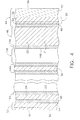
Figure 4 is an enlarged schematic sectional view through the airfoil portion of the turbine blade ofFigure 1 , taken on line 4-4. -
Figure 5 is a block flow diagram of an exemplary embodiment of an approach for preparing a coated gas turbine component. - Referring to the drawings wherein identical reference numerals denote the same elements throughout the various views,
Figure 1 shows an exemplary,turbine rotor blade 10 for use in a gas turbine engine. The blade includes anairfoil 12,platform 14, ashank 18 and supportingdovetail 16 formed in a unitary configuration by casting. Theplatform 14 defines a radially inner boundary forhot combustion gases 19 generated in an upstream combustor (not shown) which flow axially downstream over theairfoil 12 during operation. Theturbine blade 10 is formed of any operable material, preferably a nickel-base superalloy, which is the base metal of theturbine blade 10. The base metal of the turbine blade serves as a substrate, for example, shown asitems Figures 3 and4 , for the coatings that are described subsequently. - The
airfoil 12 and theshank 18 are hollow for receiving acooling air coolant 20 throughcorresponding inlets 17 in the base of thedovetail 16 for cooling the blade during operation. Thedovetail 16 is configured with supporting lobes or tangs that mate with a corresponding dovetail slot in the perimeter of a supporting rotor disk (not shown) from which the blade extends radially outwardly in the engine. - The disk includes a full row or complement of the
blades 10 for extracting energy from the combustion gases for rotating the disk and in turn powering the compressor (not shown) of the engine which produces the pressurizedcooling air 20. Most of the air pressurized in the compressor is mixed with fuel in the combustor for generating thehot combustion gases 19, and a small portion of the pressurized air is bled from the compressor for cooling the row of turbine blades. - The
airfoil 12 includes a generallyconcave pressure sidewall 22, and a circumferentially opposite, generally convexsuction sidewall 24 extending in radial or longitudinal span from a radiallyinner root 26 where the proximal end of the airfoil meets theplatform 14, to a radiallyouter tip 28 at the opposite distal end of the airfoil. The twosidewalls trailing edges - The hollow blade illustrated in
Figure 1 is shown split in section inFigure 2 and includes aninternal cooling circuit 34 for channeling thepressurized air coolant 20 radially outwardly therethrough during operation. The two sidewalls of the airfoil are spaced circumferentially or transversely apart between the leading and trailing edges and are joined together by a plurality of chordally spaced apart internal partitions or bridges 36 which extend radially in span to define corresponding channels of thecooling circuit 34. Thepressure sidewall 22 and thesuction sidewall 24 include cooling holes 38 and 40 extending transversely therethrough in flow communication with theinternal cooling circuit 34 for discharging thecoolant 20 during operation. The multitude of cooling holes 38, 40 are different forms of film cooling holes strategically distributed over the span and chord of the pressure sidewall and suction side wall to improve the film cooling thereof and address the thermal distress discovered in the parent blade due to extended use of this type of turbine blade in years of commercial service. - The blade receives cooling
air 20 through the dovetailinternal passages 82 located inside theblade dovetail 16. The cooling air passes through the shankinternal passages 84 located inside theshank 18 of the blade and enters the airfoilinternal cooling circuit 34. Theblade shank 18 is disposed between theblade platform 14 and thedovetail 16. Theinterior passages 84 of theshank 18 are formed by theshank exterior walls 71 and the shankinterior walls 73. The blade dovetailinterior passages 82 are formed by thedovetail exterior walls 72 and the dovetailinterior walls 74. Theshank walls blade airfoil 12 and theplatform 14 and transfer these loads to the dovetails 16, which in turn transfer them to the supporting disk dovetails. - The
basic turbine blade 10 illustrated inFigure 1 is representative of the exemplary parent turbine blade disclosed above which has enjoyed years of commercial use in the United States and foreign countries, but is specifically modified as disclosed herein for further enhancing life thereof by improving the environmental resistance in the interior passages of the blade. Accordingly, the turbine rotor blade illustrated inFigure 1 may be otherwise conventional in the form of the parent blade for enjoying the long useful life thereof, while being specifically modified locally in the shank and dovetail regions thereof for improving environmental resistance of the interior cooling passages for further increasing the blade useful life. -
Figures 3 schematically illustratesexemplary chromide coatings metal substrates shank 18 of aturbine blade 10. A optionalfourth chromide coating 101 is applied on theouter surfaces exterior walls 71 of theshank 18. Afirst chromide coating 102 is applied on theinterior surfaces exterior walls 71 and thesurfaces internal passage walls 73 of theshank 18. Referring toFigure 3 , the optionalfourth chromide coating 101 is applied to and contacts asubstrate base metal 71 of at least a portion of theshank 18. The optionalfourth chromide coating 101 is at least partially interdiffused with thebase metal 71 of theshank 18. The optionalfourth chromide coating 101 forms the entire coating on the outside of theshank 18, in the preferred form illustrated inFigure 3 . The optionalfourth chromide coating 101 may be any operable chromide composition, and is preferably an average composition of from about 20 to about 50 weight percent chromium, balance interdiffused elements of the base metal, and impurities. (The term "chromide" does not suggest a particular composition such as an intermetallic composition, and instead indicates an elevated chromium composition.) Other modifying elements such as silicon may be co-deposited with the chromium, and become part of the optionalfourth chromide coating 101. The optionalfourth chromide coating 101 is preferably from about 0.0005 to about 0.002 inch thick. Thefourth chromide coating 101 may optionally be applied to a portion of theplatform 14, and optionally, to a portion of thedovetail 16. Thefourth chromide coating 101 may optionally be applied to a portion of theairfoil 12. - The
first chromide coating 102 comprises a chromide layer overlying and contacting thesubstrate base metal shank 18. Thefirst chromide coating 102 is at least partially interdiffused with thebase metal dovetail 18. Thefirst chromide coating 102 may be any operable chromide material or composition, and preferably comprises an average composition of from about 20 to about 50 weight percent chromium, balance interdiffused elements of the base metal, and impurities. Other modifying elements such as silicon may be co-deposited with the chromium, and become part of thefirst chromide coating 102. Thefirst chromide coating 102 is preferably from about 0.0005 to about 0.002 inch thick. - A chromide coating, such as the
first chromide coat 102, in the internal passages of aturbine blade shank 18 provides a ductile and hot corrosion resistant coating in the shank of these turbine blades. Using ductile chromide and substantially limiting brittle aluminide in the shank cavities prevents coating cracking and avoids blade failure. - Chromide coating also provides increased hot corrosion resistance and sufficient oxidation resistance at the lower temperatures that are experienced within the interior airfoil passages as compared to the external blade surface. It has been found by testing that for a conventional turbine alloy, Rene 142, a chromide coating, as disclosed and described herein, provided an improved low cycle (LCF) capability of about 20,000 psi in alternating stress for typical LCF life between 10000 cycles to 100000 cycles, as compared to conventional aluminide coating. In accelerated hot corrosion tests, simulating the low temperature environment of the
blade shank 18, the chromide coating was not damaged after 15 cycles whereas conventional aluminide coating showed damage after 1 cycle. -
Figures 4 schematically illustrates an exemplarymulti-layer coating system 44 comprising an optionalthird chromide coating 48, a platinum-aluminide coating 50, and an optional-but-preferred ceramicthermal barrier coating 52 applied to theairfoil 12 of theturbine blade 10. Referring toFigure 4 , the exemplarymulti-layer coating system 44 is applied to and contacts at least a portion of thethird chromide coating 48 on theairfoill 12. Thesubstrate base metal 46 of theairfoil 12 is usually of the same composition as thesubstrate base metal 71 of theshank 18, because theentire turbine blade 10 is typically cast as an integral piece of a single composition of metal. Optionally, themulti-layer coating system 44 may also be applied to a portion of thetop side 13 of theplatform 14. - The
multi-layer coating system 44 comprises optionalthird chromide coating 48 overlying and contacting thesubstrate base metal 46 of theairfoil 12. The optionalthird chromide coating 48 is at least partially interdiffused with thebase metal 46 of theairfoil 12. The optionalthird chromide coating 48 may be any operable chromide material or composition, and preferably comprises an average composition of from about 20 to about 50 weight percent chromium, balance interdiffused elements of the base metal, and impurities. Other modifying elements such as silicon may be co-deposited with the chromium, and become part of the optionalthird chromide coating 48. The optionalthird chromide coating 48 is preferably from about 0.0005 to about 0.002 inch thick. It is preferred that the optionalthird chromide coating 48 be of substantially the same composition and thickness as the optionalfourth chromide coating 101 applied to theshank 18, and that the optionalfourth chromide coating 101 and the optionalthird chromide coating 48 be applied to thesubstrate 21 at the same time and using the same technique, as will be discussed in more detail subsequently. -
Figure 4 schematically illustrates asecond chromide coating 144 applied to the interior surfaces of theairfoil 12 and theinternal partitions 36 forming theinternal cooling circuits 34. Thesecond chromide coating 144 comprises a chromide layer overlying and contacting thesubstrate base metal 21 of thepressure side wall 22 of theairfoil 12,substrate base metal 23 of thesuction side wall 24 of theairfoil 12 and the internal cooling passagepartition wall substrate 36 of theairfoil 12. Thesecond chromide coating 144 is at least partially interdiffused with the corresponding substrate base metal of theairfoil 12 on which it is applied. Thesecond chromide coating 144 may be any operable chromide material or composition, and preferably comprises an average composition of from about 20 to about 50 weight percent chromium, balance interdiffused elements of the base metal, and impurities. Other modifying elements such as silicon may be co-deposited with the chromium, and become part of thesecond chromide coating 144. Thesecond chromide coating 144 is preferably from about 0.0005 to about 0.002 inch thick. - It is preferred that the first, second, optional third and the optional fourth chromide coatings, 102, 144, 48 and 101 respectively, be of substantially the same composition and thickness. It is preferred that the first, second, optional third and the optional fourth chromide coatings, 102, 144, 48 and 101 respectively, be applied to their respective substrates at the same time and using the same technique, as will be discussed in more detail subsequently.
- The
multi-layer coating system 44 comprises aprotective layer 50. Theprotective layer 50 overlies and contacts the optionalthird chromide coating 48. Theprotective layer 50 preferably comprises either a diffusion aluminide or a diffusion platinum aluminide. The preferred diffusion aluminideprotective layer 50 preferably comprises aluminum modified by the addition of the following elements to improve corrosion resistance: chromium, hafnium, silicon, zirconium, yttrium, platinum, and palladium, and combinations thereof The modifying element is present in an effective amount. Typical amounts of the modifying elements that are present, either alone or in combination in compatible compositions, include, in weight percent, from about 2 to about 50 percent chromium, from about 0.1 to about 20 percent hafnium, from about 0.1 to about 10 percent silicon, from about 0.1 to about 5 percent zirconium, from about 0.1 to about 5 percent yttrium, from about 0.1 to about 50 percent palladium, and from about 0.1 to about 50 percent platinum (in which case theprotective layer 50 is termed a platinum aluminide). The aluminum and the corrosion-improving modifying element are at least partially interdiffused with thesubstrate base metal 46 and the optionalthird chromide coating 48, rather than being present as an overlay coating. Theprotective layer 50 is preferably from about 0.0005 inch to about 0.005 inch thick. - The
protective layer 50 may instead be a MCrAlX overlay protective layer or a NiAl intermetallic overlay protective layer. MCrAlX overlay protective layers are known in the art (see, for example,US Patents 4,321,411 ,4,401,697 and4,405,659 ). MCrAlX overlay protective layers primarily have high Cr and a beta/gamma phase structure. Nickel aluminide protective overlays, such as NiAlCrZr, are of a predominantly beta NiAl phase and are known in the art in (see, for example,6,153,313 ,6,255,001 , and 6,291,084). The terminology "MCrAlX" is a shorthand term of art for a variety of families of overlay protective layers that may be employed as environmental coatings or bond coats in thermal barrier coating systems. In this and other forms, M refers to nickel, cobalt, iron, and combinations thereof. In some of these protective coatings, the chromium may be omitted. The MCrAlX overlay protective layer and the NiAl intermetallic overlay protective layer may optionally contain elements such as hafnium, zirconium, yttrium, tantalum, rhenium, platinum, silicon, titanium, boron, carbon, and combinations thereof. Specific compositions are known in the art. Some example compositions include NiAlCrZr and NiAlCrY, but this listing of examples is not to be taken as limiting. The overlay protective coatings may interdiffuse with thesubstrate base metal 46 and the optionalthird chromide coating 48, but any such interdiffusion is relatively slight so that the overlay protective coatings remains discrete. - Optionally, the
multi-layer coating system 44 may further comprise aceramic layer 52 overlying and contacting theprotective layer 50. Theceramic layer 52 is a ceramic material that serves as a thermal barrier coating to insulate the underlying layers. Theceramic layer 52 is usually applied only in those regions of theairfoil 12 that are subjected to the highest temperatures. For example, themulti-layer coating system 44 as applied to thesuction side 24 may not require the use of theceramic layer 52, while themulti-layer coating system 44 as applied to the high-pressure side 22 may include theceramic layer 52. Theceramic layer 52 is preferably yttria stabilized zirconia, which is zirconium oxide containing from about 2 to about 12 weight percent, preferably from about 3 to about 8 weight percent, of yttrium oxide. Theceramic layer 52 is typically from about 0.003 to about 0.010 inch thick. Other operable ceramic materials and thicknesses may be used as well. When there is noceramic layer 52 present, themulti-layer coating system 44 is termed an "environmental coating". When there is aceramic layer 52 present, themulti-layer coating system 44 is termed a "thermal barrier coating system", and the optionalthird chromide coating 48 and theprotective layer 50 serve as the "bond coat" for theceramic layer 52. -
Figure 5 depicts in block diagram form an exemplary embodiment of a method for coating turbine component with chromide coatings. A turbine component is provided, numeral 70. The turbine component is preferably theturbine blade 10 ofFigure 1 . The turbine component is typically cast to the desired shape, as in the case of theturbine blade 10. The chromide coatings are applied to the turbine blade at the cast or machined level using any conventional deposition process, preferably using a vapor deposition process. The furnished turbine component is in a clean state, or may be cleaned of surface residue, casting defects, and the like in this step 70, using standard procedures. The turbine component may be made of any operable material, with a nickel-base superalloy being preferred. As used herein, "nickel-base" means that the composition has more nickel present than any other element. The nickel-base superalloys are typically of a composition that is strengthened by the precipitation of gamma-prime phase. The preferred nickel-base alloy has a composition, in weight percent, of from about 4 to about 20 percent cobalt, from about 1 to about 10 percent chromium, from about 5 to about 7 percent aluminum, from 0 to about 2 percent molybdenum, from about 3 to about 8 percent tungsten, from about 4 to about 12 percent tantalum, from 0 to about 2 percent titanium, from 0 to about 8 percent rhenium, from 0 to about 6 percent ruthenium, from 0 to about 1 percent niobium, from 0 to about 0.1 percent carbon, from 0 to about 0.01 percent boron, from 0 to about 0.1 percent yttrium, from 0 to about 1.5 percent hafnium, balance nickel and incidental impurities. - A most preferred alloy composition is Rene' N5, which has a nominal composition in weight percent of about 7.5 percent cobalt, about 7 percent chromium, about 6.2 percent aluminum, about 6.5 percent tantalum, about 5 percent tungsten, about 1.5 percent molybdenum, about 3 percent rhenium, about 0.05 percent carbon, about 0.004 percent boron, about 0.15 percent hafnium, up to about 0.01 percent yttrium, balance nickel and incidental impurities. Other operable superalloys include, for example, Rene' N6, which has a nominal composition in weight percent of about 12.5 percent cobalt, about 4.2 percent chromium, about 1.4 percent molybdenum, about 5.75 percent tungsten, about 5.4 percent rhenium, about 7.2 percent tantalum, about 5.75 percent aluminum, about 0.15 percent hafnium, about 0.05 percent carbon, about 0.004 percent boron, about 0.01 percent yttrium, balance nickel and incidental impurities; Rene' 142, which has a nominal composition in weight percent of about 6.8 percent chromium, about 12.0 percent cobalt, about 1.5 percent molybdenum, about 2.8 percent rhenium, about 1.5 percent hafnium, about 6.15 percent aluminum, about 4.9 percent tungsten, about 6.35 percent tantalum, about 150 parts per million boron. about 0.12 percent carbon, balance nickel and incidental impurities. The use of the present invention is not limited to turbine components made of the preferred alloy described herein, and has broader applicability.
- In the next four steps, 171, 172, 173 and 174, chromide coatings are applied to their respective locations on the
blade 10. Specifically, thefirst chromide coating 102 is applied (numeral 171) to the interior passage surfaces 113, 114, 115 and 116 of theshank 18; thesecond chromide coating 144 is applied (numeral 172) to the interior surfaces of the airfoilpressure side wall 22 andsuction side wall 24 and to the surfaces of the airfoil internalcooling passage walls 36 as discussed previously; the optionalthird chromide coating 48 is applied (numeral 173) to the outside surface of theairfoil 12pressure side wall 22 andsuction side wall 24; and, the optionalfourth chromide coating 101 is applied (numeral 174) to theoutside surface shank 18. The sequence of steps described above is meant to be only exemplary and is not limiting. Thesteps - In an exemplary embodiment of the invention, the first, second, third and fourth chromide coatings (
items Figures 3 and4 ) are applied simultaneously, by simultaneously performingsteps Figure 5 . Any portions of theturbine blade 10 which are not to be coated with the chromide coating, such as portions of thedovetail 16, may be masked using conventional masking techniques to prevent coating thereon. Thesteps turbine blade 10 is exposed to elevated temperature, but without deposition of additional chromium. The result of the deposition of chromium and simultaneous and/or subsequent interdiffusion is thefirst chromide coating 102, thesecond chromide coating 144, thethird chromide coating 48 and thefourth chromide coating 101, each about 0.0005 to about 0.002 inch thick and having a composition of an average of from about 20 to about 50 weight percent chromium, the chromide-modifying elements, if any, and balance the elements of the base metal and impurities. With this technique, thefirst chromide coating 102, thesecond chromide coating 144, the optionalthird chromide coating 48 and the optionalfourth chromide coating 101 are deposited and interdiffused with the base metal in from about 1 to 10 hours, preferably from about 1 to about 4 hours, most preferably about 2 hours. This completes the application of the chromide coatings, except for any post-application steps such as machining or cleaning that are known in the art. - In the
next step 180, the internal passages of the blade are blocked off to substantially prevent a subsequent coating of the internal passages during subsequent coating applications, such as the platinum-aluminide coating, on the outside of theairfoil 12. Exemplary methods of limiting further coating of the internal surfaces of the blade are using static vapor processes, using pack aluminiding process, or masking of internal passages. The preferred method is to block the blade dovetail openings, such as theinlets 17, while leaving the blade airfoil holes 38, 40 open. The aluminide coating cycle is done preferably with no forced flow through the blade internal passages such asitems Figure 2 . By blocking the blade dovetail openings, the blade shankinternal passages 84 will not be coated with aluminide and the airfoilinternal passages 34 will have only a minimal aluminide coating. - In the next steps,
numerals protective layer 50 of themulti-layer coating 44 is applied. The step of platinum plating, numeral 182, is optional. Theprotective layer 50 is preferably a diffusion aluminide or a diffusion platinum aluminide, optionally modified by the presence of alloying elements. Coating of theturbine blade 10 with diffusion aluminide or diffusion platinum aluminide, can be performed by conventional methods known in the art. Theprotective layer 50 of thesecond coating 44 is applied, numeral 184. Theprotective layer 50 is preferably a diffusion aluminide or a diffusion platinum aluminide, optionally modified by the presence of alloying elements. In the case of a diffusion aluminide, the source of aluminum is preferably a gaseous source, as in vapor phase aluminiding. In this approach, a halide gas is contacted with aluminum metal or an aluminum alloy to form the corresponding aluminum halide gas. Aluminide-modifying elements, such as hafnium, zirconium, yttrium, silicon, titanium, tantalum, cobalt, chromium, platinum, and palladium, may optionally be doped from similar sources into the gaseous source. The source gas is contacted to the portions of the turbine blade which are to be protected by theprotective layer 50 of themulti-layer coating 44. This may include the surfaces already having chromide coatings, such as forexample item 48. Aluminum, with any optional dopants included, is deposited onto the contacted surface. The deposition reaction typically occurs at elevated temperature such as from about 1800 Deg.F to about 2100 Deg.F so that deposited aluminum atoms interdiffuse into the base metal and the optionalthird chromide coating 48. (The chromium atoms of other chromide coatings that may be present at other locations, such as theshank 18, also may continue to interdiffuse with the base metal during this elevated-temperature operation.) An aluminum coating about 0.002 inch thick may be deposited in about 4-8 hours using this approach. Other known and operable aluminum-deposition techniques such as pack cementation, above-the-pack aluminiding, slurry deposition, chemical vapor deposition (CVD), and organo-metallic chemical vapor deposition may also be used. - If the
multi-layer coating system 44 is to have a diffusion platinum aluminide, asublayer 54 of platinum may be deposited onto the optionalthird chromide coating 48, before thesublayer 56 of aluminum is deposited over thesublayer 54 of platinum. The combination of the optionalthird chromide coating 48 and a platinum-aluminideprotective layer 50 gives particularly good corrosion and oxidation resistance in the service temperature range of operation. The deposition of thesublayer 54 of platinum is accomplished by depositing platinum from solution onto the optionalthird chromide coating 48. An operable platinum-containing aqueous solution is Pt(NH3)4HPO4 having a concentration of about 4-20 grams per liter of platinum, and a voltage/current source is operated at about 1/2-10 amperes per square foot of facing article surface. Theplatinum sublayer 54 about 5 micrometers thick is deposited in 1-4 hours at a temperature of 190-200 Deg.F. Thealuminum sublayer 56 is thereafter deposited overlying theplatinum sublayer 54, using the aluminum deposition approach described above. A significant amount of interdiffusion of theplatinum sublayer 54, thealuminum sublayer 56, the optionalthird chromide coating 48 and thesubstrate base metal 46 is achieved during the aluminum deposition. Additional interdiffusion may be accomplished if desired by maintaining the structure at elevated temperature after the flow of halide gas is discontinued. - In the next optional step, numeral 186 of
Figure 5 , theceramic layer 52 is optionally deposited overlying theprotective layer 50 of themulti-layer coating 44. Theceramic layer 52 is preferably from about 0.003 to about 0.010 inch thick, most preferably about 0.005 inch thick. Theceramic layer 52 is preferably yttria stabilized zirconia, which is zirconium oxide containing from about 2 to about 12 weight percent, most preferably from about 3 to about 8 weight percent, of yttrium oxide. It may be deposited by any operable technique, such as physical vapor deposition or thermal spray. Other operable ceramic materials may be used as well. - The internal cavities of the
airfoil 12 of theblade 10 are substantially free of coatings other than thesecond chromide coating 144. However, it is possible that some of the platinum or aluminide elements, during their application insteps airfoil 12 through the cooling holes such as 38 and 40 (seeFigure 1 ). These traces of the platinum or aluminide elements may form a small layer of aluminide or platinum aluminide coating on the chromide coatings in the internal airfoil cavities near the cooling holes 38, 40. Such minimal amount of coatings other than chromide coatings within the interior surfaces of the airfoil portion of theblade 10 are within the scope of the embodiments of the present invention. - The improved blade may be used in a new engine or as a retrofit in an existing engine.
- While there have been described herein what are considered to be preferred and exemplary embodiments of the present invention, other modifications of the invention shall be apparent to those skilled in the art from the teachings herein, and it is, therefore, desired to be secured in the appended claims all such modifications as fall within the true spirit and scope of the invention. The patentable scope of the invention is defined by the claims, and may include other examples that occur to those skilled in the art. Such other examples are intended to be within the scope of the claims if they have structural elements that do not differ from the literal language of the claims, or if they include equivalent structural elements with insubstantial differences from the literal languages of the claims.
- Various aspects and embodiments of the present invention are now defined in the following numbered clauses:
- 1. A gas turbine blade, comprising:
- a base metal;
- a platform;
- an airfoil extending upwardly from the platform, the airfoil having a cooling flow channel located inside the airfoil for flowing a cooling flow therethrough;
- a shank extending downwardly from the platform, the shank having an exterior wall and an internal passage located inside the shank for flowing a cooling flow therethrough;
- a first chromide coating contacting the base metal of at least a portion of an interior surface of the exterior wall of the shank and interdiffused therewith, wherein the first chromide coating does not have an aluminide coating deposited over it; and
- a second chromide coating contacting the base metal of at least a portion of an interior surface of the airfoil and interdiffused therewith.
- 2. A gas turbine blade according to clause 1, wherein the first chromide coating comprises an average of from about to about percent by weight chromium.
- 3. A gas turbine blade according to any preceding clause, wherein the first chromide coating has a thickness of from about 0.0005 to about 0.002 inch.
- 4. A gas turbine blade according to any preceding clause, wherein the second chromide coating comprises an average of from about to about percent by weight chromium.
- 5. A gas turbine blade according to any preceding clause, wherein the second chromide coating has a thickness of from about 0.0005 to about 0.002 inch.
- 6. A gas turbine blade according to any preceding clause, further comprising:
- a third chromide coating contacting the base metal of at least a portion of an exterior surface of the airfoil and interdiffused therewith.
- 7. A gas turbine blade according to any preceding clause, further comprising:
- a fourth chromide coating contacting the base metal of at least a portion of an exterior surface of the shank and interdiffused therewith.
- 8. A gas turbine blade according to any preceding clause, further comprising:
- a multi-layer coating system comprising a protective layer selected from the group consisting of a diffusion coating and an overlay coating.
- 9. A gas turbine blade according to any preceding clause, wherein the base metal has a composition, in weight percent, of from about 4 to about 20 percent cobalt, from about 1 to about 10 percent chromium, from about 5 to about 7 percent aluminum, from 0 to about 2 percent molybdenum, from about 3 to about 8 percent tungsten, from about 4 to about 12 percent tantalum, from 0 to about 2 percent titanium, from 0 to about 8 percent rhenium, from 0 to about 6 percent ruthenium, from 0 to about 1 percent niobium, from 0 to about 0.1 percent carbon, from 0 to about 0.01 percent boron, from 0 to about 0.1 percent yttrium, from 0 to about 1.5 percent hafnium, balance nickel and incidental impurities.
- 10. A gas turbine blade according to any preceding clause, wherein the
third chromide coating 48 comprises an average of from about 20 to about 50 percent by weight chromium. - 11. A gas turbine blade according to any preceding clause, wherein the
fourth chromide coating 101 comprises an average of from about 20 to about 50 percent by weight chromium. - 12. A gas turbine blade according to any preceding clause, wherein the protective layer comprises a diffusion coating selected from the group consisting of a diffusion aluminide and a diffusion platinum aluminide.
- 13. A gas turbine blade according to any preceding clause, wherein the protective layer comprises a MCrAlX overlay coating.
- 14. A gas turbine blade according to any preceding clause, wherein the protective layer comprises a NiAl intermetallic overlay coating.
- 15. A gas turbine blade according to any preceding clause, wherein the multi-layer coating system further comprises a ceramic layer overlying at least a portion of the protective layer.
- 16. A gas turbine blade comprising:
- a base metal;
- a platform;
- an airfoil extending upwardly from the platform, the airfoil having a cooling flow channel located inside the airfoil for flowing a cooling flow therethrough;
- a shank extending downwardly from the platform, the shank having an exterior wall and an internal passage located inside the shank for flowing a cooling flow therethrough;
- a first chromide coating contacting the base metal of at least a portion of an interior surface of the exterior wall of the shank and interdiffused therewith, wherein the first chromide coating comprises an average of from about 20 to about 50 weight percent chromium and is substantially free from aluminides;
- a second chromide coating contacting the base metal of at least a portion of an interior surface of the airfoil and interdiffused therewith, the second chromide coating comprising an average of from about 20 to about 50 weight percent chromium;
- a third chromide coating contacting the base metal of at least a portion of an exterior surface of the airfoil and interdiffused therewith, the third. chromide coating comprising an average of from about 20 to about 50 weight percent chromium;
- a fourth chromide coating contacting the base metal of at least a portion of an exterior surface of the shank and interdiffused therewith, the fourth chromide coating comprising an average of from about 20 to about 50 weight percent chromium; and
- a protective layer contacting at least a portion of the third chromide coating, the protective layer selected from the group consisting of a diffusion coating and an overlay coating.
- 17. A gas turbine blade according to
clause 16 further comprising a ceramic layer overlying at least a portion of the protective layer. - 18. A method for preparing a gas turbine blade comprising a base metal, the method including the steps of
furnishing a gas turbine blade comprising a platform, an airfoil extending upwardly from the platform, a shank extending downwardly from the platform, the airfoil having a cooling flow channel located inside the airfoil, the shank having an exterior wall and an internal passage located inside the shank;
applying a first chromide coating overlying the base metal of at least a portion of the interior surface of external wall of the shank and interdiffused therewith;
applying a second chromide coating overlying the base metal of at least a portion of the cooling flow channel inside the airfoil and interdiffused therewith,
optionally applying a third chromide coating overlying the base metal of at least a portion of an exterior surface of the airfoil and interdiffused therewith;
optionally applying a fourth chromide coating contacting the base metal of at least a portion of an exterior surface of the shank and interdiffused therewith;
shielding the internal passage located inside the shank to prevent further coating accumulation inside the internal passage thereby preventing significant coating accumulation inside the cooling flow channel during subsequent coating applications on the turbine blade; and
applying a multi-layer coating system contacting at least a portion of the third chromide coating on the airfoil, the multi-layer coating system comprising a protective layer selected from the group consisting of a diffusion coating and an overlay coating. - 19. A method of
clause 18 wherein the step of applying the first chromide coating, the step of applying the second chromide coating, the step of applying the optional third chromide coating and the step of applying the optional fourth chromide coating are performed concurrently. - 20. A method of
clause - 21. A method of any of
clauses 18 to 20 wherein the step of applying a multi-layer coating system further comprises the step of applying a ceramic layer overlying at least a portion of the protective layer.
Claims (13)
- A gas turbine blade (10), comprising:a base metal;a platform (14);an airfoil (12) extending upwardly from the platform, the airfoil having a cooling flow channel (34) located inside the airfoil for flowing a cooling flow therethrough;a shank (18) extending downwardly from the platform, the shank having an exterior wall (71) and an internal passage (84) located inside the shank for flowing a cooling flow therethrough;a first chromide coating (102) contacting the base metal of at least a portion of an interior surface (113,114) of the exterior wall of the shank and interdiffused therewith, wherein the first chromide coating does not have an aluminide coating deposited over it; anda second chromide coating (144) contacting the base metal of at least a portion of an interior surface of the airfoil and interdiffused therewith.
- A gas turbine blade (10) according to claim 1, wherein the first chromide coating (102) comprises an average of from about 20 to about 50 percent by weight chromium.
- A gas turbine blade (10) according to any preceding claim, wherein the first chromide coating (102) has a thickness of from about 0.0005 to about 0.002 inch.
- A gas turbine blade (10) according to any preceding claim, wherein the second chromide coating (144) comprises an average of from about 20 to about 50 percent by weight chromium.
- A gas turbine blade (10) according to any preceding claim, wherein the second chromide coating (144) has a thickness of from about 0.0005 to about 0.002 inch.
- A gas turbine blade (10) according to any preceding claim, further comprising:a third chromide coating (48) contacting the base metal of at least a portion of an exterior surface of the airfoil (12) and interdiffused therewith.
- A gas turbine blade (10) according to any preceding claim, further comprising:a fourth chromide coating (101) contacting the base metal of at least a portion of an exterior surface (111) of the shank (18) and interdiffused therewith.
- A gas turbine blade (10) according to any preceding claim, further comprising:a multi-layer coating system (44) comprising a protective layer (50) selected from the group consisting of a diffusion coating and an overlay coating.
- A gas turbine blade (10) according to any preceding claim, wherein the base metal has a composition, in weight percent, of from about 4 to about 20 percent cobalt, from about 1 to about 10 percent chromium, from about 5 to about 7 percent aluminum, from 0 to about 2 percent molybdenum, from about 3 to about 8 percent tungsten, from about 4 to about 12 percent tantalum, from 0 to about 2 percent titanium, from 0 to about 8 percent rhenium, from 0 to about 6 percent ruthenium, from 0 to about 1 percent niobium, from 0 to about 0.1 percent carbon, from 0 to about 0.01 percent boron, from 0 to about 0.1 percent yttrium, from 0 to about 1.5 percent hafnium, balance nickel and incidental impurities.
- A gas turbine blade (10) according to claim 8 or claim 9 when dependent thereon, wherein the protective layer (50) comprises a diffusion coating selected from the group consisting of a diffusion aluminide and a diffusion platinum aluminide.
- A gas turbine blade (10) according to any of claims 8 to 10, wherein the protective layer (50) comprises a MCrAlX overlay coating.
- A gas turbine blade (10) according to any of claims 8 to 11, wherein the protective layer (50) comprises a NiAl intermetallic overlay coating.
- A method for preparing a gas turbine blade (10) comprising a base metal, the method including the steps of:furnishing a gas turbine blade (70) comprising a platform, an airfoil extending upwardly from the platform, a shank extending downwardly from the platform, the airfoil having a cooling flow channel located inside the airfoil, the shank having an exterior wall and an internal passage located inside the shank;applying a first chromide coating (71) overlying the base metal of at least a portion of the interior surface of external wall of the shank and interdiffused therewith;applying a second chromide coating (72) overlying the base metal of at least a portion of the cooling flow channel inside the airfoil and interdiffused therewith,optionally applying a third chromide coating (73) overlying the base metal of at least a portion of an exterior surface of the airfoil and interdiffused therewith;optionally applying a fourth chromide coating (74) contacting the base metal of at least a portion of an exterior surface of the shank and interdiffused therewith;shielding the internal passage (80) located inside the shank to prevent further coating accumulation inside the internal passage thereby preventing significant coating accumulation inside the cooling flow channel during subsequent coating applications on the turbine blade; andapplying a multi-layer coating system (82,84) contacting at least a portion of the third chromide coating on the airfoil, the multi-layer coating system comprising a protective layer selected from the group consisting of a diffusion coating and an overlay coating.
Applications Claiming Priority (1)
| Application Number | Priority Date | Filing Date | Title |
|---|---|---|---|
| US11/959,595 US8545185B2 (en) | 2007-12-19 | 2007-12-19 | Turbine engine components with environmental protection for interior passages |
Publications (3)
| Publication Number | Publication Date |
|---|---|
| EP2072759A2 true EP2072759A2 (en) | 2009-06-24 |
| EP2072759A3 EP2072759A3 (en) | 2012-12-26 |
| EP2072759B1 EP2072759B1 (en) | 2019-04-10 |
Family
ID=40263535
Family Applications (1)
| Application Number | Title | Priority Date | Filing Date |
|---|---|---|---|
| EP08170925.5A Active EP2072759B1 (en) | 2007-12-19 | 2008-12-08 | Turbine engine blade with protective coating |
Country Status (5)
| Country | Link |
|---|---|
| US (1) | US8545185B2 (en) |
| EP (1) | EP2072759B1 (en) |
| JP (1) | JP5466397B2 (en) |
| CA (1) | CA2645780C (en) |
| TW (1) | TWI447295B (en) |
Cited By (3)
| Publication number | Priority date | Publication date | Assignee | Title |
|---|---|---|---|---|
| EP2808418A3 (en) * | 2013-05-29 | 2015-03-11 | Mitsubishi Hitachi Power Systems, Ltd. | Method for manufacturing gas turbine blade, and gas turbine blade |
| EP3502315A1 (en) * | 2017-12-19 | 2019-06-26 | Siemens Aktiengesellschaft | Improvements relating to coatings for metal alloy components |
| US10781526B2 (en) | 2016-02-26 | 2020-09-22 | General Electric Company | Article with improved coating system and methods of forming the same |
Families Citing this family (9)
| Publication number | Priority date | Publication date | Assignee | Title |
|---|---|---|---|---|
| US9297089B2 (en) | 2011-07-08 | 2016-03-29 | Barson Composites Corporation | Coatings for gas turbine components |
| EP2647735A1 (en) * | 2012-04-03 | 2013-10-09 | MTU Aero Engines GmbH | Aluminide or chromide coatings of cavities |
| US10125425B2 (en) * | 2013-07-01 | 2018-11-13 | General Electric Company | Method for smut removal during stripping of coating |
| WO2015088861A1 (en) | 2013-12-11 | 2015-06-18 | Lei Chen | Electroformed nickel-chromium alloy |
| EP3012343B1 (en) * | 2014-10-20 | 2020-04-22 | United Technologies Corporation | Coating system for internally-cooled component and process therefor |
| US20190284941A1 (en) * | 2018-03-16 | 2019-09-19 | United Technologies Corporation | Location-specific slurry based coatings for internally-cooled component and process therefor |
| US10551327B2 (en) * | 2018-04-11 | 2020-02-04 | General Electric Company | Cooling hole inspection system |
| US11015252B2 (en) * | 2018-04-27 | 2021-05-25 | Applied Materials, Inc. | Protection of components from corrosion |
| CN114718657A (en) * | 2022-04-08 | 2022-07-08 | 中国航发沈阳发动机研究所 | Local high-efficient cooling structure of turbine blade back of blade |
Citations (4)
| Publication number | Priority date | Publication date | Assignee | Title |
|---|---|---|---|---|
| US4148936A (en) * | 1976-12-23 | 1979-04-10 | General Electric Company | Method for diffusion coating an Fe-Ni base alloy with chromium |
| WO2000017417A1 (en) * | 1998-09-21 | 2000-03-30 | Siemens Aktiengesellschaft | Method for processing the interior of a hollow part |
| GB2421032A (en) * | 2004-12-11 | 2006-06-14 | Siemens Ind Turbomachinery Ltd | A method of protecting a component against hot corrosion |
| DE102005060243A1 (en) * | 2005-12-14 | 2007-06-21 | Man Turbo Ag | Process for coating hollow internally cooled gas turbine blades with adhesive-, zirconium oxide ceramic- and Cr diffusion layers useful in gas turbine engine technology has adhesive layer applied by plasma or high rate spraying method |
Family Cites Families (20)
| Publication number | Priority date | Publication date | Assignee | Title |
|---|---|---|---|---|
| US4405659A (en) | 1980-01-07 | 1983-09-20 | United Technologies Corporation | Method for producing columnar grain ceramic thermal barrier coatings |
| US4401697A (en) | 1980-01-07 | 1983-08-30 | United Technologies Corporation | Method for producing columnar grain ceramic thermal barrier coatings |
| JPS5829287B2 (en) | 1980-03-12 | 1983-06-22 | 日東化学工業株式会社 | Method for producing N-substituted acrylamide or N-substituted methacrylamide |
| SG71151A1 (en) | 1997-09-17 | 2000-03-21 | Gen Electric | Bond coat for a thermal barrier coating system and method therefor |
| US6153313A (en) | 1998-10-06 | 2000-11-28 | General Electric Company | Nickel aluminide coating and coating systems formed therewith |
| US6291084B1 (en) | 1998-10-06 | 2001-09-18 | General Electric Company | Nickel aluminide coating and coating systems formed therewith |
| US6296447B1 (en) * | 1999-08-11 | 2001-10-02 | General Electric Company | Gas turbine component having location-dependent protective coatings thereon |
| US6254756B1 (en) * | 1999-08-11 | 2001-07-03 | General Electric Company | Preparation of components having a partial platinum coating thereon |
| DE60041951D1 (en) * | 1999-12-20 | 2009-05-20 | United Technologies Corp | Use of a cathode for vacuum arc evaporation |
| US7026011B2 (en) * | 2003-02-04 | 2006-04-11 | General Electric Company | Aluminide coating of gas turbine engine blade |
| US20050036891A1 (en) | 2003-08-14 | 2005-02-17 | General Electric Company | Thermal barrier coating for reduced sintering and increased impact resistance, and process of making same |
| US6921251B2 (en) * | 2003-09-05 | 2005-07-26 | General Electric Company | Aluminide or chromide coating of turbine engine rotor component |
| GB0409486D0 (en) | 2004-04-28 | 2004-06-02 | Diffusion Alloys Ltd | Coatings for turbine blades |
| US7250224B2 (en) * | 2004-10-12 | 2007-07-31 | General Electric Company | Coating system and method for vibrational damping of gas turbine engine airfoils |
| US7288328B2 (en) * | 2004-10-29 | 2007-10-30 | General Electric Company | Superalloy article having a gamma-prime nickel aluminide coating |
| US20060093849A1 (en) * | 2004-11-02 | 2006-05-04 | Farmer Andrew D | Method for applying chromium-containing coating to metal substrate and coated article thereof |
| US7374825B2 (en) * | 2004-12-01 | 2008-05-20 | General Electric Company | Protection of thermal barrier coating by an impermeable barrier coating |
| US7601400B2 (en) * | 2005-03-10 | 2009-10-13 | General Electric Company | Liquid electrostatic coating composition comprising corrosion resistant metal particulates and method for using same |
| US7311940B2 (en) * | 2005-11-04 | 2007-12-25 | General Electric Company | Layered paint coating for turbine blade environmental protection |
| CN101460708B (en) * | 2006-06-08 | 2013-02-27 | 西门子公司 | Coated turbine component and method of coating a turbine component |
-
2007
- 2007-12-19 US US11/959,595 patent/US8545185B2/en active Active
-
2008
- 2008-12-04 CA CA2645780A patent/CA2645780C/en active Active
- 2008-12-08 EP EP08170925.5A patent/EP2072759B1/en active Active
- 2008-12-08 TW TW097147668A patent/TWI447295B/en active
- 2008-12-16 JP JP2008319543A patent/JP5466397B2/en active Active
Patent Citations (4)
| Publication number | Priority date | Publication date | Assignee | Title |
|---|---|---|---|---|
| US4148936A (en) * | 1976-12-23 | 1979-04-10 | General Electric Company | Method for diffusion coating an Fe-Ni base alloy with chromium |
| WO2000017417A1 (en) * | 1998-09-21 | 2000-03-30 | Siemens Aktiengesellschaft | Method for processing the interior of a hollow part |
| GB2421032A (en) * | 2004-12-11 | 2006-06-14 | Siemens Ind Turbomachinery Ltd | A method of protecting a component against hot corrosion |
| DE102005060243A1 (en) * | 2005-12-14 | 2007-06-21 | Man Turbo Ag | Process for coating hollow internally cooled gas turbine blades with adhesive-, zirconium oxide ceramic- and Cr diffusion layers useful in gas turbine engine technology has adhesive layer applied by plasma or high rate spraying method |
Cited By (5)
| Publication number | Priority date | Publication date | Assignee | Title |
|---|---|---|---|---|
| EP2808418A3 (en) * | 2013-05-29 | 2015-03-11 | Mitsubishi Hitachi Power Systems, Ltd. | Method for manufacturing gas turbine blade, and gas turbine blade |
| US9732411B2 (en) | 2013-05-29 | 2017-08-15 | Mitsubishi Hitachi Power Systems, Ltd. | Method for manufacturing gas turbine blade, and gas turbine blade |
| US10781526B2 (en) | 2016-02-26 | 2020-09-22 | General Electric Company | Article with improved coating system and methods of forming the same |
| EP3502315A1 (en) * | 2017-12-19 | 2019-06-26 | Siemens Aktiengesellschaft | Improvements relating to coatings for metal alloy components |
| WO2019121246A1 (en) * | 2017-12-19 | 2019-06-27 | Siemens Aktiengesellschaft | Improvements relating to coatings for metal alloy components |
Also Published As
| Publication number | Publication date |
|---|---|
| TWI447295B (en) | 2014-08-01 |
| JP2009150387A (en) | 2009-07-09 |
| CA2645780C (en) | 2016-04-05 |
| EP2072759A3 (en) | 2012-12-26 |
| US20090162209A1 (en) | 2009-06-25 |
| JP5466397B2 (en) | 2014-04-09 |
| EP2072759B1 (en) | 2019-04-10 |
| US8545185B2 (en) | 2013-10-01 |
| CA2645780A1 (en) | 2009-06-19 |
| TW200940810A (en) | 2009-10-01 |
Similar Documents
| Publication | Publication Date | Title |
|---|---|---|
| CA2645780C (en) | Turbine engine components with environmental protection for interior passages | |
| US6283715B1 (en) | Coated turbine component and its fabrication | |
| US7247393B2 (en) | Gamma prime phase-containing nickel aluminide coating | |
| US6283714B1 (en) | Protection of internal and external surfaces of gas turbine airfoils | |
| CA2487199C (en) | Method for repairing components using environmental bond coatings and resultant repaired components | |
| EP1767667B1 (en) | Gamma prime phase-containing nickel aluminide coating | |
| JP2010126812A (en) | Repair method for tbc coated turbine components | |
| EP1627936A2 (en) | Article protected by a strong local coating | |
| US11719105B2 (en) | Process for location-specific slurry based coatings for internally-cooled component | |
| CA3026115A1 (en) | Airfoil with improved coating system and methods of forming the same | |
| EP3211115A1 (en) | Article with improved coating system and methods of forming the same | |
| CA2999636C (en) | Repaired airfoil with improved coating system and methods of forming the same | |
| US6896488B2 (en) | Bond coat process for thermal barrier coating | |
| EP3012343B1 (en) | Coating system for internally-cooled component and process therefor |
Legal Events
| Date | Code | Title | Description |
|---|---|---|---|
| PUAI | Public reference made under article 153(3) epc to a published international application that has entered the european phase |
Free format text: ORIGINAL CODE: 0009012 |
|
| AK | Designated contracting states |
Kind code of ref document: A2 Designated state(s): AT BE BG CH CY CZ DE DK EE ES FI FR GB GR HR HU IE IS IT LI LT LU LV MC MT NL NO PL PT RO SE SI SK TR |
|
| AX | Request for extension of the european patent |
Extension state: AL BA MK RS |
|
| PUAL | Search report despatched |
Free format text: ORIGINAL CODE: 0009013 |
|
| AK | Designated contracting states |
Kind code of ref document: A3 Designated state(s): AT BE BG CH CY CZ DE DK EE ES FI FR GB GR HR HU IE IS IT LI LT LU LV MC MT NL NO PL PT RO SE SI SK TR |
|
| AX | Request for extension of the european patent |
Extension state: AL BA MK RS |
|
| RIC1 | Information provided on ipc code assigned before grant |
Ipc: F01D 5/28 20060101ALI20121116BHEP Ipc: F01D 5/18 20060101AFI20121116BHEP |
|
| 17P | Request for examination filed |
Effective date: 20130626 |
|
| RBV | Designated contracting states (corrected) |
Designated state(s): AT BE BG CH CY CZ DE DK EE ES FI FR GB GR HR HU IE IS IT LI LT LU LV MC MT NL NO PL PT RO SE SI SK TR |
|
| AKX | Designation fees paid |
Designated state(s): DE FR GB IT |
|
| 17Q | First examination report despatched |
Effective date: 20171011 |
|
| GRAP | Despatch of communication of intention to grant a patent |
Free format text: ORIGINAL CODE: EPIDOSNIGR1 |
|
| INTG | Intention to grant announced |
Effective date: 20181206 |
|
| GRAS | Grant fee paid |
Free format text: ORIGINAL CODE: EPIDOSNIGR3 |
|
| GRAA | (expected) grant |
Free format text: ORIGINAL CODE: 0009210 |
|
| AK | Designated contracting states |
Kind code of ref document: B1 Designated state(s): DE FR GB IT |
|
| REG | Reference to a national code |
Ref country code: GB Ref legal event code: FG4D |
|
| REG | Reference to a national code |
Ref country code: DE Ref legal event code: R096 Ref document number: 602008059655 Country of ref document: DE |
|
| REG | Reference to a national code |
Ref country code: DE Ref legal event code: R097 Ref document number: 602008059655 Country of ref document: DE |
|
| PLBE | No opposition filed within time limit |
Free format text: ORIGINAL CODE: 0009261 |
|
| STAA | Information on the status of an ep patent application or granted ep patent |
Free format text: STATUS: NO OPPOSITION FILED WITHIN TIME LIMIT |
|
| PG25 | Lapsed in a contracting state [announced via postgrant information from national office to epo] |
Ref country code: IT Free format text: LAPSE BECAUSE OF FAILURE TO SUBMIT A TRANSLATION OF THE DESCRIPTION OR TO PAY THE FEE WITHIN THE PRESCRIBED TIME-LIMIT Effective date: 20190410 |
|
| 26N | No opposition filed |
Effective date: 20200113 |
|
| P01 | Opt-out of the competence of the unified patent court (upc) registered |
Effective date: 20230414 |
|
| PGFP | Annual fee paid to national office [announced via postgrant information from national office to epo] |
Ref country code: GB Payment date: 20231121 Year of fee payment: 16 |
|
| PGFP | Annual fee paid to national office [announced via postgrant information from national office to epo] |
Ref country code: FR Payment date: 20231122 Year of fee payment: 16 Ref country code: DE Payment date: 20231121 Year of fee payment: 16 |