EP2072593A1 - A method for joining moist parts - Google Patents
A method for joining moist parts Download PDFInfo
- Publication number
- EP2072593A1 EP2072593A1 EP07076099A EP07076099A EP2072593A1 EP 2072593 A1 EP2072593 A1 EP 2072593A1 EP 07076099 A EP07076099 A EP 07076099A EP 07076099 A EP07076099 A EP 07076099A EP 2072593 A1 EP2072593 A1 EP 2072593A1
- Authority
- EP
- European Patent Office
- Prior art keywords
- parts
- glue
- moist
- bonding surfaces
- wood
- Prior art date
- Legal status (The legal status is an assumption and is not a legal conclusion. Google has not performed a legal analysis and makes no representation as to the accuracy of the status listed.)
- Withdrawn
Links
- 238000000034 method Methods 0.000 title claims abstract description 79
- 238000005304 joining Methods 0.000 title claims abstract description 20
- 239000003292 glue Substances 0.000 claims abstract description 161
- 239000002023 wood Substances 0.000 claims abstract description 41
- 239000002131 composite material Substances 0.000 claims abstract description 29
- 239000011121 hardwood Substances 0.000 claims abstract description 22
- 125000006850 spacer group Chemical group 0.000 claims description 58
- XLYOFNOQVPJJNP-UHFFFAOYSA-N water Substances O XLYOFNOQVPJJNP-UHFFFAOYSA-N 0.000 claims description 36
- 239000000463 material Substances 0.000 claims description 26
- 239000012530 fluid Substances 0.000 claims description 21
- 238000003825 pressing Methods 0.000 claims description 13
- 238000007669 thermal treatment Methods 0.000 claims description 6
- 229920006395 saturated elastomer Polymers 0.000 claims description 5
- 229920002522 Wood fibre Polymers 0.000 claims description 4
- 239000000919 ceramic Substances 0.000 claims description 4
- 239000004567 concrete Substances 0.000 claims description 4
- 239000003822 epoxy resin Substances 0.000 claims description 4
- 229920000647 polyepoxide Polymers 0.000 claims description 4
- 239000007787 solid Substances 0.000 claims description 4
- 239000000853 adhesive Substances 0.000 claims description 3
- 230000001070 adhesive effect Effects 0.000 claims description 3
- 239000011449 brick Substances 0.000 claims description 3
- 229920002635 polyurethane Polymers 0.000 claims description 3
- 239000004814 polyurethane Substances 0.000 claims description 3
- 239000004575 stone Substances 0.000 claims description 3
- 238000009736 wetting Methods 0.000 claims description 3
- ZXSBYAWLZRAJJY-UHFFFAOYSA-N 2,6-dihydroxybenzaldehyde phenol Chemical compound C1(O)=C(C(O)=CC=C1)C=O.OC1=CC=CC=C1 ZXSBYAWLZRAJJY-UHFFFAOYSA-N 0.000 claims description 2
- 241000208140 Acer Species 0.000 claims description 2
- 235000003385 Diospyros ebenum Nutrition 0.000 claims description 2
- 241000792913 Ebenaceae Species 0.000 claims description 2
- 240000000731 Fagus sylvatica Species 0.000 claims description 2
- 235000010099 Fagus sylvatica Nutrition 0.000 claims description 2
- 240000007049 Juglans regia Species 0.000 claims description 2
- 235000009496 Juglans regia Nutrition 0.000 claims description 2
- 241000186167 Lophira alata Species 0.000 claims description 2
- 241000219492 Quercus Species 0.000 claims description 2
- 244000186561 Swietenia macrophylla Species 0.000 claims description 2
- 240000002871 Tectona grandis Species 0.000 claims description 2
- 241001106462 Ulmus Species 0.000 claims description 2
- KVBYPTUGEKVEIJ-UHFFFAOYSA-N benzene-1,3-diol;formaldehyde Chemical compound O=C.OC1=CC=CC(O)=C1 KVBYPTUGEKVEIJ-UHFFFAOYSA-N 0.000 claims description 2
- 239000000110 cooling liquid Substances 0.000 claims description 2
- SLGWESQGEUXWJQ-UHFFFAOYSA-N formaldehyde;phenol Chemical compound O=C.OC1=CC=CC=C1 SLGWESQGEUXWJQ-UHFFFAOYSA-N 0.000 claims description 2
- 238000010030 laminating Methods 0.000 claims description 2
- 229920001568 phenolic resin Polymers 0.000 claims description 2
- 235000020234 walnut Nutrition 0.000 claims description 2
- 239000002025 wood fiber Substances 0.000 claims 1
- 238000010276 construction Methods 0.000 description 19
- 238000001035 drying Methods 0.000 description 12
- 238000004026 adhesive bonding Methods 0.000 description 9
- 239000000835 fiber Substances 0.000 description 8
- 238000002474 experimental method Methods 0.000 description 5
- 238000001816 cooling Methods 0.000 description 4
- 238000012360 testing method Methods 0.000 description 4
- 230000015556 catabolic process Effects 0.000 description 3
- 210000004027 cell Anatomy 0.000 description 3
- 238000006731 degradation reaction Methods 0.000 description 3
- 238000004519 manufacturing process Methods 0.000 description 3
- 230000015572 biosynthetic process Effects 0.000 description 2
- 230000003750 conditioning effect Effects 0.000 description 2
- 239000012809 cooling fluid Substances 0.000 description 2
- 239000007788 liquid Substances 0.000 description 2
- OKTJSMMVPCPJKN-UHFFFAOYSA-N Carbon Chemical compound [C] OKTJSMMVPCPJKN-UHFFFAOYSA-N 0.000 description 1
- 239000000956 alloy Substances 0.000 description 1
- 229910045601 alloy Inorganic materials 0.000 description 1
- 230000004888 barrier function Effects 0.000 description 1
- 238000009435 building construction Methods 0.000 description 1
- 229910052799 carbon Inorganic materials 0.000 description 1
- 210000002421 cell wall Anatomy 0.000 description 1
- 230000001143 conditioned effect Effects 0.000 description 1
- 239000000498 cooling water Substances 0.000 description 1
- 230000032798 delamination Effects 0.000 description 1
- 230000001419 dependent effect Effects 0.000 description 1
- 230000007613 environmental effect Effects 0.000 description 1
- 210000001145 finger joint Anatomy 0.000 description 1
- 238000011065 in-situ storage Methods 0.000 description 1
- 239000002184 metal Substances 0.000 description 1
- 239000003595 mist Substances 0.000 description 1
- 230000003020 moisturizing effect Effects 0.000 description 1
- 239000004033 plastic Substances 0.000 description 1
- 229920003023 plastic Polymers 0.000 description 1
- 239000004848 polyfunctional curative Substances 0.000 description 1
- 230000000630 rising effect Effects 0.000 description 1
- 239000011343 solid material Substances 0.000 description 1
Images




Classifications
-
- C—CHEMISTRY; METALLURGY
- C09—DYES; PAINTS; POLISHES; NATURAL RESINS; ADHESIVES; COMPOSITIONS NOT OTHERWISE PROVIDED FOR; APPLICATIONS OF MATERIALS NOT OTHERWISE PROVIDED FOR
- C09J—ADHESIVES; NON-MECHANICAL ASPECTS OF ADHESIVE PROCESSES IN GENERAL; ADHESIVE PROCESSES NOT PROVIDED FOR ELSEWHERE; USE OF MATERIALS AS ADHESIVES
- C09J5/00—Adhesive processes in general; Adhesive processes not provided for elsewhere, e.g. relating to primers
- C09J5/06—Adhesive processes in general; Adhesive processes not provided for elsewhere, e.g. relating to primers involving heating of the applied adhesive
-
- B—PERFORMING OPERATIONS; TRANSPORTING
- B32—LAYERED PRODUCTS
- B32B—LAYERED PRODUCTS, i.e. PRODUCTS BUILT-UP OF STRATA OF FLAT OR NON-FLAT, e.g. CELLULAR OR HONEYCOMB, FORM
- B32B37/00—Methods or apparatus for laminating, e.g. by curing or by ultrasonic bonding
- B32B37/12—Methods or apparatus for laminating, e.g. by curing or by ultrasonic bonding characterised by using adhesives
-
- C—CHEMISTRY; METALLURGY
- C09—DYES; PAINTS; POLISHES; NATURAL RESINS; ADHESIVES; COMPOSITIONS NOT OTHERWISE PROVIDED FOR; APPLICATIONS OF MATERIALS NOT OTHERWISE PROVIDED FOR
- C09J—ADHESIVES; NON-MECHANICAL ASPECTS OF ADHESIVE PROCESSES IN GENERAL; ADHESIVE PROCESSES NOT PROVIDED FOR ELSEWHERE; USE OF MATERIALS AS ADHESIVES
- C09J5/00—Adhesive processes in general; Adhesive processes not provided for elsewhere, e.g. relating to primers
- C09J5/02—Adhesive processes in general; Adhesive processes not provided for elsewhere, e.g. relating to primers involving pretreatment of the surfaces to be joined
-
- B—PERFORMING OPERATIONS; TRANSPORTING
- B32—LAYERED PRODUCTS
- B32B—LAYERED PRODUCTS, i.e. PRODUCTS BUILT-UP OF STRATA OF FLAT OR NON-FLAT, e.g. CELLULAR OR HONEYCOMB, FORM
- B32B38/00—Ancillary operations in connection with laminating processes
- B32B2038/0052—Other operations not otherwise provided for
- B32B2038/0056—Moistening
-
- B—PERFORMING OPERATIONS; TRANSPORTING
- B32—LAYERED PRODUCTS
- B32B—LAYERED PRODUCTS, i.e. PRODUCTS BUILT-UP OF STRATA OF FLAT OR NON-FLAT, e.g. CELLULAR OR HONEYCOMB, FORM
- B32B2307/00—Properties of the layers or laminate
- B32B2307/70—Other properties
- B32B2307/728—Hydrophilic
-
- B—PERFORMING OPERATIONS; TRANSPORTING
- B32—LAYERED PRODUCTS
- B32B—LAYERED PRODUCTS, i.e. PRODUCTS BUILT-UP OF STRATA OF FLAT OR NON-FLAT, e.g. CELLULAR OR HONEYCOMB, FORM
- B32B2317/00—Animal or vegetable based
- B32B2317/16—Wood, e.g. woodboard, fibreboard, woodchips
-
- C—CHEMISTRY; METALLURGY
- C09—DYES; PAINTS; POLISHES; NATURAL RESINS; ADHESIVES; COMPOSITIONS NOT OTHERWISE PROVIDED FOR; APPLICATIONS OF MATERIALS NOT OTHERWISE PROVIDED FOR
- C09J—ADHESIVES; NON-MECHANICAL ASPECTS OF ADHESIVE PROCESSES IN GENERAL; ADHESIVE PROCESSES NOT PROVIDED FOR ELSEWHERE; USE OF MATERIALS AS ADHESIVES
- C09J2400/00—Presence of inorganic and organic materials
- C09J2400/10—Presence of inorganic materials
- C09J2400/12—Ceramic
- C09J2400/123—Ceramic in the substrate
-
- C—CHEMISTRY; METALLURGY
- C09—DYES; PAINTS; POLISHES; NATURAL RESINS; ADHESIVES; COMPOSITIONS NOT OTHERWISE PROVIDED FOR; APPLICATIONS OF MATERIALS NOT OTHERWISE PROVIDED FOR
- C09J—ADHESIVES; NON-MECHANICAL ASPECTS OF ADHESIVE PROCESSES IN GENERAL; ADHESIVE PROCESSES NOT PROVIDED FOR ELSEWHERE; USE OF MATERIALS AS ADHESIVES
- C09J2400/00—Presence of inorganic and organic materials
- C09J2400/20—Presence of organic materials
- C09J2400/22—Presence of unspecified polymer
- C09J2400/226—Presence of unspecified polymer in the substrate
-
- C—CHEMISTRY; METALLURGY
- C09—DYES; PAINTS; POLISHES; NATURAL RESINS; ADHESIVES; COMPOSITIONS NOT OTHERWISE PROVIDED FOR; APPLICATIONS OF MATERIALS NOT OTHERWISE PROVIDED FOR
- C09J—ADHESIVES; NON-MECHANICAL ASPECTS OF ADHESIVE PROCESSES IN GENERAL; ADHESIVE PROCESSES NOT PROVIDED FOR ELSEWHERE; USE OF MATERIALS AS ADHESIVES
- C09J2400/00—Presence of inorganic and organic materials
- C09J2400/20—Presence of organic materials
- C09J2400/30—Presence of wood
- C09J2400/303—Presence of wood in the substrate
Definitions
- the invention relates to a method for joining moist parts, for example moist wood parts
- Gluing together of various parts can advantageously lead to a desired construction or assembly (for example a composite part), having desired dimensions and/or strength.
- a desired construction or assembly for example a composite part
- gluing parts together to provide larger composite wood parts is desired in view of rising costs of wood, and future reduction of global availability of large timber parts.
- bonding surfaces of the parts have to be clean and dry (i.e. moistfree) before glue based joining process can be carried out.
- moistfree glue based joining process
- Such known processes can only be carried out in dry conditions. In fact, until the present day it is generally believed that gluing together moist parts is not possible at all, or can only lead to weakly bonded parts that are not useable as durable construction components due to bad, unstable glue bonds.
- gluing processes usually have to be treated, for example dried, before they can be joined using glue.
- the drying of the parts can take considerable amounts of time and energy, and can be expensive.
- elaborate drying processes may be necessary to have the wood release most of its water.
- the drying processes may involve thermal treatment of the wood to accelerate the drying, however, this can lead to structural degradation (for example the formation of cracks) of the wood. Therefore, the hardwood is usually treated by slow drying processes to achieve a desired low moist content (far below the respective wood fibre saturation point), the slow processes having durations of many months or even years.
- the parts can only be glued in a dry environment, which may not always be a desired location in view of efficiency and costs.
- a dry environment for example, outdoors, in building construction, in civil engineering, road construction, shipping construction, marine or offshore construction
- local environment conditions of a construction site can be very wet.
- the timber parts have to be glued in a location other than the construction site, leading for example to additional transportation costs, overhead costs, manpower.
- dry environment conditions have to be awaited, or at least part of the construction site has to be made substantially moist free, before the timber can be glued locally.
- the joined (i.e. glued) parts are to be withstand wet conditions, for example in the case the parts are to can be contact with a wet environment (as in case of outdoors applications, in certain building parts, road parts, ship parts, offshore construction parts, dams, canal lining, lock gates, or other water barriers).
- a wet environment as in case of outdoors applications, in certain building parts, road parts, ship parts, offshore construction parts, dams, canal lining, lock gates, or other water barriers.
- substantially dry glued wood can lead to structural degradation afterwards, and particularly to degradation of the glue joint, due to moist related expansion of the initially dry parts when they are in the wet operating conditions.
- the invention provides a method for joining moist parts, for example moist wood parts, wherein spaced-apart bonding surfaces of the parts are connected using a glue.
- EP 0 493 010 A1 discloses a method of joining wood parts, however, this known method does not teach to hold the parts spaced-apart from each other. This known method does not lead to durable bonding between, for example, two hardwood parts.
- the parts can be joined in various ways.
- the method can include laminating or finger jointing the parts together.
- the bonding surfaces are solid, uninterrupted glue receiving surfaces of the parts, which surfaces are faced towards each other (and extend for example in parallel), wherein the glue substantially contacts both bonding surfaces.
- the glue can connect the parts directly to each other, preferably over relatively large bonding surface areas.
- the glue does not penetrate the moist parts, or is not absorbed into the moist parts.
- the moist parts can be spaced-apart in various ways.
- a glue layer can be applied between the moist parts, wherein the glue layer as such holds (positions) the bonding surfaces of the parts at the desired distance from each other.
- the method can include the application of positioning means (for example automated positioning system) that are configured to hold or support the moist parts, and to position the parts with respect to each other, such that the bonding surfaces of the parts are separated from each other by a desired distance during the curing of the glue.
- positioning means for example automated positioning system
- the method includes: positioning one or more spacers between the bonding surfaces of the parts to define or uphold a glue receiving space between the surfaces. This is particularly advantageous to precisely position relatively large bonding areas of the parts at a desired distance from each other.
- a plurality of spacers can be mixed with the glue before the glue is applied to the parts.
- one or more of the bonding surfaces can be provided with one or more spacers, before application of the glue.
- Each spacer can be configured in different ways, can have various dimensions, and can be made of different materials, as will be appreciated by the skilled person.
- a spacer can be made of the same material as one or each of the moist parts that are to be bonded together, or a different material.
- each spacer as such can be moist.
- each spacer is made of rigid material.
- a spacer can be configured to absorb part of the glue.
- a spacer does not absorb the glue.
- a spacer as such may have one or more lateral spacer bonding surfaces that interact with the glue, however, that is not necessary.
- the one or more spacers are configured to hold the opposite bonding surfaces in parallel, and at a constant distance from each other during curing of the glue. In this way, a uniform glue layer can be upheld between the two parts, providing high and uniform bonding strength.
- the method comprises: providing a glue layer having a thickness larger than 0.1 mm.
- the glue layer thickness is constant (viewed along the bonding surfaces).
- the moist parts can be pressed together, particularly in directions normal with respect to an intermediate glue layer, during a curing of the glue, preferably using a pressure larger than about 0.5 N/mm 2 .
- the spacers are preferably configured to prevent that the pressing together of the parts leads to tension in the glue.
- the moist part, to be joined can be moist (that is: moist with water, for example: contain water, hold water, be wet with water, having water sorbed thereto, as will be appreciated by the skilled person) by themselves.
- the method can comprising: wetting the parts with water before application of the glue (to the parts), for example in case the parts are initially dry or in case the humidity or wetness parts of the parts is initially below a desired process humidity/wetness.
- the moist parts, to be joined can be made of various materials.
- the moist parts are made of the same material.
- one of the parts is made of a first material (for example wood), and the other part is made of a material that is different from the first material (for example concrete or ceramics).
- both parts can be rigid parts, suitable to be used as construction elements and/or to be used as composite construction element after being joined.
- at least one of the moist parts can be made of hygroscopic material.
- at least one of the moist parts can be made of: concrete, stone, brick, or ceramics.
- At least one of the moist parts can be made of freshly cut wood (for example unseasoned timber).
- At least one of the moist parts is a wood part, wherein the wood fibres of the wood part are substantially (for example at least 90%) saturated with water, before the parts are connected to each other using the glue.
- At least one of the moist parts is made of wood, particularly hardwood, for example at least one of: oak, beech, elm, maple, tropical hardwood, meranti, wenge, walnut, teak, mahogany, azobe, maçaranduba, and ebony.
- the wood part can have a dry wood density of at least 800 kg/m 3 .
- An aspect of the invention particularly relates to joining wet hardwood.
- bonding surfaces of the hardwood parts are connected using a glue.
- a glue line having a thickness of more than 0.1 mm is applied between the hardwood bonding surfaces, and preferably a glue line having a thickness in the range of 0.2-2 mm.
- the present invention provides a composite element, manufactured by a method according to the invention.
- the composite element is durable and strong, can be made in an efficient process, in a relatively short time frame and using relatively little energy and expenses compared to traditional manufacturing methods, and for example in a desired construction site, and can withstand changing humidity conditions relatively well.
- Figures 1-2 schematically depict an embodiment of a composite element CE.
- the present element is made of a two parts (a first part 1 and a second part 2), laminated together via a glue layer 3.
- a composite element CE can be made of more than two parts, wherein all the parts are joined via glue layers.
- the parts 1, 2 are plates or sheets 1, 2, which form a composite rectangular plate/sheet CE (having a thickness that is relatively small compared to dimensions x1, y1 measured in other directions X, Y).
- the composite element CE can have various shapes, for example straight, curved, rectangular (as in Fig. 1 ), square, convex, concave, elongated, beam- or rodlike, and a combination of these and/or other shapes, as will be appreciated by the skilled person.
- a composite structure CE provided by a process according to the invention can be used in an advantageous manner in/as construction element.
- the composite element CE can comprise or be used to provide, for instance, plate material, a wall, laminate, a sandwich construction, a construction block, a construction beam, a door, a window, a window casings, ceiling parts, board, a floor part, a roof box and/or the like.
- each of the parts 1, 2 as such can have various shapes and dimensions, as will be appreciated by the skilled person. Also, the parts 1, 2 can have the same dimensions, or they can have mutually different dimensions.
- the composite element CE is relatively large, made of relatively large components 1, 2 (this contrary to, for example, composites that are made of fiber reinforced of wood chips material.
- each ofparts 1, 2 can have a length x1, measured along a first orthogonal direction X, of at least 1 cm.
- each of the parts 1, 2 can have a width y1, measured along a second orthogonal direction Y, of at least 1 cm.
- a thickness z1, z2, measured along a third orthogonal direction Z, of each part can be at least circa 1 mm, or a different thickness.
- said part length x1 can be at least 0.1 m, for example more than circa 0.5 or 1 m.
- Said part width y1 can also be, for example, at least 0.1 m, particularly at least 0.5 m.
- An overall thickness (z1+z2) of the composite element CE can be at least 1 mm, for example more than 1 cm, or more than 0.1m in a further embodiment.
- each of the parts 1, 2 can be made of various materials.
- each of the parts 1, 2 is made of hygroscopic hardwood, particularly having a dry wood density of at least 800 kg/m 3 .
- one or both parts 1, 2 can be concrete, stone, brick, or ceramics parts.
- Figures 3-6 show an advantageous embodiment of joining two parts 1, 2 together, for example to manufacture the composite element CE depicted in figures 1-2 .
- the method preferably includes joining the parts 1, 2 when they are moist, wherein spaced-apart bonding surfaces 1a, 2a of the parts 1, 2 are connected using a glue layer 3.
- the parts 1, 2 to be joined have substantially flat bonding-surfaces 1a, 2a, for example by preparing the parts 1, 2 in a conventional industrial planing process.
- the method can include an application of a glue layer 3 to the parts 1, 2 (see Fig. 4 ).
- the parts 1, 2 can be positioned such that a glue layer having a constant, uniform layer thickness T is present between the bonding surfaces 1a, 2b, with the bonding surfaces being spaced-apart from each other over the same distance T.
- the method can comprise an actively wetting of the parts 1, 2 with water, before application of the glue.
- the method can include conditioning each of the parts 1, 2 in a humid (moisturizing) climate chamber K or mist chamber (known as such), such that the hygroscopic parts 1, 2 achieve a desired moist content, for example to become saturated with moist.
- the relative humidity inside the chamber K can be about or near 100% (for example about 98%), for example at atmospheric pressure.
- the chamber can include a chamber humidity control system kc to control the conditioning of the parts 1, 2.
- the parts 1, 2 can be laid in a water bath W, or be sprayed with water, to moisten the parts 1, 2.
- the wood fibres of the wood part 1, 2 are substantially (for example at least 90%, preferably at least 99%) saturated with water, before the parts 1, 2 are connected to each other using the glue.
- the moist parts 1, 2 have a moisture content near, at or above their respective fiber saturation points.
- wood cell cavities of the parts 1, 2 contain free water.
- drying of the parts during curing of the glue is prevented.
- one or more (preferably loose, unbound) spacers 8 are positioned between the bonding surfaces 1a, 2a of the parts 1, 2 to define or uphold a glue receiving space between the surfaces.
- the spacers 8 can be configured and applied in various ways.
- the spacers 8 can be configured to hold the opposite bonding surfaces 1a, 2a in parallel, and at a constant distance T from each other during curing of the glue (as in Fig. 7 ).
- each of the spacers 8 is made of rigid material.
- each of the spacers 8 has a thickness that equals a desired constant glue layer thickness T.
- the curing water temperature is in the range of about 40-80 °C, more particularly a range of about 50-70 °C, for example a temperature between about 55-65 °C (such as about 60 °C).
- a curing time period can be more than 1 hour, for example a time period in the range of about 2-24 hours, for example about 4 hours, or a different time period.
- the hot fluid W can be configured in various ways, as will be appreciated by the skilled person. Hot water W can provide an effective and relatively inexpensive and safe thermal treatment to cure the glue 3.
- the pressing devices 11, 12 can be made of solid material, for example material that does not absorb the hot fluid W, nor moist from the parts 1, 2.
- the parts 1, 2 can be cooled down from the curing temperature by submerging the joined parts (at least partly, but preferably fully) in cold water, for example water having a temperature in the range of 0 °C to 35 °C, for example during a cooling period in the range of about 0.5 h to 24 h (for example during 2 hours), or using a different cooling period.
- cold water for example water having a temperature in the range of 0 °C to 35 °C, for example during a cooling period in the range of about 0.5 h to 24 h (for example during 2 hours), or using a different cooling period.
- Figures 8-9 show an alternative, which differs from the embodiment of Figures 6-7 , in that the spacers 8' are mixed with the glue 3 before the glue 3 is applied to at least one of the parts 1, 2.
- the glue containing the spacers 8'
- the parts 1, 2 are positioned with the bonding surfaces facing each other, again, the parts can he moved towards each other, and can be held in a hot fluid W, for example water, to cure the glue 3.
- a pressing or positioning system 11', 12' is applied that can wet the parts 1, 2 with the fluid W as well.
- a spacer 8 can have various shapes, for example flat, straight, curved, rectangular, square, convex, concave, elongated, beam- or rodlike, spherical, ellipsoid, and a combination of these and/or other shapes, as will be appreciated by the skilled person.
- a spacer 8 can be hollow, or solid. According to an embodiment, a spacer as such comprises one or more apertures.
- a spacer 8 can be made of various materials, for example the same material as one or each of the parts that are to be bonded together, or a different material.
- a spacer 8 as such can be made of wood, hardwood, or plastic, metal, an alloy, a fibre reinforced material, a composite material carbon fibre composite material, or another material.
- all spacers 8, to be applied in joining the parts 1, 2, are made of the same material(s).
- different spacers made of different materials are applied between the bonding surfaces 1a, 2a.
- each spacer 8 can have a predetermined thickness T to provided a desired glue layer thickness, and is preferably made of rigid (i.e., inelastic) material that does not deform during the pressing together of the parts 1, 2.
- the spacer 8 is a flat platelet 8, of a small length x2 and a small width y2.
- these dimensions x2, y2 can be a fraction of the length and width of the parts 1, 2 to be joined.
- Figure 12 shows yet another spacer embodiment.
- the spacer 8" is a relatively thin structure, for example a mat or sheet, comprising a plurality of apertures or cells 8u that can receive to glue 3 to bond the parts 1, 2 together.
- lateral spacer dimensions can be similar to the length and width of the parts 1, 2 to be joined, so that a single spacer 8" can be applied between the parts 1, 2.
- Figures 13-14 show an alternative configuration, wherein two parts 1', 2' have been joined by a method according to the invention, by finger jointing the parts 1', 2' together, to manufacture a composite element CE'. Also in this case, spaced-apart bonding surfaces of the parts 1', 2' (particularly of between the finger joint sections thereof) have been using glue 3.
- Figure 15 depicts a non-limiting example of a (preferably automated) positioning system 20 that is configured to hold or support the moist parts 1, 2, and to position the parts 1, 2 with respect to each other, such that the bonding surfaces of the moist parts 1, 2 are separated from each other by the desired distance T during the curing of the glue layer.
- the system 20 can include two supports 21, 22 to hold the parts 1, 2, wherein the system 20 can move the supports 21, 22 towards each other and away from each other.
- the system 20 can include a glue application device 29 that is configured to apply a relatively thick layer of curable glue to the bonding surfaces 1a, 2a, before the surfaces 1a, 2a are moved to the desired glue line thickness position.
- Embodiments of the present invention lead to a reliable bonding of moist parts 1, 2, for example in-situ, under moist conditions.
- glue By application of glue, the parts 1, 2 can be bonded directly to each other, without having to rely on conventional mechanical connecting means (such as screw or bolting means).
- each sample-part was visually inspected for delamination.
- the sample-parts were also submersed in water at room temperature (20 °C) for 24 hours, prior to mechanical testing.
- the mechanical testing consisted of a shear test, similar to the shear test described in EN 392.
- a glue line thickness T of 0.5 mm, of SP 370 Epoxy resin has applied between Azobé and Maçaranduba samples 1, 2.
- the glue was cured without submerging the samples into water, but under ambient conditions at 20 °C and 65% rh (relative humidity) during 24 h .
- a glue line thickness T of 0.5 mm has applied between moist Azobé and Maçaranduba samples 1, 2.
- curing of the glue was carried out by submerging the samples into hot water for 1 hour, having a temperature of 60°C.
Landscapes
- Chemical & Material Sciences (AREA)
- Organic Chemistry (AREA)
- Adhesives Or Adhesive Processes (AREA)
Abstract
Description
- The invention relates to a method for joining moist parts, for example moist wood parts
- Various methods are known to join (i.e. interconnect) parts, for example gluing the parts together. Gluing together of various parts can advantageously lead to a desired construction or assembly (for example a composite part), having desired dimensions and/or strength. In case of wood parts, particularly, gluing parts together to provide larger composite wood parts is desired in view of rising costs of wood, and future reduction of global availability of large timber parts.
- Usually, bonding surfaces of the parts have to be clean and dry (i.e. moistfree) before glue based joining process can be carried out. Such known processes can only be carried out in dry conditions. In fact, until the present day it is generally believed that gluing together moist parts is not possible at all, or can only lead to weakly bonded parts that are not useable as durable construction components due to bad, unstable glue bonds.
- Particularly, a disadvantage of known gluing processes is that the parts usually have to be treated, for example dried, before they can be joined using glue. The drying of the parts can take considerable amounts of time and energy, and can be expensive. For example, in the case the parts are made of hygroscopic hardwood, elaborate drying processes may be necessary to have the wood release most of its water. The drying processes may involve thermal treatment of the wood to accelerate the drying, however, this can lead to structural degradation (for example the formation of cracks) of the wood. Therefore, the hardwood is usually treated by slow drying processes to achieve a desired low moist content (far below the respective wood fibre saturation point), the slow processes having durations of many months or even years.
- Besides, in known gluing processes, the parts can only be glued in a dry environment, which may not always be a desired location in view of efficiency and costs. For example, in case of gluing timber parts for construction purposes (for example, outdoors, in building construction, in civil engineering, road construction, shipping construction, marine or offshore construction), local environment conditions of a construction site can be very wet. Thus, the timber parts have to be glued in a location other than the construction site, leading for example to additional transportation costs, overhead costs, manpower. Alternatively, dry environment conditions have to be awaited, or at least part of the construction site has to be made substantially moist free, before the timber can be glued locally.
- However, in some applications, the joined (i.e. glued) parts are to be withstand wet conditions, for example in the case the parts are to can be contact with a wet environment (as in case of outdoors applications, in certain building parts, road parts, ship parts, offshore construction parts, dams, canal lining, lock gates, or other water barriers). In that case, application of substantially dry glued wood can lead to structural degradation afterwards, and particularly to degradation of the glue joint, due to moist related expansion of the initially dry parts when they are in the wet operating conditions.
- It is desired to provide a durable, strong joint between moist parts. Particularly, it is desired to provide a method, wherein the resulting joined parts can be used reliably under wet conditions.
- To this aim, the invention provides a method for joining moist parts, for example moist wood parts, wherein spaced-apart bonding surfaces of the parts are connected using a glue.
- It has been found that, surprisingly, durable, strong glue bonds between the parts can be achieved, in the case the parts are spaced-apart. Moreover, it has been found that the bonded (glued) parts, for example forming a composite construction element, can be used reliably under wet conditions. Without wishing to be bound to any theory, it is believed that the spaced-apart bonding surfaces provide for application of a relatively thick glue layer there-between, which glue layer provides a durable connection between the parts, and can also provide structural advantages to the glued assembly (of the parts and glue). For example, in case at least one of the parts is wood, the relatively thick glue layer can divert or absorb humidity related dimensional changes (expansion and shrinking) of the part, so that failing of the joint is prevented.
- The European patent application
EP 0 493 010 A1 discloses a method of joining wood parts, however, this known method does not teach to hold the parts spaced-apart from each other. This known method does not lead to durable bonding between, for example, two hardwood parts. - In the present method, the parts can be joined in various ways. For example, the method can include laminating or finger jointing the parts together.
- Preferably, the bonding surfaces are solid, uninterrupted glue receiving surfaces of the parts, which surfaces are faced towards each other (and extend for example in parallel), wherein the glue substantially contacts both bonding surfaces. In this way, the glue can connect the parts directly to each other, preferably over relatively large bonding surface areas. Also, according to an embodiment, the glue does not penetrate the moist parts, or is not absorbed into the moist parts.
- The moist parts can be spaced-apart in various ways. For example, according to an embodiment, a glue layer can be applied between the moist parts, wherein the glue layer as such holds (positions) the bonding surfaces of the parts at the desired distance from each other. Also, for example, the method can include the application of positioning means (for example automated positioning system) that are configured to hold or support the moist parts, and to position the parts with respect to each other, such that the bonding surfaces of the parts are separated from each other by a desired distance during the curing of the glue.
- According to a further embodiment, the method includes: positioning one or more spacers between the bonding surfaces of the parts to define or uphold a glue receiving space between the surfaces. This is particularly advantageous to precisely position relatively large bonding areas of the parts at a desired distance from each other.
- For example, according to an embodiment, a plurality of spacers can be mixed with the glue before the glue is applied to the parts. Alternatively, for example, one or more of the bonding surfaces can be provided with one or more spacers, before application of the glue. Each spacer can be configured in different ways, can have various dimensions, and can be made of different materials, as will be appreciated by the skilled person.
- For example, a spacer can be made of the same material as one or each of the moist parts that are to be bonded together, or a different material. According to a further embodiment, each spacer as such can be moist. Preferably, each spacer is made of rigid material. A spacer can be configured to absorb part of the glue. Alternatively, a spacer does not absorb the glue. A spacer as such may have one or more lateral spacer bonding surfaces that interact with the glue, however, that is not necessary.
- According to a further embodiment, the one or more spacers are configured to hold the opposite bonding surfaces in parallel, and at a constant distance from each other during curing of the glue. In this way, a uniform glue layer can be upheld between the two parts, providing high and uniform bonding strength.
- Good results have been achieved in case the method comprises: providing a glue layer having a thickness larger than 0.1 mm. Besides, according to a further embodiment, the glue layer thickness is constant (viewed along the bonding surfaces).
- Preferably the glue layer thickness ('glue line thickness') is at least 0.2 mm or larger. For example, according to a further embodiment, the glue layer thickness between the bonding surfaces can be in the range of 0.2-2 mm, more particularly in the range of 0.3-0.7 mm, for example in the range of 0.4-0.6 mm.
- For example, according to an embodiment, the one or more spacers can be made of rigid material and can have a thickness that equals a desired glue layer thickness, particularly to position the parts in a manner to obtain a desired glue layer there-between.
- Also, according to an embodiment, the moist parts can be pressed together, particularly in directions normal with respect to an intermediate glue layer, during a curing of the glue, preferably using a pressure larger than about 0.5 N/mm2. Furthermore, in case of application of one or more spacers, the spacers are preferably configured to prevent that the pressing together of the parts leads to tension in the glue.
- The parts can be kept moist during a glue curing process. For example, the parts can be kept in water during curing of the glue.
- According to a further embodiment, the moist parts are thermally treated to cure the glue. Advantageously, the thermal treatment involves submerging the parts in a hot fluid, preferably a fluid that does not lead to a drying of the parts during the curing of the glue. Also, for example, the parts can be cooled after the thermal treatment, using cold water.
- Various types of glue can be applied. As follows from the above, particularly, the glue is a curable glue. Good results have been obtained with glue that is or contains a curable epoxy resin, and alternatively with glue that is or contains a curable polyurethane adhesive. Also, for example, the glue can be of a phenol formaldehyde type, or a resorcinol formaldehyde, or a phenolresorcinol formaldehyde type.
- The moist part, to be joined, can be moist (that is: moist with water, for example: contain water, hold water, be wet with water, having water sorbed thereto, as will be appreciated by the skilled person) by themselves. Also, the method can comprising: wetting the parts with water before application of the glue (to the parts), for example in case the parts are initially dry or in case the humidity or wetness parts of the parts is initially below a desired process humidity/wetness.
- The moist parts, to be joined, can be made of various materials.
- According to a preferred embodiment, the moist parts are made of the same material. Alternatively, one of the parts is made of a first material (for example wood), and the other part is made of a material that is different from the first material (for example concrete or ceramics).
- For example both parts can be rigid parts, suitable to be used as construction elements and/or to be used as composite construction element after being joined. For example, at least one of the moist parts can be made of hygroscopic material. Also, for example, at least one of the moist parts can be made of: concrete, stone, brick, or ceramics.
- According to an embodiment, at least one of the moist parts can be made of freshly cut wood (for example unseasoned timber).
- In a further embodiment, at least one of the moist parts (for example each part) is a wood part, wherein the wood fibres of the wood part are substantially (for example at least 90%) saturated with water, before the parts are connected to each other using the glue.
- Also, in a further embodiment, at least one of the moist parts (for example each part) is made of wood, particularly hardwood, for example at least one of: oak, beech, elm, maple, tropical hardwood, meranti, wenge, walnut, teak, mahogany, azobe, maçaranduba, and ebony. For example, the wood part can have a dry wood density of at least 800 kg/m3.
- An aspect of the invention particularly relates to joining wet hardwood. According to the present aspect, advantageously, in a method for joining moist hardwood parts, bonding surfaces of the hardwood parts are connected using a glue. In that case, preferably, a glue line having a thickness of more than 0.1 mm is applied between the hardwood bonding surfaces, and preferably a glue line having a thickness in the range of 0.2-2 mm.
- Also, the present invention provides a composite element, manufactured by a method according to the invention. The composite element is durable and strong, can be made in an efficient process, in a relatively short time frame and using relatively little energy and expenses compared to traditional manufacturing methods, and for example in a desired construction site, and can withstand changing humidity conditions relatively well.
- Further advantageous embodiments of the invention are described in the dependent claims. These and other aspects of the invention will be apparent from and elucidated with reference to non-limiting embodiments described hereafter, shown in the drawings.
-
Figure 1 shows a side view of an embodiment of a composite element; -
Fig. 2 shows a cross-section over line II-II ofFig. 1 ; -
Fig. 3 shows a first step of an embodiment of a method for joining moist parts; -
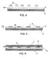
Fig. 4 shows a second step of an embodiment of the method; -
Fig. 5 shows a third step of an embodiment of the method; -
Fig. 6 shows a fourth step of an embodiment of the method; -
Fig. 7 shows a fifth step of an embodiment of the method; -
Fig. 8 is similar toFig. 6 and shows an alternative third step; -
Fig. 9 is similar toFig. 7 and depicts an alternative fourth step; -
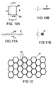
Fig. 10A shows a top view of a first embodiment of a spacer; -
Fig. 10B is a cross-section over line XB-XB ofFig. 10A ; -
Fig. 11A shows a top view of a second embodiment of a spacer; -
Fig. 11B is a cross-section over line XIB-XIB ofFig. 11A ; -
Fig. 12 is a top view of a spacer having apertures; -
Fig. 13 is similar toFig. 1 and shows an embodiment of a finger jointed composite element; -
Fig. 14 is a cross-section over line XIV-XIV ofFig. 13 ; and -
Fig. 15 schematically shows an embodiment of a positioning system for carrying out a process for joining moist parts. - Similar or corresponding features are denoted by similar or corresponding reference signs in this application.
-
Figures 1-2 schematically depict an embodiment of a composite element CE. The present element is made of a two parts (afirst part 1 and a second part 2), laminated together via aglue layer 3. According to a further embodiment (not depicted), a composite element CE can be made of more than two parts, wherein all the parts are joined via glue layers. - In the present embodiment, the
parts sheets Fig. 1 ), square, convex, concave, elongated, beam- or rodlike, and a combination of these and/or other shapes, as will be appreciated by the skilled person. - A composite structure CE provided by a process according to the invention can be used in an advantageous manner in/as construction element. The composite element CE can comprise or be used to provide, for instance, plate material, a wall, laminate, a sandwich construction, a construction block, a construction beam, a door, a window, a window casings, ceiling parts, board, a floor part, a roof box and/or the like.
- Also, each of the
parts parts - For example, the composite element CE is relatively large, made of relatively
large components 1, 2 (this contrary to, for example, composites that are made of fiber reinforced of wood chips material. As a non-limiting example, eachofparts parts - As is mentioned above, the
parts parts parts -
Figures 3-6 show an advantageous embodiment of joining twoparts figures 1-2 . The method preferably includes joining theparts bonding surfaces parts glue layer 3. According to a non-limiting embodiments, for example, theparts surfaces parts - The method can include an application of a
glue layer 3 to theparts 1, 2 (seeFig. 4 ). - Optionally, spacers (i.e. distance holders) 8 are provided between the
parts Fig. 5-6 . - After that, the
parts bonding surfaces 1a, 2b, with the bonding surfaces being spaced-apart from each other over the same distance T. - For example, the
parts Fig. 7 , by pressingdevices Fig. 15 ). - Also, preferably, the
moist parts glue 3, particularly by submerging theparts glue layer 3, thehardwood parts - More particularly, as has been mentioned, for example, the
parts unseasoned timer parts 1, 2 (i.e., freshly cut wood, having a high natural moist content), and/or in the case that theparts - Also, the method can comprise an actively wetting of the
parts Fig. 3 ), the method can include conditioning each of theparts hygroscopic parts parts parts parts - According to a further embodiment, the wood fibres of the
wood part parts moist parts parts - Depending on the wood type, the fiber saturation point is usually between 35 and 25%. When wood is in its fiber saturation point, wood cell walls are saturated with water, but in the cell cavities (the lumina), there is virtually no moisture yet. If the wood moisture content is higher than the fiber saturation point, the surplus of moisture is stored in the lumina, as free water. Generally, when wood moisture falls below the fiber saturation point, for example during a drying of the wood, the wood will shrink.
- According to an embodiment, the
bonding surfaces parts figures 6-7 ), wherein theglue 3 substantially contacts bothbonding surfaces glue 3 wets at least 50% of each of thebonding surfaces - Application of the
glue 3 can be achieved in various ways. For example,glue 3 can be applied to only one of the bonding surfaces 2a first, before theparts figures 4-7 ). For example,figure 4 depicts application of aglue layer 3 on thebonding surface 2a of asecond hardwood part 2. Alternatively, each of thebonding surfaces glue 3 first before joining theparts curable glue 3 is in a respective liquid or deformable state during application thereof. According to an embodiment, theglue 3 is applied onto themoist parts parts epoxy resin glue 3, and alternatively with acurable polyurethane adhesive 3. Additionally, theglue 3 as such can contain a hardener to promote the glue curing. - As is mentioned before, preferably, one or more (preferably loose, unbound)
spacers 8 are positioned between thebonding surfaces parts spacers 8 can be configured and applied in various ways. Thespacers 8 can be configured to hold theopposite bonding surfaces Fig. 7 ). Particularly, each of thespacers 8 is made of rigid material. Also, in the present embodiments, each of thespacers 8 has a thickness that equals a desired constant glue layer thickness T. - It has been found that good results are achieved when the mentioned glue layer (i.e. "glue line") thickness T is larger than 0.1 mm. For example, the layer thickness can be larger 0.2 mm, for example in the range of 0.2-2 mm. In a further embodiment, the glue layer thickness T in the range of 0.3-0.7 mm, for example in the range of 0.4-0.6 mm. It has been found that such layer thicknesses lead to highly reproducible, strong and durable bonds that can withstand various (particularly wet) moisture conditions.
-
Figure 5 depicts a step of applyingspacers 8 onto aglue layer 3 that is already applied onto thesecond part 2. Subsequently (seeFig. 6 ), thefirst part 1 can be positioned with itsbonding surface 1a onto theglue layer 3 andspacers 8, to be pressed towards the second part 2 (as inFig. 7 ), such that thespacers 8 are pressed onto theglue 3 to contact bothbonding surfaces surfaces bonding surface 1a, 1b of amoist part glue layer 3 can be applied onto thebonding surface parts more spacers 8 to thebonding surface other part - During curing of the
glue layer 3, for example, themoist parts Fig. 7 ) by pressingdevices Fig. 7 ), and for example using a pressure larger than about 0.5 N/mm2, for example a pressure in the range of 0.5 to 1.5 N/mm2, or a different pressure. Thepressing devices pressure application system bonding surfaces parts more spacers 8 can prevent that the pressing together of theparts glue 3. Thus, a highly reliable and durable bond can be obtained between theparts - Curing of the
glue layer 3 between themoist parts moist parts glue 3. For example, to this aim, theparts Fig. 7 ). The fluid W is schematically indicated inFigures 7, 9 by a dashed rectangle. For example the fluid W can be sprayed or merged onto theparts glue 3. Besides, for example, thepressing devices parts - After the curing process, for example, the
parts parts parts 1, 2 (so that the bondedparts parts parts - It has been found that the resulting composite hardwood element CE is strong, and can withstand wet and dry outdoors conditions and/or marine conditions for long periods of time. As is mentioned above, it is believed that the relatively thick, preferably initially stress-free,
bonding glue layer 3 can divert or absorb relatively large humidity related dimensional changes of thecomponents -
Figures 8-9 show an alternative, which differs from the embodiment ofFigures 6-7 , in that the spacers 8' are mixed with theglue 3 before theglue 3 is applied to at least one of theparts parts glue 3. For example, inFig. 9 , a pressing or positioning system 11', 12' is applied that can wet theparts moist parts - A
spacer 8 can have various shapes, for example flat, straight, curved, rectangular, square, convex, concave, elongated, beam- or rodlike, spherical, ellipsoid, and a combination of these and/or other shapes, as will be appreciated by the skilled person. Aspacer 8 can be hollow, or solid. According to an embodiment, a spacer as such comprises one or more apertures. - As is mentioned above, a
spacer 8 can be made of various materials, for example the same material as one or each of the parts that are to be bonded together, or a different material. Aspacer 8 as such can be made of wood, hardwood, or plastic, metal, an alloy, a fibre reinforced material, a composite material carbon fibre composite material, or another material. Preferably, allspacers 8, to be applied in joining theparts bonding surfaces -
Figures 10-12 show several non-limiting examples ofspacers 8, to be used in a method according to the invention. As mentioned above, eachspacer 8 can have a predetermined thickness T to provided a desired glue layer thickness, and is preferably made of rigid (i.e., inelastic) material that does not deform during the pressing together of theparts Fig. 10A, 10B , thespacer 8 is aflat platelet 8, of a small length x2 and a small width y2. For example, these dimensions x2, y2 can be a fraction of the length and width of theparts spacer 8 can be at most 1/10 the length x1 and width y1, respectively, of theparts parts spacer 8 can have roundededges 8a.Figures 11A, 11B show an embodiment of an elongated, cylindrical spacer 8', for example having a circular cross-section. -
Figure 12 shows yet another spacer embodiment. In this case, thespacer 8" is a relatively thin structure, for example a mat or sheet, comprising a plurality of apertures orcells 8u that can receive toglue 3 to bond theparts parts single spacer 8" can be applied between theparts - In the above embodiments, the
parts Figures 13-14 show an alternative configuration, wherein two parts 1', 2' have been joined by a method according to the invention, by finger jointing the parts 1', 2' together, to manufacture a composite element CE'. Also in this case, spaced-apart bonding surfaces of the parts 1', 2' (particularly of between the finger joint sections thereof) have been usingglue 3. -
Figure 15 depicts a non-limiting example of a (preferably automated)positioning system 20 that is configured to hold or support themoist parts parts moist parts system 20 can include twosupports parts system 20 can move thesupports system 20 can include aglue application device 29 that is configured to apply a relatively thick layer of curable glue to thebonding surfaces surfaces parts spacers 8. However, alternatively, the system carries out a method according to the invention without the application of spacers between theparts bonding surfaces 1a, 1b. Preferably, as above, thesystem 20 is also configured to prevent drying of themoist parts glue layer 3, for example by application of a fluid bath or fluid applicators to moisten theparts - Embodiments of the present invention lead to a reliable bonding of
moist parts parts - For example, it has been found that the method provides very good results in case of joining hardwood.
- In an experiment, flat Maçaranduba and Azobé samples of 100x100x20 mm3 have been prepared, from timber that was conditioned in a climate chamber at 97% Relative Humidity during at least 2 months. The obtained wood samples have been glued on the largest transversal side with grain direction of both samples parallel, by a process according to the invention, using spacers to provide a substantially tension free glue line, and were subsequently cured. After curing for 24 hours, the glued composite samples were cut into smaller samples, to obtain sample-parts of 50x50x40 mm3 each. Various curing conditions have been applied, including submerging the samples into hot water. The cured sample-parts were dried at 20 °C and 50% Relative Humidity for 14 days. After this drying period, the glue line of each sample-part was visually inspected for delamination. The sample-parts were also submersed in water at room temperature (20 °C) for 24 hours, prior to mechanical testing. The mechanical testing consisted of a shear test, similar to the shear test described in EN 392.
- In an experiment, a glue line thickness T of 0.5 mm, of SP 370 Epoxy resin, has applied between Azobé and
Maçaranduba samples - This resulted in a maximum shear strength (τ) of 9.221 MPa in case of the Azobé sample, and a maximum shear strength (τ) of 5.320 MPa in case of the Maçaranduba sample.
- In a further experiment, a glue line thickness T of 0.5 mm has applied between moist Azobé and
Maçaranduba samples - Also, experiments have been carried out using glue line thicknesses T significantly smaller than 0.1 mm (near zero thickness), and glue lines of 0.25 and 1.0 mm thick. It has been found that very thin glue lines (i.e., when pressing the wood parts together without using spacers 8) lead to unpredictable results. It has been found that glue lines of 0.25 mm thickness perform better than the near-zero thick glue lines. In the present experiments, the 1.0 thick glue lines have been found to perform in the same order of magnitude as the 0.5 mm thick glue lines, but can show some bubble formation under certain processes. Thus, (unstressed)
glue lines 3 having a thickness of about 0.5 mm have found to provide very good results (at least for certain wood types), to connect wet high density (tropical) hardwood parts. However, it is believed that glue lines with a thickness larger than 0.5 mm (for example in the range of 0.5-1.6 mm) can also provide good results. - It is to be understood that in the present application, the term "comprising" does not exclude other elements or steps. Also, each of the terms "a" and "an" does not exclude a plurality. Any reference sign(s) in the claims shall not be construed as limiting the scope of the claims.
- The term "part" should be interpreted broadly, since it can mean an element, building element, construction component and/or another part to be joined.
- For example, the method can include connecting two parts to form a composite element CE, or more than two parts. In case the element CE, to be manufactured, contains more than two parts, for example, the method can include joining the parts when they are all moist, wherein spaced-apart bonding surfaces are provided between all the parts, to be connected using a respective glue layer. Besides, a method for joining a plurality of parts can involve a sequence of gluing two parts to provide a composite element, and subsequently gluing a further part to the resulting composite element, until a desired number of parts has been joined together.
Claims (26)
- A method for joining moist parts, for example moist wood parts, wherein spaced-apart bonding surfaces of the parts are connected using a glue.
- The method according to claim 1, wherein the bonding surfaces are solid, uninterrupted glue receiving surfaces of the parts, that are faced towards each other, wherein the glue substantially contacts both bonding surfaces.
- The method according to claim 1 or 2, wherein the glue wets at least 50% of each of the bonding surfaces, preferably at least 75% and more preferably eat least 90%.
- The method according to any of the preceding claims, including: positioning one or more spacers (8) between the bonding surfaces (1a, 2a) of the parts (1, 2) to define or uphold a glue receiving space between the surfaces.
- The method according to claim 4, wherein a plurality of spacers (8) are mixed with the glue before the glue is applied to the parts (1, 2).
- The method according to claim 4 or 5, wherein the spacers (8) are configured to hold opposite bonding surfaces (1a, 2a) in parallel, and at a constant distance from each other during curing of the glue.
- The method according to any of the preceding claims, comprising providing a glue layer (3) having a thickness (T) larger than 0.1 mm, preferably larger than 0.2 mm, for example in the range of 0.2-2 mm, between the bonding surfaces, wherein the glue layer thickness is preferably in the range of 0.3-0.7 mm, more preferably in the range of 0.4-0.6 mm, wherein most preferably said glue layer thickness (T) is constant.
- The method according to any of claims 4-6 in combination with claim 7, wherein the one or more spacers (8) is/are made of rigid material and has a thickness that equals a desired glue layer thickness (T).
- The method according to any of the preceding claims, including pressing the moist parts (1, 2) together, particularly in directions normal with respect to an intermediate glue layer, during a curing of the glue (3), preferably using a pressure larger than about 0.5 N/mm2.
- The method according to claim 9 in combination with any of claims 4-6, 8, wherein the one or more spacers (8) is/are configured to prevent that the pressing together of the parts (1, 2) leads to tension in the glue.
- The method according to any of the preceding claims, wherein the moist parts (1, 2) are thermally treated to cure the glue, by submerging the parts (1,2) in hot fluid, preferably hot water (W).
- The method according to claim 11, wherein the parts (1, 2) are cooled after the thermal treatment, using a cooling liquid, for example water.
- The method according to any of the preceding claims, wherein at least one of the moist parts (1, 2) measures at least 1 cm along a first orthogonal direction (X), at least 1 cm along a second orthogonal direction (Y), and at least 1 mm along a third orthogonal direction (Z).
- The method according to any of the preceding claims, wherein the glue is applied onto the moist parts (1, 2), such that the glue does not penetrate the parts (1, 2)
- The method according to any of the preceding claims, wherein the glue is or contains a curable epoxy resin.
- The method according to any of the preceding claims, wherein the glue is or contains a curable polyurethane adhesive, or is one of: a phenol formaldehyde type, a resorcinol formaldehyde, and a phenolresorcinol formaldehyde type glue.
- The method according to any of the preceding claims, wherein at least one of the moist parts (1, 2) is made of: concrete, stone, brick, or ceramics.
- The method according to any of the preceding claims, comprising: wetting the parts (1, 2) with water before application of the glue (3) to the parts (1, 2).
- The method according to any of the preceding claims, wherein at least one of the moist parts is made of freshly cut wood.
- The method according to any of the preceding claims, including laminating or finger jointing the parts (1, 2) together.
- The method according to any of the preceding claims, wherein at least one of the moist parts is a wood part, wherein the wood fibers of the wood part (1, 2) are substantially saturated with water, before the parts are connected to each other using the glue.
- The method according to any of the preceding claims, wherein at least one of the moist parts (1, 2) is made of wood, particularly hardwood, for example at least one of: oak, beech, elm, maple, tropical hardwood, meranti, wenge, walnut, teak, mahogany, azobe, maçaranduba, and ebony, and/or has a dry wood density of at least 800 kg/m3.
- The method according to any of the preceding claims, wherein the moist parts (1, 2) are made of the same material.
- A method for joining moist hardwood parts, for example a method according to any of the preceding claims, wherein bonding surfaces of the hardwood parts are connected using a glue.
- The method according to claim 24, wherein a glue line having a thickness of more than 0.1 mm is applied between the bonding surfaces, and preferably a glue line having a thickness in the range of 0.2 mm - 2 mm
- A composite element (CE), manufactured by a method according to any of the preceding claims.
Priority Applications (4)
| Application Number | Priority Date | Filing Date | Title |
|---|---|---|---|
| EP07076099A EP2072593A1 (en) | 2007-12-18 | 2007-12-18 | A method for joining moist parts |
| BRPI0821014-4A BRPI0821014A2 (en) | 2007-12-18 | 2008-12-17 | Method for joining wetted parts and composite element |
| EP08862958A EP2235125A1 (en) | 2007-12-18 | 2008-12-17 | A method for joining moist parts |
| PCT/NL2008/050807 WO2009078714A1 (en) | 2007-12-18 | 2008-12-17 | A method for joining moist parts |
Applications Claiming Priority (1)
| Application Number | Priority Date | Filing Date | Title |
|---|---|---|---|
| EP07076099A EP2072593A1 (en) | 2007-12-18 | 2007-12-18 | A method for joining moist parts |
Publications (1)
| Publication Number | Publication Date |
|---|---|
| EP2072593A1 true EP2072593A1 (en) | 2009-06-24 |
Family
ID=39387175
Family Applications (2)
| Application Number | Title | Priority Date | Filing Date |
|---|---|---|---|
| EP07076099A Withdrawn EP2072593A1 (en) | 2007-12-18 | 2007-12-18 | A method for joining moist parts |
| EP08862958A Withdrawn EP2235125A1 (en) | 2007-12-18 | 2008-12-17 | A method for joining moist parts |
Family Applications After (1)
| Application Number | Title | Priority Date | Filing Date |
|---|---|---|---|
| EP08862958A Withdrawn EP2235125A1 (en) | 2007-12-18 | 2008-12-17 | A method for joining moist parts |
Country Status (3)
| Country | Link |
|---|---|
| EP (2) | EP2072593A1 (en) |
| BR (1) | BRPI0821014A2 (en) |
| WO (1) | WO2009078714A1 (en) |
Cited By (2)
| Publication number | Priority date | Publication date | Assignee | Title |
|---|---|---|---|---|
| WO2013033736A3 (en) * | 2011-09-02 | 2013-06-13 | Spencer Drake Trust (It 8663/95) | Construction timber |
| US20170037205A1 (en) * | 2015-08-04 | 2017-02-09 | Binderholz International AG | Unknown |
Citations (9)
| Publication number | Priority date | Publication date | Assignee | Title |
|---|---|---|---|---|
| WO1986001142A1 (en) * | 1984-08-17 | 1986-02-27 | Kallenmäki Oy | A method of fixing a wooden sheet of veneer to a supporting lamina |
| EP0320803A2 (en) * | 1987-12-17 | 1989-06-21 | Pavatex Ag | Three-dimensional wooden work piece for use as a structural component |
| EP0493010A1 (en) | 1990-12-21 | 1992-07-01 | Her Majesty The Queen In Right Of New Zealand, Acting By And Through The Secretary Of Forestry | Method of joining wood |
| JPH04298583A (en) * | 1991-03-28 | 1992-10-22 | Sharp Corp | Bonding structure and bonding method |
| US5232962A (en) * | 1991-10-09 | 1993-08-03 | Quantum Materials, Inc. | Adhesive bonding composition with bond line limiting spacer system |
| US5804019A (en) * | 1997-01-31 | 1998-09-08 | Triangle Pacific Corporation | Apparatus and method for applying adhesive and release paper to wooden flooring strips |
| US20010027828A1 (en) * | 2000-04-05 | 2001-10-11 | Hodgskiss Malcolm Gibson | Mobile wood joinery |
| DE102005023102A1 (en) * | 2005-05-13 | 2006-11-16 | Unaxis Balzers Ag | Structured gluing method e.g. for surfaces, involves making surface of body available, on which structured adhesive layer is to be applied with filter and blade provided |
| DE102005026815A1 (en) * | 2005-06-09 | 2006-12-21 | Ortwin Prof. Dr.-Ing. Hahn | Adhesive bonding for connecting two laminar vehicle parts, comprises applying adhesive between the oppositely facing connection surfaces of the parts to form sticking seam, and embedding a heatable metallic element in the adhesive |
Family Cites Families (1)
| Publication number | Priority date | Publication date | Assignee | Title |
|---|---|---|---|---|
| GB1412903A (en) * | 1972-07-18 | 1975-11-05 | Dantani Plywood Co | Process for producing sliced veneer and fancy plywood therefrom |
-
2007
- 2007-12-18 EP EP07076099A patent/EP2072593A1/en not_active Withdrawn
-
2008
- 2008-12-17 WO PCT/NL2008/050807 patent/WO2009078714A1/en not_active Ceased
- 2008-12-17 EP EP08862958A patent/EP2235125A1/en not_active Withdrawn
- 2008-12-17 BR BRPI0821014-4A patent/BRPI0821014A2/en not_active IP Right Cessation
Patent Citations (9)
| Publication number | Priority date | Publication date | Assignee | Title |
|---|---|---|---|---|
| WO1986001142A1 (en) * | 1984-08-17 | 1986-02-27 | Kallenmäki Oy | A method of fixing a wooden sheet of veneer to a supporting lamina |
| EP0320803A2 (en) * | 1987-12-17 | 1989-06-21 | Pavatex Ag | Three-dimensional wooden work piece for use as a structural component |
| EP0493010A1 (en) | 1990-12-21 | 1992-07-01 | Her Majesty The Queen In Right Of New Zealand, Acting By And Through The Secretary Of Forestry | Method of joining wood |
| JPH04298583A (en) * | 1991-03-28 | 1992-10-22 | Sharp Corp | Bonding structure and bonding method |
| US5232962A (en) * | 1991-10-09 | 1993-08-03 | Quantum Materials, Inc. | Adhesive bonding composition with bond line limiting spacer system |
| US5804019A (en) * | 1997-01-31 | 1998-09-08 | Triangle Pacific Corporation | Apparatus and method for applying adhesive and release paper to wooden flooring strips |
| US20010027828A1 (en) * | 2000-04-05 | 2001-10-11 | Hodgskiss Malcolm Gibson | Mobile wood joinery |
| DE102005023102A1 (en) * | 2005-05-13 | 2006-11-16 | Unaxis Balzers Ag | Structured gluing method e.g. for surfaces, involves making surface of body available, on which structured adhesive layer is to be applied with filter and blade provided |
| DE102005026815A1 (en) * | 2005-06-09 | 2006-12-21 | Ortwin Prof. Dr.-Ing. Hahn | Adhesive bonding for connecting two laminar vehicle parts, comprises applying adhesive between the oppositely facing connection surfaces of the parts to form sticking seam, and embedding a heatable metallic element in the adhesive |
Cited By (6)
| Publication number | Priority date | Publication date | Assignee | Title |
|---|---|---|---|---|
| WO2013033736A3 (en) * | 2011-09-02 | 2013-06-13 | Spencer Drake Trust (It 8663/95) | Construction timber |
| CN104023924A (en) * | 2011-09-02 | 2014-09-03 | 斯潘塞德雷克信托基金会 | Construction timber |
| EP2750843A4 (en) * | 2011-09-02 | 2015-05-06 | Spencer Drake Trust It 8663 95 | Construction timber |
| US9393714B2 (en) | 2011-09-02 | 2016-07-19 | Spencer Drake Trust (It 8663/95) | Construction timber |
| AU2012301542B2 (en) * | 2011-09-02 | 2016-10-27 | Biligom International (Pty) Ltd | Construction timber |
| US20170037205A1 (en) * | 2015-08-04 | 2017-02-09 | Binderholz International AG | Unknown |
Also Published As
| Publication number | Publication date |
|---|---|
| WO2009078714A1 (en) | 2009-06-25 |
| EP2235125A1 (en) | 2010-10-06 |
| BRPI0821014A2 (en) | 2015-06-16 |
Similar Documents
| Publication | Publication Date | Title |
|---|---|---|
| ES2780178T3 (en) | Wood veneer multilayer patterned body | |
| US8011165B2 (en) | Composite assembly with saturated bonding mass and process of reinforced attachment | |
| US20170210098A1 (en) | Permeable elastomeric membrane adhered to fire-rated structural osb panels | |
| CN109863274A (en) | Foam wall structure and method for its manufacture | |
| US6281148B1 (en) | Resin starved impregnated panels, wood composites utilizing said panels and methods of making the same | |
| US20080282632A1 (en) | Composite building panel | |
| SE521525C2 (en) | Panels utilizing a pre-cured reinforced core and method for manufacturing the same | |
| US7770342B2 (en) | Hollow core floor and deck element | |
| CZ2003131A3 (en) | Self-supporting building element, its use and process for preparing thereof | |
| EP2316624A2 (en) | Multi-layer wood panel | |
| CN102990730B (en) | Glued wood component with controllable dimensional stability and preparation method thereof | |
| WO2013026172A1 (en) | Construction board with defined air permeability | |
| DK2351635T3 (en) | End tree body with balsa wood and method for its preparation | |
| AU647769B2 (en) | Methods for manufacturing composite surface elements | |
| EP2644478B1 (en) | Plywood Panel | |
| CN108162519B (en) | Longitudinal reinforced orthogonal laminated wood and manufacturing method thereof | |
| WO2009078714A1 (en) | A method for joining moist parts | |
| US9724874B2 (en) | Method for splicing stress skins used for manufacturing structural insulated panels | |
| RU2007117349A (en) | COMBINED PLATE FOR FIRE DOORS | |
| CN111645394A (en) | Composite material laminated board and preparation method thereof | |
| KR20160125655A (en) | Manufacturing Method of Cross Laminated Timber And Its Products | |
| JP6726991B2 (en) | Heat storage panel | |
| RU143311U1 (en) | COMPOSITE CONSTRUCTION BEAM (OPTIONS) | |
| JP7291285B1 (en) | Underfloor material and floor structure | |
| FI57640C (en) | FOERFARANDE FOER FRAMSTAELLNING AV YTBAERANDE BYGGELEMENT FOERETRAEDESVIS BYGGBLOCK |
Legal Events
| Date | Code | Title | Description |
|---|---|---|---|
| PUAI | Public reference made under article 153(3) epc to a published international application that has entered the european phase |
Free format text: ORIGINAL CODE: 0009012 |
|
| AK | Designated contracting states |
Kind code of ref document: A1 Designated state(s): AT BE BG CH CY CZ DE DK EE ES FI FR GB GR HU IE IS IT LI LT LU LV MC MT NL PL PT RO SE SI SK TR |
|
| AX | Request for extension of the european patent |
Extension state: AL BA HR MK RS |
|
| 17P | Request for examination filed |
Effective date: 20091228 |
|
| AKX | Designation fees paid |
Designated state(s): AT BE BG CH CY CZ DE DK EE ES FI FR GB GR HU IE IS IT LI LT LU LV MC MT NL PL PT RO SE SI SK TR |
|
| 17Q | First examination report despatched |
Effective date: 20100311 |
|
| D17P | Request for examination filed (deleted) | ||
| REG | Reference to a national code |
Ref country code: DE Ref legal event code: 8566 |
|
| STAA | Information on the status of an ep patent application or granted ep patent |
Free format text: STATUS: THE APPLICATION IS DEEMED TO BE WITHDRAWN |
|
| 18D | Application deemed to be withdrawn |
Effective date: 20091225 |