EP2072309A1 - Electric automobile - Google Patents
Electric automobile Download PDFInfo
- Publication number
- EP2072309A1 EP2072309A1 EP08721415A EP08721415A EP2072309A1 EP 2072309 A1 EP2072309 A1 EP 2072309A1 EP 08721415 A EP08721415 A EP 08721415A EP 08721415 A EP08721415 A EP 08721415A EP 2072309 A1 EP2072309 A1 EP 2072309A1
- Authority
- EP
- European Patent Office
- Prior art keywords
- members
- battery case
- battery
- electromagnetic shield
- battery unit
- Prior art date
- Legal status (The legal status is an assumption and is not a legal conclusion. Google has not performed a legal analysis and makes no representation as to the accuracy of the status listed.)
- Granted
Links
Images

Classifications
-
- B—PERFORMING OPERATIONS; TRANSPORTING
- B60—VEHICLES IN GENERAL
- B60K—ARRANGEMENT OR MOUNTING OF PROPULSION UNITS OR OF TRANSMISSIONS IN VEHICLES; ARRANGEMENT OR MOUNTING OF PLURAL DIVERSE PRIME-MOVERS IN VEHICLES; AUXILIARY DRIVES FOR VEHICLES; INSTRUMENTATION OR DASHBOARDS FOR VEHICLES; ARRANGEMENTS IN CONNECTION WITH COOLING, AIR INTAKE, GAS EXHAUST OR FUEL SUPPLY OF PROPULSION UNITS IN VEHICLES
- B60K1/00—Arrangement or mounting of electrical propulsion units
- B60K1/04—Arrangement or mounting of electrical propulsion units of the electric storage means for propulsion
-
- B—PERFORMING OPERATIONS; TRANSPORTING
- B60—VEHICLES IN GENERAL
- B60L—PROPULSION OF ELECTRICALLY-PROPELLED VEHICLES; SUPPLYING ELECTRIC POWER FOR AUXILIARY EQUIPMENT OF ELECTRICALLY-PROPELLED VEHICLES; ELECTRODYNAMIC BRAKE SYSTEMS FOR VEHICLES IN GENERAL; MAGNETIC SUSPENSION OR LEVITATION FOR VEHICLES; MONITORING OPERATING VARIABLES OF ELECTRICALLY-PROPELLED VEHICLES; ELECTRIC SAFETY DEVICES FOR ELECTRICALLY-PROPELLED VEHICLES
- B60L50/00—Electric propulsion with power supplied within the vehicle
- B60L50/50—Electric propulsion with power supplied within the vehicle using propulsion power supplied by batteries or fuel cells
- B60L50/60—Electric propulsion with power supplied within the vehicle using propulsion power supplied by batteries or fuel cells using power supplied by batteries
- B60L50/64—Constructional details of batteries specially adapted for electric vehicles
-
- B—PERFORMING OPERATIONS; TRANSPORTING
- B60—VEHICLES IN GENERAL
- B60L—PROPULSION OF ELECTRICALLY-PROPELLED VEHICLES; SUPPLYING ELECTRIC POWER FOR AUXILIARY EQUIPMENT OF ELECTRICALLY-PROPELLED VEHICLES; ELECTRODYNAMIC BRAKE SYSTEMS FOR VEHICLES IN GENERAL; MAGNETIC SUSPENSION OR LEVITATION FOR VEHICLES; MONITORING OPERATING VARIABLES OF ELECTRICALLY-PROPELLED VEHICLES; ELECTRIC SAFETY DEVICES FOR ELECTRICALLY-PROPELLED VEHICLES
- B60L50/00—Electric propulsion with power supplied within the vehicle
- B60L50/50—Electric propulsion with power supplied within the vehicle using propulsion power supplied by batteries or fuel cells
- B60L50/60—Electric propulsion with power supplied within the vehicle using propulsion power supplied by batteries or fuel cells using power supplied by batteries
- B60L50/66—Arrangements of batteries
-
- H—ELECTRICITY
- H01—ELECTRIC ELEMENTS
- H01M—PROCESSES OR MEANS, e.g. BATTERIES, FOR THE DIRECT CONVERSION OF CHEMICAL ENERGY INTO ELECTRICAL ENERGY
- H01M50/00—Constructional details or processes of manufacture of the non-active parts of electrochemical cells other than fuel cells, e.g. hybrid cells
- H01M50/20—Mountings; Secondary casings or frames; Racks, modules or packs; Suspension devices; Shock absorbers; Transport or carrying devices; Holders
- H01M50/202—Casings or frames around the primary casing of a single cell or a single battery
-
- H—ELECTRICITY
- H01—ELECTRIC ELEMENTS
- H01M—PROCESSES OR MEANS, e.g. BATTERIES, FOR THE DIRECT CONVERSION OF CHEMICAL ENERGY INTO ELECTRICAL ENERGY
- H01M50/00—Constructional details or processes of manufacture of the non-active parts of electrochemical cells other than fuel cells, e.g. hybrid cells
- H01M50/20—Mountings; Secondary casings or frames; Racks, modules or packs; Suspension devices; Shock absorbers; Transport or carrying devices; Holders
- H01M50/244—Secondary casings; Racks; Suspension devices; Carrying devices; Holders characterised by their mounting method
-
- H—ELECTRICITY
- H01—ELECTRIC ELEMENTS
- H01M—PROCESSES OR MEANS, e.g. BATTERIES, FOR THE DIRECT CONVERSION OF CHEMICAL ENERGY INTO ELECTRICAL ENERGY
- H01M50/00—Constructional details or processes of manufacture of the non-active parts of electrochemical cells other than fuel cells, e.g. hybrid cells
- H01M50/20—Mountings; Secondary casings or frames; Racks, modules or packs; Suspension devices; Shock absorbers; Transport or carrying devices; Holders
- H01M50/249—Mountings; Secondary casings or frames; Racks, modules or packs; Suspension devices; Shock absorbers; Transport or carrying devices; Holders specially adapted for aircraft or vehicles, e.g. cars or trains
-
- H—ELECTRICITY
- H05—ELECTRIC TECHNIQUES NOT OTHERWISE PROVIDED FOR
- H05K—PRINTED CIRCUITS; CASINGS OR CONSTRUCTIONAL DETAILS OF ELECTRIC APPARATUS; MANUFACTURE OF ASSEMBLAGES OF ELECTRICAL COMPONENTS
- H05K9/00—Screening of apparatus or components against electric or magnetic fields
- H05K9/0007—Casings
- H05K9/002—Casings with localised screening
-
- B—PERFORMING OPERATIONS; TRANSPORTING
- B60—VEHICLES IN GENERAL
- B60K—ARRANGEMENT OR MOUNTING OF PROPULSION UNITS OR OF TRANSMISSIONS IN VEHICLES; ARRANGEMENT OR MOUNTING OF PLURAL DIVERSE PRIME-MOVERS IN VEHICLES; AUXILIARY DRIVES FOR VEHICLES; INSTRUMENTATION OR DASHBOARDS FOR VEHICLES; ARRANGEMENTS IN CONNECTION WITH COOLING, AIR INTAKE, GAS EXHAUST OR FUEL SUPPLY OF PROPULSION UNITS IN VEHICLES
- B60K1/00—Arrangement or mounting of electrical propulsion units
- B60K1/04—Arrangement or mounting of electrical propulsion units of the electric storage means for propulsion
- B60K2001/0405—Arrangement or mounting of electrical propulsion units of the electric storage means for propulsion characterised by their position
- B60K2001/0438—Arrangement under the floor
-
- Y—GENERAL TAGGING OF NEW TECHNOLOGICAL DEVELOPMENTS; GENERAL TAGGING OF CROSS-SECTIONAL TECHNOLOGIES SPANNING OVER SEVERAL SECTIONS OF THE IPC; TECHNICAL SUBJECTS COVERED BY FORMER USPC CROSS-REFERENCE ART COLLECTIONS [XRACs] AND DIGESTS
- Y02—TECHNOLOGIES OR APPLICATIONS FOR MITIGATION OR ADAPTATION AGAINST CLIMATE CHANGE
- Y02E—REDUCTION OF GREENHOUSE GAS [GHG] EMISSIONS, RELATED TO ENERGY GENERATION, TRANSMISSION OR DISTRIBUTION
- Y02E60/00—Enabling technologies; Technologies with a potential or indirect contribution to GHG emissions mitigation
- Y02E60/10—Energy storage using batteries
-
- Y—GENERAL TAGGING OF NEW TECHNOLOGICAL DEVELOPMENTS; GENERAL TAGGING OF CROSS-SECTIONAL TECHNOLOGIES SPANNING OVER SEVERAL SECTIONS OF THE IPC; TECHNICAL SUBJECTS COVERED BY FORMER USPC CROSS-REFERENCE ART COLLECTIONS [XRACs] AND DIGESTS
- Y02—TECHNOLOGIES OR APPLICATIONS FOR MITIGATION OR ADAPTATION AGAINST CLIMATE CHANGE
- Y02T—CLIMATE CHANGE MITIGATION TECHNOLOGIES RELATED TO TRANSPORTATION
- Y02T10/00—Road transport of goods or passengers
- Y02T10/60—Other road transportation technologies with climate change mitigation effect
- Y02T10/70—Energy storage systems for electromobility, e.g. batteries
Definitions
- the present invention relates to an electric vehicle which runs by means of a motor using a battery as a power source.
- an electromagnetic wave is generated from, for example, the motor, current control circuit or the like.
- an electromagnetic shield means be provided for electric components which might be adversely affected by an electromagnetic wave or electric equipments which might be electromagnetic wave generation sources.
- an electromagnetic shield means for a battery case is described.
- paint for electromagnetic shield having an effect of reflecting an electromagnetic wave is applied to a surface of the battery case.
- a process for applying the paint, process for drying the applied paint, and the like are required, in addition to that the paint for electromagnetic shield itself is expensive. For this reason, the electromagnetic shield means not only takes a lot of time, but also requires great expenses.
- the paint for electromagnetic shield is applied only to a part of the battery case around an electric component to be shielded inside the battery case.
- an electromagnetic shield member such as an iron plate is arranged inside the battery case.
- providing a conductive member in the small space inside the battery case is not desirable because a factor for causing an electric short circuit is provided.
- the present invention provides an electric vehicle in which a battery unit mounted on the vehicle body can be shielded against an electromagnetic wave in a relatively simple and easy manner.
- An electric vehicle of the present invention comprises a frame structure including a pair of right and left side members made of metal, arranged at a lower part of a vehicle body, a floor panel made of metal provided on the frame structure, a battery unit including a battery case arranged between the pair of side members on the undersurface side of the floor panel, the battery case containing therein battery modules and electric components electrically connected to the battery modules, and the upper side of the electric components being electromagnetically shielded by the floor panel, a front electromagnetic shield portion arranged on the vehicle-front side with respect to the electric components, a rear electromagnetic shield portion arranged on the vehicle-rear side with respect to the electric components, and an under electromagnetic shield portion arranged on the undersurface side of the battery case.
- the present invention it is possible to prevent electric components contained in the battery unit and the like arranged under the floor panel of the electric vehicle from being adversely affected by an electromagnetic wave. Further, it is also possible to prevent an electromagnetic wave generated from the battery unit from adversely affecting the neighboring electric components and the like.
- each of the front electromagnetic shield portion and the rear electromagnetic shield portion is constituted of an insert member made of metal embedded in the resin constituting the battery case.
- an under cover for covering the battery case from below may be arranged below the battery case, and the under electromagnetic shield portion may be constituted of a shield member provided on the under cover.
- beam members made of metal extending in the width direction of the vehicle body are provided under the battery case, both end portions of the beam members are supported by the pair of side members, the under electromagnetic shield portion is constituted of the beam members, and portions overlapping the beam members made of metal when viewed from above the vehicle body may not be provided with the shield member of the under cover.
- FIGS. 1 to 7 An embodiment of the present invention will be described below with reference to FIGS. 1 to 7 .
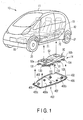
- FIG. 1 shows an example of an electric vehicle 10.
- This electric vehicle 10 is provided with a motor 12 for traveling, and charging equipment 13 which are arranged at the rear part of the vehicle body 11, a battery unit 14 arranged under the floor of the vehicle body 11, and the like.
- a heat exchanger unit 15 for air-conditioning is arranged at the front part of the vehicle body 11.
- the front wheels 20 of the vehicle 10 are supported by the vehicle body 11 by means of front suspensions (not shown).
- the rear wheels 21 are supported by the vehicle body 11 by means of rear suspensions (not shown).
- An example of the rear suspension is a trailing arm type rear suspension.
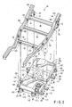
- FIG. 2 shows a frame structure 30 constituting a lower skeletal structure of the vehicle body 11, and the battery unit 14 to be attached to the frame structure 30.
- the frame structure 30 includes a pair of right and left side members 31 and 32 extending in the back-and-forth direction of the vehicle body 11, and cross members 33, 34, and 35 extending in the width direction of the vehicle body 11.
- the cross members 33, 34, and 35 are fixed to predetermined positions of the side members 31 and 32 by welding.
- Each of the side members 31 and 32, and cross members 33, 34, and 35 is constituted of metal (for example, steel). That is, the side members 31 and 32 also function as an electromagnetic shield portion for intercepting electromagnetic waves from both the right and left sides of the battery unit 14.
- Suspension arm support brackets 40 and 41 are provided at the rear parts of the side members 31 and 32. Each of the suspension arm support brackets 40 and 41 is fixed to a predetermined position of each of the side members 31 and 32 by welding. Each of the suspension arm support brackets 40 and 41 is provided with an axis section 42. Front end parts of the trailing arms are attached to these axis sections 42.
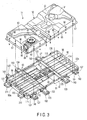
- the battery unit 14 is provided with a battery case 50.
- the battery case 50 includes a tray member 51 positioned on the lower side, and a cover member 52 positioned on the upper side.
- a front battery containing section 55 is formed at the front half part of the battery case 50.
- a rear battery containing section 56 is formed at the rear half part of the battery case 50.
- a center battery containing section 57, an electric circuit containing section 58, and the like are formed between the front battery containing section 55 and rear battery containing section 56.
- a battery module 60 (only part thereof is shown by two-dot chain lines in FIG. 3 ) is contained in each of the battery containing sections 55, 56, and 57.
- An example of the battery module 60 is a battery module formed by connecting, in series, a plurality of cells each of which is constituted of a lithium ion battery.
- a monitor for detecting a state of the battery module 60, electric components 61 (part of them are schematically shown in FIGS. 3 and 7 ) and the like for managing control and the like are contained in the electric circuit containing section 58.
- the electric components 61 are electrically connected to the battery modules 60.
- the electric components 61 are provided with an electromagnetic shield means to be described later.
- the battery unit 14 is arranged on the undersurface side of a floor panel 70 made of steel, and having an electromagnetic shielding effect.
- the upper side of the electric components 61 is magnetically shielded by the floor panel 70. That is, the floor panel 70 also functions as an upper electromagnetic shield portion for intercepting an electromagnetic wave from above the battery unit 14. Further, the floor panel 70 also functions as a shield for preventing an electromagnetic wave generated from the battery unit 14 from being directed upward.
- the floor panel 70 extends in the back-and-forth direction and width direction of the vehicle body 11 to constitute a floor part of the vehicle body 11.
- the floor panel 70 is fixed to a predetermined position of the frame structure 30 including the side members 31 and 32 by welding. Front seats 71 (shown in FIG. 1 ) and rear seats 72 are arranged above the floor panel 70. The front battery containing section 55 of the battery unit 14 is arranged below the front seats 71. The rear battery containing section 56 of the battery unit 14 is arranged below the rear seats 72.
- the floor panel 70 includes a concave portion 70a.
- the concave portion 70a is formed between the front battery containing section 55 and rear battery containing section 56. This concave portion 70a is positioned in the vicinity of the feet of the occupants seated on the rear seats 72.
- the tray member 51 is a molded article formed by inserting metal insert members 200 (shown in FIG. 7 ) for reinforcement in an integrally molded synthetic resin member.
- This tray member 51 is formed into a box-like shape opened at its top surface.
- the synthetic resin which is the material of the tray member 51 is reinforced by, for example, fibers.
- a cover fitting surface 80 (shown in FIG. 3 ) is formed at a peripheral edge part of the top surface of the tray member 51.
- the cover fitting surface 80 is continuous over the whole circumference of the tray member 51.
- a waterproof seal member 81 is provided on the cover fitting surface 80.
- the insert members 200 includes three metal plates 200a, 200b, and 200c positioned on the front side of the tray member 51, and three metal plates 200d, 200e, and 200f positioned on the rear side of the tray member 51.
- These metal plates 200a to 200f are constituted of a metallic material having an electromagnetic shielding effect, and large bending rigidity, for example, a steel sheet.
- the metal plates 200a, 200b, and 200c which are positioned on the front side are embedded at positions corresponding to the front part, and right left sides of the front battery containing section 55.
- a pair of right and left reinforcement plates 201 extending rearward is provided at both ends of the metal plate 200a on the center-front side.
- These reinforcement plates 201 are provided inside the resin constituting partition walls 51a of the tray member 51.
- These metal plates 200a, 200b, and 200c have a function of reinforcing the peripheral wall of the tray member 51.
- the metal plate 200a on the center-front side functions also as a front electromagnetic shield portion positioned on the vehicle-front side with respect to the electric components 61.
- each of the metal plates 200a, 200b, and 200c is provided with embedded nuts 203 protruding in the horizontal direction, an anchor bolt 204 protruding upward, and nut portions 205 each of which is provided with a threaded hole.
- the metal plates 200d, 200e, and 200f on the rear side are embedded at positions corresponding to the rear part, and right left sides of the rear battery containing section 56 of the tray member 51.
- An anchor bolt 206 protruding upward, and nut portions 207 each of which is provided with a threaded hole are provided on a top surface of each of the metal plates 200d, 200e, and 200f.
- Embedded nuts 208 protruding in the horizontal direction are fixed to the pair of right and left metal plates 200e and 200f.
- These metal plates 200d, 200e, and 200f have a function of reinforcing the peripheral wall of the tray member 51.
- the metal plate 200d on the center-rear side functions also as a rear electromagnetic shield portion positioned on the vehicle-rear side with respect to the electric components 61.
- each of a front wall and rear wall of the battery case 50 may be provided with an electromagnetic shield member such as a metal mesh member in order to enhance the electromagnetic shielding effect at each of front and rear directions of the electric components 61.
- Each of right and left walls of the battery case 50 may also be provided with an electromagnetic shield member such as a metal mesh member in order to enhance the electromagnetic shielding effect at each of right and left areas of the battery case 50.
- the cover member 52 is constituted of an integrally molded product of a synthetic resin reinforced by fibers.
- An opening 85 for service plug and cooling air introduction opening 86 are formed at a front part of the cover member 52.
- a bellows-like boot 87 is attached to the opening 85 for service plug.
- a bellows-like boot 88 is also attached to the cooling air introduction opening 86.
- a bypass flow path 90 for causing part of the cooling air to flow therethrough, cooling fan containing section 91, and the like are provided on the top surface of the cover member 52.
- a flange portion 95 is formed at a peripheral edge part of the cover member 52.
- the flange portion 95 is continuous over the whole circumference of the cover member 52.
- a rear metal plate (not shown) made of metal serving as measures against a rear collision is arranged on the rear surface of the cover member 52. The rear metal plate is fixed to the tray member 51 together with the flange portion 95 of the cover member 52, and can function as a rear electromagnetic shield portion.
- the flange portion 95 of the cover member 52 is placed on the cover fitting surface 80 of the tray member 51. Further, the tray member 51 and cover member 52 are fixed to each other through the seal member 81 in a watertight manner by means of bolts 96 and nuts 97 shown in FIG. 3 .
- a plurality of (for example, four) beam members 101, 102, 103, and 104 are provided on the undersurface side of the tray member 51.
- the beam members 101, 102, 103, and 104 respectively include beam bodies 111, 112, 113, and 114 extending in the width direction of the vehicle body 11.
- the first beam body 111 from the front is provided with joining portions 121 and 122 at both ends thereof.
- the second beam body 112 from the front is provided with joining portions 123 and 124 at both ends thereof.
- the third beam body 113 from the front is provided with joining portions 125 and 126 at both ends thereof.
- the fourth (rearmost) beam body 114 from the front is provided with joining portions 127 and 128 at both ends thereof.
- a pair of right and left front support members 130 and 131 is provided at a front end part of the battery unit 14.
- the beam members 101, 102, 103, and 104 are each provided with strength sufficient to support the weight of the battery unit 14. Furthermore, these beam members are constituted of a metallic material (for example, a steel sheet) having an effect of intercepting an electromagnetic wave. That is, the beam members 101, 102, 103, and 104 function also as an under electromagnetic shield portion for intercepting an electromagnetic wave from below the battery unit 14.
- a bolt inserting hole 143 (shown in FIGS. 2 and 3 ) is formed in each of the joining portions 121 and 122 provided at both the ends of the first beam member 101 from the front.
- the bolt inserting hole 143 penetrates the joining portion 121 or 122 in the vertical direction.
- the side members 31 and 32 are provided with battery unit fitting portions 145 and 146 at positions opposed to the joining portions 121 and 122.
- the battery unit fitting portions 145 and 146 are provided with nut members.
- a bolt 147 (shown in FIGS. 2 and 4 ) is inserted into the bolt inserting hole 143 from below the joining portion 121 or 122.
- the bolt 147 is screwed into the nut member of the battery unit fitting portion 145 or 146 to be fastened.
- the joining portions 121 and 122 of the first beam member 101 are fixed to the side members 31 and 32.
- a bolt inserting hole 153 (shown in FIGS. 2 and 3 ) is formed in each of the joining portions 123 and 124 provided at both the ends of the second beam member 102 from the front.
- the bolt inserting hole 153 penetrates the joining portion 123 or 124 in the vertical direction.
- the side members 31 and 32 are provided with battery unit fitting portions 155 and 156 at positions opposed to the joining portions 123 and 124.
- the battery unit fitting portions 155 and 156 are provided with nut members.
- a bolt 157 (shown in FIGS. 2 and 4 ) is inserted into the bolt inserting hole 153 from below the joining portion 123 or 124.
- the bolt 157 is screwed into the nut member of the battery unit fitting portion 155 or 156 to be fastened.
- the joining portions 123 and 124 of the second beam member 102 are fixed to the side members 31 and 32.
- a bolt inserting hole 163 (shown in FIGS. 2 and 3 ) is formed in each of the joining portions 125 and 126 provided at both the ends of the third beam member 103 from the front.
- the bolt inserting hole 163 penetrates the joining portion 125 or 126 in the vertical direction.
- load transmission members 170 and 171 are fixed to the side members 31 and 32 by means of bolts 172.
- the load transmission members 170 and 171 are provided above the joining portions 125 and 126 of the third beam member 103 from the front.
- the one load transmission member 170 is welded to one suspension arm support bracket 40.
- the other load transmission member 171 is welded to the other suspension arm support bracket 41.
- load transmission members 170 and 171 are joined to the side members 31 and 32, and suspension arm support brackets 40 and 41. These load transmission members 170 and 171 constitute part of the frame structure 30.
- the load transmission members 170 and 171 are provided with battery unit fitting portions 175 and 176 including nut members.
- a bolt 177 is inserted into the bolt inserting hole 163 from below the joining portion 125 or 126.
- the bolt 177 is screwed into the nut member of the battery unit fitting portion 175 or 176 to be fastened.
- the joining portions 125 and 126 of the third beam member 103 are fixed to the side members 31 and 32 through the load transmission members 170 and 171.
- a bolt inserting hole 193 (shown in FIGS. 2 and 3 ) is formed in each of the joining portions 127 and 128 of the fourth beam member 104 from the front.
- the bolt inserting hole 153 penetrates the joining portion 127 or 128 in the vertical direction.
- the side members 31 and 32 are provided with extension brackets 194 and 195 at positions opposed to the joining portions 127 and 128.
- the extension brackets 194 and 195 extend to positions beneath kick-up frame portions 31b and 32b of the side members 31 and 32.
- the extension brackets 194 and 195 constitute part of the frame structure 30.
- These extension brackets 194 and 195 are provided with battery unit fitting portions 196 and 197 including nut members.
- a bolt 198 (shown in FIGS. 2 and 4 ) is inserted into the bolt inserting hole 193 from below the joining portion 127 or 128.
- the bolt 198 is screwed into the nut member of the battery unit fitting portion 196 or 197 to be fastened.
- the joining portions 127 and 128 of the fourth beam member 104 are fixed to the side members 31 and 32 through the extension brackets 194 and 195.
- undersurfaces of the beam members 101, 102, 103, and 104 are positioned on the same plane L extending in the horizontal direction along the flat undersurface of the tray member 51.
- the first and second beam members 101 and 102 are directly fixed to the battery unit fitting portions 145, 146, 155, and 156 provided at the horizontal portions 31a and 32a of the side members 31 and 32.
- the third and fourth beam members 103 and 104 are fixed to the battery unit fitting portions 175, 176, 196, and 197 provided beneath the kick-up frame portions 31b and 32b of the side members 31 and 32. That is, the third and fourth beam members 103 and 104 are located at positions downwardly offset from the kick-up frame portions 31b and 32b. Accordingly, the third beam member 103 is fixed to the battery unit fitting portions 175 and 176 through the load transmission members 170 and 171 each of which has a certain thickness in the vertical direction.
- the fourth beam member 104 is fixed to the battery unit fitting portions 196 and 197 by means of the extension brackets 194 and 195 extending to the positions beneath the kick-up frame portions 31b and 32b.
- the front support members 130 and 131 which are located at the front end of the battery unit 14 protrude forward from the first beam member 101 from the front.
- the front support members 130 and 131 are joined to the beam member 101.
- joining portions 210 and 211 provided to the front support members 130 and 131 are fixed to the battery unit fitting portions 213 and 214 of the cross member 33 by means of bolts 212.
- the beam members 101, 102, 103, and 104 of the electric vehicle of this embodiment are provided between the right and left side members 31 and 32.
- the side members 31 and 32 are joined to each other by the beam members 101, 102, 103, and 104.
- the beam members 101, 102, 103, and 104 of the battery unit 14 can function as rigid members corresponding to the cross members.
- load transmission members 170 and 171 are fixed to the suspension arm support brackets 40 and 41.
- the load in the transverse direction input to the suspension arm support brackets 40 and 41 is input to the beam member 103 through the load transmission members 170 and 171.
- an under cover 400 is arranged under the battery unit 14.
- a top surface of the under cover 400 is opposed to the undersurfaces of the beam members 101, 102, 103, and 104.
- An example of a material of the under cover 400 is a synthetic resin reinforced with glass fibers.
- the under cover 400 is divided into, for example, a front half portion 400a and rear half portion 400b. By connecting the front half portion 400a and rear half portion 400b to each other, one under cover 400 is constituted. It should be noted that an under cover integral over the whole length may also be used.
- the battery unit 14 is fixed to the frame structure 30 by means of the bolts 147, 157, 177, 198, and 212. Thereafter, the under cover 400 is fixed to at least part of the frame structure 30 and beam members 101, 102, 103, and 104 from below the vehicle body 11 by means of bolts 401 (shown in FIG. 6 ).
- An overall length of the under cover 400 is larger than that of the battery unit 14. That is, the under cover 400 has a length sufficient to cover from the front end 50a to the rear end 50b of the battery case 50. A width of the under cover 400 is larger than that of the battery unit 14.
- the under cover 400 is arranged over the pair of side members 31 and 32.
- a front portion of the under cover 400 is fixed to the front cross member 33a by means of the bolts 401.
- a central portion of the under cover 400 is fixed to the beam members 101, 102, 103, and 104, and tray member 51.
- a rear portion of the under cover 400 is fixed to brackets (not shown) provided on the rear cross member 35a (shown in FIG. 6 ) by means of bolts 401.
- the under cover 400 has an area sufficient to cover the whole undersurface of the battery unit 14 when viewed from below the vehicle body 11.
- the under cover 400 has a shape opened on the rear side.
- the electromagnetic shield on the rear side of the battery unit 14 is constituted of the metal plates 200d, 200e, and 200f embedded in the rear portion of the tray member 51, and rear metal plate arranged on the rear surface of the cover member 52.
- the bolts 147, 157, 177, 198, and 212 are covered with the under cover 400 from below. Thus, even if by any chance the bolts 147, 157, 177, 198, and 212 come off, the bolts fall onto the under cover 400. Thus, the occupant of this vehicle can recognize that a bolt has come off by the sound generated by the falling bolt striking the undercover 400, sound generated by the rolling bolt during the running, and the like.
- Component dropping prevention walls 402 (shown in FIGS. 1 and 4 ) having a shape of an upward protrusion are formed at the peripheral edge portion of the under cover 400. It is recommended that the component dropping prevention walls 402 be provided at least at positions of the entire circumference of the under cover 400 enabling the walls 402 to prevent the bolt 147, 157, 177, 198, or 212 from rolling down from the under cover 400. A component such as the bolt or the like that has fallen onto the under cover 400 is retained inside the under cover 400 by the component dropping prevention walls 402, and hence the above component is prevented from falling onto the road.
- the under cover 400 is provided with a shield member 405 having an electromagnetic shielding effect.
- An example of the shield member 405 is a metal mesh member formed by braiding metallic wires into a reticular form.
- This shield member 405 has a function of protecting the electric components 61 (shown in FIGS. 3 and 6 ) contained inside the battery case 50 from an electromagnetic wave. It is particularly possible to prevent an electromagnetic wave generated from the motor 12 or the like from extending to the battery case 50 from below the vehicle body 11 by means of the shield member 405 of the under cover 400. That is, the under cover 400 provided with the shield member 405 also functions as an under electromagnetic shield portion for intercepting an electromagnetic wave from below the battery unit 14.
- An electric component generating an electromagnetic wave is arranged between the floor panel 70 and the under cover 400.
- electronic equipments such as a radio, electronic clock, navigation system, and the like are arranged above the floor panel 70.
- the shield member 405 (schematically shown in FIG. 1 ) to be provided on the under cover 400 may be provided only on part of the under cover 400 in accordance with the intensity of the electromagnetic wave reaching the battery case 50 from below the vehicle body 11, or the area to which the electromagnetic wave extends. Further, when the intensity of the electromagnetic wave is low to such an extent that there is practically no problem, the under cover 400 may not be provided with a shield member 405.
- the frame structure 30 is provided with protection members 410 and 411 functioning as a battery unit protection means.
- the battery unit protection means is constituted of the protection members 410 and 411, and under cover 400.
- the protection members 410 and 411 are attached to the undersurfaces of the side members 31 and 32 by means of bolts 412.
- the protection members 410 and 411 are attached to the front portions of the side members 31 and 32, i.e., the portions at which the distance between the side members 31 and 32 becomes smaller toward the front wheels 20.
- the protection members 410 and 411 are positioned inside the pair of right and left front wheels 20 when viewed from the front of the vehicle body 11.
- the under cover 400 extends rearward behind the protection members 410 and 411.
- Inclined surfaces 410a and 411a are formed at front portions of the protection members 410 and 411. These inclined surfaces 410a and 411a have a sled-like shape inclined to be higher from the front side of the side members 31 and 32 toward the rear side. A convex part of the road surface colliding against the protection members 410 and 411 from the front side of the vehicle body 11 while the vehicle is running is guided toward the rear of the protection members 410 and 411 along the inclined surfaces 410a and 411a.
- the inclined surfaces 410a and 411a are positioned on the front side of the front end 50a of the battery case 50.
- the undersurfaces of the protection members 410 and 411 protrude downwardly from the side members 31 and 32.
- the undersurfaces of the protection members 410 and 411 are positioned lower than the undersurface of the front end 50a of the battery case 50. Further, the undersurfaces of the protection members 410 and 411 protrude downwardly from the undersurface of the under cover 400.
- the pair of right and left protection members 410 and 411 are fixed to the side members 31 and 32 having high rigidity. Further, the beam members 101, 102, 103, and 104 each having high rigidity are arranged behind the protection members 410 and 411 above the under cover 400.
- the convex part of the road surface collides against at least one of the protection members 410 and 411.
- the inclined surfaces 410a and 411a of the protection members 410 and 411 run on the convex part of the road surface, thereby guiding the convex part toward the rear side of the vehicle body 11.
- the inclined surfaces 410a and 411a of the protection members 410 and 411 fulfill the function corresponding to a sled. That is, the convex part of the road surface that has hit the inclined surfaces 410a and 411a is guided toward the under cover 400. As a result of this, it is possible to prevent the convex part of the road surface from directly hitting the battery unit 14.
- the beam members 101, 102, 103, and 104 each having high rigidity are arranged above the under cover 400 from the front side of the vehicle body 11 toward the rear side thereof. These beam members 101, 102, 103, and 104 are arranged behind the protection members 410 and 411. This enables the under cover 400 to exert high strength against external force applied thereto from below. Thus, it is possible to guide the convex part of the road surface that has been brought into contact with the under cover 400 toward the rear side of the vehicle body 11 along the under cover 400. In this way, the battery unit 14 can be prevented from being damaged.
- the under cover 400 has an effect of straightening the air current generated on the undersurface side of the vehicle body 11 while the vehicle is running, and can reduce the air resistance while the vehicle is running.
- the battery unit 14 is arranged below the floor panel 70 made of metal.
- the floor panel 70 functions as an upper electromagnetic shield portion.
- the battery unit 14 is arranged between the right and left side members 31 and 32 made of metal. That is, the side members 31 and 32 made of steel, having an effect of shielding the inside from an electromagnetic wave are arranged on both the right and left sides of the electric circuit containing section 58.
- These side members 31 and 32 function as electromagnetic shield portions on both the right and left sides of the battery unit 14.
- the.cross members 33, 34, and 35 can also function as electromagnetic shield portions.
- the beam members 101, 102, 103, and' 104 made of metal, functioning as the under electromagnetic shield portion are present under the battery case 50.
- the metal plates 200a and 200d embedded in the resin constituting the battery case 50 function as the front electromagnetic shield portion and rear electromagnetic shield portion, respectively.
- the under cover 400 provided with the electromagnetic shield means such as the shield member 405 is present under the battery case 50.
- the beam members 101 to 104 made of metal are present above the under cover 400, the beam members 101 to 104 exhibit an electromagnetic shielding effect. This makes it possible to reduce or omit the electromagnetic shield means-to be provided on the under cover 400. That is, portions of the under cover 400 overlapping the beam members 101 to 104 when viewed from above the vehicle body 11 may not be provided with the shield member 405.
- the electromagnetic shield means described above it is possible to prevent the electric components 61 inside the battery case 50 from being adversely affected by an electromagnetic wave even when the paint for electromagnetic shield is not applied to the battery case 50. Further, even if an electromagnetic wave is generated inside the battery case 50, it is possible to prevent the electromagnetic wave from being radiated to the outside of the battery case 50. According to the electromagnetic shield portions of this embodiment, it is possible not to arrange a conductive member for electromagnetic shielding on the inner surface of the battery case 50 in a naked state. As a result of this, the conductive members for electromagnetic shielding do not give rise to a short circuit, which provides safety.
- an electric vehicle in which a motor for running is mounted on the rear part of the vehicle body has been described.
- the present invention can also be applied to an electric vehicle in which a motor for running is mounted on the front part of the vehicle body.
- the structures and arrangements of the constituent elements of the present invention such as the side members, floor panel, motor, battery unit, front electromagnetic shield portion, rear electromagnetic shield portion, under electromagnetic shield portion, and the like can be appropriately modified and implemented.
Landscapes
- Engineering & Computer Science (AREA)
- Chemical & Material Sciences (AREA)
- General Chemical & Material Sciences (AREA)
- Electrochemistry (AREA)
- Mechanical Engineering (AREA)
- Transportation (AREA)
- Chemical Kinetics & Catalysis (AREA)
- Sustainable Development (AREA)
- Life Sciences & Earth Sciences (AREA)
- Sustainable Energy (AREA)
- Power Engineering (AREA)
- Combustion & Propulsion (AREA)
- Microelectronics & Electronic Packaging (AREA)
- Aviation & Aerospace Engineering (AREA)
- Arrangement Or Mounting Of Propulsion Units For Vehicles (AREA)
- Electric Propulsion And Braking For Vehicles (AREA)
- Shielding Devices Or Components To Electric Or Magnetic Fields (AREA)
- Battery Mounting, Suspending (AREA)
- Body Structure For Vehicles (AREA)
Abstract
Description
- The present invention relates to an electric vehicle which runs by means of a motor using a battery as a power source.
- It is known that in an electric vehicle using a battery as a power source, an electromagnetic wave is generated from, for example, the motor, current control circuit or the like. There is the possibility of the electromagnetic wave generated in the electric vehicle adversely affecting various types of electric components mounted on the vehicle body. For this reason, it is desirable that an electromagnetic shield means be provided for electric components which might be adversely affected by an electromagnetic wave or electric equipments which might be electromagnetic wave generation sources.
- In, for example, Jpn. Pat. Appln. KOKAI Publication No.
8-186390 - In order to reduce the usage of the paint for electromagnetic shield, it is conceivable that the paint for electromagnetic shield is applied only to a part of the battery case around an electric component to be shielded inside the battery case. Alternatively, it is also conceivable that an electromagnetic shield member such as an iron plate is arranged inside the battery case. However, providing a conductive member in the small space inside the battery case is not desirable because a factor for causing an electric short circuit is provided.
- The present invention provides an electric vehicle in which a battery unit mounted on the vehicle body can be shielded against an electromagnetic wave in a relatively simple and easy manner.
- An electric vehicle of the present invention comprises a frame structure including a pair of right and left side members made of metal, arranged at a lower part of a vehicle body, a floor panel made of metal provided on the frame structure, a battery unit including a battery case arranged between the pair of side members on the undersurface side of the floor panel, the battery case containing therein battery modules and electric components electrically connected to the battery modules, and the upper side of the electric components being electromagnetically shielded by the floor panel, a front electromagnetic shield portion arranged on the vehicle-front side with respect to the electric components, a rear electromagnetic shield portion arranged on the vehicle-rear side with respect to the electric components, and an under electromagnetic shield portion arranged on the undersurface side of the battery case.
- According to the present invention, it is possible to prevent electric components contained in the battery unit and the like arranged under the floor panel of the electric vehicle from being adversely affected by an electromagnetic wave. Further, it is also possible to prevent an electromagnetic wave generated from the battery unit from adversely affecting the neighboring electric components and the like.
- In an aspect of the present invention, each of the front electromagnetic shield portion and the rear electromagnetic shield portion is constituted of an insert member made of metal embedded in the resin constituting the battery case.
- Further, an under cover for covering the battery case from below may be arranged below the battery case, and the under electromagnetic shield portion may be constituted of a shield member provided on the under cover.
- In the present invention, beam members made of metal, extending in the width direction of the vehicle body are provided under the battery case, both end portions of the beam members are supported by the pair of side members, the under electromagnetic shield portion is constituted of the beam members, and portions overlapping the beam members made of metal when viewed from above the vehicle body may not be provided with the shield member of the under cover.
-
-
FIG. 1 is a perspective view of an electric vehicle, battery unit, and under cover according to an embodiment of the present invention. -
FIG. 2 is a perspective view of the frame structure and battery unit of the electric vehicle shown inFIG. 1 . -
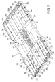
FIG. 3 is a perspective view of the battery case of the battery unit and beam members shown inFIG. 2 . -
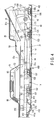
FIG. 4 is a side view of the frame structure and battery unit of the electric vehicle shown inFIG. 1 . -
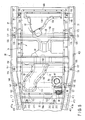
FIG. 5 is a plan view of the frame structure and battery unit of the electric vehicle shown inFIG. 1 viewed from above. -
FIG. 6 is a perspective view of the frame structure and under cover of the electric vehicle shown inFIG. 1 viewed from below. -
FIG. 7 is a perspective view of insert members to be embedded in the tray member of the battery case shown inFIG. 2 . - An embodiment of the present invention will be described below with reference to
FIGS. 1 to 7 . -
FIG. 1 shows an example of anelectric vehicle 10. Thiselectric vehicle 10 is provided with amotor 12 for traveling, andcharging equipment 13 which are arranged at the rear part of thevehicle body 11, abattery unit 14 arranged under the floor of thevehicle body 11, and the like. Aheat exchanger unit 15 for air-conditioning is arranged at the front part of thevehicle body 11. - The
front wheels 20 of thevehicle 10 are supported by thevehicle body 11 by means of front suspensions (not shown). Therear wheels 21 are supported by thevehicle body 11 by means of rear suspensions (not shown). An example of the rear suspension is a trailing arm type rear suspension. -
FIG. 2 shows aframe structure 30 constituting a lower skeletal structure of thevehicle body 11, and thebattery unit 14 to be attached to theframe structure 30. - The
frame structure 30 includes a pair of right andleft side members vehicle body 11, andcross members vehicle body 11. Thecross members side members side members cross members side members battery unit 14. - Suspension
arm support brackets side members arm support brackets side members arm support brackets axis section 42. Front end parts of the trailing arms are attached to theseaxis sections 42. - As shown in
FIG. 3 , thebattery unit 14 is provided with abattery case 50. Thebattery case 50 includes atray member 51 positioned on the lower side, and acover member 52 positioned on the upper side. A frontbattery containing section 55 is formed at the front half part of thebattery case 50. A rearbattery containing section 56 is formed at the rear half part of thebattery case 50. A centerbattery containing section 57, an electriccircuit containing section 58, and the like are formed between the frontbattery containing section 55 and rearbattery containing section 56. - A battery module 60 (only part thereof is shown by two-dot chain lines in
FIG. 3 ) is contained in each of thebattery containing sections battery module 60 is a battery module formed by connecting, in series, a plurality of cells each of which is constituted of a lithium ion battery. - A monitor for detecting a state of the
battery module 60, electric components 61 (part of them are schematically shown inFIGS. 3 and7 ) and the like for managing control and the like are contained in the electriccircuit containing section 58. Theelectric components 61 are electrically connected to thebattery modules 60. There is the possibility of theelectric components 61 being adversely affected by an electromagnetic wave, and hence theelectric components 61 are provided with an electromagnetic shield means to be described later. - As shown in
FIG. 4 , thebattery unit 14 is arranged on the undersurface side of afloor panel 70 made of steel, and having an electromagnetic shielding effect. The upper side of theelectric components 61 is magnetically shielded by thefloor panel 70. That is, thefloor panel 70 also functions as an upper electromagnetic shield portion for intercepting an electromagnetic wave from above thebattery unit 14. Further, thefloor panel 70 also functions as a shield for preventing an electromagnetic wave generated from thebattery unit 14 from being directed upward. Thefloor panel 70 extends in the back-and-forth direction and width direction of thevehicle body 11 to constitute a floor part of thevehicle body 11. - The
floor panel 70 is fixed to a predetermined position of theframe structure 30 including theside members FIG. 1 ) andrear seats 72 are arranged above thefloor panel 70. The frontbattery containing section 55 of thebattery unit 14 is arranged below thefront seats 71. The rearbattery containing section 56 of thebattery unit 14 is arranged below therear seats 72. Thefloor panel 70 includes aconcave portion 70a. Theconcave portion 70a is formed between the frontbattery containing section 55 and rearbattery containing section 56. Thisconcave portion 70a is positioned in the vicinity of the feet of the occupants seated on therear seats 72. - The
tray member 51 is a molded article formed by inserting metal insert members 200 (shown inFIG. 7 ) for reinforcement in an integrally molded synthetic resin member. Thistray member 51 is formed into a box-like shape opened at its top surface. The synthetic resin which is the material of thetray member 51 is reinforced by, for example, fibers. A cover fitting surface 80 (shown inFIG. 3 ) is formed at a peripheral edge part of the top surface of thetray member 51. Thecover fitting surface 80 is continuous over the whole circumference of thetray member 51. Awaterproof seal member 81 is provided on thecover fitting surface 80. - As shown in
FIG. 7 , theinsert members 200 includes threemetal plates tray member 51, and threemetal plates tray member 51. Thesemetal plates 200a to 200f are constituted of a metallic material having an electromagnetic shielding effect, and large bending rigidity, for example, a steel sheet. - The
metal plates battery containing section 55. A pair of right and leftreinforcement plates 201 extending rearward is provided at both ends of themetal plate 200a on the center-front side. Thesereinforcement plates 201 are provided inside the resin constitutingpartition walls 51a of thetray member 51. Thesemetal plates tray member 51. Themetal plate 200a on the center-front side functions also as a front electromagnetic shield portion positioned on the vehicle-front side with respect to theelectric components 61. - A plurality of
holes 202 are formed in thesereinforcement plates 201 in order to improve sticking of theplates 201 to the resin constituting thepartition walls 51a. Further, each of themetal plates nuts 203 protruding in the horizontal direction, ananchor bolt 204 protruding upward, andnut portions 205 each of which is provided with a threaded hole. - The
metal plates battery containing section 56 of thetray member 51. Ananchor bolt 206 protruding upward, andnut portions 207 each of which is provided with a threaded hole are provided on a top surface of each of themetal plates metal plates metal plates tray member 51. - The
metal plate 200d on the center-rear side functions also as a rear electromagnetic shield portion positioned on the vehicle-rear side with respect to theelectric components 61. It should be noted that each of a front wall and rear wall of thebattery case 50 may be provided with an electromagnetic shield member such as a metal mesh member in order to enhance the electromagnetic shielding effect at each of front and rear directions of theelectric components 61. Each of right and left walls of thebattery case 50 may also be provided with an electromagnetic shield member such as a metal mesh member in order to enhance the electromagnetic shielding effect at each of right and left areas of thebattery case 50. - The
cover member 52 is constituted of an integrally molded product of a synthetic resin reinforced by fibers. Anopening 85 for service plug and cooling air introduction opening 86 are formed at a front part of thecover member 52. A bellows-like boot 87 is attached to theopening 85 for service plug. A bellows-like boot 88 is also attached to the coolingair introduction opening 86. Abypass flow path 90 for causing part of the cooling air to flow therethrough, coolingfan containing section 91, and the like are provided on the top surface of thecover member 52. - A
flange portion 95 is formed at a peripheral edge part of thecover member 52. Theflange portion 95 is continuous over the whole circumference of thecover member 52. A rear metal plate (not shown) made of metal serving as measures against a rear collision is arranged on the rear surface of thecover member 52. The rear metal plate is fixed to thetray member 51 together with theflange portion 95 of thecover member 52, and can function as a rear electromagnetic shield portion. - The
flange portion 95 of thecover member 52 is placed on thecover fitting surface 80 of thetray member 51. Further, thetray member 51 andcover member 52 are fixed to each other through theseal member 81 in a watertight manner by means ofbolts 96 andnuts 97 shown inFIG. 3 . - A plurality of (for example, four)
beam members tray member 51. As shown inFIGS. 3 and5 , thebeam members beam bodies vehicle body 11. - The
first beam body 111 from the front is provided with joiningportions second beam body 112 from the front is provided with joiningportions third beam body 113 from the front is provided with joiningportions beam body 114 from the front is provided with joiningportions front support members battery unit 14. - The
beam members battery unit 14. Furthermore, these beam members are constituted of a metallic material (for example, a steel sheet) having an effect of intercepting an electromagnetic wave. That is, thebeam members battery unit 14. - A bolt inserting hole 143 (shown in
FIGS. 2 and3 ) is formed in each of the joiningportions first beam member 101 from the front. Thebolt inserting hole 143 penetrates the joiningportion side members unit fitting portions portions unit fitting portions FIGS. 2 and4 ) is inserted into thebolt inserting hole 143 from below the joiningportion bolt 147 is screwed into the nut member of the battery unitfitting portion portions first beam member 101 are fixed to theside members - A bolt inserting hole 153 (shown in
FIGS. 2 and3 ) is formed in each of the joiningportions second beam member 102 from the front. Thebolt inserting hole 153 penetrates the joiningportion side members unit fitting portions portions unit fitting portions FIGS. 2 and4 ) is inserted into thebolt inserting hole 153 from below the joiningportion bolt 157 is screwed into the nut member of the battery unitfitting portion portions second beam member 102 are fixed to theside members - A bolt inserting hole 163 (shown in
FIGS. 2 and3 ) is formed in each of the joiningportions third beam member 103 from the front. Thebolt inserting hole 163 penetrates the joiningportion FIGS. 4 and5 ,load transmission members side members bolts 172. Theload transmission members portions third beam member 103 from the front. The oneload transmission member 170 is welded to one suspensionarm support bracket 40. The otherload transmission member 171 is welded to the other suspensionarm support bracket 41. - That is, the
load transmission members side members arm support brackets load transmission members frame structure 30. Theload transmission members unit fitting portions - A
bolt 177 is inserted into thebolt inserting hole 163 from below the joiningportion bolt 177 is screwed into the nut member of the battery unitfitting portion portions third beam member 103 are fixed to theside members load transmission members - A bolt inserting hole 193 (shown in
FIGS. 2 and3 ) is formed in each of the joiningportions fourth beam member 104 from the front. Thebolt inserting hole 153 penetrates the joiningportion side members extension brackets portions extension brackets frame portions side members extension brackets frame structure 30. Theseextension brackets unit fitting portions - A bolt 198 (shown in
FIGS. 2 and4 ) is inserted into thebolt inserting hole 193 from below the joiningportion bolt 198 is screwed into the nut member of the battery unitfitting portion portions fourth beam member 104 are fixed to theside members extension brackets - As shown in
FIG. 4 , undersurfaces of thebeam members tray member 51. The first andsecond beam members unit fitting portions horizontal portions side members - The third and
fourth beam members unit fitting portions frame portions side members fourth beam members frame portions third beam member 103 is fixed to the batteryunit fitting portions load transmission members fourth beam member 104 is fixed to the batteryunit fitting portions extension brackets frame portions - The
front support members battery unit 14 protrude forward from thefirst beam member 101 from the front. Thefront support members beam member 101. As shown inFIG. 2 , joiningportions front support members unit fitting portions cross member 33 by means ofbolts 212. - As described above, the
beam members side members side members beam members beam members battery unit 14 can function as rigid members corresponding to the cross members. - Further, the
load transmission members arm support brackets arm support brackets beam member 103 through theload transmission members - It is possible to enhance the rigidity of the parts around the suspension
arm support brackets beam member 103 even when a cross member is not arranged near the suspensionarm support brackets electric vehicle 10 are improved. In other words, it is possible to arrange part of the large-sized battery unit 14 in a space between the pair of right and left suspensionarm support brackets sized battery unit 14 on the electric vehicle, and prolong the travel distance of the electric vehicle. - As shown in
FIGS. 1 and4 to 7 , an undercover 400 is arranged under thebattery unit 14. A top surface of theunder cover 400 is opposed to the undersurfaces of thebeam members under cover 400 is a synthetic resin reinforced with glass fibers. The undercover 400 is divided into, for example, afront half portion 400a andrear half portion 400b. By connecting thefront half portion 400a andrear half portion 400b to each other, one undercover 400 is constituted. It should be noted that an under cover integral over the whole length may also be used. - The
battery unit 14 is fixed to theframe structure 30 by means of thebolts cover 400 is fixed to at least part of theframe structure 30 andbeam members vehicle body 11 by means of bolts 401 (shown inFIG. 6 ). - An overall length of the
under cover 400 is larger than that of thebattery unit 14. That is, the undercover 400 has a length sufficient to cover from thefront end 50a to therear end 50b of thebattery case 50. A width of theunder cover 400 is larger than that of thebattery unit 14. - As shown in
FIGS. 5 and6 , the undercover 400 is arranged over the pair ofside members under cover 400 is fixed to the front cross member 33a by means of thebolts 401. A central portion of theunder cover 400 is fixed to thebeam members tray member 51. A rear portion of theunder cover 400 is fixed to brackets (not shown) provided on therear cross member 35a (shown inFIG. 6 ) by means ofbolts 401. The undercover 400 has an area sufficient to cover the whole undersurface of thebattery unit 14 when viewed from below thevehicle body 11. - The under
cover 400 has a shape opened on the rear side. As a result of this, the electromagnetic shield on the rear side of thebattery unit 14 is constituted of themetal plates tray member 51, and rear metal plate arranged on the rear surface of thecover member 52. - The
bolts under cover 400 from below. Thus, even if by any chance thebolts under cover 400. Thus, the occupant of this vehicle can recognize that a bolt has come off by the sound generated by the falling bolt striking the undercover 400, sound generated by the rolling bolt during the running, and the like. - Component dropping prevention walls 402 (shown in
FIGS. 1 and4 ) having a shape of an upward protrusion are formed at the peripheral edge portion of theunder cover 400. It is recommended that the component droppingprevention walls 402 be provided at least at positions of the entire circumference of theunder cover 400 enabling thewalls 402 to prevent thebolt cover 400. A component such as the bolt or the like that has fallen onto theunder cover 400 is retained inside theunder cover 400 by the component droppingprevention walls 402, and hence the above component is prevented from falling onto the road. - As shown in
FIG. 1 , the undercover 400 is provided with ashield member 405 having an electromagnetic shielding effect. An example of theshield member 405 is a metal mesh member formed by braiding metallic wires into a reticular form. - This
shield member 405 has a function of protecting the electric components 61 (shown inFIGS. 3 and6 ) contained inside thebattery case 50 from an electromagnetic wave. It is particularly possible to prevent an electromagnetic wave generated from themotor 12 or the like from extending to thebattery case 50 from below thevehicle body 11 by means of theshield member 405 of theunder cover 400. That is, the undercover 400 provided with theshield member 405 also functions as an under electromagnetic shield portion for intercepting an electromagnetic wave from below thebattery unit 14. - An electric component generating an electromagnetic wave is arranged between the
floor panel 70 and theunder cover 400. Above thefloor panel 70, electronic equipments such a radio, electronic clock, navigation system, and the like are arranged. In theelectronic vehicle 10 of this embodiment, it is possible to prevent an influence of the electromagnetic wave generated from the electric component from extending to the electronic equipments by the electromagnetic shield. - It should be noted that the shield member 405 (schematically shown in
FIG. 1 ) to be provided on theunder cover 400 may be provided only on part of theunder cover 400 in accordance with the intensity of the electromagnetic wave reaching thebattery case 50 from below thevehicle body 11, or the area to which the electromagnetic wave extends. Further, when the intensity of the electromagnetic wave is low to such an extent that there is practically no problem, the undercover 400 may not be provided with ashield member 405. - As shown in
FIGS. 2 ,5 , and6 , theframe structure 30 is provided withprotection members protection members cover 400. - The
protection members side members bolts 412. Theprotection members side members side members front wheels 20. Thus, theprotection members front wheels 20 when viewed from the front of thevehicle body 11. Furthermore, the undercover 400 extends rearward behind theprotection members -
Inclined surfaces protection members inclined surfaces side members protection members vehicle body 11 while the vehicle is running is guided toward the rear of theprotection members inclined surfaces - The
inclined surfaces front end 50a of thebattery case 50. The undersurfaces of theprotection members side members protection members front end 50a of thebattery case 50. Further, the undersurfaces of theprotection members under cover 400. - In this way, the pair of right and left
protection members side members beam members protection members under cover 400. - When the vehicle is passing the large convex part such as a step or the like, it can be presumed, depending on the situation, for example, that the convex part of the road surface hits the under
cover 400 at around thefront end 400c thereof. In this case, the load of the collision is received by the cross member 33a arranged near thefront end 400c of theunder cover 400, and the convex part of the road surface is guided toward the rear side of thevehicle body 11 along theunder cover 400. This makes it possible to prevent the convex part of the road surface from hitting thebattery unit 14. - Depending on the situation during the travel of the vehicle, it can be presumed that the convex part of the road surface collides against at least one of the
protection members inclined surfaces protection members vehicle body 11. In this case, theinclined surfaces protection members inclined surfaces under cover 400. As a result of this, it is possible to prevent the convex part of the road surface from directly hitting thebattery unit 14. - The
beam members under cover 400 from the front side of thevehicle body 11 toward the rear side thereof. Thesebeam members protection members under cover 400 to exert high strength against external force applied thereto from below. Thus, it is possible to guide the convex part of the road surface that has been brought into contact with theunder cover 400 toward the rear side of thevehicle body 11 along theunder cover 400. In this way, thebattery unit 14 can be prevented from being damaged. The undercover 400 has an effect of straightening the air current generated on the undersurface side of thevehicle body 11 while the vehicle is running, and can reduce the air resistance while the vehicle is running. - In the
electric vehicle 10 of this embodiment, thebattery unit 14 is arranged below thefloor panel 70 made of metal. Thefloor panel 70 functions as an upper electromagnetic shield portion. Further, thebattery unit 14 is arranged between the right and leftside members side members circuit containing section 58. Theseside members battery unit 14. Further,the.cross members - Furthermore, the
beam members battery case 50. Further, themetal plates battery case 50 function as the front electromagnetic shield portion and rear electromagnetic shield portion, respectively. - Moreover, the under
cover 400 provided with the electromagnetic shield means such as theshield member 405 is present under thebattery case 50. When thebeam members 101 to 104 made of metal are present above theunder cover 400, thebeam members 101 to 104 exhibit an electromagnetic shielding effect. This makes it possible to reduce or omit the electromagnetic shield means-to be provided on theunder cover 400. That is, portions of theunder cover 400 overlapping thebeam members 101 to 104 when viewed from above thevehicle body 11 may not be provided with theshield member 405. - By providing the electromagnetic shield means described above, it is possible to prevent the
electric components 61 inside thebattery case 50 from being adversely affected by an electromagnetic wave even when the paint for electromagnetic shield is not applied to thebattery case 50. Further, even if an electromagnetic wave is generated inside thebattery case 50, it is possible to prevent the electromagnetic wave from being radiated to the outside of thebattery case 50. According to the electromagnetic shield portions of this embodiment, it is possible not to arrange a conductive member for electromagnetic shielding on the inner surface of thebattery case 50 in a naked state. As a result of this, the conductive members for electromagnetic shielding do not give rise to a short circuit, which provides safety. - In the above embodiment, an electric vehicle in which a motor for running is mounted on the rear part of the vehicle body has been described. However, the present invention can also be applied to an electric vehicle in which a motor for running is mounted on the front part of the vehicle body. Further, in carrying out the present invention, it goes without saying that the structures and arrangements of the constituent elements of the present invention such as the side members, floor panel, motor, battery unit, front electromagnetic shield portion, rear electromagnetic shield portion, under electromagnetic shield portion, and the like can be appropriately modified and implemented.
Claims (4)
- An electric vehicle comprising:a frame structure (30) including a pair of right and left side members (31, 32) made of metal, arranged at a lower part of a vehicle body (11);a floor panel (70) made of metal provided on the frame structure (30);a battery unit (14) including a battery case (50) arranged between the pair of side members (31, 32) on the undersurface side of the floor panel (70), the battery case (50) containing therein battery modules (60) and electric components (61) electrically connected to the battery modules (60), and the upper side of the electric components (61) being electromagnetically shielded by the floor panel (70);a front electromagnetic shield portion arranged on the vehicle-front side with respect to the electric components (61);a rear electromagnetic shield portion arranged on the vehicle-rear side with respect to the electric components (61); andan under electromagnetic shield portion arranged on the undersurface side of the battery case (50).
- The electric vehicle according to claim 1, wherein each of the front electromagnetic shield portion and the rear electromagnetic shield portion is constituted of an insert member (200) made of metal embedded in the resin constituting the battery case (50).
- The electric vehicle according to claim 1 or 2, wherein an under cover (400) for covering the battery case (50) from below is arranged below the battery case (50), and the under electromagnetic shield portion is constituted of a shield member (405) provided on the under cover (400).
- The electric vehicle according to claim 3, wherein beam members (101, 102, 103, 104) made of metal, extending in the width direction of the vehicle body (11) are provided under the battery case (50), both end portions of these beam members are supported by the pair of side members (31, 32), the under electromagnetic shield portion is constituted of these beam members, and portions overlapping the beam members (101, 102, 103, 104) when viewed from above the vehicle body (11) are not provided with the shield member (405) of the under cover (400).
Applications Claiming Priority (2)
| Application Number | Priority Date | Filing Date | Title |
|---|---|---|---|
| JP2007254261A JP5029263B2 (en) | 2007-09-28 | 2007-09-28 | Electric car |
| PCT/JP2008/053995 WO2009041079A1 (en) | 2007-09-28 | 2008-03-05 | Electric automobile |
Publications (3)
| Publication Number | Publication Date |
|---|---|
| EP2072309A1 true EP2072309A1 (en) | 2009-06-24 |
| EP2072309A4 EP2072309A4 (en) | 2013-05-29 |
| EP2072309B1 EP2072309B1 (en) | 2015-07-29 |
Family
ID=40510983
Family Applications (1)
| Application Number | Title | Priority Date | Filing Date |
|---|---|---|---|
| EP08721415.1A Active EP2072309B1 (en) | 2007-09-28 | 2008-03-05 | Electric automobile |
Country Status (5)
| Country | Link |
|---|---|
| US (1) | US8079435B2 (en) |
| EP (1) | EP2072309B1 (en) |
| JP (1) | JP5029263B2 (en) |
| CN (1) | CN101568443B (en) |
| WO (1) | WO2009041079A1 (en) |
Cited By (6)
| Publication number | Priority date | Publication date | Assignee | Title |
|---|---|---|---|---|
| WO2013020700A1 (en) * | 2011-08-09 | 2013-02-14 | Rehau Ag + Co | Battery housing part for shielding electromagnetic radiation for a battery housing of a traction battery of an electric vehicle and method for producing the battery housing part |
| EP2624332A1 (en) * | 2012-02-06 | 2013-08-07 | Mitsubishi Jidosha Kogyo Kabushiki Kaisha | Pouring structure for battery pack |
| EP2703203A1 (en) * | 2012-08-31 | 2014-03-05 | Yazaki Corporation | Attaching structure capable of preventing a service-plug from exposure to water |
| KR101393848B1 (en) * | 2012-10-09 | 2014-05-12 | 기아자동차주식회사 | High voltage battery pack of electric vehicle |
| DE102014213676A1 (en) | 2014-07-15 | 2016-01-21 | Robert Bosch Gmbh | Sheath for a battery cell and for a battery system, method for producing the sheath and battery cell and battery system |
| WO2019007730A1 (en) * | 2017-07-04 | 2019-01-10 | Audi Ag | MOTOR VEHICLE AND METHOD FOR ARRANGING AT LEAST ONE TRACTION ENERGY STORAGE IN A MOTOR VEHICLE |
Families Citing this family (109)
| Publication number | Priority date | Publication date | Assignee | Title |
|---|---|---|---|---|
| PE20110470A1 (en) | 2008-06-27 | 2011-07-15 | Proterra Inc | BATTERY SYSTEMS AND METHODS FOR VEHICLES |
| JP4911262B2 (en) * | 2009-03-12 | 2012-04-04 | トヨタ自動車株式会社 | Electric vehicle |
| JP5640382B2 (en) * | 2009-05-26 | 2014-12-17 | 日産自動車株式会社 | Vehicle battery assembly cooling structure and battery assembly with water jacket |
| JP5531626B2 (en) * | 2009-05-26 | 2014-06-25 | 日産自動車株式会社 | Vehicle battery assembly cooling structure and battery assembly with water jacket |
| JP2010284984A (en) * | 2009-06-09 | 2010-12-24 | Fuji Heavy Ind Ltd | Vehicle battery mounting structure |
| DE102009031779A1 (en) * | 2009-07-06 | 2011-01-13 | GM Global Technology Operations, Inc., Detroit | Floor structure for a motor vehicle |
| FR2951129A1 (en) | 2009-10-12 | 2011-04-15 | Plastic Omnium Cie | VEHICLE STRUCTURE COMPRISING A BATTERY |
| US20130126254A1 (en) * | 2009-11-03 | 2013-05-23 | V-Ens Co., Ltd. | Motor vehicle |
| US20120223113A1 (en) * | 2009-11-18 | 2012-09-06 | Benteler Aluminium Systems France SNC | Battery Tray for Vehicle and Method for Producing the Battery Tray |
| JP5408441B2 (en) * | 2010-01-18 | 2014-02-05 | 三菱自動車工業株式会社 | Battery case for vehicle |
| US7913788B1 (en) * | 2010-02-09 | 2011-03-29 | Gm Global Technology Operations, Llc | Integrated energy storage and rear suspension assembly |
| CN102205787B (en) * | 2010-03-30 | 2015-04-29 | 上海奕代汽车技术有限公司 | Battery installation structure of electric car |
| CN102387928A (en) * | 2010-04-05 | 2012-03-21 | 科达汽车公司 | Electric vehicle with structurally integrated components |
| FR2962965B1 (en) * | 2010-07-23 | 2014-02-14 | Renault Sa | AUTOMOTIVE VEHICLE CHASSIS AND METHOD FOR ASSEMBLING THE BODY |
| JP2012026522A (en) * | 2010-07-23 | 2012-02-09 | Mitsubishi Motors Corp | Bolt and mounting structure of battery using the same |
| DE102010034925A1 (en) * | 2010-08-20 | 2012-02-23 | Gm Global Technology Operations Llc (N.D.Ges.D. Staates Delaware) | Energy storage arrangement in the floor area of a vehicle |
| KR20120044853A (en) * | 2010-10-28 | 2012-05-08 | 현대자동차주식회사 | Battery Pack Case Assembly for Electric Vehicle Using Plastic Composite |
| JP5360041B2 (en) * | 2010-12-15 | 2013-12-04 | 三菱自動車工業株式会社 | Battery case |
| US8286743B2 (en) * | 2010-12-22 | 2012-10-16 | Tesla Motors, Inc. | Vehicle battery pack ballistic shield |
| US8336658B2 (en) * | 2010-12-22 | 2012-12-25 | Tesla Motors, Inc. | Augmented vehicle seat mount |
| US20120161472A1 (en) | 2010-12-22 | 2012-06-28 | Tesla Motors, Inc. | System for Absorbing and Distributing Side Impact Energy Utilizing an Integrated Battery Pack |
| US8696051B2 (en) | 2010-12-22 | 2014-04-15 | Tesla Motors, Inc. | System for absorbing and distributing side impact energy utilizing a side sill assembly with a collapsible sill insert |
| US8875828B2 (en) | 2010-12-22 | 2014-11-04 | Tesla Motors, Inc. | Vehicle battery pack thermal barrier |
| JP5656071B2 (en) * | 2010-12-28 | 2015-01-21 | スズキ株式会社 | Electric vehicle |
| JP5861484B2 (en) * | 2011-03-11 | 2016-02-16 | 日産自動車株式会社 | Automotive battery |
| JP5946031B2 (en) * | 2011-03-17 | 2016-07-05 | 合同会社亀屋 | Vehicle / hull structure |
| EP2682999B1 (en) * | 2011-05-19 | 2017-01-11 | Lg Chem, Ltd. | Battery pack having excellent structural reliability |
| KR101273080B1 (en) * | 2011-07-21 | 2013-06-10 | 기아자동차주식회사 | Mounting structure for battery in electric vehicle |
| JP5850689B2 (en) * | 2011-09-29 | 2016-02-03 | 株式会社イノアックコーポレーション | Vehicle electromagnetic shielding cover |
| KR101294176B1 (en) | 2011-10-25 | 2013-08-08 | 기아자동차주식회사 | Battery system for preventing electromechanical wave of battery management system |
| DE102011118181A1 (en) * | 2011-11-10 | 2013-05-16 | GM Global Technology Operations LLC (n. d. Gesetzen des Staates Delaware) | Cross member of a motor vehicle body |
| JP5906689B2 (en) * | 2011-11-22 | 2016-04-20 | トヨタ自動車株式会社 | Vehicle battery mounting structure |
| JP5692019B2 (en) * | 2011-11-22 | 2015-04-01 | トヨタ自動車株式会社 | Service hole cover mounting structure and vehicle battery mounting structure including the same |
| JP5887883B2 (en) * | 2011-11-29 | 2016-03-16 | トヨタ自動車株式会社 | Vehicle battery mounting structure |
| US20130168168A1 (en) * | 2011-12-28 | 2013-07-04 | Kawasaki Jukogyo Kabushiki Kaisha | Hybrid Vehicle |
| JP5929211B2 (en) * | 2012-01-13 | 2016-06-01 | 三菱自動車工業株式会社 | undercover |
| US8232699B2 (en) * | 2012-01-13 | 2012-07-31 | Letang Kyli Irene | Magnetically levitating vehicle |
| JP5970825B2 (en) * | 2012-01-17 | 2016-08-17 | 三菱自動車工業株式会社 | undercover |
| JP5880086B2 (en) * | 2012-01-31 | 2016-03-08 | 三菱自動車工業株式会社 | Battery container |
| JP5925290B2 (en) * | 2012-02-29 | 2016-05-25 | 住友重機械工業株式会社 | Excavator |
| JP6020958B2 (en) * | 2012-07-13 | 2016-11-02 | 三菱自動車工業株式会社 | Battery pack tray |
| JP5949443B2 (en) * | 2012-10-24 | 2016-07-06 | 三菱自動車工業株式会社 | Waterproof structure of the earth part of electromagnetic shielding material |
| JP5870457B2 (en) * | 2012-11-08 | 2016-03-01 | 本田技研工業株式会社 | Electric vehicle |
| DE102012023363B4 (en) * | 2012-11-29 | 2014-06-26 | Audi Ag | Subframe for a motor vehicle |
| US11352062B2 (en) | 2012-12-21 | 2022-06-07 | Dr. Ing. H. C. F. Porsche Ag | Subframe for holding an electric energy accumulator in a motor vehicle |
| DE102012112966B4 (en) * | 2012-12-21 | 2025-08-14 | Dr. Ing. H.C. F. Porsche Aktiengesellschaft | Subframe for accommodating an electrical energy storage device in a motor vehicle |
| CN103066225B (en) * | 2013-01-24 | 2015-08-19 | 东风汽车公司 | Power battery of pure electric automobile bag assembly structure |
| JP6021676B2 (en) * | 2013-02-14 | 2016-11-09 | 富士重工業株式会社 | Body structure of electric powered vehicle |
| CN103465763A (en) * | 2013-08-19 | 2013-12-25 | 北京汽车新能源汽车有限公司 | A0-grade pure electric car power battery arrangement scheme |
| US9016765B1 (en) * | 2013-12-19 | 2015-04-28 | Atieva, Inc. | Readily replaceable EV battery pack ballistic shield |
| US9139074B2 (en) | 2014-01-16 | 2015-09-22 | Ford Global Technologies, Llc | Methods and devices for positioning a traction battery on a hybrid or electric vehicle |
| DE102014102202A1 (en) * | 2014-02-20 | 2015-08-20 | Dr. Ing. H.C. F. Porsche Aktiengesellschaft | Battery carrier for a battery case of a motor vehicle battery |
| DE102014107388A1 (en) * | 2014-05-26 | 2015-11-26 | Dr. Ing. H.C. F. Porsche Aktiengesellschaft | Underbody unit for a motor vehicle |
| DE102014212540A1 (en) * | 2014-06-30 | 2015-12-31 | Robert Bosch Gmbh | Vehicle with improved battery shield |
| US9187136B1 (en) * | 2014-08-01 | 2015-11-17 | Honda Motor Co., Ltd. | Structural pan for automotive body/frame |
| MX384871B (en) * | 2015-01-21 | 2025-03-14 | Waev Inc | ELECTRIC VEHICLE. |
| JP6488826B2 (en) * | 2015-03-31 | 2019-03-27 | 株式会社デンソー | Disturbance prevention cover |
| US9643660B2 (en) | 2015-08-27 | 2017-05-09 | Atieva, Inc. | Bumper assembly for an undercarriage mounted battery pack |
| CN105128644B (en) * | 2015-09-29 | 2017-08-22 | 北京理工大学 | A kind of arrangement of the power battery pack of distributed four-wheel In-wheel motor driving electric automobile |
| JP6101768B1 (en) * | 2015-09-30 | 2017-03-22 | 富士重工業株式会社 | Collision load relaxation structure |
| JP6041037B2 (en) * | 2015-12-16 | 2016-12-07 | 三菱自動車工業株式会社 | undercover |
| WO2018033880A2 (en) | 2016-08-17 | 2018-02-22 | Shape Corp. | Battery support and protection structure for a vehicle |
| JP6515073B2 (en) * | 2016-08-24 | 2019-05-15 | 本田技研工業株式会社 | Power supply unit case structure |
| US10597083B2 (en) * | 2016-09-07 | 2020-03-24 | Thunder Power Electric Vehicle Limited | Placement of battery elements in tunnel |
| US10549620B2 (en) * | 2016-09-07 | 2020-02-04 | Thunder Power Electric Vehicle Limited | Profiles in the floor section |
| US10431791B2 (en) * | 2016-11-01 | 2019-10-01 | Ford Global Technologies, Llc | Traction battery pack shield and shielding method |
| US10381621B2 (en) * | 2016-11-01 | 2019-08-13 | Ford Global Technologies, Llc | Traction battery energy absorbing method and assembly |
| EP3566253B1 (en) | 2017-01-04 | 2022-12-28 | Shape Corp. | Battery support structure for a vehicle |
| US10112470B2 (en) * | 2017-01-11 | 2018-10-30 | GM Global Technology Operations LLC | Structural enhancements of an electric vehicle |
| HRP20221219T1 (en) * | 2017-02-17 | 2022-12-23 | Mubea Carbo Tech Gmbh | Battery structure and protector |
| JP6686948B2 (en) * | 2017-03-23 | 2020-04-22 | トヨタ自動車株式会社 | Vehicle substructure |
| WO2018213383A1 (en) | 2017-05-16 | 2018-11-22 | Shape Corp. | Vehicle battery tray with integrated battery retention and support features |
| US10886513B2 (en) | 2017-05-16 | 2021-01-05 | Shape Corp. | Vehicle battery tray having tub-based integration |
| US10483510B2 (en) | 2017-05-16 | 2019-11-19 | Shape Corp. | Polarized battery tray for a vehicle |
| US10202028B1 (en) | 2017-08-09 | 2019-02-12 | Ford Global Technologies, Llc | Vehicle Traction Battery Sub-Frame Assembly |
| WO2019055658A2 (en) | 2017-09-13 | 2019-03-21 | Shape Corp. | Vehicle battery tray with tubular peripheral wall |
| US12347879B2 (en) | 2017-09-13 | 2025-07-01 | Shape Corp. | Vehicle battery tray with tubular peripheral wall |
| DE112018005556T5 (en) | 2017-10-04 | 2020-06-25 | Shape Corp. | BATTERY RACK FLOOR ASSEMBLY FOR ELECTRIC VEHICLES |
| JP6859933B2 (en) * | 2017-11-17 | 2021-04-14 | トヨタ自動車株式会社 | Vehicle battery case and its manufacturing method |
| EP3511184A1 (en) * | 2018-01-15 | 2019-07-17 | MAGNA STEYR Fahrzeugtechnik AG & Co KG | Motor vehicle with a support structure |
| JP6992585B2 (en) * | 2018-02-22 | 2022-01-13 | トヨタ自動車株式会社 | Vehicle undercarriage |
| JP7095307B2 (en) * | 2018-02-23 | 2022-07-05 | トヨタ自動車株式会社 | Vehicle undercarriage |
| WO2019169080A1 (en) | 2018-03-01 | 2019-09-06 | Shape Corp. | Cooling system integrated with vehicle battery tray |
| JP6996352B2 (en) * | 2018-03-06 | 2022-01-17 | トヨタ自動車株式会社 | Vehicle lower body structure |
| JP6988590B2 (en) * | 2018-03-09 | 2022-01-05 | トヨタ自動車株式会社 | Vehicle rear structure |
| JP7006390B2 (en) * | 2018-03-09 | 2022-01-24 | トヨタ自動車株式会社 | Vehicle lower body structure |
| US11688910B2 (en) | 2018-03-15 | 2023-06-27 | Shape Corp. | Vehicle battery tray having tub-based component |
| US10259507B1 (en) * | 2018-03-22 | 2019-04-16 | Honda Motor Co., Ltd. | Skid plate and underbody assembly for use with an off-road vehicle |
| FR3081261B1 (en) | 2018-05-18 | 2020-04-24 | Faurecia Systemes D'echappement | BATTERY AND VEHICLE EQUIPPED WITH SUCH A BATTERY |
| US10780923B2 (en) * | 2018-07-13 | 2020-09-22 | Ford Global Technologies, Llc | Vehicle platform |
| US10618425B2 (en) * | 2018-09-10 | 2020-04-14 | Ford Global Technologies, Llc | High voltage battery pack mounting systems for electrified vehicles |
| CN116252868B (en) * | 2018-09-20 | 2024-08-09 | 本田技研工业株式会社 | Vehicle body lower structure |
| CN113613926B (en) * | 2018-11-20 | 2023-08-11 | 泰普爱复合材料股份有限公司 | Composite battery case |
| WO2020146730A1 (en) * | 2019-01-10 | 2020-07-16 | Quadrobot Inc. | Integrated vehicle frame |
| KR102730525B1 (en) * | 2019-02-12 | 2024-11-13 | 현대자동차주식회사 | Protective apparatus of high voltage battery for vehicle |
| US10822039B2 (en) * | 2019-02-18 | 2020-11-03 | GM Global Technology Operations LLC | Body rocker, battery cross-bar, and body cross-bar configuration for load distribution between vehicle body and under-vehicle battery |
| DE102019130854A1 (en) | 2019-03-18 | 2020-09-24 | Dr. Ing. H.C. F. Porsche Aktiengesellschaft | Holding device for power and signal conductors of a traction battery of a motor vehicle |
| DE102019114006B4 (en) * | 2019-05-24 | 2023-12-21 | Benteler Automobiltechnik Gmbh | Coupling element for connecting vehicle components of an underbody arrangement and underbody arrangement of a battery-operated motor vehicle |
| CN113939417A (en) * | 2019-06-05 | 2022-01-14 | Avl动力工程公司 | Vehicle frame assembly and power tray |
| CN121406886A (en) | 2020-01-03 | 2026-01-27 | 特斯拉公司 | Selective extraction of lithium from clay minerals |
| WO2021220027A1 (en) * | 2020-04-28 | 2021-11-04 | 日産自動車株式会社 | Electric vehicle floor structure |
| US20220223947A1 (en) * | 2020-07-03 | 2022-07-14 | Continental Structure Plastics, Inc. | Puncture resistant shield of a battery containment system |
| JP7476080B2 (en) * | 2020-11-11 | 2024-04-30 | 本田技研工業株式会社 | Body structure |
| CN214689046U (en) * | 2020-12-23 | 2021-11-12 | 比亚迪股份有限公司 | Battery package protection system and vehicle |
| JP7549805B2 (en) * | 2021-03-22 | 2024-09-12 | スズキ株式会社 | Vehicle battery pack peripheral structure |
| JP7813629B2 (en) * | 2022-03-25 | 2026-02-13 | 日産自動車株式会社 | Vehicle drive battery mounting structure |
| DE102022107486B3 (en) * | 2022-03-30 | 2023-05-04 | Dr. Ing. H.C. F. Porsche Aktiengesellschaft | Vehicle part structure for an at least partially electrically powered motor vehicle |
| CN117638352A (en) * | 2022-08-11 | 2024-03-01 | 福特全球技术公司 | Vehicle battery protection frame and corresponding vehicle |
| DE102024105009B3 (en) | 2024-02-22 | 2025-02-20 | Dr. Ing. H.C. F. Porsche Aktiengesellschaft | motor vehicle with an underrun protection |
Family Cites Families (38)
| Publication number | Priority date | Publication date | Assignee | Title |
|---|---|---|---|---|
| US4365681A (en) * | 1980-12-22 | 1982-12-28 | General Motors Corporation | Battery support structure |
| US5390754A (en) * | 1992-01-16 | 1995-02-21 | Honda Giken Kogyo Kabushiki Kaisha | Battery box for an electric vehicle |
| JP3229637B2 (en) * | 1992-01-23 | 2001-11-19 | 本田技研工業株式会社 | Battery cooling structure for electric vehicles |
| US5501289A (en) * | 1993-01-22 | 1996-03-26 | Nissan Motor Co., Ltd. | Floor structure of electric vehicle |
| US5704644A (en) * | 1993-02-27 | 1998-01-06 | Esoro Ag | Lightweight road vehicle with strengthening structure |
| JP3350189B2 (en) * | 1993-04-30 | 2002-11-25 | 本田技研工業株式会社 | Battery box device for electric vehicles |
| JP3420349B2 (en) * | 1994-09-07 | 2003-06-23 | セイコーエプソン株式会社 | Electric power unit and power transmission unit for electric vehicle |
| US6085854A (en) * | 1994-12-13 | 2000-07-11 | Nissan Motor Co., Ltd. | Battery frame structure for electric motorcar |
| JPH08186390A (en) * | 1994-12-28 | 1996-07-16 | Uchihama Kasei Kk | Battery case for electric vehicle |
| US5594199A (en) * | 1995-03-23 | 1997-01-14 | Ford Motor Company | EMI baffle for electronic control |
| DE19512255A1 (en) * | 1995-03-31 | 1996-10-02 | Siemens Ag | Arrangement for receiving an insert body in a receiving body |
| US5948298A (en) * | 1996-04-26 | 1999-09-07 | Ford Global Technologies, Inc. | Battery heating system |
| JP3480286B2 (en) * | 1997-12-08 | 2003-12-15 | 日産自動車株式会社 | Battery frame structure for electric vehicles |
| US6598691B2 (en) * | 1997-12-18 | 2003-07-29 | Honda Giken Kogyo Kabushiki Kaisha | Electric vehicle |
| US6189635B1 (en) * | 1998-03-09 | 2001-02-20 | Navistar International Transportation Corp. | Polyurethane/polyurea elastomer coated steel battery box for hybrid electric vehicle applications |
| US6109380A (en) * | 1998-04-13 | 2000-08-29 | Ford Global Technologies, Inc. | Electric vehicle vertical wall construction battery tray |
| JP2000040535A (en) * | 1998-07-21 | 2000-02-08 | Honda Motor Co Ltd | Electric vehicle cooling structure |
| JP3498636B2 (en) * | 1999-06-09 | 2004-02-16 | 日産自動車株式会社 | Battery mounting structure for electric vehicles |
| US6483719B1 (en) * | 2000-03-21 | 2002-11-19 | Spraylat Corporation | Conforming shielded form for electronic component assemblies |
| JP2001294048A (en) * | 2000-04-13 | 2001-10-23 | Toyota Motor Corp | Power supply for vehicles |
| US20040161664A1 (en) * | 2001-08-14 | 2004-08-19 | Mitsubishi Denki Kabushiki Kaisha (A Corporation Of Japan) | Plate shaped battery pack and portable radio terminal |
| US6773846B2 (en) * | 2002-08-19 | 2004-08-10 | Allis Electric Co., Ltd. | Mobile rack type battery box for UPS system |
| JP4109953B2 (en) * | 2002-10-03 | 2008-07-02 | トヨタ自動車株式会社 | Vehicle with fuel cell |
| DE10249437A1 (en) * | 2002-10-24 | 2004-06-24 | Daimlerchrysler Ag | Arrangement of a power generation system in an electric vehicle and method for assembling or installing the power generation system in the electric vehicle |
| JP4127046B2 (en) * | 2002-12-20 | 2008-07-30 | 日産自動車株式会社 | Fuel cell vehicle |
| US7051825B2 (en) * | 2003-05-21 | 2006-05-30 | Honda Motor Co., Ltd. | Structure for installing high-voltage equipment component to vehicle |
| JP3934110B2 (en) * | 2004-01-22 | 2007-06-20 | 本田技研工業株式会社 | Fuel cell vehicle mounting structure |
| JP2006035915A (en) * | 2004-07-22 | 2006-02-09 | Sanyo Electric Co Ltd | Power supply for vehicle |
| JP4576931B2 (en) * | 2004-08-27 | 2010-11-10 | トヨタ自動車株式会社 | Electrical equipment mounting structure |
| JP4670382B2 (en) * | 2005-02-16 | 2011-04-13 | トヨタ自動車株式会社 | Battery pack and car |
| US7950482B2 (en) * | 2005-02-28 | 2011-05-31 | Toyota Jidosha Kabushiki Kaisha | Fuel cell system and vehicle using fuel cell |
| JP4385020B2 (en) * | 2005-06-02 | 2009-12-16 | 本田技研工業株式会社 | Vehicle power supply |
| JP4274165B2 (en) * | 2005-10-06 | 2009-06-03 | トヨタ自動車株式会社 | Cooling device for on-vehicle equipment |
| JP5141026B2 (en) * | 2006-02-27 | 2013-02-13 | トヨタ自動車株式会社 | In-vehicle structure of power storage pack |
| JP4940749B2 (en) * | 2006-04-28 | 2012-05-30 | トヨタ自動車株式会社 | Power supply device mounting structure |
| CN102050009B (en) * | 2006-09-07 | 2013-03-13 | 本田技研工业株式会社 | Electrical device cooling structure in vehicle |
| GB2446229B (en) * | 2007-02-05 | 2010-12-29 | Akhter Group Plc | Battery system for electrical vehicle |
| US7614469B2 (en) * | 2007-05-07 | 2009-11-10 | General Electric Company | Battery case and method for securing same |
-
2007
- 2007-09-28 JP JP2007254261A patent/JP5029263B2/en active Active
-
2008
- 2008-03-05 CN CN200880000803XA patent/CN101568443B/en active Active
- 2008-03-05 WO PCT/JP2008/053995 patent/WO2009041079A1/en not_active Ceased
- 2008-03-05 EP EP08721415.1A patent/EP2072309B1/en active Active
-
2009
- 2009-03-24 US US12/410,148 patent/US8079435B2/en active Active
Cited By (9)
| Publication number | Priority date | Publication date | Assignee | Title |
|---|---|---|---|---|
| WO2013020700A1 (en) * | 2011-08-09 | 2013-02-14 | Rehau Ag + Co | Battery housing part for shielding electromagnetic radiation for a battery housing of a traction battery of an electric vehicle and method for producing the battery housing part |
| EP2624332A1 (en) * | 2012-02-06 | 2013-08-07 | Mitsubishi Jidosha Kogyo Kabushiki Kaisha | Pouring structure for battery pack |
| EP2703203A1 (en) * | 2012-08-31 | 2014-03-05 | Yazaki Corporation | Attaching structure capable of preventing a service-plug from exposure to water |
| US9499057B2 (en) | 2012-08-31 | 2016-11-22 | Yazaki Corporation | Attaching structure capable of preventing a service-plug from exposure to water |
| KR101393848B1 (en) * | 2012-10-09 | 2014-05-12 | 기아자동차주식회사 | High voltage battery pack of electric vehicle |
| DE102014213676A1 (en) | 2014-07-15 | 2016-01-21 | Robert Bosch Gmbh | Sheath for a battery cell and for a battery system, method for producing the sheath and battery cell and battery system |
| US9647247B2 (en) | 2014-07-15 | 2017-05-09 | Robert Bosch Gmbh | Encasement for a battery cell and for a battery system, process for producing said encasement, battery cell and battery system |
| WO2019007730A1 (en) * | 2017-07-04 | 2019-01-10 | Audi Ag | MOTOR VEHICLE AND METHOD FOR ARRANGING AT LEAST ONE TRACTION ENERGY STORAGE IN A MOTOR VEHICLE |
| US11225151B2 (en) | 2017-07-04 | 2022-01-18 | Audi Ag | Motor vehicle and method for arranging at least one traction energy storage device in a motor vehicle |
Also Published As
| Publication number | Publication date |
|---|---|
| EP2072309A4 (en) | 2013-05-29 |
| EP2072309B1 (en) | 2015-07-29 |
| WO2009041079A1 (en) | 2009-04-02 |
| CN101568443A (en) | 2009-10-28 |
| JP2009083599A (en) | 2009-04-23 |
| JP5029263B2 (en) | 2012-09-19 |
| US20090242299A1 (en) | 2009-10-01 |
| US8079435B2 (en) | 2011-12-20 |
| CN101568443B (en) | 2012-06-20 |
Similar Documents
| Publication | Publication Date | Title |
|---|---|---|
| EP2072309B1 (en) | Electric automobile | |
| TWI603878B (en) | Frame structure for use in truck-type electric vehicle | |
| EP2207224B1 (en) | Battery case for electric automobile | |
| JP4888311B2 (en) | Electric car | |
| JP5595442B2 (en) | Car power supply mounting structure | |
| CN110901362B (en) | Vehicle Substructure | |
| US11230177B2 (en) | Battery system of vehicle | |
| US12126038B2 (en) | Electrified vehicle | |
| JP7796570B2 (en) | Vehicle body device protection structure | |
| CN110182262B (en) | Vehicle lower structure | |
| JPH06199183A (en) | Console box for electric vehicle | |
| US20230264558A1 (en) | Vehicle-body front structure including reinforcement members | |
| JP7077863B2 (en) | Shift bracket | |
| JP7487705B2 (en) | Floor Structure | |
| CN118339043B (en) | Mounting structure for electric equipment | |
| US20250183438A1 (en) | Battery enclosure for electric vehicles | |
| US20250242679A1 (en) | Electrified vehicle | |
| JP2020179693A (en) | Vehicle equipment mounting structure | |
| WO2024257765A1 (en) | Side structure of vehicle | |
| JP2026082060A (en) | Vehicle structure | |
| JP2024119736A (en) | Automotive Battery Case | |
| CN119365357A (en) | Support device for driving battery | |
| JP2021126915A (en) | Vehicle structure |
Legal Events
| Date | Code | Title | Description |
|---|---|---|---|
| PUAI | Public reference made under article 153(3) epc to a published international application that has entered the european phase |
Free format text: ORIGINAL CODE: 0009012 |
|
| 17P | Request for examination filed |
Effective date: 20090325 |
|
| AK | Designated contracting states |
Kind code of ref document: A1 Designated state(s): DE FR GB |
|
| DAX | Request for extension of the european patent (deleted) | ||
| A4 | Supplementary search report drawn up and despatched |
Effective date: 20130426 |
|
| RIC1 | Information provided on ipc code assigned before grant |
Ipc: B60L 11/18 20060101ALI20130422BHEP Ipc: H05K 9/00 20060101ALI20130422BHEP Ipc: H01M 2/10 20060101ALI20130422BHEP Ipc: B60K 1/04 20060101AFI20130422BHEP |
|
| 17Q | First examination report despatched |
Effective date: 20140417 |
|
| GRAP | Despatch of communication of intention to grant a patent |
Free format text: ORIGINAL CODE: EPIDOSNIGR1 |
|
| INTG | Intention to grant announced |
Effective date: 20150206 |
|
| GRAS | Grant fee paid |
Free format text: ORIGINAL CODE: EPIDOSNIGR3 |
|
| GRAA | (expected) grant |
Free format text: ORIGINAL CODE: 0009210 |
|
| AK | Designated contracting states |
Kind code of ref document: B1 Designated state(s): DE FR GB |
|
| REG | Reference to a national code |
Ref country code: GB Ref legal event code: FG4D |
|
| REG | Reference to a national code |
Ref country code: DE Ref legal event code: R096 Ref document number: 602008039239 Country of ref document: DE |
|
| REG | Reference to a national code |
Ref country code: FR Ref legal event code: PLFP Year of fee payment: 9 |
|
| REG | Reference to a national code |
Ref country code: DE Ref legal event code: R097 Ref document number: 602008039239 Country of ref document: DE |
|
| PLBE | No opposition filed within time limit |
Free format text: ORIGINAL CODE: 0009261 |
|
| STAA | Information on the status of an ep patent application or granted ep patent |
Free format text: STATUS: NO OPPOSITION FILED WITHIN TIME LIMIT |
|
| 26N | No opposition filed |
Effective date: 20160502 |
|
| REG | Reference to a national code |
Ref country code: FR Ref legal event code: PLFP Year of fee payment: 10 |
|
| REG | Reference to a national code |
Ref country code: FR Ref legal event code: PLFP Year of fee payment: 11 |
|
| PGFP | Annual fee paid to national office [announced via postgrant information from national office to epo] |
Ref country code: DE Payment date: 20250128 Year of fee payment: 18 |
|
| PGFP | Annual fee paid to national office [announced via postgrant information from national office to epo] |
Ref country code: FR Payment date: 20250210 Year of fee payment: 18 |
|
| PGFP | Annual fee paid to national office [announced via postgrant information from national office to epo] |
Ref country code: GB Payment date: 20250130 Year of fee payment: 18 |