EP2072307A2 - Convertible top having movable outboard panels - Google Patents
Convertible top having movable outboard panels Download PDFInfo
- Publication number
- EP2072307A2 EP2072307A2 EP08021783A EP08021783A EP2072307A2 EP 2072307 A2 EP2072307 A2 EP 2072307A2 EP 08021783 A EP08021783 A EP 08021783A EP 08021783 A EP08021783 A EP 08021783A EP 2072307 A2 EP2072307 A2 EP 2072307A2
- Authority
- EP
- European Patent Office
- Prior art keywords
- convertible top
- rear panel
- top assembly
- panel
- movement
- Prior art date
- Legal status (The legal status is an assumption and is not a legal conclusion. Google has not performed a legal analysis and makes no representation as to the accuracy of the status listed.)
- Withdrawn
Links
- 230000007246 mechanism Effects 0.000 claims description 14
- 230000001419 dependent effect Effects 0.000 description 1
- 239000004744 fabric Substances 0.000 description 1
- 238000012986 modification Methods 0.000 description 1
- 230000004048 modification Effects 0.000 description 1
- 238000007789 sealing Methods 0.000 description 1
Images



Classifications
-
- B—PERFORMING OPERATIONS; TRANSPORTING
- B60—VEHICLES IN GENERAL
- B60J—WINDOWS, WINDSCREENS, NON-FIXED ROOFS, DOORS, OR SIMILAR DEVICES FOR VEHICLES; REMOVABLE EXTERNAL PROTECTIVE COVERINGS SPECIALLY ADAPTED FOR VEHICLES
- B60J7/00—Non-fixed roofs; Roofs with movable panels, e.g. rotary sunroofs
- B60J7/08—Non-fixed roofs; Roofs with movable panels, e.g. rotary sunroofs of non-sliding type, i.e. movable or removable roofs or panels, e.g. let-down tops or roofs capable of being easily detached or of assuming a collapsed or inoperative position
- B60J7/12—Non-fixed roofs; Roofs with movable panels, e.g. rotary sunroofs of non-sliding type, i.e. movable or removable roofs or panels, e.g. let-down tops or roofs capable of being easily detached or of assuming a collapsed or inoperative position foldable; Tensioning mechanisms therefor, e.g. struts
- B60J7/14—Non-fixed roofs; Roofs with movable panels, e.g. rotary sunroofs of non-sliding type, i.e. movable or removable roofs or panels, e.g. let-down tops or roofs capable of being easily detached or of assuming a collapsed or inoperative position foldable; Tensioning mechanisms therefor, e.g. struts with a plurality of rigid plate-like elements or rigid non plate-like elements, e.g. with non-slidable, but pivotable or foldable movement
- B60J7/143—Non-fixed roofs; Roofs with movable panels, e.g. rotary sunroofs of non-sliding type, i.e. movable or removable roofs or panels, e.g. let-down tops or roofs capable of being easily detached or of assuming a collapsed or inoperative position foldable; Tensioning mechanisms therefor, e.g. struts with a plurality of rigid plate-like elements or rigid non plate-like elements, e.g. with non-slidable, but pivotable or foldable movement for covering the passenger compartment
- B60J7/146—Non-fixed roofs; Roofs with movable panels, e.g. rotary sunroofs of non-sliding type, i.e. movable or removable roofs or panels, e.g. let-down tops or roofs capable of being easily detached or of assuming a collapsed or inoperative position foldable; Tensioning mechanisms therefor, e.g. struts with a plurality of rigid plate-like elements or rigid non plate-like elements, e.g. with non-slidable, but pivotable or foldable movement for covering the passenger compartment all elements being folded in same orientation and stacked fashion
Definitions
- the invention relates to a convertible top assembly for a motor vehicle. More particularly, the invention relates to a convertible top assembly having outboard panels movable between use and stowed positions in response to movement of a front panel between extended and retracted positions.
- Retractable roof systems generally fall into two categories.
- the most common type of retractable roof design is a convertible soft top or roof.
- These designs include an articulating structural framework with a flexible cloth or plastic outer skin. In an extended position, the front end of the articulating framework connects to a header above the vehicle windshield and the outer skin extends over the passenger compartment. When retracted, the articulating mechanism, along with the outer skin, folds into a compact shape.
- convertible soft tops offer the choice between a covered or uncovered passenger compartment, they also suffer from several disadvantages in comparison to traditional rigid roof structures. Vehicles with soft tops are typically less well sealed against the elements and road noise. They are also less resistant to break-in attempts and have a less finished interior appearance.
- the other retractable roof design is a retractable or folding hardtop roof system.
- Retractable hardtops consist of one or more rigid roof elements that are mechanically articulated such that they can be repositioned into a storage area behind the passenger compartment. Because the retractable hardtop consists of rigid sections, the system can provide a much closer approximation of a traditional rigid roof structure. In the extended position, a retractable hardtop securely covers and seals the passenger compartment, giving the appearance of a permanent roof. A retractable hardtop does a significantly better job of sealing the passenger compartment, reducing noise, and preventing break-ins. However, the retraction and storage of the hardtop presents significant mechanical challenges.
- the retractable hardtop when in the stowed position, it resides in the portion of the vehicle traditionally provided for storage, such as the vehicle's trunk. While the storage space may be completely usable when the hardtop is in the extended position, most consumers prefer not to sacrifice the use of the storage position when the roof is retracted. There is generally a tradeoff between storage efficiency and mechanical complexity.
- a convertible top assembly for a motor vehicle.
- the convertible top assembly includes a rear panel, a front panel and a pair of outer side panels.
- the front panel is movably coupled to the rear panel and movable relative to the rear panel between an extended position extending between the rear panel and a windshield header of the vehicle and a retracted position stacked with the rear panel.
- the outer side panels are movably coupled to the rear panel for movement between a use position extending outwardly from opposite sides of the rear panel and a stowed position disposed inwardly from the use position.
- the convertible top assembly further includes an articulating mechanism operatively connecting the front panel and outer side panels so as to cause movement of the outer side panels between the use position and the stowed position in response to movement of the front panel between the extended position and the retracted position, respectively.
- a motor vehicle includes a convertible top movable between a closed position extending over a passenger compartment in the vehicle and an open position in which a substantial portion of the top is disposed in the passenger compartment in the vehicle.
- the motor vehicle also includes a rear seat having a seat cushion for supporting a seated occupant and a seat back for supporting the back of the seated occupant.
- the seat back is movable between an upright use position and a folded flat position overlying the seat cushion so as to accomodate the movement of the convertible between the closed and open positions.
- a convertible top assembly for a motor vehicle is generally indicated at 10.
- the convertible top assembly 10 includes a rear panel 20, a front panel 30 and a pair of outer side panels 40.
- the front panel 30, as shown, is substantially rigid.
- the front panel 30 may, however, be constructed as a frame with a flexible covering.
- the rear panel 20 may be sized such that a front edge of the rear panel 20, that is adjacent to the back edge of the front panel 30, may also be approximately located in the area front seats of the vehicle, forward of the rear seats 82.
- the front panel 30 is movably coupled to the rear panel 20 and movable relative to the rear panel 20 between an extended position extending between the rear panel 20 and a windshield header 12 of the vehicle 10 and a retracted position extending over or stacked relative to the rear panel 20.
- the outer side panels 40 are movably coupled to the rear panel 20 for movement between a use position extending outwardly from opposite sides 22, 24 of the rear panel 20 and a stowed position disposed inwardly from the use position. In the illustrated embodiment, the side panels are stowed below the rear panel 20.
- the rear and front panels 20, 30 shown in Figs.
- the convertible top assembly 10 further includes an articulating mechanism operatively connecting the rear panel 20, front panel 30 and outer side panels 40 so as to cause movement of the outer side panels 40 between the use position and the stowed position in response to movement of the front panel 30 between the extended position and the retracted position, respectively.
- the articulating mechanism is generally indicated at 50. Though only one side of the articulating mechanism 50 is shown and described below, it should be appreciated that the articulating mechanism 50 is generally symmetrically opposite about a longitudinal center line of the vehicle.
- the articulating mechanism 50 includes a four bar linkage 52 pivotally interconnecting the rear panel 20 and the front panel 30.
- the linkage 52 provides the movement of the front panel 30 relative to the rear panel 20 between the extended position and the retracted position.
- a portion of the articulating mechanism 50 moves through gaps defined between each side panel 40 and the rear panel 20 during movement of the front panel 30 between the extended and retracted positions.
- One link of the four bar linkage 52 is a driving link 54 that is mechanically coupled to one of the outer side panels 40.
- the driving link 54 is the rearmost link of the four bar linkage 52.
- a driven link 55 operatively connects the driving link 54 to the one of the outer side panels 40. More specifically, a first end 56 of the driven link 55 is coupled to the driving link 54 by a ball joint. A second end 58 of the driven link 55 is coupled to an inner surface 42 of the one of the outer side panels 40. More specifically, each of the first 56 and second 58 ends of the driven link 55 is pivotally coupled to the driving link 54 and the inner surface 42 of the one of the outer side panels 40, respectively, by a ball joint.
- An actuator 60 is operatively coupled to a link of the four bar linkage 52 to cause movement of the front panel 30 between the extended and retracted positions.
- the actuator 60 is a linear actuator mechanically coupled to the driving link 54.
- a rocker 62 is pivotally coupled to the rear panel 20 by a link 63 and to the driving link 54 of the four bar linkage 52.
- the actuator 60 is coupled to the rocker 62 and rotatably drives the rocker 62 to cause corresponding pivotal movement of the front panel 30 relative to the rear panel 20 between the extended and retracted positions.
- the rear panel 20 is pivotally coupled to a body of the motor vehicle for movement of the top assembly 10 while the front panel 30 is in the retracted position between a partially closed position, as indicated by the dotted lines in Figure 3 , wherein a substantial portion of the top assembly 10 is disposed above a beltline of the motor vehicle, and a fully closed position, as indicated by the solid lines in Figure 3 , wherein the top assembly 10 is disposed in a rear seat area of the vehicle.
- a second actuator 70 is drivingly coupled to the rear panel 20 for driving the top assembly 10 between the partially closed position and the closed position.
- the second actuator 70 is a linear actuator. It should be appreciated that other actuators may be used, such as an electric motor.
- a first link 72 is pivotally coupled to the body 8 of the motor vehicle and a second link 74 is pivotally coupled to the rear panel 20.
- the first 72 and second 74 links are pivotally coupled to each other by a rear pivot 76.
- the second actuator 70 may be coupled to one of the first 72 and second 74 links or at the rear pivot 76, as shown, for driving the top assembly 10 between the partially closed and closed positions. Further, the first 72 and second 74 links may be movable to an overcenter position to retain the rear panel 20 above the beltline of the motor vehicle.
- the top assembly 10 may be disposed in a rear seat area 80 of the motor vehicle when the top assembly 10 is in the closed position.
- the motor vehicle may include a rear seat having a seat cushion 84 for supporting a seated occupant and a seat back 82 for supporting the back of the seated occupant.
- the seat back 82 may be movable between a generally upright use position and a generally horizontal folded flat position overlying the seat cushion 84 so as to accommodate the movement of the convertible top 10 between the closed and open positions.
- the seat back 82 may also be movable by a variety of mechanisms, such as a linkage, slides and/or any other suitable articulating mechanism or combination thereof.
- the seat back 82 is pivotally coupled to the body of the motor vehicle by a four bar linkage 88, 89 to provide the movement between the use and folded flat positions.
- the front surface 86 of the seat back 82 faces the convertible top 10 when the seat back 82 is in the folded flat position and provides a visually appealing surface in case the top assembly 10 remains in the extended position.
Landscapes
- Engineering & Computer Science (AREA)
- Mechanical Engineering (AREA)
- Vehicle Step Arrangements And Article Storage (AREA)
- Power-Operated Mechanisms For Wings (AREA)
- Seal Device For Vehicle (AREA)
- Window Of Vehicle (AREA)
- Body Structure For Vehicles (AREA)
Abstract
Description
- The invention relates to a convertible top assembly for a motor vehicle. More particularly, the invention relates to a convertible top assembly having outboard panels movable between use and stowed positions in response to movement of a front panel between extended and retracted positions.
- Most vehicles have rigid roof structures that permanently extend over and cover the passenger compartment. Manufacturers also provide a variety of designs that offer the vehicle operator the opportunity to partially or completely uncover the passenger compartment. Sunroofs and moonroofs are some of the simplest designs and offer the opportunity to open a portion of the vehicle roof for increased airflow. More complicated designs allow the entire roof structure to be retracted and stored behind the passenger compartment.
- Retractable roof systems generally fall into two categories. The most common type of retractable roof design is a convertible soft top or roof. These designs include an articulating structural framework with a flexible cloth or plastic outer skin. In an extended position, the front end of the articulating framework connects to a header above the vehicle windshield and the outer skin extends over the passenger compartment. When retracted, the articulating mechanism, along with the outer skin, folds into a compact shape. While convertible soft tops offer the choice between a covered or uncovered passenger compartment, they also suffer from several disadvantages in comparison to traditional rigid roof structures. Vehicles with soft tops are typically less well sealed against the elements and road noise. They are also less resistant to break-in attempts and have a less finished interior appearance.
- The other retractable roof design is a retractable or folding hardtop roof system. Retractable hardtops consist of one or more rigid roof elements that are mechanically articulated such that they can be repositioned into a storage area behind the passenger compartment. Because the retractable hardtop consists of rigid sections, the system can provide a much closer approximation of a traditional rigid roof structure. In the extended position, a retractable hardtop securely covers and seals the passenger compartment, giving the appearance of a permanent roof. A retractable hardtop does a significantly better job of sealing the passenger compartment, reducing noise, and preventing break-ins. However, the retraction and storage of the hardtop presents significant mechanical challenges. Typically, when the retractable hardtop is in the stowed position, it resides in the portion of the vehicle traditionally provided for storage, such as the vehicle's trunk. While the storage space may be completely usable when the hardtop is in the extended position, most consumers prefer not to sacrifice the use of the storage position when the roof is retracted. There is generally a tradeoff between storage efficiency and mechanical complexity.
- Thus, it remains desirable to provide an improved rigid or hard top convertible design that minimizes or eliminates the sacrifice in trunk space typically associated with conventional top designs.
- A first solution of the object as mentioned above is achieved with a convertible top assembly according to appended claim 1. Dependent claims 2-14 are directed towards advantageous embodiments of the inventive convertible top assembly.
- A second solution of the object as mentioned above is achieved with a convertible top assembly according to appended claim 15.
- According to one aspect of the invention, a convertible top assembly is provided for a motor vehicle. The convertible top assembly includes a rear panel, a front panel and a pair of outer side panels. The front panel is movably coupled to the rear panel and movable relative to the rear panel between an extended position extending between the rear panel and a windshield header of the vehicle and a retracted position stacked with the rear panel. The outer side panels are movably coupled to the rear panel for movement between a use position extending outwardly from opposite sides of the rear panel and a stowed position disposed inwardly from the use position. The convertible top assembly further includes an articulating mechanism operatively connecting the front panel and outer side panels so as to cause movement of the outer side panels between the use position and the stowed position in response to movement of the front panel between the extended position and the retracted position, respectively.
- According to another aspect of the invention, a motor vehicle includes a convertible top movable between a closed position extending over a passenger compartment in the vehicle and an open position in which a substantial portion of the top is disposed in the passenger compartment in the vehicle. The motor vehicle also includes a rear seat having a seat cushion for supporting a seated occupant and a seat back for supporting the back of the seated occupant. The seat back is movable between an upright use position and a folded flat position overlying the seat cushion so as to accomodate the movement of the convertible between the closed and open positions.
- Advantages of the present invention will be readily appreciated as the same becomes better understood by reference to the following detailed description when considered in connection with the accompanying drawings, wherein:
-
Figure 1 is a side elevational view of a motor vehicle according to one embodiment of the invention with a convertible top shown in an extended or closed position; -
Figure 2 is a side elevational view of the motor vehicle with the convertible top in a partially open position; -
Figure 3 is a side elevational view of the motor vehicle with the convertible top in the fully open or retracted position; -
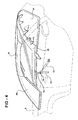
Figure 4 is a perspective view of the convertible top in the extended position; -
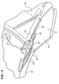
Figure 5 is a bottom perspective view of a portion of the convertible top in the extended position; -
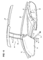
Figure 6 is a perspective view of the convertible top in the partially open position ofFigure 2 ; -
Figure 7 is an enlarged rear perspective view of a portion of the convertible top in the partially open position ofFigure 2 ; -
Figure 8 is an enlarged front perspective view of a portion of the convertible top in the retracted position; and -
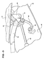
Figure 9 is an enlarged rear perspective view of a portion of the convertible top in the retracted position. - Referring to the figures, a convertible top assembly for a motor vehicle is generally indicated at 10. The
convertible top assembly 10 includes arear panel 20, afront panel 30 and a pair ofouter side panels 40. Thefront panel 30, as shown, is substantially rigid. Thefront panel 30 may, however, be constructed as a frame with a flexible covering. Therear panel 20 may be sized such that a front edge of therear panel 20, that is adjacent to the back edge of thefront panel 30, may also be approximately located in the area front seats of the vehicle, forward of therear seats 82. Thefront panel 30 is movably coupled to therear panel 20 and movable relative to therear panel 20 between an extended position extending between therear panel 20 and awindshield header 12 of thevehicle 10 and a retracted position extending over or stacked relative to therear panel 20. Theouter side panels 40 are movably coupled to therear panel 20 for movement between a use position extending outwardly fromopposite sides rear panel 20 and a stowed position disposed inwardly from the use position. In the illustrated embodiment, the side panels are stowed below therear panel 20. For instance, the rear andfront panels Figs. 1-3 having approximately the same length may be stored in a position in which thefront panel 20 is located above therear panel 30, and in which both outer surfaces of the rear andfront panels convertible top assembly 10 further includes an articulating mechanism operatively connecting therear panel 20,front panel 30 andouter side panels 40 so as to cause movement of theouter side panels 40 between the use position and the stowed position in response to movement of thefront panel 30 between the extended position and the retracted position, respectively. - In
Figures 2-9 , the articulating mechanism is generally indicated at 50. Though only one side of the articulatingmechanism 50 is shown and described below, it should be appreciated that the articulatingmechanism 50 is generally symmetrically opposite about a longitudinal center line of the vehicle. Thearticulating mechanism 50 includes a fourbar linkage 52 pivotally interconnecting therear panel 20 and thefront panel 30. Thelinkage 52 provides the movement of thefront panel 30 relative to therear panel 20 between the extended position and the retracted position. A portion of thearticulating mechanism 50 moves through gaps defined between eachside panel 40 and therear panel 20 during movement of thefront panel 30 between the extended and retracted positions. - One link of the four
bar linkage 52 is a drivinglink 54 that is mechanically coupled to one of theouter side panels 40. In the illustrated embodiment, the drivinglink 54 is the rearmost link of the fourbar linkage 52. A drivenlink 55 operatively connects the drivinglink 54 to the one of theouter side panels 40. More specifically, afirst end 56 of the drivenlink 55 is coupled to the drivinglink 54 by a ball joint. Asecond end 58 of the drivenlink 55 is coupled to aninner surface 42 of the one of theouter side panels 40. More specifically, each of the first 56 and second 58 ends of the drivenlink 55 is pivotally coupled to the drivinglink 54 and theinner surface 42 of the one of theouter side panels 40, respectively, by a ball joint. - An
actuator 60 is operatively coupled to a link of the fourbar linkage 52 to cause movement of thefront panel 30 between the extended and retracted positions. In one embodiment, theactuator 60 is a linear actuator mechanically coupled to the drivinglink 54. Arocker 62 is pivotally coupled to therear panel 20 by alink 63 and to the drivinglink 54 of the fourbar linkage 52. Theactuator 60 is coupled to therocker 62 and rotatably drives therocker 62 to cause corresponding pivotal movement of thefront panel 30 relative to therear panel 20 between the extended and retracted positions. - Referring to
Figure 3 , therear panel 20 is pivotally coupled to a body of the motor vehicle for movement of thetop assembly 10 while thefront panel 30 is in the retracted position between a partially closed position, as indicated by the dotted lines inFigure 3 , wherein a substantial portion of thetop assembly 10 is disposed above a beltline of the motor vehicle, and a fully closed position, as indicated by the solid lines inFigure 3 , wherein thetop assembly 10 is disposed in a rear seat area of the vehicle. - Referring to
Figures 4 and6 , asecond actuator 70 is drivingly coupled to therear panel 20 for driving thetop assembly 10 between the partially closed position and the closed position. Thesecond actuator 70, as illustrated, is a linear actuator. It should be appreciated that other actuators may be used, such as an electric motor. Afirst link 72 is pivotally coupled to thebody 8 of the motor vehicle and asecond link 74 is pivotally coupled to therear panel 20. The first 72 and second 74 links are pivotally coupled to each other by arear pivot 76. Thesecond actuator 70 may be coupled to one of the first 72 and second 74 links or at therear pivot 76, as shown, for driving thetop assembly 10 between the partially closed and closed positions. Further, the first 72 and second 74 links may be movable to an overcenter position to retain therear panel 20 above the beltline of the motor vehicle. - Referring to
Figure 1 , thetop assembly 10 may be disposed in arear seat area 80 of the motor vehicle when thetop assembly 10 is in the closed position. In this case, the motor vehicle may include a rear seat having aseat cushion 84 for supporting a seated occupant and a seat back 82 for supporting the back of the seated occupant. The seat back 82 may be movable between a generally upright use position and a generally horizontal folded flat position overlying theseat cushion 84 so as to accommodate the movement of the convertible top 10 between the closed and open positions. The seat back 82 may also be movable by a variety of mechanisms, such as a linkage, slides and/or any other suitable articulating mechanism or combination thereof. In the particular embodiment illustrated inFigure 1 , the seat back 82 is pivotally coupled to the body of the motor vehicle by a fourbar linkage front surface 86 of the seat back 82 faces the convertible top 10 when the seat back 82 is in the folded flat position and provides a visually appealing surface in case thetop assembly 10 remains in the extended position. - The invention has been described in an illustrative manner. It is, therefore, to be understood that the terminology used is intended to be in the nature of words of description rather than of limitation. Many modifications and variations of the invention are possible in light of the above teachings. For example, the linear actuators in the illustrated embodiment can be replaced by electric motors or other suitable actuators known by those having ordinary skill in the art. Thus, within the scope of the appended claims, the invention may be practiced other than as specifically described.
It is explicitly stated that all features disclosed in the description and/or the claims are intended to be disclosed separately and independently from each other for the purpose of original disclosure as well as for the purpose of restricting the claimed invention independent of the composition of the features in the embodiments and/or the claims. It is explicitly stated that all value ranges or indications of groups of entities disclose every possible intermediate value or intermediate entity for the purpose of original disclosure as well as for the purpose of restricting the claimed invention, in particular as limits of value ranges.
Claims (15)
- A convertible top assembly (10) for a motor vehicle, said convertible top comprising:a rear panel (20);a front panel (30) movably coupled to the rear panel and movable relative to the rear panel (20) between an extended position extending between the rear panel (20) and a windshield header (12) of the vehicle and a retracted position stacked with respect to the rear panel (20);a pair of outer side panels (40) movably coupled to the rear panel (20) for movement between a use position extending outwardly from opposite sides of the rear panel (20) and a stowed position disposed inwardly from the use position; andan articulating mechanism (50) operatively connecting the outer side panels (40) and the front panel (30) so as to cause movement of the outer side panels (40) between the use position and the stowed position in response to movement of the front panel (30) between the extended position and the retracted position, respectively.
- The convertible top assembly (10) as set forth in claim 1, wherein the articulating mechanism (50) includes a four bar linkage (52) pivotally interconnecting the front panel (30) and the rear panel (20), the four bar linkage (52) providing movement of the front panel (30) relative to the rear panel (20) between the extended position and the retracted position.
- The convertible top assembly (10) as set forth in claim 2, wherein the four bar linkage (52) includes a driving link (54) mechanically coupled to one of the outer side panels (40) to cause the movement of the one of the outer side panels (40) between the use and stowed positions in response to the movement of the front panel (30) between the closed and retracted positions, respectively.
- The convertible top assembly (10) as set forth in claim 3, wherein the articulating mechanism (50) includes a driven link (55) having a first end pivotally coupled to the driving link (56) and an opposite second end pivotally coupled to the one of the outer side panels (40), each of the first and second ends of the driven link (55) being pivotally coupled to the driving link (54) and the one of the outer side panels (40), respectively, by a ball joint, the driving link (54) being the rearmost link of the four bar linkage (52).
- The convertible top assembly (10) as set forth in any of claims 2-4, including:a linear actuator (60) driving a link of the four bar linkage (52) to cause movement of the front panel (30) between the closed and retracted positions; anda rocker (62) pivotally coupled to both the rear panel (20) and the driving link (54) of the four bar linkage (52).
- The convertible top assembly (10) as set forth in claim 5, wherein the linear actuator (60) is coupled to the rocker (42) and rotatably drives the rocker (62) to cause corresponding pivotal movement of the front panel (30) relative to the rear panel (20) between the extended and retracted positions.
- The convertible top assembly (10) as set forth in any of claims 1-6 wherein the rear panel (20) is pivotally coupled to a body of the motor vehicle for movement of the convertible top assembly (10) while the front panel (30) is in the retracted position between a partially closed position, wherein the convertible top assembly (10) is disposed above a beltline of the motor vehicle, and a fully closed position.
- The convertible top assembly (10) as set forth in claim 7 including a first link (72) pivotally coupled to the body of the motor vehicle and a second link (74) pivotally coupled to the rear panel (20) the first and second links (72, 74) being pivotally coupled to each other, and a second actuator being drivingly coupled to one of the first and second links (72, 74) for driving the top assembly (10) between the partially closed and fully closed positions.
- The convertible top assembly (10) as set forth in claim 8, wherein the first and second links (72, 74) are movable to an overcenter position to retain the top assembly (10) above the beltline of the motor vehicle.
- The convertible top assembly (10) as set forth in any of claims 1-9, wherein a front edge of the rear panel (20) is disposed adjacent front seats in the vehicle when the top assembly (10) is in the fully closed position.
- The convertible top assembly (10) as set forth in any of claims 1-10, wherein a portion of the articulating mechanism (50) moves through gaps defined between each side panel (40) and the rear panel (20) during movement of the front panel (30) between the extended and retracted positions.
- The convertible top assembly (10) as set forth in any of claims 1-11, wherein the outer side panels (40) and the rear panel (20) have substantially the same front to rear length.
- The convertible top assembly (10) as set forth in any of claims 1-12, wherein the front panel (30) is disposed above the rear panel (20) in the retracted position.
- The convertible top assembly (10) as set forth in any of claims 1-13, wherein the front panel (30) and rear panel (20) each have outer surfaces that remain facing upwardly in both the extended and retracted positions.
- The motor vehicle according to any of the preceding claims;
wherein the convertible top (10) is movable between a closed position extending over a passenger compartment in the vehicle and an open position in which a substantial portion of the top is disposed in the passenger compartment in the vehicle; and further comprising:a rear seat having a seat cushion (84) for supporting a seated occupant and a seat back (82) for supporting the back of the seated occupant, the seat back (82) being movable between an upright use position and a folded flat position overlying the seat cushion (84) so as to accommodate the movement of the convertible top (10) between the closed and open positions, wherein the seat back (82) is movably coupled to a body of the motor vehicle by a four-bar linkage (52), and wherein a front surface of the seat back (82) faces the convertible top (10) when the seat back (82) is in the folded flat position.
Priority Applications (1)
| Application Number | Priority Date | Filing Date | Title |
|---|---|---|---|
| EP12171423.2A EP2500195B1 (en) | 2007-12-21 | 2008-12-16 | Convertible top having movable outboard panels |
Applications Claiming Priority (1)
| Application Number | Priority Date | Filing Date | Title |
|---|---|---|---|
| US11/963,187 US7866726B2 (en) | 2007-12-21 | 2007-12-21 | Convertible top having movable outboard panels |
Related Child Applications (1)
| Application Number | Title | Priority Date | Filing Date |
|---|---|---|---|
| EP12171423.2A Division EP2500195B1 (en) | 2007-12-21 | 2008-12-16 | Convertible top having movable outboard panels |
Publications (2)
| Publication Number | Publication Date |
|---|---|
| EP2072307A2 true EP2072307A2 (en) | 2009-06-24 |
| EP2072307A3 EP2072307A3 (en) | 2009-09-02 |
Family
ID=40470021
Family Applications (2)
| Application Number | Title | Priority Date | Filing Date |
|---|---|---|---|
| EP12171423.2A Not-in-force EP2500195B1 (en) | 2007-12-21 | 2008-12-16 | Convertible top having movable outboard panels |
| EP08021783A Withdrawn EP2072307A3 (en) | 2007-12-21 | 2008-12-16 | Convertible top having movable outboard panels |
Family Applications Before (1)
| Application Number | Title | Priority Date | Filing Date |
|---|---|---|---|
| EP12171423.2A Not-in-force EP2500195B1 (en) | 2007-12-21 | 2008-12-16 | Convertible top having movable outboard panels |
Country Status (2)
| Country | Link |
|---|---|
| US (1) | US7866726B2 (en) |
| EP (2) | EP2500195B1 (en) |
Families Citing this family (8)
| Publication number | Priority date | Publication date | Assignee | Title |
|---|---|---|---|---|
| DE102004021576A1 (en) * | 2004-05-03 | 2005-12-01 | Wilhelm Karmann Gmbh | Convertible car |
| DE102004021577A1 (en) * | 2004-05-03 | 2005-12-01 | Wilhelm Karmann Gmbh | Convertible car |
| JP2007261407A (en) * | 2006-03-28 | 2007-10-11 | Webasto Japan Kk | Retractable roof, and vehicle provided with the same |
| US7866726B2 (en) * | 2007-12-21 | 2011-01-11 | Wilhelm Karmann Gmbh | Convertible top having movable outboard panels |
| US9381796B2 (en) * | 2014-11-12 | 2016-07-05 | Kurt P. Vogt | Split hard top convertible for motorized passenger vehicle |
| US10029548B1 (en) * | 2015-10-07 | 2018-07-24 | Mark A. Stadnyk | Adjustable and removable hard top roof system |
| DE102017128136B4 (en) * | 2017-11-28 | 2021-03-25 | Webasto SE | A convertible top, comprising a headliner assembly |
| USD1094494S1 (en) * | 2025-01-09 | 2025-09-23 | Jianxia Gao | Convertible top push rod ball joint |
Citations (2)
| Publication number | Priority date | Publication date | Assignee | Title |
|---|---|---|---|---|
| WO2003086800A1 (en) * | 2002-04-12 | 2003-10-23 | Edscha Cabrio-Dachsysteme Gmbh | Folding top for a cabriolet vehicle |
| DE102004061776A1 (en) | 2004-12-22 | 2006-07-06 | Wilhelm Karmann Gmbh | Convertible vehicle, has roof parts infringing in remote position area wise from movable covering part of body, where one roof part with rear window forms visible outer surface of roof parts over substantial part of its extension |
Family Cites Families (22)
| Publication number | Priority date | Publication date | Assignee | Title |
|---|---|---|---|---|
| DE3903358A1 (en) * | 1989-02-04 | 1990-08-30 | Bayerische Motoren Werke Ag | Retractable vehicle roof |
| USRE38546E1 (en) * | 1993-01-04 | 2004-07-06 | Asc Incorporated | Convertible top |
| IT1278123B1 (en) * | 1994-07-08 | 1997-11-17 | Daimler Benz Ag | VEHICLE WITH ROOF AT LEAST PARTIALLY LOWERING. |
| DE19635536C1 (en) * | 1996-09-02 | 1998-01-22 | Daimler Benz Ag | Movable roof-structure for convertible car |
| FR2778610B1 (en) * | 1998-05-12 | 2000-08-04 | France Design | FOLDABLE ROOF IN THREE ELEMENTS FOR DISCOVERABLE VEHICLE |
| US6419295B1 (en) * | 2001-02-08 | 2002-07-16 | Cts Fahrzeug Dachsysteme Gmbh | Folding top rear quarter window storage system |
| DE10121839A1 (en) * | 2001-05-04 | 2002-11-07 | Porsche Ag | Wind shield for convertible motor vehicle has upper seat back section accommodating it in folded transporting position connected on both longitudinal sides of vehicle to cross member of body by corresponding four-member linkage |
| DE10147015C2 (en) * | 2001-09-25 | 2003-08-07 | Cts Fahrzeug Dachsysteme Gmbh | Multi-part hardtop vehicle roof |
| DE10152944B4 (en) * | 2001-10-26 | 2016-12-15 | Webasto-Edscha Cabrio GmbH | Hood for a convertible vehicle |
| US6866324B2 (en) * | 2002-02-25 | 2005-03-15 | Ssr Roofing Systems, L.L.C. | Folding hardtop with rear window articulation |
| JP3885607B2 (en) * | 2002-02-25 | 2007-02-21 | マツダ株式会社 | Vehicle roof structure |
| US6695378B2 (en) * | 2002-04-22 | 2004-02-24 | Corbin Pacific, Inc. | Vehicle seat with movable backrest |
| US7255385B2 (en) * | 2002-10-18 | 2007-08-14 | Heuliez | Convertible roof for vehicle and associated vehicle |
| FR2865684B1 (en) * | 2004-02-04 | 2006-05-26 | France Design | RETRACTABLE ROOF IN THE REAR ROOF OF A VEHICLE, COMPRISING DISPLACABLE LATERAL ELEMENTS |
| DE102004021576A1 (en) * | 2004-05-03 | 2005-12-01 | Wilhelm Karmann Gmbh | Convertible car |
| FR2882001B1 (en) | 2005-02-17 | 2012-12-21 | Heuliez | MOTOR VEHICLE COMPRISING A RECTANGULAR ROOF AND MOBILE SIDE VITREES IN RELATION TO THE ROOF |
| GB2427593A (en) * | 2005-06-29 | 2007-01-03 | Ford Global Tech Llc | Folding roof for a motor vehicle |
| DE102005055583B4 (en) | 2005-11-18 | 2008-01-24 | Magna Car Top Systems Gmbh | Vehicle with an adjustable vehicle roof |
| DE102006016486B3 (en) * | 2006-04-07 | 2007-10-11 | Daimlerchrysler Ag | Hardtop folding top for an open car |
| US7494175B2 (en) * | 2006-06-28 | 2009-02-24 | Ford Global Technologies, Llc | Motor vehicle |
| DE102006038769A1 (en) * | 2006-08-17 | 2008-02-21 | Wilhelm Karmann Gmbh | Cabriolet vehicle, has roof sections with outer surfaces, and roof moved along with middle section from common plane such that edge sections are displaced partially downwards with respect to middle section when roof is opened |
| US7866726B2 (en) * | 2007-12-21 | 2011-01-11 | Wilhelm Karmann Gmbh | Convertible top having movable outboard panels |
-
2007
- 2007-12-21 US US11/963,187 patent/US7866726B2/en not_active Expired - Fee Related
-
2008
- 2008-12-16 EP EP12171423.2A patent/EP2500195B1/en not_active Not-in-force
- 2008-12-16 EP EP08021783A patent/EP2072307A3/en not_active Withdrawn
Patent Citations (2)
| Publication number | Priority date | Publication date | Assignee | Title |
|---|---|---|---|---|
| WO2003086800A1 (en) * | 2002-04-12 | 2003-10-23 | Edscha Cabrio-Dachsysteme Gmbh | Folding top for a cabriolet vehicle |
| DE102004061776A1 (en) | 2004-12-22 | 2006-07-06 | Wilhelm Karmann Gmbh | Convertible vehicle, has roof parts infringing in remote position area wise from movable covering part of body, where one roof part with rear window forms visible outer surface of roof parts over substantial part of its extension |
Also Published As
| Publication number | Publication date |
|---|---|
| EP2500195A1 (en) | 2012-09-19 |
| US7866726B2 (en) | 2011-01-11 |
| US20090160207A1 (en) | 2009-06-25 |
| EP2072307A3 (en) | 2009-09-02 |
| EP2500195B1 (en) | 2013-07-31 |
Similar Documents
| Publication | Publication Date | Title |
|---|---|---|
| EP1567379B1 (en) | Folding top for vehicle with rigid rear panel | |
| EP2500195B1 (en) | Convertible top having movable outboard panels | |
| US6866324B2 (en) | Folding hardtop with rear window articulation | |
| US6666495B2 (en) | Retractable top system for vehicles with movable rear section | |
| US6736445B2 (en) | Top for a convertible vehicle | |
| US6419295B1 (en) | Folding top rear quarter window storage system | |
| US7621583B2 (en) | Retractable hardtop with extended buttresses and an active rear window | |
| US6659533B1 (en) | Vehicle convertible roof | |
| US7922232B2 (en) | Movable multisection roof for a motor vehicle | |
| US7014247B2 (en) | Hardtop convertible | |
| US7063371B2 (en) | Convertible hardtop roof | |
| US6755457B2 (en) | Vehicle convertible roof | |
| US6557921B2 (en) | Hardtop vehicle roof movable between closed and open positions | |
| EP1555152B1 (en) | Mechanism for use with both hard and hybrid retractable cabrilolet vehicle tops | |
| US7845704B2 (en) | Transparent outer panel for a retractable hardtop | |
| US6964340B2 (en) | Retractable hardtop with articulating center panel | |
| US7819461B2 (en) | Convertible top with trim covered panels | |
| US7708332B2 (en) | Convertible roof system | |
| US7758101B2 (en) | Roof structure for a rigid, openable vehicle roof | |
| US20070090664A1 (en) | Hardtop vehicle roof with external roof kinematic system |
Legal Events
| Date | Code | Title | Description |
|---|---|---|---|
| PUAI | Public reference made under article 153(3) epc to a published international application that has entered the european phase |
Free format text: ORIGINAL CODE: 0009012 |
|
| AK | Designated contracting states |
Kind code of ref document: A2 Designated state(s): AT BE BG CH CY CZ DE DK EE ES FI FR GB GR HR HU IE IS IT LI LT LU LV MC MT NL NO PL PT RO SE SI SK TR |
|
| AX | Request for extension of the european patent |
Extension state: AL BA MK RS |
|
| PUAL | Search report despatched |
Free format text: ORIGINAL CODE: 0009013 |
|
| AK | Designated contracting states |
Kind code of ref document: A3 Designated state(s): AT BE BG CH CY CZ DE DK EE ES FI FR GB GR HR HU IE IS IT LI LT LU LV MC MT NL NO PL PT RO SE SI SK TR |
|
| AX | Request for extension of the european patent |
Extension state: AL BA MK RS |
|
| 19U | Interruption of proceedings before grant |
Effective date: 20090629 |
|
| 19W | Proceedings resumed before grant after interruption of proceedings |
Effective date: 20101201 |
|
| 17P | Request for examination filed |
Effective date: 20101201 |
|
| 17Q | First examination report despatched |
Effective date: 20110114 |
|
| AKX | Designation fees paid |
Designated state(s): AT BE BG CH CY CZ DE DK EE ES FI FR GB GR HR HU IE IS IT LI LT LU LV MC MT NL NO PL PT RO SE SI SK TR |
|
| STAA | Information on the status of an ep patent application or granted ep patent |
Free format text: STATUS: THE APPLICATION IS DEEMED TO BE WITHDRAWN |
|
| 18D | Application deemed to be withdrawn |
Effective date: 20120703 |