EP2072174A1 - Friction stir spot joining device - Google Patents
Friction stir spot joining device Download PDFInfo
- Publication number
- EP2072174A1 EP2072174A1 EP08022040A EP08022040A EP2072174A1 EP 2072174 A1 EP2072174 A1 EP 2072174A1 EP 08022040 A EP08022040 A EP 08022040A EP 08022040 A EP08022040 A EP 08022040A EP 2072174 A1 EP2072174 A1 EP 2072174A1
- Authority
- EP
- European Patent Office
- Prior art keywords
- stirring
- joining device
- friction stir
- spot joining
- stir spot
- Prior art date
- Legal status (The legal status is an assumption and is not a legal conclusion. Google has not performed a legal analysis and makes no representation as to the accuracy of the status listed.)
- Granted
Links
Images


Classifications
-
- B—PERFORMING OPERATIONS; TRANSPORTING
- B23—MACHINE TOOLS; METAL-WORKING NOT OTHERWISE PROVIDED FOR
- B23K—SOLDERING OR UNSOLDERING; WELDING; CLADDING OR PLATING BY SOLDERING OR WELDING; CUTTING BY APPLYING HEAT LOCALLY, e.g. FLAME CUTTING; WORKING BY LASER BEAM
- B23K20/00—Non-electric welding by applying impact or other pressure, with or without the application of heat, e.g. cladding or plating
- B23K20/12—Non-electric welding by applying impact or other pressure, with or without the application of heat, e.g. cladding or plating the heat being generated by friction; Friction welding
- B23K20/122—Non-electric welding by applying impact or other pressure, with or without the application of heat, e.g. cladding or plating the heat being generated by friction; Friction welding using a non-consumable tool, e.g. friction stir welding
- B23K20/1265—Non-butt welded joints, e.g. overlap-joints, T-joints or spot welds
-
- B—PERFORMING OPERATIONS; TRANSPORTING
- B23—MACHINE TOOLS; METAL-WORKING NOT OTHERWISE PROVIDED FOR
- B23K—SOLDERING OR UNSOLDERING; WELDING; CLADDING OR PLATING BY SOLDERING OR WELDING; CUTTING BY APPLYING HEAT LOCALLY, e.g. FLAME CUTTING; WORKING BY LASER BEAM
- B23K20/00—Non-electric welding by applying impact or other pressure, with or without the application of heat, e.g. cladding or plating
- B23K20/12—Non-electric welding by applying impact or other pressure, with or without the application of heat, e.g. cladding or plating the heat being generated by friction; Friction welding
- B23K20/122—Non-electric welding by applying impact or other pressure, with or without the application of heat, e.g. cladding or plating the heat being generated by friction; Friction welding using a non-consumable tool, e.g. friction stir welding
- B23K20/1245—Non-electric welding by applying impact or other pressure, with or without the application of heat, e.g. cladding or plating the heat being generated by friction; Friction welding using a non-consumable tool, e.g. friction stir welding characterised by the apparatus
- B23K20/125—Rotary tool drive mechanism
-
- B—PERFORMING OPERATIONS; TRANSPORTING
- B23—MACHINE TOOLS; METAL-WORKING NOT OTHERWISE PROVIDED FOR
- B23K—SOLDERING OR UNSOLDERING; WELDING; CLADDING OR PLATING BY SOLDERING OR WELDING; CUTTING BY APPLYING HEAT LOCALLY, e.g. FLAME CUTTING; WORKING BY LASER BEAM
- B23K37/00—Auxiliary devices or processes, not specially adapted for a procedure covered by only one of the other main groups of this subclass
- B23K37/02—Carriages for supporting the welding or cutting element
Definitions
- the invention relates a friction stir spot joining device for softening and stirring an object to be joined by frictional heat generated by rotation of a pin so as to perform spot joining, and provided with a stirring motor for rotating the pin and a pressure application motor for driving the pin to be moved straight.
- a friction stir spot joining device for softening and stirring an object to be joined by frictional heat generated by rotation of a center pin and a shoulder pin so as to perform spot joining, and provided with a stirring motor for rotating the shoulder pin in which the center pin is inserted, a motor for driving the center pin for causing the center pin alone to be retracted, and a pressure application motor, wherein a shaft of the shoulder pin and the stirring motor are connected to each other by a power transmission mechanism, and a shaft of the center pin and the motor for driving the center pin are connected to each other by another power transmission mechanism so as to integrate stirring-related members, and bearings of an LM guide (registered trademark) are fixed to a lower portion of the power transmission mechanism for the center pin behind thereof, a ball nut is fixed to the back face of the integrated stirring-related members, and the pressure application motor is fixed to a friction stir spot joining device body to which rails of the LM guide (registered trademark) are fixed and which contains therein the integrated stirring-related members, and wherein
- Patent Document 2 since it adopts a configuration wherein the stirring-related members are integrated, and the pin and the stirring motor are moved at the same time inside the friction stir spot joining device body relative to the pressure application motor fixed to the friction stir spot joining device body side, the problem of Patent Document 1 is tentatively solved by the configuration of the friction stir spot joining device disclosed in Patent Document 2.
- the integrated stirring-related members are entirely contained in the friction stir spot joining device body, when performing maintenance or assembly of the stirring-related members, the stirring-related members are difficult to be taken out and assembled, and the stirring motor and the power transmission mechanism for the stirring motor can not be solely removed or replaced.
- the present invention has been made in view of the problems of the foregoing conventional techniques, and it is therefore an object of the invention to provide a friction stir spot joining device which unitizes stirring-related members to form a stirring unit, and forms an opening in a friction stir spot joining device body (hereinafter referred to a joining device body) for housing therein the stirring unit, so that the stirring unit becomes light in weight and has a general versatility with a simple structure, and it can be moved with assurance, and the components thereof can be removed with ease.
- a friction stir spot joining device which unitizes stirring-related members to form a stirring unit, and forms an opening in a friction stir spot joining device body (hereinafter referred to a joining device body) for housing therein the stirring unit, so that the stirring unit becomes light in weight and has a general versatility with a simple structure, and it can be moved with assurance, and the components thereof can be removed with ease.
- a friction stir spot joining device for softening and stirring an object to be joined by frictional heat generated by rotation of a pin 1 so as to perform spot joining, according to the first aspect of the invention, comprises a fixed arm 4; a friction stir spot joining device body 6 connected to the fixed arm 4 and incorporating therein a stirring shaft 13 supported by bearings 11 and having the pin 1 at the tip end and a hole 12 at the center thereof through which a screw shaft 9 can be housed from the rear, a stirring motor 10 for rotating the stirring shaft 13, a power transmission mechanism 14 disposed between the stirring shaft 13 and the stirring motor 10, and provided with rails 21 of an LM guide (registered trademark) provided at a bottom plate thereof; and a pressure application motor 7 fixed to a rear end of the friction stir spot joining device body 6; wherein the stirring motor 10, the stirring shaft 13 and the power transmission mechanism 14 are unitized to form a stirring unit, and bearings 19 of the LM guide (registered trademark) are fixed to the stirring unit immediately under the stirring unit, and a
- the friction stir spot joining device is characterized in that the power transmission mechanism 14 comprises a toothed pulley 15 and a toothed belt, and lateral split type bearings 19, 19 of the LM guide (registered trademark) are disposed immediately under the toothed pulley 15.
- the power transmission mechanism 14 comprises a toothed pulley 15 and a toothed belt
- lateral split type bearings 19, 19 of the LM guide registered trademark
- the friction stir spot joining device With the configuration of the friction stir spot joining device according to the first aspect of the invention, a burden applied to the bearings of the LM guide (registered trademark) is reduced, thereby restraining the vibration at the pin side, and the components of the stirring unit can be removed and replaced with ease, so that the friction stir spot joining device can be light in weight as a whole.
- LM guide registered trademark
- the transmission of the power from the stirring motor to the stirring shaft is assured and the LM guide (registered trademark) can be disposed to approach a portion immediately under the toothed pulley, so that the generation of falling torque relative to the LM guide (registered trademark) caused by stirring torque is prevented and a distance from the center of the stirring shaft to the bottom face of the joining device body can be minimized, thereby restraining the friction stir spot joining device from increasing in height.
- the LM guide registered trademark
- Fig. 1 is a view showing a schematic configuration of a friction stir spot joining adapted for working the present invention.
- the friction stir spot joining device for softening and stirring an object to be joined by frictional heat generated by rotation of a pin so as to perform spot joining, wherein the stirring motor 10, a stirring shaft 13 supported by bearings 11 and having the pin 1 at the tip end and a hole 12 at the center thereof through which a screw shaft 9 can be housed from the rear, and a power transmission mechanism 14 disposed between the stirring motor 10 and the stirring shaft 13 are unitized to form a stirring unit, and bearings 19, 19 of an LM guide (registered trademark) are fixed to the stirring unit immediately under the stirring unit, a ball nut 16 is fixed to the back face of the stirring unit, and a friction stir spot joining device body to which rails 21 of the LM guide (registered trademark) are fixed has a rear upper portion being opened through which the stirring unit is caused to move inside thereof, and a rear end thereof to which the pressure application motor
- LM guide registered trademark
- the power transmission mechanism 14 comprises a toothed pulley 15 and a toothed belt, and lateral split type bearings 19, 19 of the LM guide (registered trademark) are disposed immediately under the toothed pulley 15.
- the pin 1 is inserted in a joining point of an object to be joined (not shown), and a part of the object to be joined is softened and stirred by the frictional heat caused by rotation of the pin 1, thereby performing spot joining.
- the friction stir spot joining device is roughly structured as follows.
- a holding jig 5 for holding the object to be joined is disposed at the tip end of a fixed arm 4 which is fitted to a wrist 2 of a robot by way of a bracket 3, and a joining device body 6 is fixedly secured to a rear end portion of the fixed arm 4.
- the pressure application motor 7 is fixedly secured to a rear end portion of the joining device body 6 and the screw shaft 9 is fixedly secured to an output shaft 8 of the pressure application motor 7.
- the stirring motor 10 for rotating the pin 1, a stirring shaft 13 having the pin 1 at the tip end, and supported by the bearings 11 and provided with the hole 12 at the center through which the screw shaft 9 can be housed from the rear, and the power transmission mechanism 14 comprised of, e.g. a belt and a pulley and disposed between the stirring shaft 13 and the stirring motor 10 are unitized and incorporated in the joining device body 6 as the stirring unit.
- the pulley 15 for a belt of the power transmission mechanism 14 is fixedly secured to the rear portion of the stirring shaft 13, and the ball nut 16 is fixedly secured to the opening of the hole 12 coaxially with the hole 2.
- An upwardly extended support member 18 for supporting the stirring motor 10 is fixedly secured to the rear end portion of a driving unit boy 17 for holding outer rings of the bearings 11 of the stirring shaft 13.
- the bearings 19, 19 of the LM guide are fixedly secured to the lower portion of the driving unit boy 17 immediately under the driving unit boy 17.
- Rails 21 for guiding the movement of the bearings 19, 19 of the LM guide (registered trademark) are provided on a bottom plate 20 of the joining device body 6 for a length exceeding a moving stroke of the bearings 19, 19 of the LM guide (registered trademark), and an upper face and both side faces of the joining device body 6 are opened to form an opening so as to cause the stirring motor 10 to be exposed outside.
- the stirring motor 10 having the opening so as to be exposed outside, the stirring motor 10 and the power transmission mechanism 14 can be easily taken out from these openings.
- Depicted by 22 is a pressure ring for pressing the front part of the outer rings of the bearings 11.
- Depicted by 23 is bearings disposed at the rear portion of the screw shaft 9 and journaling the screw shaft 9.
- Depicted by 24 is a coupling for connecting between the output shaft 8 of the pressure application motor 7 and the screw shaft 9.
- the entire friction stir spot joining device is first moved by the robot 2 to a position opposing an intended joining point of the object to be joined.
- the stirring motor 10 and the pressure application motor 7 are driven at the position opposing the intended joining point, thereby causing the ball nut 16 to advance by the pressure application motor 7, so that the driving unit boy 17 is guided by the LM guide (registered trademark) to advance toward the intended joining point while accompanied with the stirring motor 10, and the pin 1 is rotated together with the stirring shaft 13 by the stirring motor 10.
- LM guide registered trademark
- the pin 1 is caused to pass through the surface of the object to be joined and inserted therein by the pressure application motor 7 and it is rendered in a state of rotation at the joining point of the object to be joined. At this point in time, the driving of pressure application motor 7 is stopped to stop the advance of the pin 1. However, the pin 1 frictions the object to be joined by rotation of the pin 1 to dissolve a part of the object to be joined and stir and stir the dissolved matter, and the dissolved matter performs a spot joining of the object to be joined.
- the pressure application motor 7 is inversely rotated. With the inverse rotation of the pressure application motor 7, the pin 1 continues its rotation to stir the object to be joined and is taken out from the joining point of the object to be joined.
- the driving unit boy 17 When the pressure application motor 7 is inversely driven by the inverse rotation, the driving unit boy 17 is guided by the LM guide (registered trademark) while accompanied with the stirring motor 10, and is retracted from the joining point side of the object to be joined, and is returned to a state prior to the joining operation.
- LM guide registered trademark
- the stirring motor 10 since the stirring motor 10 is moved together with the driving unit boy 17, there is no obstacle in the power transmission from the stirring motor 10 to the stirring shaft 13. Further, since the stirring motor 10, the stirring shaft 13 supported by bearings 11 and having the pin 1 at the tip end and the hole 12 through which the screw shaft 9 can be housed from the rear portion thereof, and the power transmission mechanism 14 are unitized to form the stirring unit, and bearings 19, 19 of LM guide (registered trademark) are fixed to the stirring unit immediately under the stirring unit, the stirring unit has a general versatility with a simple structure, and it can be moved while guided by the LM guide (registered trademark) with assurance. Further, since the joining device body has the opening at the rear upper portion for causing the stirring unit to be moved therein, the components of the stirring unit are removable and replaceable with ease, and the friction stir spot joining device becomes light in weight as a whole.
- the power transmission mechanism 14 is configured to be comprised of a toothed pulley 15 and a toothed belt, and lateral split type bearings 19, 19 of an LM guide (registered trademark) are disposed immediately under the toothed pulley 15.
- LM guide registered trademark
Landscapes
- Engineering & Computer Science (AREA)
- Mechanical Engineering (AREA)
- Physics & Mathematics (AREA)
- Optics & Photonics (AREA)
- Pressure Welding/Diffusion-Bonding (AREA)
Abstract
Description
- The invention relates a friction stir spot joining device for softening and stirring an object to be joined by frictional heat generated by rotation of a pin so as to perform spot joining, and provided with a stirring motor for rotating the pin and a pressure application motor for driving the pin to be moved straight.
- There has been conventionally a friction stir spot joining device for softening and stirring an object to be joined by frictional heat generated by rotation of a pin so as to perform spot joining, and provided with a stirring motor for rotating the pin and a pressure application motor for driving the pin to be moved straight (for example, see Patent Document 1).
- There has been also a friction stir spot joining device for softening and stirring an object to be joined by frictional heat generated by rotation of a center pin and a shoulder pin so as to perform spot joining, and provided with a stirring motor for rotating the shoulder pin in which the center pin is inserted, a motor for driving the center pin for causing the center pin alone to be retracted, and a pressure application motor, wherein a shaft of the shoulder pin and the stirring motor are connected to each other by a power transmission mechanism, and a shaft of the center pin and the motor for driving the center pin are connected to each other by another power transmission mechanism so as to integrate stirring-related members, and bearings of an LM guide (registered trademark) are fixed to a lower portion of the power transmission mechanism for the center pin behind thereof, a ball nut is fixed to the back face of the integrated stirring-related members, and the pressure application motor is fixed to a friction stir spot joining device body to which rails of the LM guide (registered trademark) are fixed and which contains therein the integrated stirring-related members, and wherein the screw shaft connected to the pressure application motor is caused to screw with the ball nut so as to advance or retract the integrated stirring-related members (for example, see Patent Document 2).
- [Patent Document 1]
JP 2002-35960A - [Patent Document 2]
JP 2007-216249A - According to the friction stir spot joining device described in
Patent Document 1, since the stirring motor for rotating the pin is fixed to the friction stir spot joining device body side like the pressure application motor, when the pin is driven so as to be moved straight, there occurs a phase difference in a positional relation between the stirring motor and the pin, so that a spline mechanism is adopted for transmitting the rotary motion of the stirring motor to the pin. Owing to the spline mechanism, a straight moving stroke of the pin is restricted by the length of a groove of the spline and there is a possibility that the entire friction stir spot joining device is large sized. - According to the friction stir spot joining device described in
Patent Document 2, since it adopts a configuration wherein the stirring-related members are integrated, and the pin and the stirring motor are moved at the same time inside the friction stir spot joining device body relative to the pressure application motor fixed to the friction stir spot joining device body side, the problem ofPatent Document 1 is tentatively solved by the configuration of the friction stir spot joining device disclosed inPatent Document 2. However, since the integrated stirring-related members are entirely contained in the friction stir spot joining device body, when performing maintenance or assembly of the stirring-related members, the stirring-related members are difficult to be taken out and assembled, and the stirring motor and the power transmission mechanism for the stirring motor can not be solely removed or replaced. Further, since the bearings of the LM guide (registered trademark) are fixed to the lower portion of the power transmission mechanism behind thereof, a large burden is applied to the bearings of the LM guide (registered trademark), causing a problem that the pin side is liable to vibrate and so forth. - The present invention has been made in view of the problems of the foregoing conventional techniques, and it is therefore an object of the invention to provide a friction stir spot joining device which unitizes stirring-related members to form a stirring unit, and forms an opening in a friction stir spot joining device body (hereinafter referred to a joining device body) for housing therein the stirring unit, so that the stirring unit becomes light in weight and has a general versatility with a simple structure, and it can be moved with assurance, and the components thereof can be removed with ease.
- To achieve the above object, a friction stir spot joining device for softening and stirring an object to be joined by frictional heat generated by rotation of a
pin 1 so as to perform spot joining, according to the first aspect of the invention, comprises afixed arm 4; a friction stir spot joiningdevice body 6 connected to thefixed arm 4 and incorporating therein a stirringshaft 13 supported bybearings 11 and having thepin 1 at the tip end and ahole 12 at the center thereof through which ascrew shaft 9 can be housed from the rear, a stirringmotor 10 for rotating the stirringshaft 13, apower transmission mechanism 14 disposed between the stirringshaft 13 and the stirringmotor 10, and provided withrails 21 of an LM guide (registered trademark) provided at a bottom plate thereof; and apressure application motor 7 fixed to a rear end of the friction stir spot joiningdevice body 6; wherein the stirringmotor 10, the stirringshaft 13 and thepower transmission mechanism 14 are unitized to form a stirring unit, andbearings 19 of the LM guide (registered trademark) are fixed to the stirring unit immediately under the stirring unit, and aball nut 16 is fixed to the back face of the stirring unit, wherein the friction stir spot joiningdevice body 6 is opened to form an opening at a rear upper portion through which the stirring unit is caused to move inside thereof; and wherein thescrew shaft 9 connected to thepressure application motor 7 is caused to screw with theball nut 16 fixed to the back face of the stirring unit so as to advance or retract the stirring unit by thepressure application motor 7. - The friction stir spot joining device according to the second aspect of the invention is characterized in that the
power transmission mechanism 14 comprises atoothed pulley 15 and a toothed belt, and lateralsplit type bearings toothed pulley 15. - With the configuration of the friction stir spot joining device according to the first aspect of the invention, a burden applied to the bearings of the LM guide (registered trademark) is reduced, thereby restraining the vibration at the pin side, and the components of the stirring unit can be removed and replaced with ease, so that the friction stir spot joining device can be light in weight as a whole.
- With the configuration of the friction stir spot joining device according to the second aspect of the invention, the transmission of the power from the stirring motor to the stirring shaft is assured and the LM guide (registered trademark) can be disposed to approach a portion immediately under the toothed pulley, so that the generation of falling torque relative to the LM guide (registered trademark) caused by stirring torque is prevented and a distance from the center of the stirring shaft to the bottom face of the joining device body can be minimized, thereby restraining the friction stir spot joining device from increasing in height.
-
-
Fig. 1 is a view showing a schematic configuration of a friction stir spot joining device of the invention; -
Fig. 2 is a schematic view as viewed from the arrow A-A inFig. 1 ; and -
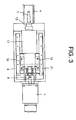
Fig. 3 is a schematic view as viewed from the arrow B-B inFig. 1 . -
Fig. 1 is a view showing a schematic configuration of a friction stir spot joining adapted for working the present invention. The friction stir spot joining device, according to the first aspect of the invention, for softening and stirring an object to be joined by frictional heat generated by rotation of a pin so as to perform spot joining, wherein the stirringmotor 10, astirring shaft 13 supported bybearings 11 and having thepin 1 at the tip end and ahole 12 at the center thereof through which ascrew shaft 9 can be housed from the rear, and apower transmission mechanism 14 disposed between the stirringmotor 10 and the stirringshaft 13 are unitized to form a stirring unit, andbearings ball nut 16 is fixed to the back face of the stirring unit, and a friction stir spot joining device body to whichrails 21 of the LM guide (registered trademark) are fixed has a rear upper portion being opened through which the stirring unit is caused to move inside thereof, and a rear end thereof to which thepressure application motor 7 is fixed, and wherein the screwshaft screw shaft 9 connected to thepressure application motor 7 is caused to screw with theball nut 16 fixed to the back face of the stirring unit so as to advance or retract the stirring unit. - In the friction stir spot joining device of the second aspect of the invention, the
power transmission mechanism 14 comprises atoothed pulley 15 and a toothed belt, and lateralsplit type bearings toothed pulley 15. - In the friction stir spot joining device, the
pin 1 is inserted in a joining point of an object to be joined (not shown), and a part of the object to be joined is softened and stirred by the frictional heat caused by rotation of thepin 1, thereby performing spot joining. The friction stir spot joining device is roughly structured as follows. - A
holding jig 5 for holding the object to be joined is disposed at the tip end of a fixedarm 4 which is fitted to awrist 2 of a robot by way of abracket 3, and a joiningdevice body 6 is fixedly secured to a rear end portion of thefixed arm 4. Thepressure application motor 7 is fixedly secured to a rear end portion of the joiningdevice body 6 and thescrew shaft 9 is fixedly secured to anoutput shaft 8 of thepressure application motor 7. - The stirring
motor 10 for rotating thepin 1, astirring shaft 13 having thepin 1 at the tip end, and supported by thebearings 11 and provided with thehole 12 at the center through which thescrew shaft 9 can be housed from the rear, and thepower transmission mechanism 14 comprised of, e.g. a belt and a pulley and disposed between the stirringshaft 13 and the stirringmotor 10 are unitized and incorporated in the joiningdevice body 6 as the stirring unit. - The
pulley 15 for a belt of thepower transmission mechanism 14 is fixedly secured to the rear portion of thestirring shaft 13, and theball nut 16 is fixedly secured to the opening of thehole 12 coaxially with thehole 2. An upwardly extendedsupport member 18 for supporting the stirringmotor 10 is fixedly secured to the rear end portion of a drivingunit boy 17 for holding outer rings of thebearings 11 of the stirringshaft 13. Thebearings driving unit boy 17 immediately under thedriving unit boy 17. -
Rails 21 for guiding the movement of thebearings bottom plate 20 of the joiningdevice body 6 for a length exceeding a moving stroke of thebearings device body 6 are opened to form an opening so as to cause the stirringmotor 10 to be exposed outside. With the stirringmotor 10 having the opening so as to be exposed outside, the stirringmotor 10 and thepower transmission mechanism 14 can be easily taken out from these openings. - Depicted by 22 is a pressure ring for pressing the front part of the outer rings of the
bearings 11. Depicted by 23 is bearings disposed at the rear portion of thescrew shaft 9 and journaling thescrew shaft 9. Depicted by 24 is a coupling for connecting between theoutput shaft 8 of thepressure application motor 7 and thescrew shaft 9. - With the friction stir spot joining device having the foregoing configuration, the entire friction stir spot joining device is first moved by the
robot 2 to a position opposing an intended joining point of the object to be joined. - The stirring
motor 10 and thepressure application motor 7 are driven at the position opposing the intended joining point, thereby causing theball nut 16 to advance by thepressure application motor 7, so that the drivingunit boy 17 is guided by the LM guide (registered trademark) to advance toward the intended joining point while accompanied with the stirringmotor 10, and thepin 1 is rotated together with the stirringshaft 13 by the stirringmotor 10. - The
pin 1 is caused to pass through the surface of the object to be joined and inserted therein by thepressure application motor 7 and it is rendered in a state of rotation at the joining point of the object to be joined. At this point in time, the driving ofpressure application motor 7 is stopped to stop the advance of thepin 1. However, thepin 1 frictions the object to be joined by rotation of thepin 1 to dissolve a part of the object to be joined and stir and stir the dissolved matter, and the dissolved matter performs a spot joining of the object to be joined. - Upon completion of the foregoing joining operation, the
pressure application motor 7 is inversely rotated. With the inverse rotation of thepressure application motor 7, thepin 1 continues its rotation to stir the object to be joined and is taken out from the joining point of the object to be joined. - When the
pressure application motor 7 is inversely driven by the inverse rotation, thedriving unit boy 17 is guided by the LM guide (registered trademark) while accompanied with the stirringmotor 10, and is retracted from the joining point side of the object to be joined, and is returned to a state prior to the joining operation. - As mentioned in detail above, with the friction stir spot joining device of the present invention, since the
stirring motor 10 is moved together with thedriving unit boy 17, there is no obstacle in the power transmission from the stirringmotor 10 to the stirringshaft 13. Further, since the stirringmotor 10, thestirring shaft 13 supported bybearings 11 and having thepin 1 at the tip end and thehole 12 through which thescrew shaft 9 can be housed from the rear portion thereof, and thepower transmission mechanism 14 are unitized to form the stirring unit, andbearings - The
power transmission mechanism 14 according to the first example is configured to be comprised of atoothed pulley 15 and a toothed belt, and lateralsplit type bearings toothed pulley 15. - As a result, power transmission from a stirring
motor 10 to a stirringshaft 13 is performed with assurance, and the LM guide (registered trademark) can be disposed at a portion closer than a portion immediately under thetoothed pulley 15, so that falling torque relative to the LM guide (registered trademark) caused by stirring torque is not generated. Further, it is possible to minimize a distance from the center of the stirringshaft 13 to abottom plate 20 of a joiningdevice body 6.
The features disclosed in the foregoing description, in the claims and/or in the accompanying drawings may, both separately and in any combination thereof, be material for realising the invention in diverse forms thereof.
Claims (2)
- A friction stir spot joining device for softening and stirring an object to be joined by frictional heat generated by rotation of a pin (1) so as to perform spot joining, said friction stir spot joining device comprising a fixed arm (4); a friction stir spot joining device body (6) connected to the fixed arm (4) and incorporating therein a stirring shaft (13) supported by bearings (11) and having the pin (1) at the tip end and a hole (12) at the center thereof through which a screw shaft (9) can be housed from the rear, a stirring motor (10) for rotating the stirring shaft (13), a power transmission mechanism (14) disposed between the stirring shaft (13) and the stirring motor (10), and provided with rails (21) of an LM guide (registered trademark) provided at a bottom plate thereof; and a pressure application motor (7) fixed to a rear end of the friction stir spot joining device body (6);
characterized in that the stirring motor (10), the stirring shaft (13) and the power transmission mechanism (14) are unitized to form a stirring unit, and bearings (19, 19) of the LM guide (registered trademark) are fixed to the stirring unit immediately under the stirring unit, and a ball nut (16) is fixed to the back face of the stirring unit;
wherein the friction stir spot joining device body (6) is opened to form an opening at a rear upper portion through which the stirring unit is caused to move inside thereof; and
wherein the screw shaft (9) connected to the pressure application motor (7) is caused to screw with the ball nut (16) fixed to the back face of the stirring unit so as to advance or retract the stirring unit by the pressure application motor (7). - The friction stir spot joining device according to Claim 1, wherein the power transmission mechanism (14) comprises a toothed pulley (15) and a toothed belt, and lateral split type bearings (19, 19) of the LM guide (registered trademark) are disposed immediately under the toothed pulley (15).
Applications Claiming Priority (1)
| Application Number | Priority Date | Filing Date | Title |
|---|---|---|---|
| JP2007329490A JP5081609B2 (en) | 2007-12-21 | 2007-12-21 | Friction stir spot welding equipment |
Publications (2)
| Publication Number | Publication Date |
|---|---|
| EP2072174A1 true EP2072174A1 (en) | 2009-06-24 |
| EP2072174B1 EP2072174B1 (en) | 2016-05-04 |
Family
ID=40469904
Family Applications (1)
| Application Number | Title | Priority Date | Filing Date |
|---|---|---|---|
| EP08022040.3A Ceased EP2072174B1 (en) | 2007-12-21 | 2008-12-18 | Friction stir spot joining device |
Country Status (4)
| Country | Link |
|---|---|
| US (1) | US7802713B2 (en) |
| EP (1) | EP2072174B1 (en) |
| JP (1) | JP5081609B2 (en) |
| KR (1) | KR101519147B1 (en) |
Cited By (3)
| Publication number | Priority date | Publication date | Assignee | Title |
|---|---|---|---|---|
| WO2014009754A3 (en) * | 2012-07-13 | 2014-03-20 | Henrob Limited | Spot-joining apparatus and methods |
| DE202014002917U1 (en) | 2014-04-07 | 2014-05-26 | Stirtec Gmbh | Spot welding gun |
| US20210339337A1 (en) * | 2018-10-11 | 2021-11-04 | Kawasaki Jukogyo Kabushiki Kaisha | Friction stir joining device, method of operating the same and joint structure |
Families Citing this family (5)
| Publication number | Priority date | Publication date | Assignee | Title |
|---|---|---|---|---|
| DE102008063277A1 (en) * | 2008-12-29 | 2010-07-08 | Bwg Bergwerk- Und Walzwerk-Maschinenbau Gmbh | Method and device for joining metal strips |
| AU2012369243B2 (en) * | 2012-02-09 | 2015-02-05 | Esab Ab | Backing arrangement for use in friction stir welding |
| DE102014101627A1 (en) * | 2014-02-10 | 2015-08-13 | Ms Spaichingen Gmbh | Rack for a machine |
| US11408455B2 (en) * | 2018-11-15 | 2022-08-09 | Lee Machine, Inc. | Systems and methods for friction bit joining |
| US12599987B2 (en) * | 2021-08-31 | 2026-04-14 | Jfe Steel Corporation | Friction stir spot welded joint and production method therefor, and friction stir spot welding method |
Citations (4)
| Publication number | Priority date | Publication date | Assignee | Title |
|---|---|---|---|---|
| JP2002035960A (en) | 2000-07-19 | 2002-02-05 | Kawasaki Heavy Ind Ltd | Friction stir welding equipment |
| US20040079787A1 (en) * | 2002-10-23 | 2004-04-29 | Kazutaka Okamoto | Friction stir welding method and friction stir welding apparatus |
| EP1437193A1 (en) * | 2001-10-17 | 2004-07-14 | Kawasaki Jukogyo Kabushiki Kaisha | Frictional agitating connection device and robot with the device |
| JP2007216249A (en) | 2006-02-15 | 2007-08-30 | Kawasaki Heavy Ind Ltd | Friction stir spot welding equipment |
Family Cites Families (4)
| Publication number | Priority date | Publication date | Assignee | Title |
|---|---|---|---|---|
| JP3429475B2 (en) * | 2000-05-08 | 2003-07-22 | 川崎重工業株式会社 | Spot joining apparatus and spot joining method |
| JP3471338B2 (en) * | 2001-07-30 | 2003-12-02 | 川崎重工業株式会社 | Friction stir welding equipment |
| JP4198575B2 (en) * | 2002-11-08 | 2008-12-17 | 川崎重工業株式会社 | Friction stir welding equipment |
| JP2005028382A (en) * | 2003-07-09 | 2005-02-03 | Arutekusu:Kk | Ultrasonic vibration rotary bonding apparatus and method |
-
2007
- 2007-12-21 JP JP2007329490A patent/JP5081609B2/en active Active
-
2008
- 2008-12-18 EP EP08022040.3A patent/EP2072174B1/en not_active Ceased
- 2008-12-19 US US12/317,258 patent/US7802713B2/en not_active Expired - Fee Related
- 2008-12-19 KR KR1020080130357A patent/KR101519147B1/en not_active Expired - Fee Related
Patent Citations (4)
| Publication number | Priority date | Publication date | Assignee | Title |
|---|---|---|---|---|
| JP2002035960A (en) | 2000-07-19 | 2002-02-05 | Kawasaki Heavy Ind Ltd | Friction stir welding equipment |
| EP1437193A1 (en) * | 2001-10-17 | 2004-07-14 | Kawasaki Jukogyo Kabushiki Kaisha | Frictional agitating connection device and robot with the device |
| US20040079787A1 (en) * | 2002-10-23 | 2004-04-29 | Kazutaka Okamoto | Friction stir welding method and friction stir welding apparatus |
| JP2007216249A (en) | 2006-02-15 | 2007-08-30 | Kawasaki Heavy Ind Ltd | Friction stir spot welding equipment |
Cited By (8)
| Publication number | Priority date | Publication date | Assignee | Title |
|---|---|---|---|---|
| WO2014009754A3 (en) * | 2012-07-13 | 2014-03-20 | Henrob Limited | Spot-joining apparatus and methods |
| CN104640648A (en) * | 2012-07-13 | 2015-05-20 | 亨罗布有限公司 | Spot joining apparatus and method |
| US10464122B2 (en) | 2012-07-13 | 2019-11-05 | Atlas Copco Ias Uk Limited | Spot-joining apparatus and methods |
| US10695822B2 (en) | 2012-07-13 | 2020-06-30 | Atlas Copco Ias Uk Limited | Blind riveting apparatus and methods |
| DE202014002917U1 (en) | 2014-04-07 | 2014-05-26 | Stirtec Gmbh | Spot welding gun |
| US20210339337A1 (en) * | 2018-10-11 | 2021-11-04 | Kawasaki Jukogyo Kabushiki Kaisha | Friction stir joining device, method of operating the same and joint structure |
| US12168261B2 (en) * | 2018-10-11 | 2024-12-17 | Kawasaki Jukogyo Kabushiki Kaisha | Friction stir joining device, method of operating the same and joint structure |
| US12496655B2 (en) | 2018-10-11 | 2025-12-16 | Kawasaki Jukogyo Kabushiki Kaisha | Friction stir joining device, method of operating the same and joint structure |
Also Published As
| Publication number | Publication date |
|---|---|
| US7802713B2 (en) | 2010-09-28 |
| KR20090068168A (en) | 2009-06-25 |
| KR101519147B1 (en) | 2015-05-11 |
| US20090159639A1 (en) | 2009-06-25 |
| JP5081609B2 (en) | 2012-11-28 |
| EP2072174B1 (en) | 2016-05-04 |
| JP2009148800A (en) | 2009-07-09 |
Similar Documents
| Publication | Publication Date | Title |
|---|---|---|
| EP2072174B1 (en) | Friction stir spot joining device | |
| US8109173B2 (en) | Parallel robot provided with wrist section having three degrees of freedom | |
| KR101248627B1 (en) | Industrial robot | |
| US9700949B2 (en) | Reciprocating drive mechanism and power tool including the same | |
| US7587922B2 (en) | Hemming machine and inspecting method thereof | |
| EP1557233B1 (en) | Friction stir spot joining device | |
| US7234337B2 (en) | Punch Press | |
| EP1647348B1 (en) | Friction stir spot joining device | |
| KR101246165B1 (en) | Linear movement/rotation mechanism equipped with a ball screw/ball spline mechanism | |
| EP1757398A1 (en) | Friction stir spot joining device | |
| JP2002137067A (en) | Friction stir welding equipment | |
| JP3291491B2 (en) | Friction stir welding equipment | |
| JP2002205244A (en) | Indexing device and its assembling method | |
| JP4444546B2 (en) | Friction stir welding equipment | |
| JP4313020B2 (en) | Friction stir welding apparatus and friction stir welding method | |
| JP4218895B2 (en) | Friction stir spot welding equipment | |
| JP2014069205A (en) | Support unit and friction stir welding device using the same | |
| CN210160793U (en) | Boring and milling spindle transmission device | |
| JP2021171775A (en) | Friction stir welding attachment, friction stir welding head, friction stir welding device, and friction stir welding method | |
| JP5039306B2 (en) | Friction stir spot welding equipment | |
| JP2003136464A (en) | SCARA robot | |
| CN214999195U (en) | Forward and reverse lead screw transmission module | |
| JP2008110410A (en) | Electric tool | |
| JP4707484B2 (en) | Friction stir welding equipment | |
| JP2003320490A (en) | Link press |
Legal Events
| Date | Code | Title | Description |
|---|---|---|---|
| PUAI | Public reference made under article 153(3) epc to a published international application that has entered the european phase |
Free format text: ORIGINAL CODE: 0009012 |
|
| 17P | Request for examination filed |
Effective date: 20081218 |
|
| AK | Designated contracting states |
Kind code of ref document: A1 Designated state(s): AT BE BG CH CY CZ DE DK EE ES FI FR GB GR HR HU IE IS IT LI LT LU LV MC MT NL NO PL PT RO SE SI SK TR |
|
| AX | Request for extension of the european patent |
Extension state: AL BA MK RS |
|
| 17Q | First examination report despatched |
Effective date: 20091209 |
|
| AKX | Designation fees paid |
Designated state(s): DE FR GB IT |
|
| RAP1 | Party data changed (applicant data changed or rights of an application transferred) |
Owner name: KAWASAKI JUKOGYO KABUSHIKI KAISHA Owner name: SUMITOMO LIGHT METAL INDUSTRIES, LTD. |
|
| GRAP | Despatch of communication of intention to grant a patent |
Free format text: ORIGINAL CODE: EPIDOSNIGR1 |
|
| INTG | Intention to grant announced |
Effective date: 20160105 |
|
| GRAS | Grant fee paid |
Free format text: ORIGINAL CODE: EPIDOSNIGR3 |
|
| GRAA | (expected) grant |
Free format text: ORIGINAL CODE: 0009210 |
|
| AK | Designated contracting states |
Kind code of ref document: B1 Designated state(s): DE FR GB IT |
|
| REG | Reference to a national code |
Ref country code: GB Ref legal event code: FG4D |
|
| REG | Reference to a national code |
Ref country code: DE Ref legal event code: R096 Ref document number: 602008043944 Country of ref document: DE |
|
| REG | Reference to a national code |
Ref country code: FR Ref legal event code: PLFP Year of fee payment: 9 |
|
| REG | Reference to a national code |
Ref country code: DE Ref legal event code: R097 Ref document number: 602008043944 Country of ref document: DE |
|
| PLBE | No opposition filed within time limit |
Free format text: ORIGINAL CODE: 0009261 |
|
| STAA | Information on the status of an ep patent application or granted ep patent |
Free format text: STATUS: NO OPPOSITION FILED WITHIN TIME LIMIT |
|
| 26N | No opposition filed |
Effective date: 20170207 |
|
| REG | Reference to a national code |
Ref country code: FR Ref legal event code: PLFP Year of fee payment: 10 |
|
| PGFP | Annual fee paid to national office [announced via postgrant information from national office to epo] |
Ref country code: DE Payment date: 20201208 Year of fee payment: 13 Ref country code: IT Payment date: 20201110 Year of fee payment: 13 Ref country code: FR Payment date: 20201112 Year of fee payment: 13 Ref country code: GB Payment date: 20201210 Year of fee payment: 13 |
|
| REG | Reference to a national code |
Ref country code: DE Ref legal event code: R119 Ref document number: 602008043944 Country of ref document: DE |
|
| GBPC | Gb: european patent ceased through non-payment of renewal fee |
Effective date: 20211218 |
|
| PG25 | Lapsed in a contracting state [announced via postgrant information from national office to epo] |
Ref country code: GB Free format text: LAPSE BECAUSE OF NON-PAYMENT OF DUE FEES Effective date: 20211218 Ref country code: DE Free format text: LAPSE BECAUSE OF NON-PAYMENT OF DUE FEES Effective date: 20220701 |
|
| PG25 | Lapsed in a contracting state [announced via postgrant information from national office to epo] |
Ref country code: FR Free format text: LAPSE BECAUSE OF NON-PAYMENT OF DUE FEES Effective date: 20211231 |
|
| PG25 | Lapsed in a contracting state [announced via postgrant information from national office to epo] |
Ref country code: IT Free format text: LAPSE BECAUSE OF NON-PAYMENT OF DUE FEES Effective date: 20211218 |