EP2072018A1 - Implantation guide making method and guide block - Google Patents
Implantation guide making method and guide block Download PDFInfo
- Publication number
- EP2072018A1 EP2072018A1 EP07792543A EP07792543A EP2072018A1 EP 2072018 A1 EP2072018 A1 EP 2072018A1 EP 07792543 A EP07792543 A EP 07792543A EP 07792543 A EP07792543 A EP 07792543A EP 2072018 A1 EP2072018 A1 EP 2072018A1
- Authority
- EP
- European Patent Office
- Prior art keywords
- guide
- guide block
- patient
- implantation
- processing
- Prior art date
- Legal status (The legal status is an assumption and is not a legal conclusion. Google has not performed a legal analysis and makes no representation as to the accuracy of the status listed.)
- Withdrawn
Links
Images


Classifications
-
- A—HUMAN NECESSITIES
- A61—MEDICAL OR VETERINARY SCIENCE; HYGIENE
- A61C—DENTISTRY; APPARATUS OR METHODS FOR ORAL OR DENTAL HYGIENE
- A61C1/00—Dental machines for boring or cutting ; General features of dental machines or apparatus, e.g. hand-piece design
- A61C1/08—Machine parts specially adapted for dentistry
- A61C1/082—Positioning or guiding, e.g. of drills
- A61C1/084—Positioning or guiding, e.g. of drills of implanting tools
-
- A—HUMAN NECESSITIES
- A61—MEDICAL OR VETERINARY SCIENCE; HYGIENE
- A61C—DENTISTRY; APPARATUS OR METHODS FOR ORAL OR DENTAL HYGIENE
- A61C13/00—Dental prostheses; Making same
- A61C13/10—Fastening of artificial teeth to denture palates or the like
- A61C13/1003—Fastening of artificial teeth to denture palates or the like by embedding in base material
- A61C13/1013—Arch forms
- A61C13/1016—Methods or apparatus for mounting, holding or positioning a set of teeth
-
- A—HUMAN NECESSITIES
- A61—MEDICAL OR VETERINARY SCIENCE; HYGIENE
- A61B—DIAGNOSIS; SURGERY; IDENTIFICATION
- A61B17/00—Surgical instruments, devices or methods
- A61B17/16—Instruments for performing osteoclasis; Drills or chisels for bones; Trepans
- A61B17/17—Guides or aligning means for drills, mills, pins or wires
- A61B17/1739—Guides or aligning means for drills, mills, pins or wires specially adapted for particular parts of the body
- A61B17/176—Guides or aligning means for drills, mills, pins or wires specially adapted for particular parts of the body for the jaw
-
- A—HUMAN NECESSITIES
- A61—MEDICAL OR VETERINARY SCIENCE; HYGIENE
- A61C—DENTISTRY; APPARATUS OR METHODS FOR ORAL OR DENTAL HYGIENE
- A61C8/00—Means to be fixed to the jaw-bone for consolidating natural teeth or for fixing dental prostheses thereon; Dental implants; Implanting tools
-
- A—HUMAN NECESSITIES
- A61—MEDICAL OR VETERINARY SCIENCE; HYGIENE
- A61B—DIAGNOSIS; SURGERY; IDENTIFICATION
- A61B17/00—Surgical instruments, devices or methods
- A61B2017/00526—Methods of manufacturing
-
- A—HUMAN NECESSITIES
- A61—MEDICAL OR VETERINARY SCIENCE; HYGIENE
- A61C—DENTISTRY; APPARATUS OR METHODS FOR ORAL OR DENTAL HYGIENE
- A61C13/00—Dental prostheses; Making same
- A61C13/0003—Making bridge-work, inlays, implants or the like
- A61C13/0004—Computer-assisted sizing or machining of dental prostheses
Definitions
- the present invention relates to a method of producing an implant implantation guide for implanting a dental implant (artificial tooth root) and, particularly, to a method of producing an implant implantation guide by utilizing a CAD/CAM system and to a guide block to be used in the producing method.
- Dental implant (artificial tooth root) treatments are widely utilized in the dental field.
- the CT imaging data includes data of several-hundred-micron voxels; a metal fixture attached to a tooth causes a noise called "metal artifact" in the image; a prosthetic device composed of a non-imageable material such as a resin cannot be imaged; the imaging range, the imaging depth and the size and shape of the image vary depending on CT values; and the three-dimensional image formed based on the CT imaging data has a simplified shape with reduced geometrical and dimensional accuracies.
- the implant implantation guide produced based on the CT imaging data is not as precise as that produced based on a dental arch model formed of a plaster (a dental arch model of a plaster obtained by taking an impression of a dental arch in a patient's oral cavity).
- a method of producing an implant implantation guide for CAD/CAM including the steps of: (1) preparing a guide block including an attachment portion to be fitted on a dental arch of a patient, and a processing portion having a mark of a processing reference coordinate system required for processing; (2) acquiring patient's CT image data with the guide block being fitted on the patient's dental arch; (3) transforming information of an implant implantation position and an implant implantation direction (implantation angle) determined through diagnosis on a three-dimensional image formed based on the CT image data into coordinate information based on the processing reference coordinate system on the guide block; and (4) setting the guide block in a cutting processor, and cutting the guide block into a guide shape that reflects the coordinate information based on the processing reference coordinate system.
- the attachment portion of the guide block is preferably composed of a non-imageable material, and the processing portion of the guide block is preferably composed of an imageable material.
- a method of producing an implant implantation guide for CAD/CAM including the steps of: (1) separately preparing a guide base including an attachment portion to be fitted on a dental arch of a patient and an imaging marker specifying at least three points, and a processing portion attachable to the guide base; (2) acquiring patient's CT image data with the guide base being fitted on the patient's dental arch; (3) providing a guide block by attaching the processing portion to the guide base for unification; (4) transforming information of an implant implantation position and an implant implantation direction (implantation angle) determined through diagnosis on a three-dimensional image formed based on the CT image data into coordinate information based on a processing reference coordinate system to be utilized for processing the processing portion via a coordinate system defined by the imaging marker; and (5) setting the guide block in a cutting processor, and cutting the guide block into a guide shape that reflects the coordinate information based on the processing reference coordinate system.
- a guide block for use in the implant implantation guide producing methods described above, the guide block including an attachment portion to be fitted on a patient's dental arch, and a processing portion having a mark of a processing reference coordination system required for a cutting process.
- the processing portion of the guide block is composed of an imageable material.
- the guide block is first prepared.
- the guide block unitarily includes the processing portion to be milled (cut) into a predetermined shape in a step to be described later, and the attachment portion for attaching the processing portion to the patient's dental arch.
- the attachment portion is, for example, a dental impression of a plaster or the like directly taken from the patient's oral cavity, or formed to conform to the patient's dental arch. Therefore, when the guide block is thereafter worn by the patient, the attachment portion is perfectly fitted on the patient' s dental arch without displacement in the oral cavity.
- the patient's oral cavity is imaged through the CT imaging to provide CT image data.
- the image data thus provided is a three-dimensional image including images of patient's jawbones, a patient's dental arch, a patient's tooth deficient site and the like.
- the three-dimensional image also includes an image of the processing portion of the guide block fitted in the patient's oral cavity. That is, the image data includes raw image data of the patient as well as image data of the guide block.
- the implant implantation position and the implant implantation direction (implantation angle) are determined on the three-dimensional image through the diagnosis.
- the implantation position and the implantation direction (implantation angle) are defined, for example, in the form of a straight line on the three-dimensional image.
- the straight line representing the implantation position and the implantation direction (implantation angle) is data based on a three-dimensional image display coordinate system.
- the guide block is processed based on the processing reference coordinate system defined on the processing portion of the guide block in the guide block cutting step to be described later.
- the data indicating the implant implantation position and the implant implantation direction (implantation angle) determined through the diagnosis on the three-dimensional image based on the three-dimensional image display coordinate system is transformed into the data based on the processing reference coordinate system.
- the guide block is set in the cutting processor, and cut into the guide shape that reflects the implant implantation position and the implant implantation direction (implantation angle) obtained through the transformation based on the processing reference coordinate system, i.e., that reflects the data of the implant implantation position and the implant implantation direction, by the CAD/CAM system.
- An implant implantation guide thus produced by the cutting process is configured such that the attachment portion to be fitted on the dental arch has a shape conformal to the dental arch model. Therefore, when the implant implantation guide is fitted in the patient's oral cavity, the implant implantation guide is perfectly fitted on the patient's dental arch without a gap. Thus, the implant implantation guide is free from wobble in the patient's oral cavity, and serves as a guide for forming a hole for implantation of the dental implant in the patient's oral cavity.
- the implant implantation guide produced by the inventive producing method is properly fitted on the dental arch in the patient's oral cavity without wobble in the patient's oral cavity.
- the guide base and the processing portion of the guide block may be provided as separate members rather than as a unitary member.
- the guide block including the guide base and the processing portion provided as separate members. This is because the guide base is a smaller and thinner member including the attachment portion and the imaging marker, thereby alleviating a burden on the patient who wears the guide base during the CT imaging.
- the imaging marker specifying the at least three points on the guide base makes it possible to transform the data based on the three-dimensional image display coordinate system into the data based on the processing reference coordinate system with the use of the coordinate system defined by the three points.
- the inventive guide block is advantageously used for a dental implant surgery on the patient.
- the implant implantation guide is produced by processing the guide block, and then the CT imaging is carried out with the implant implantation guide being fitted in the patient's oral cavity for confirmation.
- a guide surface of the implant implantation guide is clearly imaged.
- the implant implantation guide may be modified with reference to the resulting image.
- Figs. 1 to 7 show a method of producing an implant implantation guide according to one embodiment of the present invention.
- a dental arch model of a patient who is to be subjected to an implant treatment is produced.
- the production of the dental arch model is achieved, for example, by taking a patient's dental impression with a plaster by a conventionally known method.
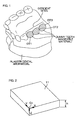
- Fig. 1 shows the dental arch model thus produced.
- the dental arch model faithfully replicates a lower dental arch on a patient's lower jaw.
- three left molar teeth are missing by way of example.
- the dental arch model may replicate a dental arch which is restored with dummy teeth DT1, DT2, DT3 of an imageable material (e.g., aluminum, apatite or the like) disposed at deficient sites.
- the dummy teeth DT1, DT2, DT3 replicate teeth to be disposed at the deficient sites in a proper arrangement as having proper sizes.
- artificial tooth roots (dental implants) for supporting the replicated teeth are required. Therefore, the implantation positions and the implantation directions of the dental implants for the replicated teeth are determined through diagnosis in a step to be described later.
- the step of positioning the dummy teeth at the deficient sites in the dental arch model is not necessarily required, but the subsequent step may be performed without positioning the dummy teeth in the dental arch model.
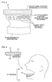
- the guide block 10 includes a processing portion 11 and an attachment portion 12.
- the processing portion 11 for example, has a rectangular plan shape and a predetermined thickness h (as measured vertically), and is composed of an imageable material (e.g., aluminum, apatite or the like).
- the processing portion 11 has, for example, a corner C0 defined by three orthogonal edges. These three edges are defined as X-, Y- and Z-axes on the processing portion 11.
- the X-, Y- and Z-axes define a processing reference coordinate system for processing the processing portion 11.
- the attachment portion 12 serves to attach the processing portion 11 to the dental arch model.
- the attachment portion 12 is composed of a non-imageable material such as an acryl resin (see Fig. 3 ).
- the processing portion 11 is positioned with respect to the dental arch model.
- the processing portion 11 is positioned generally horizontally with respect to the dental arch model as covering the deficient sites.
- an acryl resin gel is filled in a space defined between a lower surface of the processing portion 11 and the dental arch model, more specifically, in a space inside the dental arch, and properly shaped.
- the filled acryl resin is solidified with time to serve as the attachment portion 12.
- the solidified acryl resin is bonded to the lower surface of the processing portion 11 to be unified with the processing portion 11.
- the solidified acryl resin is not bonded to the dental arch model, but is removable from the dental arch model.
- the attachment portion 12 of the acryl resin thus solidified and removed from the dental arch model has an attachment surface that is conformal to the geometry of the inner side of the dental arch.
- the dummy teeth are disposed in the dental arch model in this case, the dummy teeth may be covered with the acryl resin and contained as a part of the attachment portion 12 in the guide block 10.
- the guide block 10 produced by utilizing the dental arch model is removed from the dental arch model after the acryl resin 12 is solidified.
- the removal of the guide block 10 is facilitated, for example, by preliminarily applying a releasing agent or the like onto the dental arch model. Then, the removed guide block 10 is fitted in the patient's oral cavity.
- the attachment portion 12 of the guide block 10 is conformal to the dental arch model prepared based on the patient's oral cavity and, particularly, the attachment surface of the attachment portion 12 is conformal to the geometry of the inner side of the dental arch. Therefore, the guide block 10 is perfectly fitted in the patient's oral cavity without wobble.
- the CT imaging is carried out to provide CT image data.
- a three-dimensional image of the patient's oral cavity formed based on the resulting CT image data is shown in Fig. 5 .
- the three-dimensional image shown in Fig. 5 is displayed on a display of a computer system.
- the three-dimensional image can be rotated in a desired direction. Further, a slice of a desired portion can be displayed. With this arrangement, an optimum implant implantation position and an optimum implant implantation direction (angle) are determined on the three-dimensional image through diagnosis.
- the implant implantation position and the implant implantation direction (implantation angle) determined on the three-dimensional image through the diagnosis are data specified based on a three-dimensional image display coordinate system.
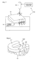
- the implant implantation positions and the implant implantation directions (implantation angles) are specified on the three-dimensional image as shown in Fig. 6 .
- Fig. 6 the three-dimensional image is displayed based on the display coordinate system (X0, Y0, Z0).
- Points a1, b1, a2, b2, a3, b3 for specifying the implant implantation positions and the implant implantation directions are represented based on the display coordinate system (X0, Y0, Z0) as follows:
- an image 11' of the processing portion 11 of the guide block 10 is also shown in the three-dimensional image of Fig. 6 .
- the corner C0 is also shown.
- the coordinates of the corner C0 are represented as follows:
- the implant implantation positions, the implant implantation directions (implantation angles), the position of the corner C0 of the processing portion 11 of the guide block 10 and the orientation of the processing portion 11 are defined as data based on the three-dimensional image display coordinate system.
- the data based on the three-dimensional image display coordinate system is transformed into data based on the processing reference coordinate system defined by the corner C0 of the processing portion 11 of the guide block 10 and the X-, Y- and Z-axes.
- the transformation is carried out, for example, in the following manner.
- the coordinates of the origin are represented by (Xc0, Yc0, Zc0) in the processing reference coordinate system on the guide block 10, the coordinates of the origin are represented by (X0c0, Y0c0, Z0c0) in the three-dimensional display coordinate system.
- the guide block 10 is set in a cutting processor 50, and fixed in position by a fixing device 51. Then, the guide block 10 is processed into a shape such as to guide the dental implants by a cutting machine 52.
- the reference coordinate system on the guide block 10 and the coordinate data of the implantation positions and the implantation directions based on the reference coordinate system (obtained through the transformation) are provided, so that the cutting machine 52 can automatically cut the guide block 10 into a shape such as to properly guide the dental implants.
- the cutting may be carried out semi-automatically, semi-manually, or manually with reference to the data, rather than automatically.
- the resulting guide block 10 serves as the implant implantation guide 100.
- Fig. 8 illustrates one example of the implant implantation guide 100.
- the implant implantation guide 100 includes a generally U-shaped portion 11' produced by processing the processing portion 11 and covering the dental arch, guide grooves G1, G2, G3 formed in the U-shaped portion 11' and an attachment portion 12.
- the guide grooves G1, G2, G3 are each dimensioned such as to guide a drill (a drill shaft or a bar), serving as a drill (drill shaft or bar) guide groove.
- the guide grooves G1, G2, G3 may each serve as a head guide groove for guiding a head of a hand piece in which the drill is chucked (a groove having a greater size than the drill guide groove).
- the attachment portion 12 of the implant implantation guide 100 to be fitted on the dental arch is composed of the acryl resin.
- the attachment portion 12 is perfectly fitted on the patient's dental arch without a gap or a play. Therefore, the implant implantation guide 100 fitted on the patient's dental arch makes it possible to properly drill implant implantation holes at the positions previously determined through the diagnosis in the patient's jawbone. That is, the drill is operated according to the implant implantation guide 100, whereby the implant implantation holes can be properly and speedily drilled in the directions at the positions previously determined through the diagnosis. Then, the dental implants are implanted at these positions.
- the processing reference coordinate system for the processing of the processing portion 11 of the guide block 10 is defined by the single corner C0 and the three edges defined as the three orthogonal lines.
- how to define the processing reference coordinate system for the processing of the processing portion 11 is not limited to the aforementioned method.
- a processing reference plane or a processing reference coordinate system may be defined based on three points preliminarily specified.
- the processing portion 11 is not necessarily required to be composed of the imageable material, but may be composed of a material such that the at least three points are imageable on the CT image.
- the processing portion 11 of the guide block 10 may be configured such that, when the processing portion 11 is imaged through the CT imaging to provide CT image data, the at least three points required for defining the processing reference plane or the processing reference coordinate system are shown on the three-dimensional image formed based on the resulting CT image data.
- the processing portion 11 may be entirely composed of the non-imageable material, and the three points required for specifying the position of the processing portion 11 may be composed of an imageable material.
- straight lines required for defining the processing reference coordinate system may be drawn with an imageable material on the processing portion 11.
- the guide block 10 prepared for the production of the implant implantation guide includes the processing portion 11 and the attachment portion 12 provided as a unitary member.
- the processing portion 11 and the attachment portion 12 of the guide block 10 may be provided as separate members.
- Fig. 9 illustrates the guide block 10 having such a structure.
- a guide base (resin base) 12 serving as the attachment portion is fitted on the dental arch model of the plaster.
- the guide base 12 is composed of, for example, an acryl resin (non-imageable material), and unitarily includes an imaging marker 114 including at least three balls 111, 112, 113.
- the three balls 111, 112, 113 each have an imageable member which defines a center thereof.
- the processing portion 11 may have the same construction as that described with reference to Fig. 2 .
- the processing portion 11 has a rectangular plan shape and a predetermined thickness h, and is composed of an imageable material (e.g., aluminum, apatite or the like).
- the guide base (resin base) 12 including the imaging marker 114, and the processing portion 11 having the processing coordinate system required for the processing are separately prepared, and only the guide base (resin base) 12 is fitted in the patient's oral cavity. Then, the CT imaging is carried out to provide the CT image data.
- the fitting of the resin base 12 shown in Fig. 9 alleviates a burden on the patient during the CT imaging.
- the imaging marker 114 including the at least three balls 111, 112, 113 is provided unitarily with the resin base 12, so that a relationship between a marker coordinate system defined by the three centers of the three balls 111, 112, 113 and the processing reference coordinate system of the processing portion 11 to be attached after the imaging can be determined by means of a three-dimensional measurement apparatus by utilizing an existing technique. Therefore, information of the implant implantation positions and the implant implantation directions determined on the CT image through the diagnosis can be transformed into the coordinate information required for the processing of the processing portion 11 of the guide block 10 via the marker coordinate system defined by the imaging marker 114. The coordinate information is used for cutting the guide block 10 through CAD/CAM.
Landscapes
- Health & Medical Sciences (AREA)
- Oral & Maxillofacial Surgery (AREA)
- Dentistry (AREA)
- Life Sciences & Earth Sciences (AREA)
- Animal Behavior & Ethology (AREA)
- General Health & Medical Sciences (AREA)
- Public Health (AREA)
- Veterinary Medicine (AREA)
- Surgery (AREA)
- Epidemiology (AREA)
- Orthopedic Medicine & Surgery (AREA)
- Nuclear Medicine, Radiotherapy & Molecular Imaging (AREA)
- Engineering & Computer Science (AREA)
- Biomedical Technology (AREA)
- Heart & Thoracic Surgery (AREA)
- Medical Informatics (AREA)
- Molecular Biology (AREA)
- Apparatus For Radiation Diagnosis (AREA)
- Dental Prosthetics (AREA)
- Dental Tools And Instruments Or Auxiliary Dental Instruments (AREA)
Abstract
A highly precise implant implantation guide has been desired for safely and precisely performing a dental implant treatment. A method of producing an implant implantation guide according to the present invention includes the steps of: (1) preparing a guide block including an attachment portion and a processing portion; (2) acquiring CT image data of a patient with the guide block being worn by the patient; (3) determining an implant implantation position and an implant implantation direction through diagnosis based on the CT image data, and transforming information of the implantation position and the implantation direction thus determined into coordinate information based on a processing reference coordinate system; and (4) cutting the guide block through CAD/CAM so as to reflect the coordinate information obtained by the transformation.
Description
- The present invention relates to a method of producing an implant implantation guide for implanting a dental implant (artificial tooth root) and, particularly, to a method of producing an implant implantation guide by utilizing a CAD/CAM system and to a guide block to be used in the producing method.
- Dental implant (artificial tooth root) treatments are widely utilized in the dental field. In order to improve the functionality (occlusal balance) and the aesthetic appearance of an artificial tooth to be fitted on a dental implant and to stably maintain the dental implant in a jawbone, it is important to properly design the implantation position and the implantation direction (implantation angle) of the dental implant through a diagnosis, and precisely implant the dental implant based on the design.
- In recent years, an attempt is made to properly determine the implantation position and the implantation direction of the dental implant through a diagnosis utilizing a three-dimensional medical image obtained by CT imaging and produce an implant implantation guide for effecting the implantation position and the implantation direction determined through the diagnosis by means of a CAD/CAM system for clinical application (see, for example, Patent Documents 1 and 2).
- However, it is difficult to produce a highly precise implant implantation guide that permits accurate positioning of the dental implant in an oral cavity based on CT imaging data alone. This is because: the CT imaging data includes data of several-hundred-micron voxels; a metal fixture attached to a tooth causes a noise called "metal artifact" in the image; a prosthetic device composed of a non-imageable material such as a resin cannot be imaged; the imaging range, the imaging depth and the size and shape of the image vary depending on CT values; and the three-dimensional image formed based on the CT imaging data has a simplified shape with reduced geometrical and dimensional accuracies.
- In other words, the implant implantation guide produced based on the CT imaging data is not as precise as that produced based on a dental arch model formed of a plaster (a dental arch model of a plaster obtained by taking an impression of a dental arch in a patient's oral cavity).
- Patent Document 1: Japanese Unexamined Patent Publication No.
2003-245289 - Patent Document 2: Japanese Unexamined Patent Publication No.
2001-170080 - It is difficult to produce the highly precise implant implantation guide based on the CT imaging data alone. Therefore, it is conceivable to substitute data obtained from the highly precise dental arch model for a corresponding data portion of the three-dimensional image formed based on the CT imaging data, and produce the implant implantation guide based on the substituted data by means of the CAD/CAM system. However, it is necessary to scan the dental arch model to obtain geometrical data of the dental arch model. Disadvantageously, the data obtained by the scanning is less precise than the original dental arch model at this stage. Further, it is difficult to eliminate an error occurring when the image is correlated with the model data for the substitution.
- In view of the foregoing, it is a principal object of the present invention to provide a method of producing a highly precise implant implantation guide for safely and precisely performing a dental implant treatment.
- According to the present invention, there is provided a method of producing an implant implantation guide for CAD/CAM, the method including the steps of: (1) preparing a guide block including an attachment portion to be fitted on a dental arch of a patient, and a processing portion having a mark of a processing reference coordinate system required for processing; (2) acquiring patient's CT image data with the guide block being fitted on the patient's dental arch; (3) transforming information of an implant implantation position and an implant implantation direction (implantation angle) determined through diagnosis on a three-dimensional image formed based on the CT image data into coordinate information based on the processing reference coordinate system on the guide block; and (4) setting the guide block in a cutting processor, and cutting the guide block into a guide shape that reflects the coordinate information based on the processing reference coordinate system.
- The attachment portion of the guide block is preferably composed of a non-imageable material, and the processing portion of the guide block is preferably composed of an imageable material.
- According to the present invention, there is provided a method of producing an implant implantation guide for CAD/CAM, the method including the steps of: (1) separately preparing a guide base including an attachment portion to be fitted on a dental arch of a patient and an imaging marker specifying at least three points, and a processing portion attachable to the guide base; (2) acquiring patient's CT image data with the guide base being fitted on the patient's dental arch; (3) providing a guide block by attaching the processing portion to the guide base for unification; (4) transforming information of an implant implantation position and an implant implantation direction (implantation angle) determined through diagnosis on a three-dimensional image formed based on the CT image data into coordinate information based on a processing reference coordinate system to be utilized for processing the processing portion via a coordinate system defined by the imaging marker; and (5) setting the guide block in a cutting processor, and cutting the guide block into a guide shape that reflects the coordinate information based on the processing reference coordinate system.
- According to the present invention, there is provided a guide block for use in the implant implantation guide producing methods described above, the guide block including an attachment portion to be fitted on a patient's dental arch, and a processing portion having a mark of a processing reference coordination system required for a cutting process.
- According to the present invention, the processing portion of the guide block is composed of an imageable material.
- According to the present invention, the guide block is first prepared. The guide block unitarily includes the processing portion to be milled (cut) into a predetermined shape in a step to be described later, and the attachment portion for attaching the processing portion to the patient's dental arch.
- The attachment portion is, for example, a dental impression of a plaster or the like directly taken from the patient's oral cavity, or formed to conform to the patient's dental arch. Therefore, when the guide block is thereafter worn by the patient, the attachment portion is perfectly fitted on the patient' s dental arch without displacement in the oral cavity.
- With the guide block being fitted in the patient's oral cavity, the patient's oral cavity is imaged through the CT imaging to provide CT image data.
- The image data thus provided is a three-dimensional image including images of patient's jawbones, a patient's dental arch, a patient's tooth deficient site and the like. The three-dimensional image also includes an image of the processing portion of the guide block fitted in the patient's oral cavity. That is, the image data includes raw image data of the patient as well as image data of the guide block.
- The implant implantation position and the implant implantation direction (implantation angle) are determined on the three-dimensional image through the diagnosis. The implantation position and the implantation direction (implantation angle) are defined, for example, in the form of a straight line on the three-dimensional image.
- The straight line representing the implantation position and the implantation direction (implantation angle) is data based on a three-dimensional image display coordinate system.
- On the other hand, the guide block is processed based on the processing reference coordinate system defined on the processing portion of the guide block in the guide block cutting step to be described later.
- The data indicating the implant implantation position and the implant implantation direction (implantation angle) determined through the diagnosis on the three-dimensional image based on the three-dimensional image display coordinate system is transformed into the data based on the processing reference coordinate system.
- Then, the guide block is set in the cutting processor, and cut into the guide shape that reflects the implant implantation position and the implant implantation direction (implantation angle) obtained through the transformation based on the processing reference coordinate system, i.e., that reflects the data of the implant implantation position and the implant implantation direction, by the CAD/CAM system.
- An implant implantation guide thus produced by the cutting process is configured such that the attachment portion to be fitted on the dental arch has a shape conformal to the dental arch model. Therefore, when the implant implantation guide is fitted in the patient's oral cavity, the implant implantation guide is perfectly fitted on the patient's dental arch without a gap. Thus, the implant implantation guide is free from wobble in the patient's oral cavity, and serves as a guide for forming a hole for implantation of the dental implant in the patient's oral cavity.
- The implant implantation guide produced by the inventive producing method is properly fitted on the dental arch in the patient's oral cavity without wobble in the patient's oral cavity.
- Since the implant implantation guide is properly and precisely fitted in the patient's oral cavity, a dental treatment can be properly performed on the patient with reference to the guide.
- In the present invention, the guide base and the processing portion of the guide block may be provided as separate members rather than as a unitary member. Where the patient who wears the guide block has a smaller mouth or suffers from a sensitive vomiting reflex, it is often difficult to fit the guide block in the patient's oral cavity for the CT imaging. In this case, it is desirable to use the guide block including the guide base and the processing portion provided as separate members. This is because the guide base is a smaller and thinner member including the attachment portion and the imaging marker, thereby alleviating a burden on the patient who wears the guide base during the CT imaging.
- By utilizing an existing technique, the imaging marker specifying the at least three points on the guide base makes it possible to transform the data based on the three-dimensional image display coordinate system into the data based on the processing reference coordinate system with the use of the coordinate system defined by the three points.
- The inventive guide block is advantageously used for a dental implant surgery on the patient.
- Particularly, where the processing portion of the guide block is composed of the imageable material, the implant implantation guide is produced by processing the guide block, and then the CT imaging is carried out with the implant implantation guide being fitted in the patient's oral cavity for confirmation. Thus, a guide surface of the implant implantation guide is clearly imaged. As required, the implant implantation guide may be modified with reference to the resulting image.
-
-
Fig. 1 is a diagram illustrating a dental arch model of a plaster to show a method of producing an implant implantation guide according to one embodiment of the present invention. -
Fig. 2 is a perspective view illustrating anexemplary processing portion 11 to show the implant implantation guide producing method according to the embodiment of the present invention. -
Fig. 3 is a diagram showing the implant implantation guide producing method according to the embodiment of the present invention, particularly, for explaining a method of producing aguide block 10 from the dental arch model. -
Fig. 4 is a diagram showing the implant implantation guide producing method according to the embodiment of the present invention, particularly, for explaining the step of acquiring CT image data. -
Fig. 5 is a diagram illustrating an exemplary three-dimensional image based on the resulting CT image data to show the implant implantation guide producing method according to the embodiment of the present invention. -
Fig. 6 is a diagram showing the implant implantation guide producing method according to the embodiment of the present invention, particularly, for explaining how to carry out a coordinate transformation. -
Fig. 7 is a diagram showing the implant implantation guide producing method according to the embodiment of the present invention, particularly, for explaining the cutting of theguide block 10. -
Fig. 8 is a perspective view illustrating an exemplaryimplant implantation guide 100. -
Fig. 9 is a diagram for explaining anotherexemplary guide block 10 to be used for the implant implantation guide producing method according to the embodiment of the present invention. -
- 10: GUIDE BLOCK
- 11: PROCESSING PORTION
- 12: ATTACHMENT PORTION
- 50: CUTTING PROCESSOR
- 52: CUTTING MACHINE
- 100: IMPLANT IMPLANTATION GUIDE
- Specific embodiments of the present invention will hereinafter be described with reference to the drawings.
-
Figs. 1 to 7 show a method of producing an implant implantation guide according to one embodiment of the present invention. - First, a dental arch model of a patient who is to be subjected to an implant treatment is produced. The production of the dental arch model is achieved, for example, by taking a patient's dental impression with a plaster by a conventionally known method.
-
Fig. 1 shows the dental arch model thus produced. The dental arch model faithfully replicates a lower dental arch on a patient's lower jaw. In the dental arch model, three left molar teeth are missing by way of example. - The dental arch model may replicate a dental arch which is restored with dummy teeth DT1, DT2, DT3 of an imageable material (e.g., aluminum, apatite or the like) disposed at deficient sites. The dummy teeth DT1, DT2, DT3 replicate teeth to be disposed at the deficient sites in a proper arrangement as having proper sizes. In order to maintain the replicated teeth in this state, artificial tooth roots (dental implants) for supporting the replicated teeth are required. Therefore, the implantation positions and the implantation directions of the dental implants for the replicated teeth are determined through diagnosis in a step to be described later.
- The step of positioning the dummy teeth at the deficient sites in the dental arch model is not necessarily required, but the subsequent step may be performed without positioning the dummy teeth in the dental arch model.
- Next, a
guide block 10 to be fitted on the dental arch model is produced. Theguide block 10 includes aprocessing portion 11 and anattachment portion 12. As shown inFig. 2 , theprocessing portion 11, for example, has a rectangular plan shape and a predetermined thickness h (as measured vertically), and is composed of an imageable material (e.g., aluminum, apatite or the like). - The
processing portion 11 has, for example, a corner C0 defined by three orthogonal edges. These three edges are defined as X-, Y- and Z-axes on theprocessing portion 11. The X-, Y- and Z-axes define a processing reference coordinate system for processing theprocessing portion 11. - The
attachment portion 12 serves to attach theprocessing portion 11 to the dental arch model. Theattachment portion 12 is composed of a non-imageable material such as an acryl resin (seeFig. 3 ). - The
processing portion 11 is positioned with respect to the dental arch model. For example, theprocessing portion 11 is positioned generally horizontally with respect to the dental arch model as covering the deficient sites. In order to fix the position of theprocessing portion 11 with respect to the dental arch model, an acryl resin gel is filled in a space defined between a lower surface of theprocessing portion 11 and the dental arch model, more specifically, in a space inside the dental arch, and properly shaped. - The filled acryl resin is solidified with time to serve as the
attachment portion 12. The solidified acryl resin is bonded to the lower surface of theprocessing portion 11 to be unified with theprocessing portion 11. On the other hand, the solidified acryl resin is not bonded to the dental arch model, but is removable from the dental arch model. Theattachment portion 12 of the acryl resin thus solidified and removed from the dental arch model has an attachment surface that is conformal to the geometry of the inner side of the dental arch. - Where the dummy teeth are disposed in the dental arch model in this case, the dummy teeth may be covered with the acryl resin and contained as a part of the
attachment portion 12 in theguide block 10. - Referring to
Fig. 4 , theguide block 10 produced by utilizing the dental arch model is removed from the dental arch model after theacryl resin 12 is solidified. The removal of theguide block 10 is facilitated, for example, by preliminarily applying a releasing agent or the like onto the dental arch model. Then, the removedguide block 10 is fitted in the patient's oral cavity. - The
attachment portion 12 of theguide block 10 is conformal to the dental arch model prepared based on the patient's oral cavity and, particularly, the attachment surface of theattachment portion 12 is conformal to the geometry of the inner side of the dental arch. Therefore, theguide block 10 is perfectly fitted in the patient's oral cavity without wobble. - With the
guide block 10 being fitted in the patient's oral cavity, the CT imaging is carried out to provide CT image data. A three-dimensional image of the patient's oral cavity formed based on the resulting CT image data is shown inFig. 5 . - The three-dimensional image shown in
Fig. 5 is displayed on a display of a computer system. The three-dimensional image can be rotated in a desired direction. Further, a slice of a desired portion can be displayed. With this arrangement, an optimum implant implantation position and an optimum implant implantation direction (angle) are determined on the three-dimensional image through diagnosis. - Meanwhile, the implant implantation position and the implant implantation direction (implantation angle) determined on the three-dimensional image through the diagnosis are data specified based on a three-dimensional image display coordinate system.
- For example, it is herein assumed that the implant implantation positions and the implant implantation directions (implantation angles) are specified on the three-dimensional image as shown in
Fig. 6 . - In
Fig. 6 , the three-dimensional image is displayed based on the display coordinate system (X0, Y0, Z0). Points a1, b1, a2, b2, a3, b3 for specifying the implant implantation positions and the implant implantation directions are represented based on the display coordinate system (X0, Y0, Z0) as follows: - a1=(x0a1, y0a1, z0a1)
- b1=(x0b1, y0b1, z0b1)
- a2=(x0a2, y0a2, z0a2)
- b2=(x0b2, y0b2, z0b2)
- a3=(x0a3, y0a3, z0a3)
- b3=(x0b3, y0b3, z0b3)
- A line segment extending between the points a1 and b1 is represented as follows:
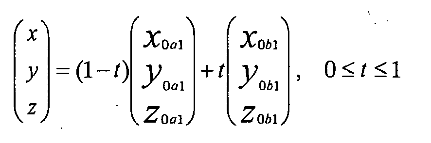
- On the other hand, an image 11' of the
processing portion 11 of theguide block 10 is also shown in the three-dimensional image ofFig. 6 . The corner C0 is also shown. In the three-dimensional image ofFig. 6 , the coordinates of the corner C0 are represented as follows: - C0=(x0c0, y0c0, z0c0)
- That is, the coordinates (X, Y, Z) are represented as follows:
- (X, Y, Z)=(θCOX0+C0, θCOY0+C0, θCOZ0+C0)
- Thus, in the three-dimensional image, the implant implantation positions, the implant implantation directions (implantation angles), the position of the corner C0 of the
processing portion 11 of theguide block 10 and the orientation of the processing portion 11 (directions of the X-, Y- and Z-axes) are defined as data based on the three-dimensional image display coordinate system. - Next, the data based on the three-dimensional image display coordinate system is transformed into data based on the processing reference coordinate system defined by the corner C0 of the
processing portion 11 of theguide block 10 and the X-, Y- and Z-axes. - The transformation is carried out, for example, in the following manner.
- Provided that the coordinates of the origin are represented by (Xc0, Yc0, Zc0) in the processing reference coordinate system on the
guide block 10, the coordinates of the origin are represented by (X0c0, Y0c0, Z0c0) in the three-dimensional display coordinate system. - On the other hand, provided that coordinates associated with the implant implantation positions and the implant implantation directions (implantation angles) determined on the three-dimensional image through the diagnosis are represented by (X0a1, Y0a1, Z0a1) on the three-dimensional image, the coordinates (based on the three dimensional display coordinate system) are transformed into coordinates based on the processing reference coordinate system in the following manner:
- (X0a1, Y0a1, Z0a1)×(Xc0, Yc0, Zc0)÷(X0c0, Y0c0, Z0c0) =(Xa1, Ya1, Za1)
- Next, as shown in
Fig. 7 , theguide block 10 is set in a cuttingprocessor 50, and fixed in position by a fixingdevice 51. Then, theguide block 10 is processed into a shape such as to guide the dental implants by a cuttingmachine 52. - In the cutting process, the reference coordinate system on the
guide block 10 and the coordinate data of the implantation positions and the implantation directions based on the reference coordinate system (obtained through the transformation) are provided, so that the cuttingmachine 52 can automatically cut theguide block 10 into a shape such as to properly guide the dental implants. The cutting may be carried out semi-automatically, semi-manually, or manually with reference to the data, rather than automatically. - The resulting
guide block 10 serves as theimplant implantation guide 100. -
Fig. 8 illustrates one example of theimplant implantation guide 100. Theimplant implantation guide 100 includes a generally U-shaped portion 11' produced by processing theprocessing portion 11 and covering the dental arch, guide grooves G1, G2, G3 formed in the U-shaped portion 11' and anattachment portion 12. - The guide grooves G1, G2, G3 are each dimensioned such as to guide a drill (a drill shaft or a bar), serving as a drill (drill shaft or bar) guide groove. Alternatively, the guide grooves G1, G2, G3 may each serve as a head guide groove for guiding a head of a hand piece in which the drill is chucked (a groove having a greater size than the drill guide groove).
- The
attachment portion 12 of theimplant implantation guide 100 to be fitted on the dental arch is composed of the acryl resin. Theattachment portion 12 is perfectly fitted on the patient's dental arch without a gap or a play. Therefore, theimplant implantation guide 100 fitted on the patient's dental arch makes it possible to properly drill implant implantation holes at the positions previously determined through the diagnosis in the patient's jawbone. That is, the drill is operated according to theimplant implantation guide 100, whereby the implant implantation holes can be properly and speedily drilled in the directions at the positions previously determined through the diagnosis. Then, the dental implants are implanted at these positions. - In the aforementioned embodiment, the processing reference coordinate system for the processing of the
processing portion 11 of theguide block 10 is defined by the single corner C0 and the three edges defined as the three orthogonal lines. However, how to define the processing reference coordinate system for the processing of theprocessing portion 11 is not limited to the aforementioned method. - For example, as disclosed in Japanese Patent Application No.
2004-334936 - In this case, the
processing portion 11 is not necessarily required to be composed of the imageable material, but may be composed of a material such that the at least three points are imageable on the CT image. - More specifically, the
processing portion 11 of theguide block 10 may be configured such that, when theprocessing portion 11 is imaged through the CT imaging to provide CT image data, the at least three points required for defining the processing reference plane or the processing reference coordinate system are shown on the three-dimensional image formed based on the resulting CT image data. For example, theprocessing portion 11 may be entirely composed of the non-imageable material, and the three points required for specifying the position of theprocessing portion 11 may be composed of an imageable material. Alternatively, straight lines required for defining the processing reference coordinate system may be drawn with an imageable material on theprocessing portion 11. - In the embodiment described above, the
guide block 10 prepared for the production of the implant implantation guide includes theprocessing portion 11 and theattachment portion 12 provided as a unitary member. However, at the initial stage, theprocessing portion 11 and theattachment portion 12 of theguide block 10 may be provided as separate members. -
Fig. 9 illustrates theguide block 10 having such a structure. - Referring to
Fig. 9 , a guide base (resin base) 12 serving as the attachment portion is fitted on the dental arch model of the plaster. Theguide base 12 is composed of, for example, an acryl resin (non-imageable material), and unitarily includes animaging marker 114 including at least threeballs balls - The
processing portion 11 may have the same construction as that described with reference toFig. 2 . For example, theprocessing portion 11 has a rectangular plan shape and a predetermined thickness h, and is composed of an imageable material (e.g., aluminum, apatite or the like). - The guide base (resin base) 12 including the
imaging marker 114, and theprocessing portion 11 having the processing coordinate system required for the processing are separately prepared, and only the guide base (resin base) 12 is fitted in the patient's oral cavity. Then, the CT imaging is carried out to provide the CT image data. - If it is difficult to fit the
guide block 10 shown inFig. 3 in the patient's oral cavity because the patient has a smaller mouth or suffers from a sensitive vomiting reflex, the fitting of theresin base 12 shown inFig. 9 alleviates a burden on the patient during the CT imaging. - In this case, the
imaging marker 114 including the at least threeballs resin base 12, so that a relationship between a marker coordinate system defined by the three centers of the threeballs processing portion 11 to be attached after the imaging can be determined by means of a three-dimensional measurement apparatus by utilizing an existing technique. Therefore, information of the implant implantation positions and the implant implantation directions determined on the CT image through the diagnosis can be transformed into the coordinate information required for the processing of theprocessing portion 11 of theguide block 10 via the marker coordinate system defined by theimaging marker 114. The coordinate information is used for cutting theguide block 10 through CAD/CAM. - The present invention is not limited to the embodiments described above, but various modifications may be made within the scope of the present invention defined by the following claims.
Claims (5)
- A method of producing an implant implantation guide for CAD/CAM, comprising the steps of:(1) preparing a guide block including an attachment portion to be fitted on a dental arch of a patient, and a processing portion having a mark of a processing reference coordinate system required for processing;(2) acquiring patient's CT image data with the guide block being fitted on the patient' s dental arch;(3) transforming information of an implant implantation position and an implant implantation direction (implantation angle) determined through diagnosis on a three-dimensional image formed based on the CT image data into coordinate information based on the processing reference coordinate system on the guide block; and(4) setting the guide block in a cutting processor, and cutting the guide block into a guide shape that reflects the coordinate information based on the processing reference coordinate system.
- An implant implantation guide producing method for CAD/CAM as set forth in claim 1,
wherein the attachment portion of the guide block is composed of a non-imageable material,
wherein the processing portion of the guide block is composed of an imageable material. - A method of producing an implant implantation guide for CAD/CAM, comprising the steps of:(1) separately preparing a guide base including an attachment portion to be fitted on a dental arch of a patient and an imaging marker specifying at least three points, and a processing portion attachable to the guide base;(2) acquiring patient's CT image data with the guide base being fitted on the patient's dental arch;(3) providing a guide block by attaching the processing portion to the guide base for unification;(4) transforming information of an implant implantation position and an implant implantation direction (implantation angle) determined through diagnosis on a three-dimensional image formed based on the CT image data into coordinate information based on a processing reference coordinate system to be utilized for processing the processing portion via a coordinate system defined by the imaging marker; and(5) setting the guide block in a cutting processor, and cutting the guide block into a guide shape that reflects the coordinate information based on the processing reference coordinate system.
- A guide block for use in an implant implantation guide producing method as recited in claim 1 or 3, the guide block comprising:an attachment portion to be fitted on a patient's dental arch; anda processing portion having a mark of a processing reference coordination system required for a cutting process.
- A guide block as set forth in claim 4,
wherein the processing portion is composed of an imageable material.
Applications Claiming Priority (2)
| Application Number | Priority Date | Filing Date | Title |
|---|---|---|---|
| JP2006259129A JP2008073440A (en) | 2006-09-25 | 2006-09-25 | Implant planting guide manufacturing method and guide block |
| PCT/JP2007/065909 WO2008038471A1 (en) | 2006-09-25 | 2007-08-15 | Implantation guide making method and guide block |
Publications (2)
| Publication Number | Publication Date |
|---|---|
| EP2072018A1 true EP2072018A1 (en) | 2009-06-24 |
| EP2072018A4 EP2072018A4 (en) | 2011-04-27 |
Family
ID=39229911
Family Applications (1)
| Application Number | Title | Priority Date | Filing Date |
|---|---|---|---|
| EP07792543A Withdrawn EP2072018A4 (en) | 2006-09-25 | 2007-08-15 | METHOD FOR MANUFACTURING IMPLANTATION GUIDE AND GUIDE BLOCK |
Country Status (7)
| Country | Link |
|---|---|
| US (1) | US20090274990A1 (en) |
| EP (1) | EP2072018A4 (en) |
| JP (1) | JP2008073440A (en) |
| KR (1) | KR20090069166A (en) |
| CN (1) | CN101528153A (en) |
| CA (1) | CA2664351A1 (en) |
| WO (1) | WO2008038471A1 (en) |
Cited By (12)
| Publication number | Priority date | Publication date | Assignee | Title |
|---|---|---|---|---|
| WO2010097405A1 (en) * | 2009-02-27 | 2010-09-02 | Marcus Abboud | Drilling jig and method for the production thereof |
| WO2010143090A1 (en) * | 2009-06-12 | 2010-12-16 | Jean Capsal | Method for making a guide for drilling a patient's bone |
| WO2012004282A1 (en) * | 2010-07-06 | 2012-01-12 | Sirona Dental Systems Gmbh | Method and clamping fixture for producing a dental drilling template |
| EP2425797A1 (en) * | 2010-09-02 | 2012-03-07 | Marcus Abboud | Implant assistance assembly for implanting a jaw implant |
| WO2012110850A3 (en) * | 2010-11-17 | 2012-12-27 | AHN, Kyung, Sook | Tooth preparation guide device and method of preparing tooth for dental prosthesis |
| US8651860B2 (en) | 2010-11-17 | 2014-02-18 | Kyung Sook Ahn | Tooth preparation guide device and method of preparing tooth for dental prosthesis |
| EP2957251A1 (en) | 2014-06-19 | 2015-12-23 | R+K CAD CAM Technologie GmbH & Co. KG | Device for use in a method for the production of a dental implant structure |
| EP2705797A4 (en) * | 2011-05-04 | 2016-01-13 | Tae-Kyoung Yi | Marker for image information registration |
| CN109077822A (en) * | 2018-06-22 | 2018-12-25 | 雅客智慧(北京)科技有限公司 | A kind of the dentistry plantation mobile phone calibration system and method for view-based access control model measurement |
| EP3456284A1 (en) * | 2009-02-02 | 2019-03-20 | Viax Dental Technologies, Llc | Method for producing a dentist tool |
| USRE48318E1 (en) | 2010-11-17 | 2020-11-24 | Digiprep Dental, Inc. | Tooth preparation guide device and method of preparing tooth for dental prosthesis |
| US12514686B2 (en) | 2019-03-11 | 2026-01-06 | Zebris Medical Gmbh | Dental splint and method for producing same |
Families Citing this family (43)
| Publication number | Priority date | Publication date | Assignee | Title |
|---|---|---|---|---|
| EP1506745A1 (en) * | 2003-08-15 | 2005-02-16 | Jeanette Mörmann | Blank and method for making a dental restoration |
| ITBS20070040A1 (en) * | 2007-03-26 | 2008-09-27 | Studio Dentistico Dr Jacotti M | METHOD OF REALIZING A GUIDE MASK FOR DENTAL IMPLANTOLOGY, A GUIDE MASK GETTING OBTAINED AND A REFERENCE DEVICE FOR THE EXECUTION OF THE METHOD |
| JP5250251B2 (en) * | 2007-12-17 | 2013-07-31 | イマグノーシス株式会社 | Medical imaging marker and its utilization program |
| WO2010022479A2 (en) * | 2008-08-29 | 2010-03-04 | De Clerck Rene | Method and transfer element for manufacturing a superstructure and a corresponding template |
| CN102215779A (en) * | 2008-11-18 | 2011-10-12 | Ibur有限责任公司 | Dental device and method for linking physical and digital data for diagnostic, treatment planning, patient education, communication, manufacturing, and data transfer purposes |
| JP5322621B2 (en) * | 2008-12-19 | 2013-10-23 | 京セラメディカル株式会社 | Production apparatus for oral model for stent production and production system for oral model for stent production |
| US8640338B2 (en) | 2009-02-02 | 2014-02-04 | Viax Dental Technologies, LLC | Method of preparation for restoring tooth structure |
| US20100192375A1 (en) | 2009-02-02 | 2010-08-05 | Remedent Nv | Method for producing a dentist tool |
| BR112012015519A2 (en) * | 2009-12-22 | 2020-08-25 | Lambert J. Stumpel | method for preparing a surgical guide and surgical guide system for a dental implant procedure |
| KR101096746B1 (en) * | 2009-12-24 | 2011-12-21 | 주식회사 사이버메드 | How to make a surgical guide |
| KR101118716B1 (en) * | 2010-02-08 | 2012-03-12 | 정제교 | Machining apparatus based on synchronized coordinate and Machining method thereof |
| AU2010361200C1 (en) * | 2010-09-21 | 2015-04-16 | Implantdent Co., Ltd. | "Gauge body and method for preparing surgical guide" |
| IT1402727B1 (en) * | 2010-10-29 | 2013-09-18 | Physioplant S R L | METHOD FOR THE PREPARATION OF A SURGICAL MASK FOR THE INSTALLATION OF A DENTAL IMPLANT |
| TWI448276B (en) * | 2010-11-26 | 2014-08-11 | Po Kun Cheng | Dental positioning stent and manufacturing method for the same |
| US8954181B2 (en) * | 2010-12-07 | 2015-02-10 | Sirona Dental Systems Gmbh | Systems, methods, apparatuses, and computer-readable storage media for designing and manufacturing custom dental preparation guides |
| US20120214121A1 (en) * | 2011-01-26 | 2012-08-23 | Greenberg Surgical Technologies, Llc | Orthodontic Treatment Integrating Optical Scanning and CT Scan Data |
| KR101219150B1 (en) * | 2011-02-10 | 2013-01-08 | 주식회사 메가젠임플란트 | Method of manufacturing surgical guide for dental implant |
| DE102011013191B4 (en) * | 2011-03-05 | 2014-04-03 | Karsten Baumann | Method for creating a surgical template for an implant surgery in a jaw |
| KR101256655B1 (en) * | 2011-05-19 | 2013-04-19 | 연세대학교 산학협력단 | Tooth model for hands-on education of implant, regenerative surgeries and basic surgical techniques |
| RU2745030C2 (en) | 2011-05-26 | 2021-03-18 | Вайэкс Дентал Текнолоджиз, Ллк | Dental instrument and guide units |
| WO2013008963A1 (en) * | 2011-07-12 | 2013-01-17 | Yi Tae Kyoung | Image-based coordinate synchronizing plate |
| TWI504383B (en) * | 2012-11-27 | 2015-10-21 | Nat Univ Chung Cheng | Computer - aided positioning guidance system for dental implants |
| DE102014102206B4 (en) * | 2013-03-08 | 2016-05-12 | Jörg Bressem | Method for producing a dental component and dental component |
| EP2964128A1 (en) * | 2013-03-08 | 2016-01-13 | Trophy | Partial surgical guide |
| US10639129B2 (en) | 2013-03-14 | 2020-05-05 | National Dentex, Llc | Bone foundation guide system and method |
| US10307226B2 (en) | 2013-03-14 | 2019-06-04 | National Dentex, Llc | Bone foundation guide and method of use |
| US10405945B2 (en) | 2013-03-14 | 2019-09-10 | National Dentex, Llc | Bone foundation guide and method of use |
| US10398530B2 (en) | 2013-03-14 | 2019-09-03 | National Dentex, Llc | Bone foundation guide system and method |
| US10278789B2 (en) | 2013-03-14 | 2019-05-07 | National Dentex, Llc | Bone foundation guide system and method |
| KR101481305B1 (en) * | 2013-08-12 | 2015-01-14 | 연세대학교 원주산학협력단 | A method of manufacturing surgical guide for implant surgery |
| CN104699865B (en) * | 2013-12-09 | 2018-05-22 | 南京智周信息科技有限公司 | A kind of digitalized oral cavity fixes the method and device repaired |
| US9283055B2 (en) | 2014-04-01 | 2016-03-15 | FPJ Enterprises, LLC | Method for establishing drill trajectory for dental implants |
| CN104000665B (en) * | 2014-05-27 | 2017-09-12 | 中国人民解放军第四军医大学 | A kind of 3 D positioning equipment |
| CN104323865B (en) * | 2014-10-13 | 2018-01-02 | 首都医科大学附属北京口腔医院 | Correction micro screw implantation guide plate and preparation method thereof |
| JP6063523B1 (en) * | 2015-06-29 | 2017-01-18 | 株式会社クラフトデンタル | Surgical guide manufacturing method |
| EP3364908A1 (en) | 2015-10-23 | 2018-08-29 | Daniel R. Llop | Bone foundation guide system and method |
| WO2017155823A1 (en) | 2016-03-05 | 2017-09-14 | National Dentex, Llc | Bone foundation guide system and method |
| DE102016004641A1 (en) * | 2016-04-20 | 2017-10-26 | Axel Scheffer | Method and system for detecting the alignment of at least one drill sleeve in a drilling template produced for the correct position implantation of dental implants |
| US11007035B2 (en) | 2017-03-16 | 2021-05-18 | Viax Dental Technologies Llc | System for preparing teeth for the placement of veneers |
| DE102017115750A1 (en) * | 2017-07-13 | 2019-01-17 | Karl Leibinger Medizintechnik Gmbh & Co. Kg | Dysgnathic bone positioning device with separation tool guide device / section |
| CN107951538B (en) * | 2017-12-15 | 2020-11-17 | 中南大学湘雅医院 | Manufacturing method of 3D printing fibula reconstruction jaw bone surgical tool combining bone resection and titanium plate positioning |
| US12138131B2 (en) | 2019-01-04 | 2024-11-12 | Viax Dental Technologies Llc | Tooth preparation system with lateral prongs for limiting three-dimensional movement |
| CN110353723A (en) * | 2019-07-30 | 2019-10-22 | 深圳市倍康美医疗电子商务有限公司 | Combined type radiates the production method of guide plate and combined type radiates guide plate |
Family Cites Families (6)
| Publication number | Priority date | Publication date | Assignee | Title |
|---|---|---|---|---|
| FR2705027B1 (en) * | 1993-05-11 | 1995-07-28 | Univ Joseph Fourier | Gutter to prepare the installation of a dental implant. |
| US6296483B1 (en) * | 1997-03-07 | 2001-10-02 | Universite Joseph Fourier | System for preparing the placing of a dental implant |
| DE19902273A1 (en) * | 1999-01-21 | 2000-08-03 | Dieter Edinger | Positioning appliance for dental implant in jawbone involves reference frame, fixture element. detachable element, and screw sleeve connection |
| DE19952962B4 (en) | 1999-11-03 | 2004-07-01 | Sirona Dental Systems Gmbh | Method for producing a drilling aid for a dental implant |
| JP2003245289A (en) * | 2002-02-22 | 2003-09-02 | Univ Nihon | Dental implant treatment support device |
| JP2004334936A (en) | 2003-05-01 | 2004-11-25 | Origin Electric Co Ltd | Optical disk manufacturing equipment |
-
2006
- 2006-09-25 JP JP2006259129A patent/JP2008073440A/en active Pending
-
2007
- 2007-08-15 KR KR1020097005636A patent/KR20090069166A/en not_active Ceased
- 2007-08-15 EP EP07792543A patent/EP2072018A4/en not_active Withdrawn
- 2007-08-15 WO PCT/JP2007/065909 patent/WO2008038471A1/en not_active Ceased
- 2007-08-15 CA CA002664351A patent/CA2664351A1/en not_active Abandoned
- 2007-08-15 US US12/311,245 patent/US20090274990A1/en not_active Abandoned
- 2007-08-15 CN CNA2007800347782A patent/CN101528153A/en active Pending
Cited By (20)
| Publication number | Priority date | Publication date | Assignee | Title |
|---|---|---|---|---|
| EP3456284A1 (en) * | 2009-02-02 | 2019-03-20 | Viax Dental Technologies, Llc | Method for producing a dentist tool |
| WO2010097405A1 (en) * | 2009-02-27 | 2010-09-02 | Marcus Abboud | Drilling jig and method for the production thereof |
| US11510753B2 (en) | 2009-02-27 | 2022-11-29 | Marcus Abboud | Drilling jig and method for the production thereof |
| US9925018B2 (en) | 2009-02-27 | 2018-03-27 | Marcus Abboud | Method for the production of a drilling jig |
| WO2010143090A1 (en) * | 2009-06-12 | 2010-12-16 | Jean Capsal | Method for making a guide for drilling a patient's bone |
| FR2946522A1 (en) * | 2009-06-12 | 2010-12-17 | Jean Capsal | METHOD FOR THE POSITIONING OF DENTAL PROSTHESES USED BY BONE IMPLANTS AND FOR THE PRODUCTION OF A GUIDE FOR DRILLING THE BONE OF A PATIENT |
| US9378308B2 (en) | 2010-07-06 | 2016-06-28 | Sirona Dental Systems Gmbh | Method and clamping fixture for the producing of a dental drilling template |
| WO2012004282A1 (en) * | 2010-07-06 | 2012-01-12 | Sirona Dental Systems Gmbh | Method and clamping fixture for producing a dental drilling template |
| DE102010031018A1 (en) * | 2010-07-06 | 2012-01-12 | Sirona Dental Systems Gmbh | Method and clamping device for producing a dental surgical template |
| EP2425797A1 (en) * | 2010-09-02 | 2012-03-07 | Marcus Abboud | Implant assistance assembly for implanting a jaw implant |
| USRE46813E1 (en) | 2010-11-17 | 2018-05-01 | Winverts, Inc. | Tooth preparation guide device and method of preparing tooth for dental prosthesis |
| US8651860B2 (en) | 2010-11-17 | 2014-02-18 | Kyung Sook Ahn | Tooth preparation guide device and method of preparing tooth for dental prosthesis |
| USRE48318E1 (en) | 2010-11-17 | 2020-11-24 | Digiprep Dental, Inc. | Tooth preparation guide device and method of preparing tooth for dental prosthesis |
| WO2012110850A3 (en) * | 2010-11-17 | 2012-12-27 | AHN, Kyung, Sook | Tooth preparation guide device and method of preparing tooth for dental prosthesis |
| USRE49487E1 (en) | 2010-11-17 | 2023-04-11 | Winverts, Inc. | Tooth preparation guide device and method of preparing tooth for dental prosthesis |
| EP2705797A4 (en) * | 2011-05-04 | 2016-01-13 | Tae-Kyoung Yi | Marker for image information registration |
| EP2957251A1 (en) | 2014-06-19 | 2015-12-23 | R+K CAD CAM Technologie GmbH & Co. KG | Device for use in a method for the production of a dental implant structure |
| EP3760158A1 (en) | 2014-06-19 | 2021-01-06 | R+K CAD CAM Technologie GmbH & Co. KG | Device for use in a method for the production of a dental implant structure |
| CN109077822A (en) * | 2018-06-22 | 2018-12-25 | 雅客智慧(北京)科技有限公司 | A kind of the dentistry plantation mobile phone calibration system and method for view-based access control model measurement |
| US12514686B2 (en) | 2019-03-11 | 2026-01-06 | Zebris Medical Gmbh | Dental splint and method for producing same |
Also Published As
| Publication number | Publication date |
|---|---|
| WO2008038471A1 (en) | 2008-04-03 |
| US20090274990A1 (en) | 2009-11-05 |
| CA2664351A1 (en) | 2008-04-03 |
| CN101528153A (en) | 2009-09-09 |
| KR20090069166A (en) | 2009-06-29 |
| JP2008073440A (en) | 2008-04-03 |
| EP2072018A4 (en) | 2011-04-27 |
Similar Documents
| Publication | Publication Date | Title |
|---|---|---|
| EP2072018A1 (en) | Implantation guide making method and guide block | |
| US12016741B2 (en) | System for preparing teeth for the placement of veneers | |
| KR101473192B1 (en) | method of manufacturing guide stent for dental implant | |
| US8529255B2 (en) | Dental prosthesis system | |
| US9519749B2 (en) | Surgical guide and method | |
| JP2001523509A (en) | Surgical template assembly and method for implanting a perforated artificial dental root | |
| RU2019111128A (en) | POSITIONING BY FORCE CLOSING OR GEOMETRIC CLOSING OF SURGICAL PATTERNS FOR GUIDED DENTAL IMPLANTOLOGY | |
| US20120028213A1 (en) | Method and apparatus for bending a guide post used in forming a template for locating a dental inplant hole | |
| JP2008528220A (en) | Dental prosthesis manufacturing method and apparatus used therefor | |
| JP2010505598A (en) | Surgical guide for dental implants and method of use thereof | |
| KR20080034472A (en) | 3D image registration of 3D objects | |
| JP2019528938A5 (en) | ||
| CA2817236A1 (en) | Methods for producing a laboratory analogue for dental implants | |
| JP3625278B2 (en) | Implant planting jig and manufacturing method thereof | |
| KR101481305B1 (en) | A method of manufacturing surgical guide for implant surgery | |
| EP3375401B1 (en) | Template and method for planning the surgery of dental implants and/or guided placement of a prosthesis on implants | |
| EP1609433A1 (en) | Device for determining dynamicallythe orientation of surgical stents on reference templates for preparing implantation sites to be provided in dental, orthopedic and similar surgery | |
| KR101452718B1 (en) | bite tray for image matching | |
| KR20190031711A (en) | Edentulous jaw surgical guide and method for manufacturing the same | |
| JP2013102929A (en) | System for embedding artificial tooth root |
Legal Events
| Date | Code | Title | Description |
|---|---|---|---|
| PUAI | Public reference made under article 153(3) epc to a published international application that has entered the european phase |
Free format text: ORIGINAL CODE: 0009012 |
|
| 17P | Request for examination filed |
Effective date: 20090418 |
|
| AK | Designated contracting states |
Kind code of ref document: A1 Designated state(s): AT BE BG CH CY CZ DE DK EE ES FI FR GB GR HU IE IS IT LI LT LU LV MC MT NL PL PT RO SE SI SK TR |
|
| AX | Request for extension of the european patent |
Extension state: AL BA HR MK RS |
|
| A4 | Supplementary search report drawn up and despatched |
Effective date: 20110324 |
|
| DAX | Request for extension of the european patent (deleted) | ||
| STAA | Information on the status of an ep patent application or granted ep patent |
Free format text: STATUS: THE APPLICATION IS DEEMED TO BE WITHDRAWN |
|
| 18D | Application deemed to be withdrawn |
Effective date: 20140301 |