EP2071713A2 - Centrifugal driving electricity generation system for energy conservation - Google Patents
Centrifugal driving electricity generation system for energy conservation Download PDFInfo
- Publication number
- EP2071713A2 EP2071713A2 EP20080168133 EP08168133A EP2071713A2 EP 2071713 A2 EP2071713 A2 EP 2071713A2 EP 20080168133 EP20080168133 EP 20080168133 EP 08168133 A EP08168133 A EP 08168133A EP 2071713 A2 EP2071713 A2 EP 2071713A2
- Authority
- EP
- European Patent Office
- Prior art keywords
- centrifugal
- gearing wheel
- kinetic energy
- driving
- generation system
- Prior art date
- Legal status (The legal status is an assumption and is not a legal conclusion. Google has not performed a legal analysis and makes no representation as to the accuracy of the status listed.)
- Withdrawn
Links
Images


Classifications
-
- H—ELECTRICITY
- H02—GENERATION; CONVERSION OR DISTRIBUTION OF ELECTRIC POWER
- H02K—DYNAMO-ELECTRIC MACHINES
- H02K53/00—Alleged dynamo-electric perpetua mobilia
Definitions
- This invention relates to a centrifugal driving electricity generation system provided for energy conservation and particularly to a centrifugal driving electricity generation system that uses a kinetic energy driving system consuming less energy to drive an electricity generation system consuming more energy to generate electricity for achievement of energy conservation.
- Electric energy is quite essential in modem life and also the mother of industrial economy; in people's life, most devices and products are driven by the electric energy.
- energy is generally converted from energy; for example, thermal power converts thermal energy into the electric energy, and hydraulic power and wind power converts the energy into the electric energy. During the energy conversion, some energy is still converted into thermal energy and thus consumed, while some energy is rubbed and thus consumed.
- electromagnetic induction is generally used to generate induction current from an induction system, which is led and supplied to a device or a storage device for a future use.
- a rotor in the power generator In order to drive the power generator to generate the induction current, a rotor in the power generator must be driven to rotate and then induce a nearby magnetic-force component; in order to drive the rotor to rotate, an activating system is generally used.
- the activating system is an engine powered with diesel or gasoline as a fuel.
- diesel or gasoline that is consumed to drive the engine to run, the rotor is driven to rotate and thus the kinetic energy is converted into electric energy for output.
- a conventional power generation device continuously converts various forms of energy in various manners of conversion into the electric energy, so the power generation device requires various forms of external energy to operate.
- a thermal power generator and a small power generator must continuously combust the fuel that pollutes the environment, and a hydraulic power generator and a wind power generator are limited to the conditions of weather and geography of great universe, which is thus not easily implemented.
- a power generation system powered with higher energy is driven at a centrifugal terminal to generate power.
- the system according to this invention comprises a power generation system that may be driven to generate electricity; a kinetic energy driving system that may be powered with inputted electric energy or the fuel and that drives an impelled rotary system through the centrifugal terminal to rotate, which makes outputted kinetic energy increase multiple times in the principle of contrast between the centrifugal and the application of force; a impelled rotary system the rotation center of which links with the power generation system, in which the centrifugal terminal is impelled by the kinetic energy driving system to drive the power generation system for power generation; a gearing wheel system grouped with several larger and smaller gearing wheels that are equipped on an axis between the power generation system and the impelled rotary system to transmit the kinetic energy and vary the constant rotation speed for linking with each system to normally operate; and a unit of holders that support and fix each system for achievement of safe operation.
- a device comprises a power generation system 6, a kinetic energy driving system 2, an impelled rotary system 3, a gearing wheel group system 4, and a holder 5.
- the power generation system 6 is driven to generate electricity.
- the kinetic energy driving system 2 is an original driver that may supply kinetic energy to drive an impelled rotary system 3 through a centrifugal terminal to rotate with electric energy or the kinetic energy converted from a fuel.
- the impelled rotary system 3 is provided with an axis portion 33.
- the axis portion 33 is provided with a radially stretching portion 34.
- a centrifugal terminal is formed outside the stretching portion 34.
- the impelled rotary system 3 at the centrifugal terminal is driven by the kinetic energy driving system 2 to push the centrifugal terminal of impelled rotary system 3 move around along the axis portion 33.
- the axis portion 33 links with a power generation system 6 through a gearing wheel group system 4.
- the impelled rotary system 3 may be designed into a system in a random form, the wind resistance of which is lower; as shown in figure 1 , the centrifugal terminal of axis portion 33 is formed into a big circular gearing wheel 35.
- the stretching portion 34 is formed with an awl-shaped rod 31 or in the shape of an plane wing, or as shown in figure 3 , the stretching portion 34 is formed into a cylindrical rod 32 to lower the wind resistance to impelled rotary system 3 moving around.
- the impelled rotary system 3 may be made of a determined material depending on requirements.
- the gearing wheel group system 4 comprises a large gearing wheel 41 and a small gearing wheel 42.
- the large gearing wheel 41 is connected to and links with the axis portion 33 of impelled rotary system 3.
- the large gearing wheel 41 and the small gearing wheel 42 may link with each other , in which the large and small gearing wheels may be gears and joggle and link with each other.
- the small gearing wheel 42 is connected to a shaft 60 of the power generation system 6 and may drive the power generation system 6 to generate electricity.
- the gearing wheel group system 4 is to transmit the kinetic energy and vary the constant rotation speed for linking with each system to normally operate, in which it may be a gear or a belt pulley.
- the holder 5 supports and links with each system, as shown in figures 1 and 2 illustrating the gearing wheel system 4 and the power generation system 6, in order to safely run, and may be made of iron.
- the kinetic energy driving system 2 according to this invention shown in figure 1 may be powered with the electric energy as a power source.
- the kinetic energy driving system 2 is powered with the electric energy supplied by the power supply system (1) provided at the exterior of big circular gearing wheel 35 through a power transmission system 11.
- the kinetic energy driving system 2 is powered with the kinetic energy converted from the fuel energy.
- an engine 8 is provided in the kinetic energy driving system 2 and powered with the fuel 81.
- each of systems 5 is fixed with screws or in other manners onto each holder, as shown in figures 1 and 2 illustrating the gearing wheel system 4 and the power generation system 6. Then, in this invention, the kinetic energy driving system 2 powered with less energy is used to gradually fast impel a centrifugal terminal of the rotary system 3 for execution of high-speed rotation.
- the driving kinetic energy supplied to the system 2 is made to increase multiple times, and meanwhile the large gearing wheel system 41 arranged on the axis of rotation center of the impelled rotation system 3 is used to link with the small gearing wheel group system 42 arranged on the axis of the higher power generation system 6 to rotate at a high speed, and the power generation is performed at various speed rates of rotation, in which the rates depends on the power generation system 6.
- the electric energy is supplied from a power supply unit 61 where the power generation system 6 is arranged.
- the kinetic energy driving system 2 consuming less energy drives the impelled rotary system 3 to operate, and the gearing wheel group system 4 links with the higher power generation system 6 to operate and generate electricity for achievement of power saving.
- the kinetic energy driving system 2 may be designed into a system in a random form, the wind resistance and friction of which is lower; for example, it may be in the form of a bullet locomotive, an airplane head or the like that brings preferred functions.
- a wheel 26 may be provided at the bottom of kinetic energy driving system 2 according to this invention shown in figures 1 through 3 .
- the power generation system 6, the holder 5, and the gearing wheel group system 4 are buried in a depressed site 9A of ground.
- the wheel 26 at the bottom of kinetic energy driving system 2 may run on the ground surface 9B for space saving.
- the kinetic energy driving system 2 is connected to the impelled system 3 through a connector 38.
- the impelled rotary system 3 is formed into the impelled rotary system 3 that may arranged vertically, correspondingly as shown in figures 1 through 3 .
- the system likewise comprises a power generation system 6, a kinetic energy driving system 2, an impelled rotary system 3, a gearing wheel group system 4, and a holder 5.
- the power generation system 6 is driven to generate electricity.
- the kinetic energy driving system 2 is an original driver that may supply kinetic energy to drive it.
- a gearing wheel 7 may be provided at an axis portion of the kinetic energy driving system 2.
- the impelled rotary system 3 is driven by a centrifugal terminal to rotate with electric energy or the kinetic energy converted from a fuel.
- the power supply system 1 supplies the kinetic energy driving system 2 with the electric power that may be generally electricity, a fuel generator, or an equivalent power supply system in a manner same as that in the first embodiment.
- the impelled rotary system 3 is provided with an axis portion 33.
- the axis portion 33 is provided with a radially stretching portion 34.
- a centrifugal terminal is formed outside the stretching portion 34.
- a gearing wheel 37 is provided at the centrifugal terminal of impelled rotary system 3.
- the gearing wheel 37 is coupled with the gearing wheel 7 of kinetic energy driving system 2 and then links.
- the impelled rotary system 3 at the centrifugal terminal is driven by the kinetic energy driving system 2 to push the centrifugal terminal of impelled rotary system 3 move around along the axis portion 33.
- the axis portion 33 links with a power generation system 6 through a gearing wheel group system 4.
- the kinetic energy driving system 2 powered with less energy is made to increase multiple times of energy to drive the impelled rotary system 3 and further drive a power generation system 6 powered with higher energy for power generation, thereby economy energy being achieved.
- the gearing wheel group system 4 comprises a large gearing wheel 41 and a small gearing wheel 42.
- the large gearing wheel 41 is connected to and links with the axis portion 33 of impelled rotary system 3.
- the large gearing wheel 41 and the small gearing wheel 42 may link with each other, in which the large and small gearing wheels may be gears and joggle and link with each other.
- the small gearing wheel 42 is connected to a shaft 60 of the power generation system 6 and may drive the power generation system 6 to generate electricity.
- the gearing wheel group system 4 is to transmit the kinetic energy and vary the constant rotation speed for linking with each system to constantly operate, in which it may be a gear or a belt pulley.
- the holder 5 supports, fixes and links with each system to safely run, and may be made of iron, in which figure 5 illustrates only the power generation system 6, the kinetic energy driving system 2, the impelled rotary system 3, and the gearing wheel group system 4.
- the power supply system 1 supplies the kinetic energy driving system 2 with the electric power that may be generally electricity, a fuel generator, or an equivalent power supply system in a manner same as that in the first embodiment.
- the device likewise comprises a power generation system 6, a kinetic energy driving system 2, an impelled rotary system 3, a gearing wheel group system 4, and a holder 5.
- the impelled rotary system 3 is generally provided with an axis portion 33.
- the axis portion 33 is provided with a radially stretching portion 34, as shown in figure 6 .
- a centrifugal terminal is formed outside the stretching portion 34.
- a plurality of wind-trend blades 311 are provided.
- the impelled rotary system 3 at the centrifugal terminal is driven by the kinetic energy driving system 2, as described in detail below, to push the centrifugal terminal of impelled rotary system 3 move around along the axis portion 33.
- the axis portion 33 links with a power generation system 6 through a gearing wheel group system 4.
- the kinetic energy driving system 2 comprises two power sources, in which a first power source may be a fan system 2a.
- the fan system 2a is provided at a location adjacently between the wind-trend blades 311, comprising a motor 22.
- the motor 22 links with a gearing wheel 43 through a shaft 221 and drives another gearing wheel 44 of the fan system 2a to further drive another blade group 25 provided in the fan system 2a.
- the wind force generated when the blade group 25 runs may be blown out of an air blowing port 24 provided in the fan system 2a to drive the wind-trend blade 311 and further the impelled rotary system 3 to run.
- the fan system 2a is connected to a power transmission system 11.
- the power transmission system 11 is connected to a power supply system 1 as a power supply.
- the second power source is provided with an assistant driving system 2b.
- the assistant driving system 2b is likewise connected to the power transmission system 11, and the power supply system 1 is used as a power supply.
- the assistant driving system 2b comprises a motor 40.
- the motor 40 is arranged where a shaft 46 stretches.
- the shaft 46 is connected to drive a gearing wheel 45.
- the gearing wheel 45 links with a gearing wheel 47 provided at the axis portion 33 of the impelled rotary system 3, may drive the axis portion 33, may assist the first power source, make the axis portion 33 of impelled rotary system 3 fast run, and generate the centrifugal kinetic energy to lower a load applied to the impelled rotary system 3 and increase the energy of rotation speed.
- the gearing wheel group system 4 comprises a large gearing wheel 41 and a small gearing wheel 42.
- the large gearing wheel 41 is connected to and links with the axis portion 33 of impelled rotary system 3.
- the large gearing wheel 41 and the small gearing wheel 42 may link with each other to drive the power generation system 6 for power generation, in which the large and small gearing wheels may be gears and joggle and link with each other.
- the kinetic energy driving system 2 powered with less energy is made to increase multiple times of wind energy to drive the impelled rotary system 3 and further drive a power generation system 6 powered with higher energy for power generation, thereby economy energy being achieved.
- the holder 5 supports, fixes and links with each system to safely run, and may be made of iron.
- the power supply system 1 may be generally electricity, a fuel generator, or an equivalent power supply system. Further, the power transmission system 11 comprises electric wires, a switch and the like. The embodiment is implemented in a manner same as that in the first embodiment.
- the principle of contrast between the centrifugal and the application of force indicates that a torque (moment of force) contrasts with the rotation center apart from an object.
- the distance of turning radius of an object has relation to the magnitude of a driving force applied to the load and increases with constant magnification.
- the diameter of axis of the power generation system 6 does not increase with constant magnification when the generating capacity increases with magnification.
- the diameter of impelled rotary system 3 according to this invention is higher, the less the energy of kinetic energy driving system 2 is consumed to drive the impelled rotary system 3 and then the higher power generation system 6 for power generation, energy conservation being thereby achieved.
- the principle of contrast of the centrifugal with the application of force and the centrifugally rotary kinetic energy are applied, and thus the lower kinetic energy driving system 2 is made to drive the impelled rotary system 3 from the centrifugal terminal, link with the gearing wheel group system 4, and then drive the higher power generation system 6 arranged in the rotation center for power generation and supply.
- the lower kinetic energy driving system 2 consumes 5 thousand kw to work, and then extra electric energy of 5 thousand kw may be utilized.
- the spare electric energy may fully be recycled for effective use, which lowers the pollution during power generation and saves energy for energy conservation and environmental protection.
Landscapes
- Engineering & Computer Science (AREA)
- Power Engineering (AREA)
- Connection Of Motors, Electrical Generators, Mechanical Devices, And The Like (AREA)
Abstract
A centrifugal driving electricity generation system for energy conservation comprises a kinetic energy driving system powered with electric energy or fuel energy, an impelled rotary system, a gearing wheel group system, at holder, and a power generation system. In the principle of contrast between centrifugal and application of force, the lower kinetic energy driving system drives the impelled rotary system from a centrifugal terminal to make an effect of centrifugal force, which amplifies multiple times the original energy of kinetic energy driving system and makes the system link with a gearing wheel group system through an axis portion of the impelled rotary system to drive the higher power generation system to operate at a high speed for power generation at a rating rotation speed. Thus, the lower kinetic energy driving system may be used to drive the higher power generation system to generate electricity for achievement of energy conservation.
Description
- This invention relates to a centrifugal driving electricity generation system provided for energy conservation and particularly to a centrifugal driving electricity generation system that uses a kinetic energy driving system consuming less energy to drive an electricity generation system consuming more energy to generate electricity for achievement of energy conservation.
- Electric energy is quite essential in modem life and also the mother of industrial economy; in people's life, most devices and products are driven by the electric energy. There are many conventional ways of generating the electric energy and the energy is generally converted from energy; for example, thermal power converts thermal energy into the electric energy, and hydraulic power and wind power converts the energy into the electric energy. During the energy conversion, some energy is still converted into thermal energy and thus consumed, while some energy is rubbed and thus consumed. Further, regarding a power generator, electromagnetic induction is generally used to generate induction current from an induction system, which is led and supplied to a device or a storage device for a future use. In order to drive the power generator to generate the induction current, a rotor in the power generator must be driven to rotate and then induce a nearby magnetic-force component; in order to drive the rotor to rotate, an activating system is generally used.
- Generally speaking, the activating system is an engine powered with diesel or gasoline as a fuel. With the diesel or gasoline that is consumed to drive the engine to run, the rotor is driven to rotate and thus the kinetic energy is converted into electric energy for output. Thus, a conventional power generation device continuously converts various forms of energy in various manners of conversion into the electric energy, so the power generation device requires various forms of external energy to operate. For example, in order to generate electricity, a thermal power generator and a small power generator must continuously combust the fuel that pollutes the environment, and a hydraulic power generator and a wind power generator are limited to the conditions of weather and geography of great universe, which is thus not easily implemented.
- Consequently, because of the technical defects of described above, the applicant keeps on carving unflaggingly through wholehearted experience and research to develop the present invention, which can effectively improve the defects described above.
- It is a main object of this invention to provide a kinetic energy driving system powered with less energy. In a principle of contrast between centrifugal and application of force, a power generation system powered with higher energy is driven at a centrifugal terminal to generate power.
- The system according to this invention comprises a power generation system that may be driven to generate electricity; a kinetic energy driving system that may be powered with inputted electric energy or the fuel and that drives an impelled rotary system through the centrifugal terminal to rotate, which makes outputted kinetic energy increase multiple times in the principle of contrast between the centrifugal and the application of force; a impelled rotary system the rotation center of which links with the power generation system, in which the centrifugal terminal is impelled by the kinetic energy driving system to drive the power generation system for power generation; a gearing wheel system grouped with several larger and smaller gearing wheels that are equipped on an axis between the power generation system and the impelled rotary system to transmit the kinetic energy and vary the constant rotation speed for linking with each system to normally operate; and a unit of holders that support and fix each system for achievement of safe operation.
-
-
Figs. 1 and2 are 3d views illustrating an embodiment of this invention; -
Fig. 3 is a 3D view of this invention; -
Fig. 4 is a schematic view illustrating a device according to this invention that is installed on a plane surface underground; -
Fig. 5 is a plane view of a second embodiment of this invention; -
Fig. 6 is a plane view of a third embodiment of this invention; and -
Fig. 7 is a schematic view illustrating the device according to this invention that is provided with a fan system. - Now, the present invention will be described more specifically with reference to the following embodiments. It is to be noted that the following descriptions of preferred embodiments of this invention are presented herein for purpose of illustration and description only; it is not intended to be exhaustive or to be limited to the precise form disclosed.
- First, with reference to
figures 1 through 3 illustrating an embodiment, a device according to this invention comprises apower generation system 6, a kineticenergy driving system 2, an impelledrotary system 3, a gearingwheel group system 4, and aholder 5. - The
power generation system 6 is driven to generate electricity. - The kinetic
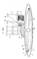
energy driving system 2 is an original driver that may supply kinetic energy to drive an impelledrotary system 3 through a centrifugal terminal to rotate with electric energy or the kinetic energy converted from a fuel. - The impelled
rotary system 3 is provided with anaxis portion 33. Theaxis portion 33 is provided with a radially stretchingportion 34. A centrifugal terminal is formed outside thestretching portion 34. The impelledrotary system 3 at the centrifugal terminal is driven by the kineticenergy driving system 2 to push the centrifugal terminal of impelledrotary system 3 move around along theaxis portion 33. Theaxis portion 33 links with apower generation system 6 through a gearingwheel group system 4. - Further, the impelled
rotary system 3 according to this invention may be designed into a system in a random form, the wind resistance of which is lower; as shown infigure 1 , the centrifugal terminal ofaxis portion 33 is formed into a bigcircular gearing wheel 35. Alternatively, as shown infigure 2 , thestretching portion 34 is formed with an awl-shaped rod 31 or in the shape of an plane wing, or as shown infigure 3 , thestretching portion 34 is formed into acylindrical rod 32 to lower the wind resistance to impelledrotary system 3 moving around. The impelledrotary system 3 may be made of a determined material depending on requirements. - The gearing
wheel group system 4 comprises alarge gearing wheel 41 and asmall gearing wheel 42. Thelarge gearing wheel 41 is connected to and links with theaxis portion 33 of impelledrotary system 3. Thelarge gearing wheel 41 and thesmall gearing wheel 42 may link with each other , in which the large and small gearing wheels may be gears and joggle and link with each other. Further, thesmall gearing wheel 42 is connected to ashaft 60 of thepower generation system 6 and may drive thepower generation system 6 to generate electricity. Next, the gearingwheel group system 4 is to transmit the kinetic energy and vary the constant rotation speed for linking with each system to normally operate, in which it may be a gear or a belt pulley. - The
holder 5 supports and links with each system, as shown infigures 1 and2 illustrating thegearing wheel system 4 and thepower generation system 6, in order to safely run, and may be made of iron. - The kinetic
energy driving system 2 according to this invention shown infigure 1 may be powered with the electric energy as a power source. The kineticenergy driving system 2 is powered with the electric energy supplied by the power supply system (1) provided at the exterior of bigcircular gearing wheel 35 through apower transmission system 11. - In
figure 2 , the kineticenergy driving system 2 is powered with the kinetic energy converted from the fuel energy. In the embodiment, anengine 8 is provided in the kineticenergy driving system 2 and powered with thefuel 81. - At the time of operation, with reference to
figures 1 and2 , depending on a determined height and orientation, each ofsystems 5 is fixed with screws or in other manners onto each holder, as shown infigures 1 and2 illustrating thegearing wheel system 4 and thepower generation system 6. Then, in this invention, the kineticenergy driving system 2 powered with less energy is used to gradually fast impel a centrifugal terminal of therotary system 3 for execution of high-speed rotation. - In this invention, in the principle of contrast between centrifugal and application of force, the driving kinetic energy supplied to the
system 2 is made to increase multiple times, and meanwhile the largegearing wheel system 41 arranged on the axis of rotation center of theimpelled rotation system 3 is used to link with the small gearingwheel group system 42 arranged on the axis of the higherpower generation system 6 to rotate at a high speed, and the power generation is performed at various speed rates of rotation, in which the rates depends on thepower generation system 6. Next, the electric energy is supplied from apower supply unit 61 where thepower generation system 6 is arranged. - Accordingly, the kinetic
energy driving system 2 consuming less energy drives the impelledrotary system 3 to operate, and the gearingwheel group system 4 links with the higherpower generation system 6 to operate and generate electricity for achievement of power saving. - Further, the kinetic
energy driving system 2 according to this invention may be designed into a system in a random form, the wind resistance and friction of which is lower; for example, it may be in the form of a bullet locomotive, an airplane head or the like that brings preferred functions. - With reference to
figure 4 , awheel 26 may be provided at the bottom of kineticenergy driving system 2 according to this invention shown infigures 1 through 3 . In this invention, thepower generation system 6, theholder 5, and the gearingwheel group system 4 are buried in adepressed site 9A of ground. Thewheel 26 at the bottom of kineticenergy driving system 2 may run on theground surface 9B for space saving. Further, the kineticenergy driving system 2 is connected to theimpelled system 3 through aconnector 38. - With reference to
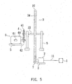
figure 5 and with cross-reference tofigures 1 through 4 , which illustrates a second embodiment of this invention, the impelledrotary system 3 is formed into the impelledrotary system 3 that may arranged vertically, correspondingly as shown infigures 1 through 3 . In the embodiment, the system likewise comprises apower generation system 6, a kineticenergy driving system 2, an impelledrotary system 3, a gearingwheel group system 4, and aholder 5. - The
power generation system 6 is driven to generate electricity. - The kinetic
energy driving system 2 is an original driver that may supply kinetic energy to drive it. In the embodiment, a gearing wheel 7 may be provided at an axis portion of the kineticenergy driving system 2. The impelledrotary system 3 is driven by a centrifugal terminal to rotate with electric energy or the kinetic energy converted from a fuel. Thepower supply system 1 supplies the kineticenergy driving system 2 with the electric power that may be generally electricity, a fuel generator, or an equivalent power supply system in a manner same as that in the first embodiment. - The impelled
rotary system 3 is provided with anaxis portion 33. Theaxis portion 33 is provided with aradially stretching portion 34. A centrifugal terminal is formed outside the stretchingportion 34. Further, agearing wheel 37 is provided at the centrifugal terminal of impelledrotary system 3. Thegearing wheel 37 is coupled with the gearing wheel 7 of kineticenergy driving system 2 and then links. The impelledrotary system 3 at the centrifugal terminal is driven by the kineticenergy driving system 2 to push the centrifugal terminal of impelledrotary system 3 move around along theaxis portion 33. Theaxis portion 33 links with apower generation system 6 through a gearingwheel group system 4. In this invention, in the principle of contrast between the centrifugal and the application of force, the kineticenergy driving system 2 powered with less energy is made to increase multiple times of energy to drive the impelledrotary system 3 and further drive apower generation system 6 powered with higher energy for power generation, thereby economy energy being achieved. - The gearing
wheel group system 4 comprises alarge gearing wheel 41 and asmall gearing wheel 42. Thelarge gearing wheel 41 is connected to and links with theaxis portion 33 of impelledrotary system 3. Thelarge gearing wheel 41 and thesmall gearing wheel 42 may link with each other, in which the large and small gearing wheels may be gears and joggle and link with each other. Further, thesmall gearing wheel 42 is connected to ashaft 60 of thepower generation system 6 and may drive thepower generation system 6 to generate electricity. Next, the gearingwheel group system 4 is to transmit the kinetic energy and vary the constant rotation speed for linking with each system to constantly operate, in which it may be a gear or a belt pulley. - The
holder 5 supports, fixes and links with each system to safely run, and may be made of iron, in whichfigure 5 illustrates only thepower generation system 6, the kineticenergy driving system 2, the impelledrotary system 3, and the gearingwheel group system 4. - In the embodiment, the
power supply system 1 supplies the kineticenergy driving system 2 with the electric power that may be generally electricity, a fuel generator, or an equivalent power supply system in a manner same as that in the first embodiment. - With reference to
figures 6 and7 illustrating a third embodiment of this invention, the device likewise comprises apower generation system 6, a kineticenergy driving system 2, an impelledrotary system 3, a gearingwheel group system 4, and aholder 5. - The impelled
rotary system 3 is generally provided with anaxis portion 33. Theaxis portion 33 is provided with aradially stretching portion 34, as shown infigure 6 . A centrifugal terminal is formed outside the stretchingportion 34. At the centrifugal terminal, a plurality of wind-trend blades 311 are provided. The impelledrotary system 3 at the centrifugal terminal is driven by the kineticenergy driving system 2, as described in detail below, to push the centrifugal terminal of impelledrotary system 3 move around along theaxis portion 33. Theaxis portion 33 links with apower generation system 6 through a gearingwheel group system 4. - The kinetic
energy driving system 2 comprises two power sources, in which a first power source may be afan system 2a. - The
fan system 2a is provided at a location adjacently between the wind-trend blades 311, comprising amotor 22. Themotor 22 links with agearing wheel 43 through ashaft 221 and drives anothergearing wheel 44 of thefan system 2a to further drive anotherblade group 25 provided in thefan system 2a. The wind force generated when theblade group 25 runs may be blown out of anair blowing port 24 provided in thefan system 2a to drive the wind-trend blade 311 and further the impelledrotary system 3 to run. Thefan system 2a is connected to apower transmission system 11. Thepower transmission system 11 is connected to apower supply system 1 as a power supply. - The second power source is provided with an
assistant driving system 2b. Theassistant driving system 2b is likewise connected to thepower transmission system 11, and thepower supply system 1 is used as a power supply. Theassistant driving system 2b comprises amotor 40. Themotor 40 is arranged where ashaft 46 stretches. Theshaft 46 is connected to drive agearing wheel 45. Thegearing wheel 45 links with agearing wheel 47 provided at theaxis portion 33 of the impelledrotary system 3, may drive theaxis portion 33, may assist the first power source, make theaxis portion 33 of impelledrotary system 3 fast run, and generate the centrifugal kinetic energy to lower a load applied to the impelledrotary system 3 and increase the energy of rotation speed. - The gearing
wheel group system 4 comprises alarge gearing wheel 41 and asmall gearing wheel 42. Thelarge gearing wheel 41 is connected to and links with theaxis portion 33 of impelledrotary system 3. Thelarge gearing wheel 41 and thesmall gearing wheel 42 may link with each other to drive thepower generation system 6 for power generation, in which the large and small gearing wheels may be gears and joggle and link with each other. - Accordingly, in the principle of contrast between the centrifugal and the application of force, the kinetic
energy driving system 2 powered with less energy is made to increase multiple times of wind energy to drive the impelledrotary system 3 and further drive apower generation system 6 powered with higher energy for power generation, thereby economy energy being achieved. - The
holder 5 supports, fixes and links with each system to safely run, and may be made of iron. - In the embodiment, the
power supply system 1 may be generally electricity, a fuel generator, or an equivalent power supply system. Further, thepower transmission system 11 comprises electric wires, a switch and the like. The embodiment is implemented in a manner same as that in the first embodiment. - In this invention, the principle of contrast between the centrifugal and the application of force indicates that a torque (moment of force) contrasts with the rotation center apart from an object. From the description made above, the distance of turning radius of an object has relation to the magnitude of a driving force applied to the load and increases with constant magnification. The diameter of axis of the
power generation system 6 does not increase with constant magnification when the generating capacity increases with magnification. Thus, in the principle, the diameter of impelledrotary system 3 according to this invention is higher, the less the energy of kineticenergy driving system 2 is consumed to drive the impelledrotary system 3 and then the higherpower generation system 6 for power generation, energy conservation being thereby achieved. - In the three embodiments of this invention, the principle of contrast of the centrifugal with the application of force and the centrifugally rotary kinetic energy are applied, and thus the lower kinetic
energy driving system 2 is made to drive the impelledrotary system 3 from the centrifugal terminal, link with the gearingwheel group system 4, and then drive the higherpower generation system 6 arranged in the rotation center for power generation and supply. - For example, when the higher
power generation system 6 consumes ten thousand kw to generate electricity, the lower kineticenergy driving system 2 consumes 5 thousand kw to work, and then extra electric energy of 5 thousand kw may be utilized. Regarding practicability of this invention, the spare electric energy may fully be recycled for effective use, which lowers the pollution during power generation and saves energy for energy conservation and environmental protection. - If you have a question on the practicability and structure of this invention, the applicant would like to personally account for this invention to make clear. Alternatively, the applicator provides you with a real object according to this invention for your examination and testing.
- While the invention has been described in terms of what is presently considered to be the most practical and preferred embodiments, it is to be understood that the invention needs not be limited to the disclosed embodiment. On the contrary, it is intended to cover various modifications and similar arrangements included within the spirit and scope of the appended claims which are to be accorded with the broadest interpretation so as to encompass all such modifications and similar structures.
Claims (11)
- A centrifugal driving electricity generation system for energy conservation, comprising:a kinetic energy driving system supplying kinetic energy to drive it;a impelled rotary system being provided with an axis portion provided with a radial portion stretching to a centrifugal terminal, in which the impelled rotary system at the centrifugal terminal is formed with the kinetic energy driving system to drive the centrifugal terminal of impelled rotary system to move around along the axis portion; anda gearing wheel group system comprising a large gearing wheel and a small gearing wheel, in which the large gearing wheel is connected to andlinks with the axis portion of impelled rotary system, the large gearing wheel and the small gearing wheel links with each other, and the small gearing wheel is connected to a shaft of the power generation system and drives the power generation system to generate electricity.
- The centrifugal driving electricity generation system for energy conservation according to claim 1, wherein a holder is provided in more than one of the kinetic energy driving system, impelled rotary system, gearing wheel group system, and power generation system.
- The centrifugal driving electricity generation system for energy conservation according to claim 1, wherein the large gearing wheel is a large gear, the small gearing wheel is a small gear, and the large gearing wheel links with the small gearing wheel by joggling the large and small gears.
- The centrifugal driving electricity generation system for energy conservation according to claim 1, wherein the kinetic energy driving system is connected to a power supply system through a power transmission system and powered.
- The centrifugal driving electricity generation system for energy conservation according to claim 4, wherein the kinetic energy driving system mainly comprises a motor.
- The centrifugal driving electricity generation system for energy conservation according to claim 1, wherein the kinetic energy driving system is provided with an engine and driven by a fuel system with power.
- The centrifugal driving electricity generation system for energy conservation according to claim 1, wherein at the centrifugal terminal, a plurality of wind-trend blades are provided, the kinetic energy driving system comprises two power sources, in which a first power source is a fan system, the fan system is provided at a location adjacently between the wind-trend blades, the wind-trend blade is blown with wind force generated by the fan system to make the impelled rotary system rotate, and the second power source is provided with an assistant driving system that connects to and drives a gearing wheel that links with a gearing wheel provided at the axis portion of impelled rotary system and drives the axis portion to assist the first power source.
- The centrifugal driving electricity generation system for energy conservation according to claim 7, wherein the assistant driving system is connected to a power transmission system and the power transmission system is connected to and powered by the power supply system.
- The centrifugal driving electricity generation system for energy conservation according to claim 7, wherein the fan system comprises a motor that links with a gearing wheel through a shaft and drives a blade group additionally provided in the fan system.
- The centrifugal driving electricity generation system for energy conservation according to claim 1, wherein a gearing wheel is provided in the kinetic energy driving system, a gearing wheel is provided at the centrifugal terminal of impelled rotary system, and the gearing wheel is coupled with the gearing wheel of kinetic energy driving system and then links.
- The centrifugal driving electricity generation system for energy conservation according to claim 1, wherein the kinetic energy driving system is connected to the impelled system through a connector.
Priority Applications (1)
| Application Number | Priority Date | Filing Date | Title |
|---|---|---|---|
| EP20080168133 EP2071713A2 (en) | 2007-12-10 | 2008-10-31 | Centrifugal driving electricity generation system for energy conservation |
Applications Claiming Priority (6)
| Application Number | Priority Date | Filing Date | Title |
|---|---|---|---|
| TW96146949 | 2007-12-10 | ||
| TW97101274 | 2008-01-14 | ||
| TW97115168 | 2008-04-25 | ||
| TW97125609 | 2008-07-07 | ||
| EP08165526 | 2008-09-30 | ||
| EP20080168133 EP2071713A2 (en) | 2007-12-10 | 2008-10-31 | Centrifugal driving electricity generation system for energy conservation |
Publications (1)
| Publication Number | Publication Date |
|---|---|
| EP2071713A2 true EP2071713A2 (en) | 2009-06-17 |
Family
ID=40394242
Family Applications (1)
| Application Number | Title | Priority Date | Filing Date |
|---|---|---|---|
| EP20080168133 Withdrawn EP2071713A2 (en) | 2007-12-10 | 2008-10-31 | Centrifugal driving electricity generation system for energy conservation |
Country Status (1)
| Country | Link |
|---|---|
| EP (1) | EP2071713A2 (en) |
-
2008
- 2008-10-31 EP EP20080168133 patent/EP2071713A2/en not_active Withdrawn
Similar Documents
| Publication | Publication Date | Title |
|---|---|---|
| US20090146427A1 (en) | Centrifugal driving electricity generation system for energy conservation | |
| CN104481806A (en) | Power generating system using wasting energy from moving objects | |
| CN102235293A (en) | Perpendicular throw power generation device of drainage system | |
| GB2471272A (en) | Vertical axis magnus effect wind turbine | |
| CN101397975A (en) | N layer spheroid cavity turbo type wind generator | |
| WO2018103176A1 (en) | Mobile cyclonic vortex generator | |
| CN107054069A (en) | A kind of method that utilization wind energy supplements electric automobile electric power storage | |
| CA2641736A1 (en) | Centrifugal driving electricity generation system for energy conservation | |
| EP2071713A2 (en) | Centrifugal driving electricity generation system for energy conservation | |
| KR100522616B1 (en) | Power generation device using solar energy, magnetic force and wind force | |
| BRPI1104839A2 (en) | energy wind turbine for electric and hybrid vehicles | |
| US20080277937A1 (en) | Torque Motor Type Wind Generator | |
| CN206346870U (en) | Whirlwind turbodynamo is used in one kind movement | |
| CN102865195A (en) | Sail-type hull power generation drive device | |
| CN106988954A (en) | Continental rise is dynamic to turn secondary hydroelectric power system | |
| CN101463880A (en) | Centrifugal motivation energy-saving power generation system | |
| TWI403642B (en) | Wind-power electricity generating device | |
| CN110735765A (en) | Wind power and self-sufficient power generation device | |
| WO2018103183A1 (en) | Intelligent power generation drive device based on magnetic suspension | |
| KR20130062828A (en) | Unwinding improving apparatus for wind power generator | |
| TW200839092A (en) | An energy-saving wind-powered electric generating system using weight-balanced fan | |
| CN202004588U (en) | Power generation device using magnetism | |
| CN1500990A (en) | Electricity generating apparatus having axial flow fan | |
| CN206280197U (en) | A kind of fan blade for wind-driven generator | |
| CN107269462A (en) | A kind of vertical axis aerogenerator |
Legal Events
| Date | Code | Title | Description |
|---|---|---|---|
| PUAI | Public reference made under article 153(3) epc to a published international application that has entered the european phase |
Free format text: ORIGINAL CODE: 0009012 |
|
| AK | Designated contracting states |
Kind code of ref document: A2 Designated state(s): AT BE BG CH CY CZ DE DK EE ES FI FR GB GR HR HU IE IS IT LI LT LU LV MC MT NL NO PL PT RO SE SI SK TR |
|
| AX | Request for extension of the european patent |
Extension state: AL BA MK RS |
|
| STAA | Information on the status of an ep patent application or granted ep patent |
Free format text: STATUS: THE APPLICATION IS DEEMED TO BE WITHDRAWN |
|
| 18D | Application deemed to be withdrawn |
Effective date: 20110503 |