EP2071654A1 - Separator for fuel batteries and fuel batteries - Google Patents
Separator for fuel batteries and fuel batteries Download PDFInfo
- Publication number
- EP2071654A1 EP2071654A1 EP07828524A EP07828524A EP2071654A1 EP 2071654 A1 EP2071654 A1 EP 2071654A1 EP 07828524 A EP07828524 A EP 07828524A EP 07828524 A EP07828524 A EP 07828524A EP 2071654 A1 EP2071654 A1 EP 2071654A1
- Authority
- EP
- European Patent Office
- Prior art keywords
- bipolar plate
- flash
- fuel cell
- bipolar
- mold
- Prior art date
- Legal status (The legal status is an assumption and is not a legal conclusion. Google has not performed a legal analysis and makes no representation as to the accuracy of the status listed.)
- Granted
Links
Images






Classifications
-
- H—ELECTRICITY
- H01—ELECTRIC ELEMENTS
- H01M—PROCESSES OR MEANS, e.g. BATTERIES, FOR THE DIRECT CONVERSION OF CHEMICAL ENERGY INTO ELECTRICAL ENERGY
- H01M8/00—Fuel cells; Manufacture thereof
- H01M8/02—Details
- H01M8/0202—Collectors; Separators, e.g. bipolar separators; Interconnectors
- H01M8/0258—Collectors; Separators, e.g. bipolar separators; Interconnectors characterised by the configuration of channels, e.g. by the flow field of the reactant or coolant
- H01M8/026—Collectors; Separators, e.g. bipolar separators; Interconnectors characterised by the configuration of channels, e.g. by the flow field of the reactant or coolant characterised by grooves, e.g. their pitch or depth
-
- H—ELECTRICITY
- H01—ELECTRIC ELEMENTS
- H01M—PROCESSES OR MEANS, e.g. BATTERIES, FOR THE DIRECT CONVERSION OF CHEMICAL ENERGY INTO ELECTRICAL ENERGY
- H01M8/00—Fuel cells; Manufacture thereof
- H01M8/02—Details
-
- H—ELECTRICITY
- H01—ELECTRIC ELEMENTS
- H01M—PROCESSES OR MEANS, e.g. BATTERIES, FOR THE DIRECT CONVERSION OF CHEMICAL ENERGY INTO ELECTRICAL ENERGY
- H01M4/00—Electrodes
- H01M4/86—Inert electrodes with catalytic activity, e.g. for fuel cells
-
- H—ELECTRICITY
- H01—ELECTRIC ELEMENTS
- H01M—PROCESSES OR MEANS, e.g. BATTERIES, FOR THE DIRECT CONVERSION OF CHEMICAL ENERGY INTO ELECTRICAL ENERGY
- H01M8/00—Fuel cells; Manufacture thereof
- H01M8/02—Details
- H01M8/0202—Collectors; Separators, e.g. bipolar separators; Interconnectors
- H01M8/0258—Collectors; Separators, e.g. bipolar separators; Interconnectors characterised by the configuration of channels, e.g. by the flow field of the reactant or coolant
-
- H—ELECTRICITY
- H01—ELECTRIC ELEMENTS
- H01M—PROCESSES OR MEANS, e.g. BATTERIES, FOR THE DIRECT CONVERSION OF CHEMICAL ENERGY INTO ELECTRICAL ENERGY
- H01M8/00—Fuel cells; Manufacture thereof
- H01M8/02—Details
- H01M8/0202—Collectors; Separators, e.g. bipolar separators; Interconnectors
- H01M8/0258—Collectors; Separators, e.g. bipolar separators; Interconnectors characterised by the configuration of channels, e.g. by the flow field of the reactant or coolant
- H01M8/0263—Collectors; Separators, e.g. bipolar separators; Interconnectors characterised by the configuration of channels, e.g. by the flow field of the reactant or coolant having meandering or serpentine paths
-
- H—ELECTRICITY
- H01—ELECTRIC ELEMENTS
- H01M—PROCESSES OR MEANS, e.g. BATTERIES, FOR THE DIRECT CONVERSION OF CHEMICAL ENERGY INTO ELECTRICAL ENERGY
- H01M8/00—Fuel cells; Manufacture thereof
- H01M8/02—Details
- H01M8/0202—Collectors; Separators, e.g. bipolar separators; Interconnectors
- H01M8/0267—Collectors; Separators, e.g. bipolar separators; Interconnectors having heating or cooling means, e.g. heaters or coolant flow channels
-
- H—ELECTRICITY
- H01—ELECTRIC ELEMENTS
- H01M—PROCESSES OR MEANS, e.g. BATTERIES, FOR THE DIRECT CONVERSION OF CHEMICAL ENERGY INTO ELECTRICAL ENERGY
- H01M8/00—Fuel cells; Manufacture thereof
- H01M8/02—Details
- H01M8/0297—Arrangements for joining electrodes, reservoir layers, heat exchange units or bipolar separators to each other
-
- H—ELECTRICITY
- H01—ELECTRIC ELEMENTS
- H01M—PROCESSES OR MEANS, e.g. BATTERIES, FOR THE DIRECT CONVERSION OF CHEMICAL ENERGY INTO ELECTRICAL ENERGY
- H01M8/00—Fuel cells; Manufacture thereof
- H01M8/10—Fuel cells with solid electrolytes
-
- H—ELECTRICITY
- H01—ELECTRIC ELEMENTS
- H01M—PROCESSES OR MEANS, e.g. BATTERIES, FOR THE DIRECT CONVERSION OF CHEMICAL ENERGY INTO ELECTRICAL ENERGY
- H01M8/00—Fuel cells; Manufacture thereof
- H01M8/24—Grouping of fuel cells, e.g. stacking of fuel cells
- H01M8/241—Grouping of fuel cells, e.g. stacking of fuel cells with solid or matrix-supported electrolytes
-
- H—ELECTRICITY
- H01—ELECTRIC ELEMENTS
- H01M—PROCESSES OR MEANS, e.g. BATTERIES, FOR THE DIRECT CONVERSION OF CHEMICAL ENERGY INTO ELECTRICAL ENERGY
- H01M8/00—Fuel cells; Manufacture thereof
- H01M8/24—Grouping of fuel cells, e.g. stacking of fuel cells
- H01M8/241—Grouping of fuel cells, e.g. stacking of fuel cells with solid or matrix-supported electrolytes
- H01M8/242—Grouping of fuel cells, e.g. stacking of fuel cells with solid or matrix-supported electrolytes comprising framed electrodes or intermediary frame-like gaskets
-
- H—ELECTRICITY
- H01—ELECTRIC ELEMENTS
- H01M—PROCESSES OR MEANS, e.g. BATTERIES, FOR THE DIRECT CONVERSION OF CHEMICAL ENERGY INTO ELECTRICAL ENERGY
- H01M8/00—Fuel cells; Manufacture thereof
- H01M8/24—Grouping of fuel cells, e.g. stacking of fuel cells
- H01M8/2465—Details of groupings of fuel cells
- H01M8/2483—Details of groupings of fuel cells characterised by internal manifolds
-
- H—ELECTRICITY
- H01—ELECTRIC ELEMENTS
- H01M—PROCESSES OR MEANS, e.g. BATTERIES, FOR THE DIRECT CONVERSION OF CHEMICAL ENERGY INTO ELECTRICAL ENERGY
- H01M8/00—Fuel cells; Manufacture thereof
- H01M8/10—Fuel cells with solid electrolytes
- H01M2008/1095—Fuel cells with polymeric electrolytes
-
- H—ELECTRICITY
- H01—ELECTRIC ELEMENTS
- H01M—PROCESSES OR MEANS, e.g. BATTERIES, FOR THE DIRECT CONVERSION OF CHEMICAL ENERGY INTO ELECTRICAL ENERGY
- H01M8/00—Fuel cells; Manufacture thereof
- H01M8/08—Fuel cells with aqueous electrolytes
- H01M8/086—Phosphoric acid fuel cells [PAFC]
-
- H—ELECTRICITY
- H01—ELECTRIC ELEMENTS
- H01M—PROCESSES OR MEANS, e.g. BATTERIES, FOR THE DIRECT CONVERSION OF CHEMICAL ENERGY INTO ELECTRICAL ENERGY
- H01M8/00—Fuel cells; Manufacture thereof
- H01M8/10—Fuel cells with solid electrolytes
- H01M8/1009—Fuel cells with solid electrolytes with one of the reactants being liquid, solid or liquid-charged
- H01M8/1011—Direct alcohol fuel cells [DAFC], e.g. direct methanol fuel cells [DMFC]
-
- Y—GENERAL TAGGING OF NEW TECHNOLOGICAL DEVELOPMENTS; GENERAL TAGGING OF CROSS-SECTIONAL TECHNOLOGIES SPANNING OVER SEVERAL SECTIONS OF THE IPC; TECHNICAL SUBJECTS COVERED BY FORMER USPC CROSS-REFERENCE ART COLLECTIONS [XRACs] AND DIGESTS
- Y02—TECHNOLOGIES OR APPLICATIONS FOR MITIGATION OR ADAPTATION AGAINST CLIMATE CHANGE
- Y02E—REDUCTION OF GREENHOUSE GAS [GHG] EMISSIONS, RELATED TO ENERGY GENERATION, TRANSMISSION OR DISTRIBUTION
- Y02E60/00—Enabling technologies; Technologies with a potential or indirect contribution to GHG emissions mitigation
- Y02E60/30—Hydrogen technology
- Y02E60/50—Fuel cells
Definitions
- the present invention relates to fuel cell bipolar plates, and the fuel cells.
- a fuel cell has a structure normally formed of several tens to several hundreds of unit cells stacked in layers in series.
- a unit cell is a basic configuration unit formed of electrolyte membrane, an electrode and a bipolar plate.
- a fuel cell is fabricated in a method, as follows: The electrolyte membrane and the electrode are previously formed as a membrane electrode assembly (MEA) and thereat the bipolar plate is disposed.
- MEA membrane electrode assembly
- the bipolar plate has cannels formed at at least one surface thereof for supplying hydrogen or a similar fuel, an oxidant formed of air or oxygen, and a coolant cooling the cells, respectively.
- the bipolar plate is required to have sufficient conductivity to ensure electrical connection to an MEA adjacent thereto to allow the fuel cell to generate electric power more efficiently, and in addition thereto, it is also required to have sufficient mechanical strength to support the structure formed of unit cells stacked in layers. Furthermore, as there is a demand for fuel cells reduced in size, there is also a demand for bipolar plates reduced in thickness. Furthermore, there is also a demand for higher precision in thickness in order to reduce contact resistance between the unit cells stacked in layers.
- Conventional fuel cell bipolar plates are formed of a material including resin and a carbon material, and introduced into a compression mold and pressurized and thus molded. Such fuel cell bipolar plates are formed in molds having a variety of structures, as conventionally proposed (see patent documents 1-5 for example.).
- the compression mold is required to be capable of (1) exhausting efficiently and externally the air present in the mold and that present in the material molded and (2) discharging from the mold externally the material to be molded that is excessively introduced into the mold.
- conventional compression molds are configured of a recessed mold half 101 having a recess (a cavity) 101a, and a projected mold half 102 having a projection (a core) 102a, as shown in Fig. 24A , and furthermore, to satisfy items (1), (2) above, recess 101a and projection 102a have sidewalls, respectively, opposite to each other to provide a share edge (a region P in the figure).
- a mold as shown in Fig. 25A , which is a joined-type compression mold configured of mold half 101 having recess 101a and mold half 102 having recess 102a.
- This type of mold is simple in structure and can also be reduced in thickness in total.
- the compression mold having the Fig. 24A conventional share edge structure provides a molded product 120 having resin flash in a direction crossing one surface 120A, as shown in Fig.24B .
- the Fig. 25A conventional, joined-type compression mold provides molded product 120 having resin flash in a direction generally parallel to one surface 120A, as shown in Fig. 25B .
- molded product 120 has resin flash in a direction crossing one surface 120A, as shown in Fig.24B , however, molded products 120 cannot be disposed in sufficient contact with or sufficiently adjacent to one another.
- the plurality of bipolar plates are stacked on one another, they are positioned with a level of precision, which is determined by the molded product's peripheral geometry. If molded product 120 has resin flash in a direction generally parallel to one surface 120A, as shown in Fig. 25B , however, molded products 120 are positioned with poor precision and thus cannot be stacked on one another with high precision.
- the molded product has such resin flash as above not only at an outer peripheral portion thereof but also in the plane of the molded product at a through hole or the like, and the resin flash formed at the through hole prevents the molded products from being brought into sufficient contact with or sufficiently adjacent to one another.
- the present invention has been made in view of such disadvantages as described above, and it contemplates a fuel cell bipolar plates and the fuel cell, that allow molded products to be disposed in sufficient contact with or sufficiently adjacent to one another and also positioned with satisfactory precision and thus stacked on one another and can also dispense with a complicated deflashing step.
- the present invention provides one fuel cell bipolar plate, having one surface having flash projecting from an outer peripheral portion in a direction crossing one surface, and the other surface having a receding portion formed at an outer peripheral portion, and having a geometry capable of accommodating the flash.
- the present invention provides one fuel cell bipolar plate, that has a receding portion formed to be capable of accommodating flash.
- the flash caused at one surface of one bipolar plate is accommodated in a receding portion formed in the other surface of the other bipolar plate.
- the bipolar plates can thus be disposed in sufficient contact with or sufficiently adjacent to each other.
- the flash projects in a direction crossing one surface of the bipolar plate and does not project from a side surface of the bipolar plate toward the outer periphery of the bipolar plate.
- the bipolar plates can thus be positioned with satisfactory precision and thus stacked on one another.
- the present invention provides another fuel cell bipolar plate, having a channel and a manifold that is unconnected to the channel.
- the bipolar plate has one surface having flash projecting from a peripheral portion of the manifold that is unconnected to the channel in a direction crossing one surface.
- the bipolar plate has the other surface having a receding portion that is formed at a peripheral portion of the manifold unconnected to the channel and has a geometry capable of accommodating the flash.
- the flash caused at a peripheral portion of a manifold of one bipolar plate can be accommodated in a receding portion of the other bipolar plate.
- the bipolar plates can thus be disposed in sufficient contact with or sufficiently adjacent to each other.
- the above described one and other bipolar plates preferably have the receding portion forming a step.
- the present invention provides one fuel cell comprising: the above described one or other bipolar plate provided for the fuel cell and another such bipolar plate paired therewith; and a membrane electrode assembly for being stacked alternately with the pair of bipolar plates, wherein one bipolar plate of the pair of the bipolar plates has the flash accommodated in the receding portion of the other bipolar plate of the pair of the bipolar plates.
- One fuel cell of the present invention allows one fuel cell bipolar plate to have flash accommodated in a receding portion of the other fuel cell bipolar plate.
- the bipolar plates can be in sufficient contact with each another.
- the present invention provides another fuel cell comprising: the above described one or other fuel cell bipolar plate; and a membrane electrode assembly for being stacked alternately with the bipolar plate, wherein one bipolar plate has the flash accommodated in the receding portion of the other bipolar plate opposite to one bipolar plate with the membrane electrode assembly interposed.
- the present invention provides the other fuel cell that allows one bipolar plate to have flash accommodated in a receding portion of the other bipolar plate opposite with a membrane electrode assembly interposed.
- the bipolar plates can be disposed sufficiently adjacently.
- the present invention provides still another fuel cell bipolar plate, having a channel and a manifold connected to the channel.
- the manifold is connected to the channel at one surface of a fuel cell bipolar plate and unconnected to the channel at the other surface.
- One surface does not have flash at a connection between the channel and the manifold and the other surface has a receding portion at a peripheral portion of the manifold.
- the receding portion has a recess, and flash that is provided in the recess, and projects from a bottom surface of the recess and does not project from the other surface.
- Still another fuel cell bipolar plate in accordance with the present invention has a recess having a bottom surface having flash in the recess.
- the flash in the recess can have a tip within the recess and thus be prevented from projecting from a second surface of a second bipolar plate toward a first bipolar plate.
- the recess can also accommodate flash of the first bipolar plate.
- one surface at a portion having a channel and a manifold connected to each other does not have flash, and a flow of gas is not prevented between the cannel and the manifold.
- the receding portion is formed in a geometry that can accommodate flash.
- the flash caused at a peripheral portion of a manifold of one bipolar plate is accommodated in a receding portion of a peripheral portion of a manifold of the other bipolar plate.
- the bipolar plates can thus be disposed in sufficient contact with or sufficiently adjacent to each other.
- the present invention provides still another fuel cell comprising: a pair of fuel cell bipolar plates, consisting of one bipolar plate and the other bipolar plate being opposite to each other, one bipolar plate having one surface having flash projecting from an outer peripheral portion of one surface in a direction crossing one surface, the other bipolar plate having the other surface having a receding portion formed at an outer peripheral portion of the other surface, and having a geometry capable of accommodating the flash; and a membrane electrode assembly for being stacked alternately with the pair of bipolar plates.
- the bipolar plate having the flash has the flash accommodated in the receding portion of the bipolar plate having the receding portion.
- Still another fuel cell of the present invention allows one bipolar plate's flash to be accommodated in another bipolar plate's receding portion.
- the bipolar plates can thus be in sufficient contact with each another.
- the present invention provides still another fuel cell, having one surface and the other surface opposite to each other, and having an outer peripheral portion having a portion tapered to reduce a bipolar plate in width in a direction from a side of one surface toward a side of the other surface.
- Still another fuel cell bipolar plate in accordance with the present invention has an outer peripheral portion having a tapered portion.
- the tapered portion can accommodate flash therein.
- the tapered portion can accommodate the flash therein, and the bipolar plates can be disposed in sufficient contact with or sufficiently adjacent to each another.
- a receding portion that can accommodate flash is provided to a fuel cell bipolar plate.
- a fuel cell bipolar plate and the fuel cell can be provided that allow molded products to be disposed in sufficient contact with or sufficiently adjacent to one another and also positioned with satisfactory precision and thus stacked on one another and can also dispense with a complicated deflashing process.
- 1, 1P, 1Q fuel cell bipolar plate, 2a, 2b, 2a 1 , 2a 2 , 2b 1 , 2b 2 : hole for manifold, 3: channel, 4, 4a, 4b: flash, 5a, 5b, 5c, 5d: receding portion, 6: recess, 10: mold, 11, 12: mold member, 21: solid polymer electrolyte membrane, 22: electrode (fuel electrode, oxidant electrode).
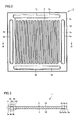
- Fig. 1 and Fig. 2 are a plan view and a rear view, respectively, schematically showing a configuration of a fuel cell bipolar plate in a first embodiment of the present invention.
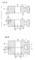
- Fig. 3 is a schematic cross section taken along a line III-III shown in Fig. 1 and Fig. 2 .
- Fig. 4 is a schematic, enlarged cross section of a region Q1 shown in Fig. 3 .
- Fig. 5 is a schematic, enlarged cross section of flash of a region Q2 shown in Fig. 4 .
- a fuel cell bipolar plate 1 has a rectangular, planar geometry and has one surface 1A and the other surface 1B opposite to each other.
- Bipolar plate 1 has holes 2a, 2b for manifolds penetrating between one surface I A and the other surface 1B.
- one surface 1A and the other surface 1B each have a channel 3 formed in communication with holes 2a, 2b for gas or the like.
- One surface 1A at an outer peripheral portion of bipolar plate 1 and at a peripheral portion of hole 2a has flash 4, 4a projecting in a direction crossing one surface 1A. Furthermore, the other surface 1B at an outer peripheral portion of bipolar plate 1 and at a peripheral portion of hole 2a has a receding portion 5a formed to have a geometry that can accommodate each flash 4, 4a.
- the other surface 1B at a peripheral portion of hole 2b has flash 4b projecting in a direction crossing the other surface 1B. Furthermore, one surface 1A at a peripheral portion of hole 2b has receding portion 5a formed to have a geometry that can accommodate flash 4b.
- Each of flash 4, 4a, 4b may exist along the entire outer periphery of bipolar plate 1 and the entire periphery of each of holes 2a, 2b, or may have a portion interrupted. Furthermore, preferably, receding portion 5a is provided along the entire outer periphery of bipolar plate 1 and the entire periphery of each of holes 2a, 2b. However, receding portion 5a may have a portion interrupted.
- Hole 2a for a manifold is connected to channel 3 at the other surface 1B, and hole 2b for a manifold is connected to channel 3 at one surface 1A.
- Holes 2a, 2b have their respective peripheral portions with flash 4a, 4b each at a surface opposite to that having hole 2a, 2b connected to channel 3. Flash 4a, 4b is thus not located between holes 2a, 2b and channel 3 and thus does not prevent a fluid from flowing between the channel and the holes.
- fuel cell bipolar plate 1 may have a hole for a manifold unconnected to channel 3.
- Fig. 26 and Fig. 27 are a plan view and a rear view, respectively, schematically showing a configuration of a fuel cell bipolar plate, that has a manifold unconnected to a channel.
- fuel cell bipolar plate 1 has holes 2a 1 , 2b 1 for manifolds that are connected to channel 3, and in addition thereto holes 2a 2 , 2b 2 for manifolds that are unconnected to channel 3.
- Hole 2a 2 for a manifold unconnected to channel 3 has at one surface 1A a peripheral portion having flash 4a projecting in a direction crossing one surface I A. Furthermore, hole 2a 2 for the manifold unconnected to channel 3 has at the other surface 1B a peripheral portion having receding portion 5a having a geometry that can accommodate flash 4a.
- hole 2b 2 for a manifold unconnected to channel 3 has at the other surface 1B a peripheral portion having flash 4b projecting in a direction crossing the other surface 1B. Furthermore, hole 2b 2 for the manifold unconnected to channel 3 has at one surface 1A a peripheral portion having receding portion 5a having a geometry that can accommodate flash 4b.
- holes 2a 1 , 2b 1 for manifolds connected to channel 3, flash 4a, 4b formed at the holes' respective peripheral portions, and receding portion 5a are substantially identical in configuration to the Fig. 1 and Fig. 2 holes 2a, 2b for manifolds, flash 4a, 4b, and receding portion 5a.
- a configuration in a cross section taken along a line III-III shown in Fig. 26 and Fig. 27 is substantially identical to that shown in Fig. 3 .
- Fig. 26 and Fig. 27 bipolar plate 1 is substantially identical in configuration to that shown in Fig. 1 to Fig. 3 . Accordingly, identical components are denoted by identical reference characters and will not be described repeatedly.
- receding portion 5a is configured by cutting off a corner of bipolar plate I to form a step in cross section. More specifically, with reference to Fig. 1 and Fig. 2 , fuel cell bipolar plate I has an outer peripheral portion having receding portion 5a having a geometry defined by a side surface of bipolar plate I and the other surface 1B that have cut off a corner formed by the side surface and the other surface 1B. Furthermore, hole 2a has a peripheral portion having receding portion 5a having a geometry defined by a wall surface of hole 2a and the other surface 1B that have cut off a corner formed by the wall surface and the other surface 1B. Furthermore, hole 2b has a peripheral portion having receding portion 5a having a geometry defined by a wall surface of hole 2b and one surface 1A that have cut off a corner formed by the wall surface and one surface 1A.
- Flash 4 has the other side surface formed of a surface continuing to the bipolar plate's side surface. Flash 4 has the radius of curvature r of at least 0.05 mm and at most 0.15 mm, a thickness t of at least 0.02 mm and at most 0.1 mm, and a height h of at least 0.05 mm and at most 0.15 mm.
- flash 4 has the radius of curvature r of less than 0.05 mm, it would be difficult to process the mold for molding. If flash 4 has the radius of curvature r exceeding 0.15 mm, flash 4 is excessively large. If flash 4 has thickness t of less than 0.02 mm, it would be difficult to exhaust air present in a material to be molded and the resultant molded product may have voids therein. If flash 4 has thickness t exceeding 0.1 mm, the material to be molded would leak in an increased amount resulting in a molded product unstable in thickness. Flash 4 has height h determined by the magnitude of the radius of curvature r of flash 4 described above. Note that flash 4a, 4b is similar in geometry to flash 4 described above.
- Receding portion 5a shown in Fig. 4 is basically only required to have a size that can accommodate flash 4, 4a, 4b. If receding portion 5a has a step, as provided in the present embodiment, receding portion 5a is only required to have the step with a dimension H equal to or larger than height h of flash 4, 4a, 4b (i.e., H ⁇ h), and, as seen in a direction along the other surface 1B of bipolar plate 1, a width T equal to or larger than a sum of thickness t of flash 4, 4a, 4b and the radius of curvature r of flash 4, 4a, 4b (i.e., T ⁇ t + r). Note that preferably dimensions H, T have an upper limit set to be a dimension that does not affect the molded product in geometry, and stability in dimension.
- Fig. 6 is a schematic cross section of the Fig. 4 bipolar plate stacked on another such bipolar plate.
- Fig. 7 is a schematic, enlarged cross section of a region Q3 shown in Fig. 6 .
- bipolar plate 1 is stacked on another such bipolar plate, more than one bipolar plate 1 shown in Fig. 4 is prepared. (For example, two such bipolar plates are prepared.) These bipolar plates 1 are positioned, and thereafter stacked on one another, as shown in Fig. 6 . With the bipolar plates thus stacked, receding portion 5a is located at a position corresponding to that having flash 4, 4a, 4b, as has been described above, and as receding portion 5a has a dimension that can accommodate each flash 4, 4a, 4b, flash 4, 4a, 4b is each accommodated in receding portion 5a, as shown in Fig. 6 and Fig. 7 .
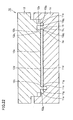
- Fig. 8 is a cross section schematically showing a configuration of a mold employed to mold the fuel cell bipolar plate in the first embodiment of the present invention.
- Fig. 9 is a schematic, enlarged cross section of a region Q4 shown in Fig. 8 .
- a mold 10 for molding is a mold employed to mold a material to be molded and has a mold member 11 and a mold member 12.
- Mold member 11 has a surface facing mold member 12 and having a recess 11a.
- Mold member 12 has a surface facing mold member 11 and having a projection 12a provided to correspond to recess 11a.
- Recess 11a and projection 12a are configured such that when mold members 11 and 12 are joined together recess 11a of mold member 11 receives projection 12a of mold member 12.
- Mold member 11 has recess 11a having a bottom surface 11a 1 having a channel forming projection 11d for forming a channel for gas or the like, and a hole forming projection 11b and a hole forming recess 11c for forming a hole for a manifold.
- Mold member 12 has projection 12a having a top surface 12a 1 opposite to bottom surface 11a 1 of recess 11a.
- Top surface 12a 1 has a channel forming projection 12d for forming a channel for gas or the like, and a hole forming recess 12b and a hole forming projection 12c for forming a hole for a manifold.
- the mold member 11 hole forming projection 11b is provided to correspond to the mold member 12 hole forming recess 12b and the mold member 11 hole forming recess 11c is provided to correspond to the mold member 12 hole forming projection 12c.
- Mold member 11 has recess 11a having a peripheral portion surrounded by a receding portion forming projection 11e 1 . Furthermore, hole forming projection 11b has a foot having a peripheral portion surrounded by a receding portion forming projection 11f 1 , and hole forming projection 12c has a foot having a peripheral portion surrounded by a receding portion forming projection 12f 1 .
- These receding portion forming projections 11e 1 , 11f 1 , 12f 1 are each for example a pointed step in cross section.
- the present embodiment's fuel cell bipolar plate 1 is produced in a method, as will be described hereinafter.
- a material to be molded is prepared for example to include at least a conductive carbon material and a resin binder.
- the resin binder for example includes at least one of thermoplastic resin and thermosetting resin.
- the material to be molded may be in the form of powder, particles, pellets or the like, or it may be in the form of a sheet.
- the carbon material for example includes artificial graphite, natural graphite, glassy carbon, carbon black, acetylene black, ketjen black and the like. These carbon materials can be used singly or two or more types thereof can be used in combination. These carbon materials in the form of powder/particles are not limited in geometry: they may be any in form of foil, a scale, a plate, a needle, a sphere, or an amorphous form. Furthermore, graphite that is chemically treated, i.e., exfoliated graphite, can also be used. When conductivity is considered, artificial graphite, natural graphite, and exfoliated graphite are preferable, as they can be used in a smaller amount to provide a bipolar plate having high conductivity.
- thermosetting resin can include for example phenol resin, epoxy resin, vinyl ester resin, urea resin, melamine resin, unsaturated polyester resin, silicone resin, diallyl phthalate resin, maleimide resin, polyimide resin, and the like.
- the thermosetting resin may be formed of not only one type of resin but also two or more types of resins mixed together.
- the thermoplastic resin can include for example polyethylene, polypropylene, cycloolefin polymer, polystyrene, syndiotactic polystyrene, polyvinyl chloride, ABS resin, polyamide resin, polyacetals, polycarbonate, polyphenylene ether, denaturated polyphenylene ether, polyethylene terephthalate, polytrimethylene terephthalate, polybutylene terephthalate, polycyclohexylene terephthalate, polyphenylene sulfide, polythioether sulfone, polyether ether ketone, polyarylate, polysulfone, polyethersulfone, polyetherimide, polyamideimide, thermoplastic polyimide, liquid crystal polymer, polytetrafluoroethylene copolymer, polyvinylidene fluoride, and similar fluorine resins; wholly aromatic polyester, semi aromatic polyester, poly lactic acid, polyester-polyester elastomer, polyester-poly
- the material to be molded is introduced into the Fig. 8 mold 10 and pressurized between mold member 11 and mold member 12. In doing so, mold members 11 and 12 are heated by a heat platen (not shown) and through mold members 11 and 12 the material to be molded is heated. If the resin binder contains the thermosetting resin, thus heating and pressurizing the material sets the thermosetting resin. Subsequently, fuel cell bipolar plate (or a molded product) I that is shown in Fig. 1 to Fig. 3 is removed from mold 10. If the resin binder contains the thermoplastic resin, then, thus heating and pressurizing the material melts the thermoplastic resin.
- thermoplastic resin contains the thermoplastic resin
- mold members 11 and 12 are cooled by a cooling platen (not shown).
- the material to be molded is still pressurized between mold member 11 and mold member 12.
- cooling and pressurizing sets the melted thermoplastic resin.
- fuel cell bipolar plate (or a molded product) I that is shown in Fig. 1 to Fig. 3 is removed from mold 10.
- the material to be molded is heated and pressurized in mold 10 to obtain fuel cell bipolar plate (or molded product) 1
- the resin binder is formed of the thermoplastic resin or the thermoplastic resin and the thermosetting resin then the material to be molded is heated and pressurized in mold 10 and cooled and pressurized in mold 10 to obtain fuel cell bipolar plate (or molded product) 1.
- the Fig. 8 mold 10 will cause flash between a side surface of recess 11a and that of projection 12a (i.e., at a region P1), between hole forming recess 12b and hole forming projection 11b (i.e., at a region P2), and between hole forming recess 11c and hole forming projection 12c (i.e., at a region P3).
- the present embodiment provides a function and effect, as will be described hereinafter.
- the present embodiment provides a fuel cell bipolar plate with receding portion 5a formed to have a geometry that can accommodate each flash 4, 4a, 4b.
- a fuel cell bipolar plate with receding portion 5a formed to have a geometry that can accommodate each flash 4, 4a, 4b.
- one bipolar plate 1 has its flash 4, 4a, 4b accommodated by the other bipolar plate 1 in receding portion 5a.
- Bipolar plates 1 can thus be disposed in sufficient contact with or sufficiently adjacent to one another.
- flash 4, 4a, 4b projects in a direction crossing the bipolar plate 1 one surface 1A or the other surface 1B, rather than from the bipolar plate 1 side surface toward its outer periphery.
- Bipolar plates 1 can thus be positioned with satisfactory precision and thus stacked on one another.
- Fig. 10 is a partially exploded cross section schematically showing a configuration of a fuel cell bipolar plate in a second embodiment of the present invention.
- Fig. 11 is a schematic cross section of the Fig. 10 bipolar plate stacked on another such bipolar plate.
- Fig. 12 is a schematic, enlarged cross section of a region Q5 shown in Fig. 11
- the present embodiment provides fuel cell bipolar plate 1, that has a receding portion different in geometry from that of the first embodiment.
- the present embodiment provides bipolar plate I having an outer peripheral portion having a receding portion 5b notched to taper to reduce bipolar plate 1 in width in a direction from a side of one surface I A of bipolar plate 1 toward a side of the other surface 1B of bipolar plate 1.
- bipolar plate 1 has one surface 1A having a width W1 and the other surface 1B having a width W2 smaller than width W1.
- hole 2b has a peripheral portion having receding portion 5b notched to taper to allow hole 2b to have an aperture having a diameter increased as seen in a direction from a side of the other surface 1B of bipolar plate I toward a side of one surface 1A of bipolar plate 1.
- hole 2a has a peripheral portion having receding portion 5b notched to taper to allow hole 2a to have an aperture having a diameter increased as seen in a direction from a side of one surface 1A of bipolar plate 1 toward a side of the other surface 1B of bipolar plate 1.
- These tapering notches each have a linearly extending portion in the cross sections shown in Fig. 10 to Fig. 12 .
- these receding portions 5b are each basically only required to have a dimension that can accommodate flash 4, 4a, 4b. If bipolar plate 1 has an outer peripheral portion having receding portion 5b notched to taper, as described in the present embodiment, and a tapering angle ⁇ (an angle formed by the other surface 1B and a tapered surface) shown in Fig. 12 is for example 45°, receding portion 5b is only required to have width T and height H each equal to or larger than a sum of thickness t of flash 4 and the radius of curvature r of flash 4 shown in Fig.
- Receding portion 5b tapered as it is notched has width T for example of at least 0.07 mm and at most 0.25 mm and height H for example of at least 0.07 mm.
- Receding portion 5b formed at the peripheral portion of each hole 2a, 2b is similar in geometry to receding portion 5b formed at the outer peripheral portion of bipolar plate 1 described above. Note that preferably dimensions H, T have an upper limit set to be a dimension that does not affect the molded product in geometry, and stability in dimension.
- tapering notch may taper all the way from one surface I A to the other surface 1B, as shown in Fig. 28 .
- bipolar plate 1 at an outer peripheral portion thereof has a side surface entirely notched and thus tapered, and holes 2a, 2b for manifolds each have a wall surface entirely notched and thus tapered.
- the fuel cell bipolar plate according to the present embodiment is substantially identical in configuration to that according to the first embodiment. Accordingly, identical components are identically denoted and will not be described repeatedly.
- bipolar plate 1 is stacked on another such bipolar plate, more than one bipolar plate 1 shown in Fig. 10 is prepared. (For example, two such bipolar plates are prepared.) These bipolar plates 1 are positioned, and thereafter stacked on one another, as shown in Fig. 11 and Fig. 12 . With the bipolar plates thus stacked, receding portion 5b is located at a position corresponding to that having flash 4, 4a, 4b, as has been described above, and as receding portion 5b has a dimension that can accommodate flash 4, 4a, 4b, flash 4, 4a, 4b is each accommodated in receding portion 5b, as shown in Fig. 11 and Fig. 12 .
- Fig. 13 is a cross section schematically showing a configuration of a mold employed to mold the fuel cell bipolar plate in the second embodiment of the present invention, the configuration having shown enlarged a portion corresponding to region Q4 shown in Fig. 8 .
- Mold 10 in the present embodiment is different in configuration from the mold in the first embodiment as shown in Fig. 8 and Fig. 9 in that they have receding portion forming projections, respectively, that are different in geometry for forming different receding portions.
- the present embodiment provides mold 10 such that mold member 11 has recess 11a having a peripheral portion surrounded by a receding portion forming projection 11e 2 tapered in cross section, hole forming projection 11b has a foot having a peripheral portion surrounded by a receding portion forming projection (not shown) tapered in cross section, and hole forming projection 12c has a foot having a peripheral portion surrounded by a receding portion forming projection 12f 2 tapered in cross section.
- mold 10 in the present embodiment is substantially identical in configuration to mold 10 in the first embodiment. Accordingly, identical components are identically denoted and will not be described repeatedly. Furthermore, the method that employs mold 10 as described above to produce fuel cell bipolar plate I in the present embodiment is also substantially identical to the method described in the first embodiment. Accordingly, it will not be described repeatedly.
- the present embodiment also provides fuel cell bipolar plate 1, that can achieve a function and effect similar to that of the first embodiment.
- Fig. 14 is a schematic cross section of a configuration of a fuel cell bipolar plate in a third embodiment of the present invention, the configuration having shown enlarged a portion corresponding to region Q1 shown in Fig. 3 .
- Fig. 15 is a schematic cross section of the Fig. 14 bipolar plate stacked on another such bipolar plate.
- Fig. 16 is a schematic, enlarged cross section of a region Q6 shown in Fig. 15 .
- the present embodiment provides fuel cell bipolar plate 1, that is different from that of the first embodiment in the receding portion's geometry.
- a receding portion 5c is notched to allow bipolar plate 1 to have an outer peripheral portion having a corner with a radius of curvature R and holes 2a, 2b to have a peripheral portion having a corner with the radius of curvature R.
- the radius of curvature R of receding portion 5c is larger than the radius of curvature r of flash 4.
- receding portion 5c is only required to have a dimension that can accommodate flash 4. If receding portion 5c has the radius of curvature R, as described in the present embodiment, then, as shown in Fig. 16 , the radius of curvature R of receding portion 5c is only required to be equal to or larger than a sum of three times the radius of curvature r of flash 4 and thickness t of flash 4 (i.e., R ⁇ 3 x r + t). Note that preferably the radius of curvature R has an upper limit set to avoid affecting the molded product in geometry, and stability in dimension.
- fuel cell bipolar plate 1 in the present embodiment is substantially identical in configuration to that in the first embodiment. Accordingly, identical components are identically denoted and will not be described repeatedly.
- bipolar plate 1 is stacked on another such bipolar plate, more than one bipolar plate 1 shown in Fig. 14 is prepared. (For example, two such bipolar plates are prepared.) These bipolar plates 1 are positioned, and thereafter stacked on one another, as shown in Fig. 15 and Fig. 16 . With the bipolar plates thus stacked, receding portion 5c is located at a position corresponding to that having flash 4, 4a, 4b, as has been described above, and as receding portion 5c has a dimension that can accommodate flash 4, 4a, 4b, flash 4, 4a, 4b is accommodated in receding portion 5c, as shown in Fig. 15 and Fig. 16 .
- Fig. 17 is a cross section schematically showing a configuration of a mold employed to mold the fuel cell bipolar plate in the third embodiment of the present invention, the configuration having shown enlarged a portion corresponding to region Q4 shown in Fig. 8 .
- Mold 10 in the present embodiment is different in configuration from the mold in the first embodiment as shown in Fig. 8 and Fig. 9 in that they have receding portion forming projections, respectively, that are different in geometry for forming different receding portions.
- Fig. 8 and Fig. 9 have receding portion forming projections, respectively, that are different in geometry for forming different receding portions.
- the present embodiment provides mold 10 such that mold member 11 has recess 11a having a peripheral portion surrounded by a receding portion forming projection 11e 3 round to have the radius of curvature R in cross section, hole forming projection 11b has a foot having a peripheral portion surrounded by a receding portion forming projection (not shown) round to have the radius of curvature R in cross section, and hole forming projection 12c has a foot having a peripheral portion surrounded by a receding portion forming projection 12f 3 round to have the radius of curvature R in cross section.
- mold 10 in the present embodiment is substantially identical in configuration to that in the first embodiment. Accordingly, identical components are identically denoted and will not be described repeatedly. Furthermore, the method that employs mold 10 as described above to produce fuel cell bipolar plate 1 in the present embodiment is also substantially identical to the method described in the first embodiment. Accordingly, it will not be described repeatedly.
- the present embodiment also provides fuel cell bipolar plate 1, that can achieve a function and effect similar to that of the first embodiment.
- bipolar plates 1 may be stacked such that their surfaces that have flash 4 face each other, as shown in Fig. 18 .
- flash 4 prevents bipolar plates 1 from being in sufficient contact with or sufficiently adjacent to one another.
- a recess 6 is provided at a portion having flash 4, as shown in Fig. 19 .
- the present embodiment provides a fuel cell bipolar plate, that is configured, as will be described hereinafter more specifically.
- Fig. 19 is a schematic cross section of two fuel cell bipolar plates in a fourth embodiment of the present invention, with a portion that corresponds to region Q1 of Fig. 3 shown enlarged.
- Fig. 20 shows in a schematic cross section the Fig. 19 two bipolar plates stacked on each other.
- Fig. 21 is a schematic, enlarged cross section of a region Q7 shown in Fig. 20 .
- first and second fuel cell bipolar plates 1P, 1Q are stacked on each other. Similarly as described in the first embodiment, these first and second bipolar plates 1P, 1Q each have holes 2a (not shown), 2b for manifolds.
- First bipolar plate 1P has a surface 1B 1 facing second bipolar plate 1Q and having an outer peripheral portion having flash 4 projecting in a direction crossing surface 1B 1 .
- Second bipolar plate 1Q has a surface 1A 2 facing first bipolar plate 1P and having an outer peripheral portion having a receding portion 5d capable of accommodating flash 4.
- bipolar plate 1Q has a surface 1B 2 having receding portion 5d located at a peripheral portion of hole 2b to be capable of accommodating flash 4. Furthermore, although not shown, bipolar plate 1Q has surface 1A 2 having receding portion 5d located at a peripheral portion of hole 2a to be capable of accommodating flash 4.
- These receding portions 5d are configured of recess 6 and flash 4c provided in the recess and projecting from a bottom surface of recess 6.
- Recess 6 has a depth D equal to or larger than a sum of a height h 1 of flash 4c in the recess and height h of flash 4 (i.e., D ⁇ h 1 + h).
- height h 1 of flash 4c in the recess is smaller than depth D of recess 6 and thus will not project outside recess 6 (i.e., from surface 1A 2 or surface 1B 2 ).
- recess 6 has width T equal to or larger than a sum of width t of flash 4c in the recess, a radius of curvature r 1 of flash 4c in the recess, and a radius of curvature r 2 opposite thereto (i.e., T ⁇ t + r 1 + r 2 ).
- the first bipolar plate 1P surface 1A 1 does not have flash, a receding portion for accommodating the flash, or the like.
- first and second bipolar plates 1P, 1Q in the present embodiment are substantially identical in configuration to bipolar plate I of the first embodiment described above. Accordingly, identical components are identically denoted and will not be described repeatedly.
- first and second fuel cell bipolar plates 1P cell are mutually positioned and thereafter stacked on one another, as shown in Fig. 20 and Fig. 21 .
- receding portion 5d has recess 6 located at a position corresponding to that having flash 4, as has been described above, and as recess 6 also has a dimension that can accommodate flash 4, flash 4 is accommodated in receding portion 5d at recess 6.
- bipolar plate 1Q may have one surface (e.g., one surface 1A 2 ) alone having channel 3 and may not have the other surface 1B 2 having channel 3.
- the surface (i.e., the other surface 1B 2 ) opposite to that (i.e., one surface 1A 2 ) at which holes 2a (not shown), 2b for manifolds are each connected to channel 3 has receding portion 5d formed at a peripheral portion of each of holes 2a (not shown), 2b for manifolds.
- Fig. 29 is a cross section of a portion at which a hole for a manifold is connected to a channel on one surface.
- Fig. 22 is a cross section schematically showing a configuration of a mold employed to mold a second fuel cell bipolar plate in the fourth embodiment of the present invention.
- mold 10 is a mold employed to mold a material to be molded and has mold member 11 and mold member 12.
- Mold member 11 has a surface facing mold member 12 and having recess 11a.
- Mold member 12 has a surface facing mold member 11 and having projection 12a provided to correspond to recess 11a.
- Recess 11a and projection 12a are configured such that when mold members 11 and 12 are joined together recess 11a of mold member 11 receives projection 12a of mold member 12.
- Mold member 11 has recess 11a having bottom surface 11a 1 having channel forming projection 11d for forming a channel for gas or the like, and hole forming projection 11b and hole forming recess 11c for forming a hole for a manifold.
- Mold member 12 has projection 12a having top surface 12a 1 opposite to bottom surface 11a 1 of recess 11a.
- Top surface 12a 1 has channel forming projection 12d for forming a channel for gas or the like, and hole forming recess 12b and hole forming projection 12c for forming a hole for a manifold.
- the mold member 11 hole forming projection 11b is provided to correspond to the mold member 12 hole forming recess 12b and the mold member 11 hole forming recess 11c is provided to correspond to the mold member 12 hole forming projection 12c.
- Mold member 12 has projection 12a having an outer peripheral portion surrounded by a receding portion forming projection 12g 1 provided at top surface 12a 1 . Furthermore, hole forming recess 12b has a peripheral portion surrounded by a receding portion forming projection 12g 2 provided at top surface 12a 1 . Furthermore, hole forming recess 11c has a peripheral portion surrounded by a receding portion forming projection 11g provided at bottom surface 11a 1 . These receding portion forming projections 12g 1 , 12g 2 , 11g are each for example a pointed step in cross section.
- the method that employs mold 10 as described above to produce second fuel cell bipolar plate 1Q in the present embodiment is substantially identical to the method employed to produce bipolar plate 1 in the first embodiment. Accordingly, it will not be described repeatedly.
- the present embodiment also provides bipolar plates 1P, 1Q that can achieve a function and effect similar to that of the first embodiment.
- a bipolar plate having one surface having flash and the other surface having a receding portion which corresponds to the first to third embodiments, is preferable to a pair of a bipolar plate having one surface having flash and a bipolar plate having one surface opposite to the paired bipolar plate and having a receding portion accommodating the flash, which corresponds to the fourth embodiment, in that the former can be produced in a single mold.
- Bipolar plate 1 (or 1P, 1Q) obtained as described above in the first to fourth embodiments can be used to fabricate a fuel cell.
- Fig. 23A, Fig. 23B and Fig. 23C are each an exploded cross section schematically showing a fuel cell different in configuration.
- the fuel cell has at least a pair of bipolar plates 1 described in the first to third embodiment, and the pair of bipolar plates 1, 1 and a membrane electrode assembly are alternately stacked to configure the fuel cell.
- the membrane electrode assembly is configured for example of a solid polymer electrolyte membrane 21 and a pair of electrodes 22, 22 serving as a fuel electrode and an oxidant electrode and sandwiching solid polymer electrolyte membrane 21.
- the pair of bipolar plates 1, 1 has one bipolar plate 1 having flash 4 and the other bipolar plate 1 having receding portion 5a (or 5b, 5c) accommodating flash 4.
- the fuel cell includes bipolar plate 1 described in the first to third embodiments, and bipolar plate 1 and a membrane electrode assembly are alternately stacked to configure the fuel cell.
- Bipolar plate 1 has flash 4 accommodated in receding portion 5a (or 5b, 5c) of bipolar plate 1 opposite with the membrane electrode assembly posed therebetween.
- the fuel cell is configured of a pair of bipolar plates 1P, 1Q of the fourth embodiment and a membrane electrode assembly alternately stacked.
- the pair of bipolar plates has bipolar plate 1P having one surface having an outer peripheral portion having flash 4 projecting in a direction crossing the surface.
- the pair of bipolar plates has bipolar plate 1Q having one surface having an outer peripheral portion having receding portion 5d having a geometry that can accommodate flash 4.
- the pair of bipolar plates 1P, 1Q is stacked such that a surface having flash 4 and that having receding portion 5d face each other. Flash 4 of bipolar plate 1P is thus accommodated in receding portion 5d of bipolar plate 1Q.
- Fig. 23A to Fig. 23C do not show a hole for a manifold for the sake of convenience for illustration.
- bipolar plate 1 in each of Fig. 26 and Fig. 27 may be stacked as bipolar plate I in Fig. 23A , and furthermore, may be stacked as bipolar plate 1 in Fig. 23B .
- bipolar plate 1 in Fig. 28 may be stacked as bipolar plate 1 in Fig. 23A , and furthermore, may be stacked as bipolar plate 1 in Fig. 23B .
- bipolar plate 1Q in Fig. 29 may be stacked as bipolar plate 1Q in Fig. 23C together with another bipolar plate 1P.
- the fuel cell is provided as a stack of cells configured of bipolar plates and an MEA and disposed in series for the purpose of increasing its performance to generate electric power.
- the fuel cell provided as a stack of cells, as described above, may have a coolant passed between the cells, and in that case, as shown in Fig. 23A and Fig. 23C , bipolar plate 1 (or 1P, 1Q) is provided with a coolant channel 3 passing the coolant.
- a type of miniature fuel cell used for a mobile phone or the like is a fuel cell having a stacked structure that does not have a coolant channel passing a coolant, and this fuel cell will be structured of a bipolar plate and a membrane electrode assembly alternately stacked in layers, as shown in Fig. 23B .
- paired bipolar plates sandwiching a coolant channel are equal in potential, and accommodating flash in a receding portion allows the bipolar plates to be in sufficient contact with each other.
- Paired bipolar plates I sandwiching a membrane electrode assembly as shown in Fig. 23B , will be opposite in potential, (i.e., associated with an anode and a cathode) and thus cannot be brought into contact with each other.
- accommodating flash in a receding portion allows the bipolar plates to be disposed sufficiently adjacently.
- Such a fuel cell has hydrogen gas or methanol or the like ionized at a fuel electrode 22 and thereafter passing through solid polymer electrolyte membrane 21 to react at an oxidant electrode 22 with oxygen or the like in the air and thus generate electric power.
- the present embodiment can provide a fuel cell bipolar plate, that is suitably applicable to the above described solid polymer fuel cell and in addition a hydrazine fuel cell, a direct methanol fuel cell, an alkaline fuel cell, a phosphoric acid fuel cell and a like, variety of fuel cells.
- the present invention is advantageously applicable particularly to a fuel cell bipolar plate and a fuel cell employing the bipolar plate, that can be used for a phosphoric acid fuel cell, a direct methanol fuel cell, a solid polymer fuel cell and a similar fuel cell applied to a power supply for an electric vehicle, a portable power supply, a power supply for emergency, and the like.
Landscapes
- Chemical & Material Sciences (AREA)
- Chemical Kinetics & Catalysis (AREA)
- Electrochemistry (AREA)
- General Chemical & Material Sciences (AREA)
- Life Sciences & Earth Sciences (AREA)
- Engineering & Computer Science (AREA)
- Manufacturing & Machinery (AREA)
- Sustainable Development (AREA)
- Sustainable Energy (AREA)
- Fuel Cell (AREA)
Abstract
Description
- The present invention relates to fuel cell bipolar plates, and the fuel cells.
- In recent years, fuel cells obtaining electric power from an electrochemical reaction of hydrogen and oxygen are studied for a variety of applications such as portable equipment, automobiles and the like. A fuel cell has a structure normally formed of several tens to several hundreds of unit cells stacked in layers in series. A unit cell is a basic configuration unit formed of electrolyte membrane, an electrode and a bipolar plate. Generally, a fuel cell is fabricated in a method, as follows: The electrolyte membrane and the electrode are previously formed as a membrane electrode assembly (MEA) and thereat the bipolar plate is disposed. The bipolar plate has cannels formed at at least one surface thereof for supplying hydrogen or a similar fuel, an oxidant formed of air or oxygen, and a coolant cooling the cells, respectively.
- The bipolar plate is required to have sufficient conductivity to ensure electrical connection to an MEA adjacent thereto to allow the fuel cell to generate electric power more efficiently, and in addition thereto, it is also required to have sufficient mechanical strength to support the structure formed of unit cells stacked in layers. Furthermore, as there is a demand for fuel cells reduced in size, there is also a demand for bipolar plates reduced in thickness. Furthermore, there is also a demand for higher precision in thickness in order to reduce contact resistance between the unit cells stacked in layers.
- Conventional fuel cell bipolar plates are formed of a material including resin and a carbon material, and introduced into a compression mold and pressurized and thus molded. Such fuel cell bipolar plates are formed in molds having a variety of structures, as conventionally proposed (see patent documents 1-5 for example.).
- The compression mold is required to be capable of (1) exhausting efficiently and externally the air present in the mold and that present in the material molded and (2) discharging from the mold externally the material to be molded that is excessively introduced into the mold.
- Generally, conventional compression molds are configured of a
recessed mold half 101 having a recess (a cavity) 101a, and a projectedmold half 102 having a projection (a core) 102a, as shown inFig. 24A , and furthermore, to satisfy items (1), (2) above, recess 101a andprojection 102a have sidewalls, respectively, opposite to each other to provide a share edge (a region P in the figure). - When such a mold is employed to mold a material to be molded 120a, the material that is excessive flows out of
recess 101 a and is discharged into a gap (or clearance) of the share edge and the mold and the material can also have their internal air exhausted out of the mold efficiently. - Furthermore, there is also a mold, as shown in
Fig. 25A , which is a joined-type compression mold configured ofmold half 101 havingrecess 101a andmold half 102 havingrecess 102a. This type of mold is simple in structure and can also be reduced in thickness in total. - Patent Document 1: Japanese Patent Laying-open No.
2001-198921 - Patent Document 2: Japanese Patent Laying-open No.
2003-170459 - Patent Document 3: Japanese Patent Laying-open No.
2004-230788 - Patent Document 4: Japanese Patent Laying-open No.
2004-71334 - Patent Document 5: Japanese Patent No.
3751911 - The compression mold having the
Fig. 24A conventional share edge structure, however, provides a moldedproduct 120 having resin flash in a direction crossing onesurface 120A, as shown inFig.24B . Furthermore, theFig. 25A conventional, joined-type compression mold provides moldedproduct 120 having resin flash in a direction generally parallel to onesurface 120A, as shown inFig. 25B . - When a fuel cell has a plurality of bipolar plates (or molded products) stacked on one another, it is necessary to dispose the molded products in sufficient contact with or sufficiently adjacent to one another. If molded
product 120 has resin flash in a direction crossing onesurface 120A, as shown inFig.24B , however, moldedproducts 120 cannot be disposed in sufficient contact with or sufficiently adjacent to one another. - Furthermore, when the plurality of bipolar plates (or molded products) are stacked on one another, they are positioned with a level of precision, which is determined by the molded product's peripheral geometry. If molded
product 120 has resin flash in a direction generally parallel to onesurface 120A, as shown inFig. 25B , however, moldedproducts 120 are positioned with poor precision and thus cannot be stacked on one another with high precision. - Furthermore, the molded product has such resin flash as above not only at an outer peripheral portion thereof but also in the plane of the molded product at a through hole or the like, and the resin flash formed at the through hole prevents the molded products from being brought into sufficient contact with or sufficiently adjacent to one another.
- Furthermore, removing such resin flash requires a complicated deflashing step.
- The present invention has been made in view of such disadvantages as described above, and it contemplates a fuel cell bipolar plates and the fuel cell, that allow molded products to be disposed in sufficient contact with or sufficiently adjacent to one another and also positioned with satisfactory precision and thus stacked on one another and can also dispense with a complicated deflashing step.
- The present invention provides one fuel cell bipolar plate, having one surface having flash projecting from an outer peripheral portion in a direction crossing one surface, and the other surface having a receding portion formed at an outer peripheral portion, and having a geometry capable of accommodating the flash.
- The present invention provides one fuel cell bipolar plate, that has a receding portion formed to be capable of accommodating flash. When bipolar plates identical in geometry are stacked on one another, the flash caused at one surface of one bipolar plate is accommodated in a receding portion formed in the other surface of the other bipolar plate. The bipolar plates can thus be disposed in sufficient contact with or sufficiently adjacent to each other.
- Furthermore, the flash projects in a direction crossing one surface of the bipolar plate and does not project from a side surface of the bipolar plate toward the outer periphery of the bipolar plate. The bipolar plates can thus be positioned with satisfactory precision and thus stacked on one another.
- Furthermore, it is no longer necessary to remove the flash, and a complicated deflashing step can be dispensed with.
- The present invention provides another fuel cell bipolar plate, having a channel and a manifold that is unconnected to the channel. The bipolar plate has one surface having flash projecting from a peripheral portion of the manifold that is unconnected to the channel in a direction crossing one surface. The bipolar plate has the other surface having a receding portion that is formed at a peripheral portion of the manifold unconnected to the channel and has a geometry capable of accommodating the flash.
- In accordance with the present invention's another fuel cell bipolar plate, when bipolar plates identical in geometry are stacked on one another, the flash caused at a peripheral portion of a manifold of one bipolar plate can be accommodated in a receding portion of the other bipolar plate. The bipolar plates can thus be disposed in sufficient contact with or sufficiently adjacent to each other.
- The above described one and other bipolar plates preferably have the receding portion forming a step.
- The present invention provides one fuel cell comprising: the above described one or other bipolar plate provided for the fuel cell and another such bipolar plate paired therewith; and a membrane electrode assembly for being stacked alternately with the pair of bipolar plates, wherein one bipolar plate of the pair of the bipolar plates has the flash accommodated in the receding portion of the other bipolar plate of the pair of the bipolar plates.
- One fuel cell of the present invention allows one fuel cell bipolar plate to have flash accommodated in a receding portion of the other fuel cell bipolar plate. The bipolar plates can be in sufficient contact with each another.
- The present invention provides another fuel cell comprising: the above described one or other fuel cell bipolar plate; and a membrane electrode assembly for being stacked alternately with the bipolar plate, wherein one bipolar plate has the flash accommodated in the receding portion of the other bipolar plate opposite to one bipolar plate with the membrane electrode assembly interposed.
- The present invention provides the other fuel cell that allows one bipolar plate to have flash accommodated in a receding portion of the other bipolar plate opposite with a membrane electrode assembly interposed. The bipolar plates can be disposed sufficiently adjacently.
- The present invention provides still another fuel cell bipolar plate, having a channel and a manifold connected to the channel. The manifold is connected to the channel at one surface of a fuel cell bipolar plate and unconnected to the channel at the other surface. One surface does not have flash at a connection between the channel and the manifold and the other surface has a receding portion at a peripheral portion of the manifold. The receding portion has a recess, and flash that is provided in the recess, and projects from a bottom surface of the recess and does not project from the other surface.
- Still another fuel cell bipolar plate in accordance with the present invention has a recess having a bottom surface having flash in the recess. The flash in the recess can have a tip within the recess and thus be prevented from projecting from a second surface of a second bipolar plate toward a first bipolar plate. Furthermore, the recess can also accommodate flash of the first bipolar plate.
- Furthermore, one surface at a portion having a channel and a manifold connected to each other does not have flash, and a flow of gas is not prevented between the cannel and the manifold.
- Furthermore, the receding portion is formed in a geometry that can accommodate flash. As such, when a bipolar plate having flash at a peripheral portion of a manifold and the bipolar plate of the present invention are stacked on each other, the flash caused at a peripheral portion of a manifold of one bipolar plate is accommodated in a receding portion of a peripheral portion of a manifold of the other bipolar plate. The bipolar plates can thus be disposed in sufficient contact with or sufficiently adjacent to each other.
- Furthermore, it is no longer necessary to remove the flash, and a complicated deflashing step can be dispensed with.
- The present invention provides still another fuel cell comprising: a pair of fuel cell bipolar plates, consisting of one bipolar plate and the other bipolar plate being opposite to each other, one bipolar plate having one surface having flash projecting from an outer peripheral portion of one surface in a direction crossing one surface, the other bipolar plate having the other surface having a receding portion formed at an outer peripheral portion of the other surface, and having a geometry capable of accommodating the flash; and a membrane electrode assembly for being stacked alternately with the pair of bipolar plates. The bipolar plate having the flash has the flash accommodated in the receding portion of the bipolar plate having the receding portion.
- Still another fuel cell of the present invention allows one bipolar plate's flash to be accommodated in another bipolar plate's receding portion. The bipolar plates can thus be in sufficient contact with each another.
- The present invention provides still another fuel cell, having one surface and the other surface opposite to each other, and having an outer peripheral portion having a portion tapered to reduce a bipolar plate in width in a direction from a side of one surface toward a side of the other surface.
- Still another fuel cell bipolar plate in accordance with the present invention has an outer peripheral portion having a tapered portion. The tapered portion can accommodate flash therein. When the bipolar plate having the tapered portion and that having flash are stacked on each other, the tapered portion can accommodate the flash therein, and the bipolar plates can be disposed in sufficient contact with or sufficiently adjacent to each another.
- Thus in accordance with the present invention a receding portion that can accommodate flash is provided to a fuel cell bipolar plate. A fuel cell bipolar plate and the fuel cell can be provided that allow molded products to be disposed in sufficient contact with or sufficiently adjacent to one another and also positioned with satisfactory precision and thus stacked on one another and can also dispense with a complicated deflashing process.
-
-
Fig. 1 is a plan view schematically showing a configuration of a fuel cell bipolar plate in a first embodiment of the present invention. -
Fig. 2 is a rear view schematically showing the configuration of the fuel cell bipolar plate in the first embodiment of the present invention. -
Fig. 3 is a schematic cross section taken along a line III-III shown inFig. 1 andFig. 2 . -
Fig. 4 is a schematic, enlarged cross section of a region Q1 shown inFig. 3 . -
Fig. 5 is a schematic, enlarged cross section of flash of a region Q2 shown inFig. 4 . -
Fig. 6 is a schematic cross section of theFig. 4 bipolar plate stacked on another such bipolar plate. -
Fig. 7 is a schematic, enlarged cross section of a region Q3 shown inFig. 6 . -
Fig. 8 is a cross section schematically showing a configuration of a mold employed to mold the fuel cell bipolar plate in the first embodiment of the present invention. -
Fig. 9 is a schematic, enlarged cross section of a region Q4 shown inFig. 8 . -
Fig. 10 is a partially exploded cross section schematically showing a configuration of a fuel cell bipolar plate in a second embodiment of the present invention. -
Fig. 11 is a schematic cross section of theFig. 10 bipolar plate stacked on another such bipolar plate. -
Fig. 12 is a schematic, enlarged cross section of a region Q5 shown inFig. 11 -
Fig. 13 is a cross section schematically showing a configuration of a mold employed to mold the fuel cell bipolar plate in the second embodiment of the present invention, the configuration having shown enlarged a portion corresponding to region Q4 shown inFig. 8 . -
Fig. 14 is a schematic cross section of a configuration of a fuel cell bipolar plate in a third embodiment of the present invention, the configuration having shown enlarged a portion corresponding to region Q1 shown inFig. 3 . -
Fig. 15 is a schematic cross section of theFig. 14 bipolar plate stacked on another such bipolar plate. -
Fig. 16 is a schematic, enlarged cross section of a region Q6 shown inFig. 15 . -
Fig. 17 is a cross section schematically showing a configuration of a mold employed to mold the fuel cell bipolar plate in the third embodiment of the present invention, the configuration having shown enlarged a portion corresponding to region Q4 shown inFig. 8 . -
Fig. 18 shows in a schematic cross section bipolar plates stacked on one another such that their respective surfaces having flash face each other. -
Fig. 19 is a schematic cross section of two fuel cell bipolar plates in a fourth embodiment of the present invention, with a portion that corresponds to region Q1 ofFig. 3 shown enlarged. -
Fig. 20 shows in a schematic cross section theFig. 19 two bipolar plates stacked on each other. -
Fig. 21 is a schematic, enlarged cross section of a region Q7 shown inFig. 20 . -
Fig. 22 is a cross section schematically showing a configuration of a mold employed to mold a second fuel cell bipolar plate in the fourth embodiment of the present invention. -
Fig. 23A is an exploded cross section schematically showing a configuration of a fuel cell, with a pair of fuel cell bipolar plates and an MEA stacked alternately on each other. -
Fig. 23B is an exploded cross section schematically showing a configuration of a fuel cell, with a single fuel cell bipolar plate and an MEA stacked alternately on each other. -
Fig. 23C is an exploded cross section schematically showing a configuration of a fuel cell, with a pair of fuel cell bipolar plates and an MEA stacked alternately on each other. -
Fig. 24A is a cross section of a configuration of a compression mold of a conventional share edge structure. -
Fig. 24B is a cross section of a configuration of a molded product molded in a compression mold of a conventional share edge structure. -
Fig. 25A is a cross section of a conventional, joined-type compression mold. -
Fig. 25B is a cross section of a configuration of a molded product molded in the conventional, joined-type compression mold. -
Fig. 26 is a plan view schematically showing a configuration of a fuel cell bipolar plate, that has a manifold unconnected to a channel. -
Fig. 27 is a rear view schematically showing the configuration of the fuel cell bipolar plate, that has the manifold unconnected to the channel. -
Fig. 28 is a cross section schematically showing a configuration of a fuel cell bipolar plate, that has an outer peripheral portion tapered entirely from one surface toward the other surface. -
Fig. 29 is a partial cross section schematically showing a configuration of a fuel cell bipolar plate, that has a receding portion in a manifold that is connected to a channel, at a side unconnected to the channel. - 1, 1P, 1Q: fuel cell bipolar plate, 2a, 2b, 2a1, 2a2, 2b1, 2b2: hole for manifold, 3: channel, 4, 4a, 4b: flash, 5a, 5b, 5c, 5d: receding portion, 6: recess, 10: mold, 11, 12: mold member, 21: solid polymer electrolyte membrane, 22: electrode (fuel electrode, oxidant electrode).
- Hereinafter the present invention in embodiments will be described with reference to the drawings.
-
Fig. 1 andFig. 2 are a plan view and a rear view, respectively, schematically showing a configuration of a fuel cell bipolar plate in a first embodiment of the present invention.Fig. 3 is a schematic cross section taken along a line III-III shown inFig. 1 andFig. 2 .Fig. 4 is a schematic, enlarged cross section of a region Q1 shown inFig. 3 .Fig. 5 is a schematic, enlarged cross section of flash of a region Q2 shown inFig. 4 . - With reference to
Fig. 1 to Fig. 3 , a fuel cellbipolar plate 1 has a rectangular, planar geometry and has onesurface 1A and theother surface 1B opposite to each other.Bipolar plate 1 hasholes other surface 1B. Furthermore, onesurface 1A and theother surface 1B each have achannel 3 formed in communication withholes - One
surface 1A at an outer peripheral portion ofbipolar plate 1 and at a peripheral portion ofhole 2a hasflash surface 1A. Furthermore, theother surface 1B at an outer peripheral portion ofbipolar plate 1 and at a peripheral portion ofhole 2a has a recedingportion 5a formed to have a geometry that can accommodate eachflash - Furthermore, the
other surface 1B at a peripheral portion ofhole 2b hasflash 4b projecting in a direction crossing theother surface 1B. Furthermore, onesurface 1A at a peripheral portion ofhole 2b has recedingportion 5a formed to have a geometry that can accommodateflash 4b. - Each of
flash bipolar plate 1 and the entire periphery of each ofholes portion 5a is provided along the entire outer periphery ofbipolar plate 1 and the entire periphery of each ofholes portion 5a may have a portion interrupted. -
Hole 2a for a manifold is connected to channel 3 at theother surface 1B, andhole 2b for a manifold is connected to channel 3 at onesurface 1A.Holes flash hole channel 3.Flash holes channel 3 and thus does not prevent a fluid from flowing between the channel and the holes. - Furthermore, although not shown in
Fig. 1 andFig. 2 , fuel cellbipolar plate 1 may have a hole for a manifold unconnected tochannel 3.Fig. 26 andFig. 27 are a plan view and a rear view, respectively, schematically showing a configuration of a fuel cell bipolar plate, that has a manifold unconnected to a channel. With reference toFig. 26 andFig. 27 , fuel cellbipolar plate 1 hasholes channel 3, and in addition theretoholes channel 3. -
Hole 2a2 for a manifold unconnected tochannel 3 has at onesurface 1A a peripheralportion having flash 4a projecting in a direction crossing one surface I A. Furthermore,hole 2a2 for the manifold unconnected tochannel 3 has at theother surface 1B a peripheral portion having recedingportion 5a having a geometry that can accommodateflash 4a. - Furthermore,
hole 2b2 for a manifold unconnected tochannel 3 has at theother surface 1B a peripheralportion having flash 4b projecting in a direction crossing theother surface 1B. Furthermore,hole 2b2 for the manifold unconnected tochannel 3 has at onesurface 1A a peripheral portion having recedingportion 5a having a geometry that can accommodateflash 4b. - Furthermore,
holes channel 3,flash portion 5a are substantially identical in configuration to theFig. 1 andFig. 2 holes flash portion 5a. Furthermore, a configuration in a cross section taken along a line III-III shown inFig. 26 andFig. 27 is substantially identical to that shown inFig. 3 . - Furthermore, except for the above, the
Fig. 26 andFig. 27 bipolar plate 1 is substantially identical in configuration to that shown inFig. 1 to Fig. 3 . Accordingly, identical components are denoted by identical reference characters and will not be described repeatedly. - With reference to
Fig. 4 , recedingportion 5a is configured by cutting off a corner of bipolar plate I to form a step in cross section. More specifically, with reference toFig. 1 andFig. 2 , fuel cell bipolar plate I has an outer peripheral portion having recedingportion 5a having a geometry defined by a side surface of bipolar plate I and theother surface 1B that have cut off a corner formed by the side surface and theother surface 1B. Furthermore,hole 2a has a peripheral portion having recedingportion 5a having a geometry defined by a wall surface ofhole 2a and theother surface 1B that have cut off a corner formed by the wall surface and theother surface 1B. Furthermore,hole 2b has a peripheral portion having recedingportion 5a having a geometry defined by a wall surface ofhole 2b and onesurface 1A that have cut off a corner formed by the wall surface and onesurface 1A. - With reference to
Fig. 5 , a boundary of one side surface offlash 4 and one surface I A ofbipolar plate 1 is round, having a radius of curvature r.Flash 4 has the other side surface formed of a surface continuing to the bipolar plate's side surface.Flash 4 has the radius of curvature r of at least 0.05 mm and at most 0.15 mm, a thickness t of at least 0.02 mm and at most 0.1 mm, and a height h of at least 0.05 mm and at most 0.15 mm. - If
flash 4 has the radius of curvature r of less than 0.05 mm, it would be difficult to process the mold for molding. Ifflash 4 has the radius of curvature r exceeding 0.15 mm,flash 4 is excessively large. Ifflash 4 has thickness t of less than 0.02 mm, it would be difficult to exhaust air present in a material to be molded and the resultant molded product may have voids therein. Ifflash 4 has thickness t exceeding 0.1 mm, the material to be molded would leak in an increased amount resulting in a molded product unstable in thickness.Flash 4 has height h determined by the magnitude of the radius of curvature r offlash 4 described above. Note thatflash flash 4 described above. - Receding
portion 5a shown inFig. 4 is basically only required to have a size that can accommodateflash portion 5a has a step, as provided in the present embodiment, recedingportion 5a is only required to have the step with a dimension H equal to or larger than height h offlash other surface 1B ofbipolar plate 1, a width T equal to or larger than a sum of thickness t offlash flash -
Fig. 6 is a schematic cross section of theFig. 4 bipolar plate stacked on another such bipolar plate.Fig. 7 is a schematic, enlarged cross section of a region Q3 shown inFig. 6 . - If the above described fuel cell
bipolar plate 1 is stacked on another such bipolar plate, more than onebipolar plate 1 shown inFig. 4 is prepared. (For example, two such bipolar plates are prepared.) Thesebipolar plates 1 are positioned, and thereafter stacked on one another, as shown inFig. 6 . With the bipolar plates thus stacked, recedingportion 5a is located at a position corresponding to that havingflash portion 5a has a dimension that can accommodate eachflash flash portion 5a, as shown inFig. 6 and Fig. 7 . - Hereinafter a mold will be described for producing fuel cell
bipolar plate 1 in the present embodiment. -
Fig. 8 is a cross section schematically showing a configuration of a mold employed to mold the fuel cell bipolar plate in the first embodiment of the present invention.Fig. 9 is a schematic, enlarged cross section of a region Q4 shown inFig. 8 . - With reference to
Fig. 8 andFig. 9 , amold 10 for molding is a mold employed to mold a material to be molded and has amold member 11 and amold member 12.Mold member 11 has a surface facingmold member 12 and having arecess 11a.Mold member 12 has a surface facingmold member 11 and having aprojection 12a provided to correspond torecess 11a.Recess 11a andprojection 12a are configured such that whenmold members recess 11a ofmold member 11 receivesprojection 12a ofmold member 12. -
Mold member 11 hasrecess 11a having abottom surface 11a1 having achannel forming projection 11d for forming a channel for gas or the like, and ahole forming projection 11b and ahole forming recess 11c for forming a hole for a manifold. -
Mold member 12 hasprojection 12a having atop surface 12a1 opposite tobottom surface 11a1 ofrecess 11a.Top surface 12a1 has achannel forming projection 12d for forming a channel for gas or the like, and ahole forming recess 12b and ahole forming projection 12c for forming a hole for a manifold. - The
mold member 11hole forming projection 11b is provided to correspond to themold member 12hole forming recess 12b and themold member 11hole forming recess 11c is provided to correspond to themold member 12hole forming projection 12c. -
Mold member 11 hasrecess 11a having a peripheral portion surrounded by a recedingportion forming projection 11e1. Furthermore,hole forming projection 11b has a foot having a peripheral portion surrounded by a recedingportion forming projection 11f1, andhole forming projection 12c has a foot having a peripheral portion surrounded by a receding portion forming projection 12f1. These recedingportion forming projections - When
mold 10 as described above is employed, the present embodiment's fuel cellbipolar plate 1 is produced in a method, as will be described hereinafter. - Initially, a material to be molded is prepared for example to include at least a conductive carbon material and a resin binder. The resin binder for example includes at least one of thermoplastic resin and thermosetting resin. The material to be molded may be in the form of powder, particles, pellets or the like, or it may be in the form of a sheet.
- The carbon material for example includes artificial graphite, natural graphite, glassy carbon, carbon black, acetylene black, ketjen black and the like. These carbon materials can be used singly or two or more types thereof can be used in combination. These carbon materials in the form of powder/particles are not limited in geometry: they may be any in form of foil, a scale, a plate, a needle, a sphere, or an amorphous form. Furthermore, graphite that is chemically treated, i.e., exfoliated graphite, can also be used. When conductivity is considered, artificial graphite, natural graphite, and exfoliated graphite are preferable, as they can be used in a smaller amount to provide a bipolar plate having high conductivity.
- The thermosetting resin can include for example phenol resin, epoxy resin, vinyl ester resin, urea resin, melamine resin, unsaturated polyester resin, silicone resin, diallyl phthalate resin, maleimide resin, polyimide resin, and the like. The thermosetting resin may be formed of not only one type of resin but also two or more types of resins mixed together.
- The thermoplastic resin can include for example polyethylene, polypropylene, cycloolefin polymer, polystyrene, syndiotactic polystyrene, polyvinyl chloride, ABS resin, polyamide resin, polyacetals, polycarbonate, polyphenylene ether, denaturated polyphenylene ether, polyethylene terephthalate, polytrimethylene terephthalate, polybutylene terephthalate, polycyclohexylene terephthalate, polyphenylene sulfide, polythioether sulfone, polyether ether ketone, polyarylate, polysulfone, polyethersulfone, polyetherimide, polyamideimide, thermoplastic polyimide, liquid crystal polymer, polytetrafluoroethylene copolymer, polyvinylidene fluoride, and similar fluorine resins; wholly aromatic polyester, semi aromatic polyester, poly lactic acid, polyester-polyester elastomer, polyester-polyether elastomer, and similar thermoplastic elastomers; and the like. Furthermore, as well as the thermosetting resin, the thermoplastic resin may also be formed not only of one type of resin but also two or more types of resins mixed together. Furthermore, the thermosetting resin and the thermoplastic resin may be used together in a composite.
- The material to be molded is introduced into the
Fig. 8 mold 10 and pressurized betweenmold member 11 andmold member 12. In doing so,mold members mold members Fig. 1 to Fig. 3 is removed frommold 10. If the resin binder contains the thermoplastic resin, then, thus heating and pressurizing the material melts the thermoplastic resin. - If the resin binder contains the thermoplastic resin, then, subsequently,
mold members mold member 11 andmold member 12. Thus cooling and pressurizing sets the melted thermoplastic resin. Subsequently, fuel cell bipolar plate (or a molded product) I that is shown inFig. 1 to Fig. 3 is removed frommold 10. - Thus if the resin binder is formed of the thermosetting resin the material to be molded is heated and pressurized in
mold 10 to obtain fuel cell bipolar plate (or molded product) 1, whereas if the resin binder is formed of the thermoplastic resin or the thermoplastic resin and the thermosetting resin then the material to be molded is heated and pressurized inmold 10 and cooled and pressurized inmold 10 to obtain fuel cell bipolar plate (or molded product) 1. - In the above molding process, the
Fig. 8 mold 10 will cause flash between a side surface ofrecess 11a and that ofprojection 12a (i.e., at a region P1), betweenhole forming recess 12b andhole forming projection 11b (i.e., at a region P2), and betweenhole forming recess 11c andhole forming projection 12c (i.e., at a region P3). - The present embodiment provides a function and effect, as will be described hereinafter.
- The present embodiment provides a fuel cell bipolar plate with receding
portion 5a formed to have a geometry that can accommodate eachflash bipolar plates 1 for the fuel cell are stacked on one another, onebipolar plate 1 has itsflash bipolar plate 1 in recedingportion 5a.Bipolar plates 1 can thus be disposed in sufficient contact with or sufficiently adjacent to one another. - Furthermore,
flash bipolar plate 1 onesurface 1A or theother surface 1B, rather than from thebipolar plate 1 side surface toward its outer periphery.Bipolar plates 1 can thus be positioned with satisfactory precision and thus stacked on one another. - Furthermore, it is unnecessary to remove
flash -
Fig. 10 is a partially exploded cross section schematically showing a configuration of a fuel cell bipolar plate in a second embodiment of the present invention.Fig. 11 is a schematic cross section of theFig. 10 bipolar plate stacked on another such bipolar plate.Fig. 12 is a schematic, enlarged cross section of a region Q5 shown inFig. 11 - The present embodiment provides fuel cell
bipolar plate 1, that has a receding portion different in geometry from that of the first embodiment. With reference toFig. 10 to Fig. 12 , the present embodiment provides bipolar plate I having an outer peripheral portion having a recedingportion 5b notched to taper to reducebipolar plate 1 in width in a direction from a side of one surface I A ofbipolar plate 1 toward a side of theother surface 1B ofbipolar plate 1. Thus, as shown inFig. 10 ,bipolar plate 1 has onesurface 1A having a width W1 and theother surface 1B having a width W2 smaller than width W1. - Furthermore,
hole 2b has a peripheral portion having recedingportion 5b notched to taper to allowhole 2b to have an aperture having a diameter increased as seen in a direction from a side of theother surface 1B of bipolar plate I toward a side of onesurface 1A ofbipolar plate 1. Furthermore, although not shown,hole 2a has a peripheral portion having recedingportion 5b notched to taper to allowhole 2a to have an aperture having a diameter increased as seen in a direction from a side of onesurface 1A ofbipolar plate 1 toward a side of theother surface 1B ofbipolar plate 1. - These tapering notches each have a linearly extending portion in the cross sections shown in
Fig. 10 to Fig. 12 . Furthermore, these recedingportions 5b are each basically only required to have a dimension that can accommodateflash bipolar plate 1 has an outer peripheral portion having recedingportion 5b notched to taper, as described in the present embodiment, and a tapering angle α (an angle formed by theother surface 1B and a tapered surface) shown inFig. 12 is for example 45°, recedingportion 5b is only required to have width T and height H each equal to or larger than a sum of thickness t offlash 4 and the radius of curvature r offlash 4 shown inFig. 5 (i.e., T ≥ t + r, and H ≥ t + r). Recedingportion 5b tapered as it is notched has width T for example of at least 0.07 mm and at most 0.25 mm and height H for example of at least 0.07 mm. Recedingportion 5b formed at the peripheral portion of eachhole portion 5b formed at the outer peripheral portion ofbipolar plate 1 described above. Note that preferably dimensions H, T have an upper limit set to be a dimension that does not affect the molded product in geometry, and stability in dimension. - Furthermore, the above described tapering notch may taper all the way from one surface I A to the
other surface 1B, as shown inFig. 28 . In that case,bipolar plate 1 at an outer peripheral portion thereof has a side surface entirely notched and thus tapered, andholes - Except for receding
portion 5b, the fuel cell bipolar plate according to the present embodiment is substantially identical in configuration to that according to the first embodiment. Accordingly, identical components are identically denoted and will not be described repeatedly. - If the above described fuel cell
bipolar plate 1 is stacked on another such bipolar plate, more than onebipolar plate 1 shown inFig. 10 is prepared. (For example, two such bipolar plates are prepared.) Thesebipolar plates 1 are positioned, and thereafter stacked on one another, as shown inFig. 11 andFig. 12 . With the bipolar plates thus stacked, recedingportion 5b is located at a position corresponding to that havingflash portion 5b has a dimension that can accommodateflash flash portion 5b, as shown inFig. 11 andFig. 12 . - Hereinafter a mold will be described for producing fuel cell
bipolar plate 1 in the present embodiment. -
Fig. 13 is a cross section schematically showing a configuration of a mold employed to mold the fuel cell bipolar plate in the second embodiment of the present invention, the configuration having shown enlarged a portion corresponding to region Q4 shown inFig. 8 . -
Mold 10 in the present embodiment is different in configuration from the mold in the first embodiment as shown inFig. 8 andFig. 9 in that they have receding portion forming projections, respectively, that are different in geometry for forming different receding portions. With reference toFig. 13 , the present embodiment providesmold 10 such thatmold member 11 hasrecess 11a having a peripheral portion surrounded by a recedingportion forming projection 11e2 tapered in cross section,hole forming projection 11b has a foot having a peripheral portion surrounded by a receding portion forming projection (not shown) tapered in cross section, andhole forming projection 12c has a foot having a peripheral portion surrounded by a receding portion forming projection 12f2 tapered in cross section. - Except for the above configuration,
mold 10 in the present embodiment is substantially identical in configuration to mold 10 in the first embodiment. Accordingly, identical components are identically denoted and will not be described repeatedly. Furthermore, the method that employsmold 10 as described above to produce fuel cell bipolar plate I in the present embodiment is also substantially identical to the method described in the first embodiment. Accordingly, it will not be described repeatedly. - The present embodiment also provides fuel cell
bipolar plate 1, that can achieve a function and effect similar to that of the first embodiment. -
Fig. 14 is a schematic cross section of a configuration of a fuel cell bipolar plate in a third embodiment of the present invention, the configuration having shown enlarged a portion corresponding to region Q1 shown inFig. 3 .Fig. 15 is a schematic cross section of theFig. 14 bipolar plate stacked on another such bipolar plate.Fig. 16 is a schematic, enlarged cross section of a region Q6 shown inFig. 15 . - The present embodiment provides fuel cell
bipolar plate 1, that is different from that of the first embodiment in the receding portion's geometry. With reference toFig. 14 to Fig. 16 , in the present embodiment, a recedingportion 5c is notched to allowbipolar plate 1 to have an outer peripheral portion having a corner with a radius of curvature R andholes Fig. 1 , the radius of curvature R of recedingportion 5c is larger than the radius of curvature r offlash 4. - Basically, receding
portion 5c is only required to have a dimension that can accommodateflash 4. If recedingportion 5c has the radius of curvature R, as described in the present embodiment, then, as shown inFig. 16 , the radius of curvature R of recedingportion 5c is only required to be equal to or larger than a sum of three times the radius of curvature r offlash 4 and thickness t of flash 4 (i.e., R ≥ 3 x r + t). Note that preferably the radius of curvature R has an upper limit set to avoid affecting the molded product in geometry, and stability in dimension. - Except for the above configuration, fuel cell
bipolar plate 1 in the present embodiment is substantially identical in configuration to that in the first embodiment. Accordingly, identical components are identically denoted and will not be described repeatedly. - If the above described fuel cell bipolar plate I is stacked on another such bipolar plate, more than one
bipolar plate 1 shown inFig. 14 is prepared. (For example, two such bipolar plates are prepared.) Thesebipolar plates 1 are positioned, and thereafter stacked on one another, as shown inFig. 15 and Fig. 16 . With the bipolar plates thus stacked, recedingportion 5c is located at a position corresponding to that havingflash portion 5c has a dimension that can accommodateflash flash portion 5c, as shown inFig. 15 and Fig. 16 . - Hereinafter a mold will be described for producing fuel cell bipolar plate I in the present embodiment.
-
Fig. 17 is a cross section schematically showing a configuration of a mold employed to mold the fuel cell bipolar plate in the third embodiment of the present invention, the configuration having shown enlarged a portion corresponding to region Q4 shown inFig. 8 . -
Mold 10 in the present embodiment is different in configuration from the mold in the first embodiment as shown inFig. 8 andFig. 9 in that they have receding portion forming projections, respectively, that are different in geometry for forming different receding portions. With reference toFig. 17 , the present embodiment providesmold 10 such thatmold member 11 hasrecess 11a having a peripheral portion surrounded by a recedingportion forming projection 11e3 round to have the radius of curvature R in cross section,hole forming projection 11b has a foot having a peripheral portion surrounded by a receding portion forming projection (not shown) round to have the radius of curvature R in cross section, andhole forming projection 12c has a foot having a peripheral portion surrounded by a receding portion forming projection 12f3 round to have the radius of curvature R in cross section. - Except for the above configuration,
mold 10 in the present embodiment is substantially identical in configuration to that in the first embodiment. Accordingly, identical components are identically denoted and will not be described repeatedly. Furthermore, the method that employsmold 10 as described above to produce fuel cellbipolar plate 1 in the present embodiment is also substantially identical to the method described in the first embodiment. Accordingly, it will not be described repeatedly. - The present embodiment also provides fuel cell
bipolar plate 1, that can achieve a function and effect similar to that of the first embodiment. - If a plurality of bipolar plates are stacked on one another for a fuel cell,
bipolar plates 1 may be stacked such that their surfaces that haveflash 4 face each other, as shown inFig. 18 . In that case,flash 4 preventsbipolar plates 1 from being in sufficient contact with or sufficiently adjacent to one another. Accordingly in the present embodiment arecess 6 is provided at aportion having flash 4, as shown inFig. 19 . More specifically, the present embodiment provides a fuel cell bipolar plate, that is configured, as will be described hereinafter more specifically. -
Fig. 19 is a schematic cross section of two fuel cell bipolar plates in a fourth embodiment of the present invention, with a portion that corresponds to region Q1 ofFig. 3 shown enlarged.Fig. 20 shows in a schematic cross section theFig. 19 two bipolar plates stacked on each other.Fig. 21 is a schematic, enlarged cross section of a region Q7 shown inFig. 20 . - With reference to
Fig. 19 , first and second fuel cellbipolar plates bipolar plates holes 2a (not shown), 2b for manifolds. - First
bipolar plate 1P has asurface 1B1 facing secondbipolar plate 1Q and having an outer peripheralportion having flash 4 projecting in adirection crossing surface 1B1. Secondbipolar plate 1Q has asurface 1A2 facing firstbipolar plate 1P and having an outer peripheral portion having a recedingportion 5d capable of accommodatingflash 4. - Furthermore,
bipolar plate 1Q has asurface 1B2 having recedingportion 5d located at a peripheral portion ofhole 2b to be capable of accommodatingflash 4. Furthermore, although not shown,bipolar plate 1Q hassurface 1A2 having recedingportion 5d located at a peripheral portion ofhole 2a to be capable of accommodatingflash 4. - These receding
portions 5d are configured ofrecess 6 andflash 4c provided in the recess and projecting from a bottom surface ofrecess 6.Recess 6 has a depth D equal to or larger than a sum of a height h1 offlash 4c in the recess and height h of flash 4 (i.e., D ≥ h1 + h). In other words, height h1 offlash 4c in the recess is smaller than depth D ofrecess 6 and thus will not project outside recess 6 (i.e., fromsurface 1A2 orsurface 1B2). Furthermore,recess 6 has width T equal to or larger than a sum of width t offlash 4c in the recess, a radius of curvature r1 offlash 4c in the recess, and a radius of curvature r2 opposite thereto (i.e., T ≥ t + r1 + r2). - The first
bipolar 1A1 does not have flash, a receding portion for accommodating the flash, or the like.plate 1P surface - Except for the above configuration, first and second
bipolar plates - The
Fig. 19 first and second fuel cellbipolar plates 1P cell are mutually positioned and thereafter stacked on one another, as shown inFig. 20 andFig. 21 . With the bipolar plates stacked as shown inFig. 20 andFig. 21 , recedingportion 5d hasrecess 6 located at a position corresponding to that havingflash 4, as has been described above, and asrecess 6 also has a dimension that can accommodateflash 4,flash 4 is accommodated in recedingportion 5d atrecess 6. - Note that as shown in
Fig. 29 ,bipolar plate 1Q may have one surface (e.g., onesurface 1A2) alone havingchannel 3 and may not have theother surface 1B2 having channel 3. In that case, the surface (i.e., theother surface 1B2) opposite to that (i.e., onesurface 1A2) at which holes 2a (not shown), 2b for manifolds are each connected tochannel 3, has recedingportion 5d formed at a peripheral portion of each ofholes 2a (not shown), 2b for manifolds. Furthermore, there is not flash at a portion at which each ofholes 2a (not shown), 2b for manifolds andchannel 3 are connected. -
Fig. 29 is a cross section of a portion at which a hole for a manifold is connected to a channel on one surface. - Hereinafter a mold will be described for producing second fuel cell
bipolar plate 1Q in the present embodiment. -
Fig. 22 is a cross section schematically showing a configuration of a mold employed to mold a second fuel cell bipolar plate in the fourth embodiment of the present invention. With reference toFig. 22 ,mold 10 is a mold employed to mold a material to be molded and hasmold member 11 andmold member 12.Mold member 11 has a surface facingmold member 12 and havingrecess 11a.Mold member 12 has a surface facingmold member 11 and havingprojection 12a provided to correspond torecess 11a.Recess 11a andprojection 12a are configured such that whenmold members recess 11a ofmold member 11 receivesprojection 12a ofmold member 12. -
Mold member 11 hasrecess 11a havingbottom surface 11a1 havingchannel forming projection 11d for forming a channel for gas or the like, andhole forming projection 11b andhole forming recess 11c for forming a hole for a manifold. -
Mold member 12 hasprojection 12a havingtop surface 12a1 opposite tobottom surface 11a1 ofrecess 11a.Top surface 12a1 haschannel forming projection 12d for forming a channel for gas or the like, and hole formingrecess 12b andhole forming projection 12c for forming a hole for a manifold. - The
mold member 11hole forming projection 11b is provided to correspond to themold member 12hole forming recess 12b and themold member 11hole forming recess 11c is provided to correspond to themold member 12hole forming projection 12c. -
Mold member 12 hasprojection 12a having an outer peripheral portion surrounded by a receding portion forming projection 12g1 provided attop surface 12a1. Furthermore, hole formingrecess 12b has a peripheral portion surrounded by a receding portion forming projection 12g2 provided attop surface 12a1. Furthermore, hole formingrecess 11c has a peripheral portion surrounded by a recedingportion forming projection 11g provided atbottom surface 11a1. These recedingportion forming projections 12g1, 12g2, 11g are each for example a pointed step in cross section. - The method that employs
mold 10 as described above to produce second fuel cellbipolar plate 1Q in the present embodiment is substantially identical to the method employed to producebipolar plate 1 in the first embodiment. Accordingly, it will not be described repeatedly. - The present embodiment also provides
bipolar plates - Of the above described embodiments, a bipolar plate having one surface having flash and the other surface having a receding portion, which corresponds to the first to third embodiments, is preferable to a pair of a bipolar plate having one surface having flash and a bipolar plate having one surface opposite to the paired bipolar plate and having a receding portion accommodating the flash, which corresponds to the fourth embodiment, in that the former can be produced in a single mold.
- Bipolar plate 1 (or 1P, 1Q) obtained as described above in the first to fourth embodiments can be used to fabricate a fuel cell.
Fig. 23A, Fig. 23B and Fig. 23C are each an exploded cross section schematically showing a fuel cell different in configuration. With reference toFig. 23A , the fuel cell has at least a pair ofbipolar plates 1 described in the first to third embodiment, and the pair ofbipolar plates polymer electrolyte membrane 21 and a pair ofelectrodes polymer electrolyte membrane 21. The pair ofbipolar plates bipolar plate 1 havingflash 4 and the otherbipolar plate 1 having recedingportion 5a (or 5b, 5c) accommodatingflash 4. - Furthermore, with reference to
Fig. 23B , the fuel cell includesbipolar plate 1 described in the first to third embodiments, andbipolar plate 1 and a membrane electrode assembly are alternately stacked to configure the fuel cell.Bipolar plate 1 hasflash 4 accommodated in recedingportion 5a (or 5b, 5c) ofbipolar plate 1 opposite with the membrane electrode assembly posed therebetween. - Furthermore, with reference to
Fig. 23C , the fuel cell is configured of a pair ofbipolar plates bipolar plate 1P having one surface having an outer peripheralportion having flash 4 projecting in a direction crossing the surface. Furthermore, The pair of bipolar plates hasbipolar plate 1Q having one surface having an outer peripheral portion having recedingportion 5d having a geometry that can accommodateflash 4. The pair ofbipolar plates surface having flash 4 and that having recedingportion 5d face each other.Flash 4 ofbipolar plate 1P is thus accommodated in recedingportion 5d ofbipolar plate 1Q. - Note that
Fig. 23A to Fig. 23C do not show a hole for a manifold for the sake of convenience for illustration. Furthermore,bipolar plate 1 in each ofFig. 26 andFig. 27 may be stacked as bipolar plate I inFig. 23A , and furthermore, may be stacked asbipolar plate 1 inFig. 23B . Furthermore,bipolar plate 1 inFig. 28 may be stacked asbipolar plate 1 inFig. 23A , and furthermore, may be stacked asbipolar plate 1 inFig. 23B . Furthermore,bipolar plate 1Q inFig. 29 may be stacked asbipolar plate 1Q inFig. 23C together with anotherbipolar plate 1P. - The fuel cell is provided as a stack of cells configured of bipolar plates and an MEA and disposed in series for the purpose of increasing its performance to generate electric power. The fuel cell provided as a stack of cells, as described above, may have a coolant passed between the cells, and in that case, as shown in
Fig. 23A and Fig. 23C , bipolar plate 1 (or 1P, 1Q) is provided with acoolant channel 3 passing the coolant. Furthermore, a type of miniature fuel cell used for a mobile phone or the like is a fuel cell having a stacked structure that does not have a coolant channel passing a coolant, and this fuel cell will be structured of a bipolar plate and a membrane electrode assembly alternately stacked in layers, as shown inFig. 23B . - In the
Fig. 23A and Fig. 23C configurations, paired bipolar plates sandwiching a coolant channel are equal in potential, and accommodating flash in a receding portion allows the bipolar plates to be in sufficient contact with each other. Paired bipolar plates I sandwiching a membrane electrode assembly, as shown inFig. 23B , will be opposite in potential, (i.e., associated with an anode and a cathode) and thus cannot be brought into contact with each other. However, accommodating flash in a receding portion allows the bipolar plates to be disposed sufficiently adjacently. - Such a fuel cell has hydrogen gas or methanol or the like ionized at a
fuel electrode 22 and thereafter passing through solidpolymer electrolyte membrane 21 to react at anoxidant electrode 22 with oxygen or the like in the air and thus generate electric power. - The present embodiment can provide a fuel cell bipolar plate, that is suitably applicable to the above described solid polymer fuel cell and in addition a hydrazine fuel cell, a direct methanol fuel cell, an alkaline fuel cell, a phosphoric acid fuel cell and a like, variety of fuel cells.
- It should be understood that the embodiments disclosed herein are illustrative and non-restrictive in any respect. The scope of the present invention is defined by the terms of the claims, rather than the description above, and is intended to include any modifications within the scope and meaning equivalent to the terms of the claims.
- The present invention is advantageously applicable particularly to a fuel cell bipolar plate and a fuel cell employing the bipolar plate, that can be used for a phosphoric acid fuel cell, a direct methanol fuel cell, a solid polymer fuel cell and a similar fuel cell applied to a power supply for an electric vehicle, a portable power supply, a power supply for emergency, and the like.
Claims (11)
- A fuel cell bipolar plate (1), having one surface (1A) having flash (4) projecting from an outer peripheral portion of said one surface in a direction crossing said one surface, and the other surface (1B) having a receding portion (5a) formed at an outer peripheral portion of said other surface, and having a geometry capable of accommodating said flash.
- The fuel cell bipolar plate according to claim 1, wherein said receding portion (5a) forms a step.
- A fuel cell comprising:a pair of bipolar plates (1) for the fuel cell, as recited in claim 1; anda membrane electrode assembly (21, 22) for being stacked alternately with said pair of bipolar plates, whereinone bipolar plate of said pair of bipolar plates has said flash (4) accommodated in said receding portion (5a) of the other bipolar plate of said pair of bipolar plates.
- A fuel cell comprising:bipolar plates (1) for the fuel cell, as recited in claim 1; anda membrane electrode assembly (21, 22) for being stacked alternately with said bipolar plate, whereinone bipolar plate of said bipolar plates has said flash (4) accommodated in said receding portion (5a) of the other bipolar plate of said bipolar plates opposite to said one bipolar plate with said membrane electrode assembly interposed.
- A fuel cell bipolar plate, having a channel (3) and a manifold (2a2) unconnected to said channel, the bipolar plate having one surface (1A) having flash (4a) projecting from a peripheral portion of said manifold (2a2) unconnected to said channel in a direction crossing said one surface, the bipolar plate having the other surface (1B) having a receding portion (5a) formed at a peripheral portion of said manifold (2a2) unconnected to said channel, and having a geometry capable of accommodating said flash.
- The fuel cell bipolar plate according to claim 5, wherein said receding portion (5a) forms a step.
- A fuel cell comprising:a pair of fuel cell bipolar plates (1), as recited in claim 5; anda membrane electrode assembly (21, 22) for being stacked alternately with said pair of bipolar plates, whereinone bipolar plate of said pair of bipolar plates has said flash (4) accommodated in said receding portion (5a) of the other bipolar plate of said pair of bipolar plates.
- A fuel cell comprising:fuel cell bipolar plates (1), as recited in claim 5; anda membrane electrode assembly (21, 22) for being stacked alternately with said bipolar plate, whereinone bipolar plate of said bipolar plates has said flash (4) accommodated in said receding portion (5a) of the other bipolar plate of said bipolar plates opposite to said one bipolar plate with said membrane electrode assembly interposed.
- A fuel cell bipolar plate, having a channel (3) and a manifold (2b) connected to said channel, wherein:said manifold is connected to said channel at one surface (1A2) of a fuel cell bipolar plate (1Q) and unconnected to said channel at the other surface (1B2);said one surface does not have flash at a connection between said channel and said manifold and said other surface has a receding portion (5d) at a peripheral portion of said manifold; andsaid receding portion has a recess (6), and flash (4c) provided in said recess, and projecting from a bottom surface of said recess and not projecting from said other surface.
- A fuel cell comprising:a pair of fuel cell bipolar plates, consisting of one bipolar plate (1P) and other bipolar plate (1Q) being opposite to each other, said one bipolar plate (1P) having one surface (1B1) having flash (4) projecting from an outer peripheral portion of said one surface in a direction crossing said one surface, said other bipolar plate (1Q) having the other surface (1A2) having a receding portion (5d) formed at an outer peripheral portion of said other surface, and having a geometry capable of accommodating said flash; anda membrane electrode assembly (21, 22) for being stacked alternately with said pair of bipolar plates, whereinsaid flash of said one bipolar plate is accommodated in said receding portion of said other bipolar plate.
- A fuel cell bipolar plate (1), having one surface (1A) and the other surface (1B) opposite to each other, the bipolar plate having at an outer peripheral portion thereof a portion tapered to reduce the bipolar plate in width in a direction from a side of said one surface toward a side of said other surface.
Applications Claiming Priority (2)
| Application Number | Priority Date | Filing Date | Title |
|---|---|---|---|
| JP2006273998 | 2006-10-05 | ||
| PCT/JP2007/068778 WO2008044472A1 (en) | 2006-10-05 | 2007-09-27 | Separator for fuel batteries and fuel batteries |
Publications (3)
| Publication Number | Publication Date |
|---|---|
| EP2071654A1 true EP2071654A1 (en) | 2009-06-17 |
| EP2071654A4 EP2071654A4 (en) | 2010-10-20 |
| EP2071654B1 EP2071654B1 (en) | 2013-05-08 |
Family
ID=39282676
Family Applications (1)
| Application Number | Title | Priority Date | Filing Date |
|---|---|---|---|
| EP07828524.4A Not-in-force EP2071654B1 (en) | 2006-10-05 | 2007-09-27 | Separator for fuel batteries and fuel batteries |
Country Status (7)
| Country | Link |
|---|---|
| US (1) | US7820336B2 (en) |
| EP (1) | EP2071654B1 (en) |
| JP (2) | JP4222439B2 (en) |
| KR (1) | KR101087649B1 (en) |
| CN (1) | CN101523649B (en) |
| CA (1) | CA2664993A1 (en) |
| WO (1) | WO2008044472A1 (en) |
Cited By (1)
| Publication number | Priority date | Publication date | Assignee | Title |
|---|---|---|---|---|
| KR101093056B1 (en) | 2010-05-07 | 2011-12-13 | 금오공과대학교 산학협력단 | Polytrimethylene terephthalate / graphene composite having excellent mechanical properties and electrical conductivity and method for manufacturing the same |
Families Citing this family (3)
| Publication number | Priority date | Publication date | Assignee | Title |
|---|---|---|---|---|
| US9786928B2 (en) | 2012-08-24 | 2017-10-10 | Ford Global Technologies, Llc | Proton exchange membrane fuel cell with stepped channel bipolar plate |
| US10122025B2 (en) | 2012-08-24 | 2018-11-06 | Ford Global Technologies, Llc | Proton exchange membrane fuel cell with stepped channel bipolar plate |
| KR102683794B1 (en) * | 2016-12-15 | 2024-07-09 | 현대자동차주식회사 | Seperator for fuelcell |
Family Cites Families (17)
| Publication number | Priority date | Publication date | Assignee | Title |
|---|---|---|---|---|
| CA1129946A (en) * | 1977-10-14 | 1982-08-17 | Joannes J.P. Leyen | Method for the manufacture of an electrochemical cell or battery |
| US4755429A (en) * | 1986-11-03 | 1988-07-05 | International Fuel Cells Corporation | Composite graphite separator plate for fuel cell stack |
| KR100482419B1 (en) * | 1999-11-08 | 2005-04-14 | 마쯔시다덴기산교 가부시키가이샤 | Polymer electrolyte fuel cell |
| JP2001198921A (en) | 2000-01-20 | 2001-07-24 | Nisshinbo Ind Inc | Mold for fuel cell separator production |
| US20030000640A1 (en) * | 2001-06-01 | 2003-01-02 | Graftech Inc. | Assembling bipolar plates |
| JP2003170459A (en) | 2001-12-06 | 2003-06-17 | Sumitomo Bakelite Co Ltd | Compression molding mold and fuel cell separator molded using the same |
| US20030198857A1 (en) | 2002-04-05 | 2003-10-23 | Mcmanus Edward C. | Graphite laminate fuel cell plate |
| US7029784B2 (en) * | 2002-05-30 | 2006-04-18 | Plug Power Inc. | Nested fuel cell field plate |
| JP3751911B2 (en) * | 2002-07-02 | 2006-03-08 | 松下電器産業株式会社 | Polymer electrolyte fuel cell and method of manufacturing separator plate thereof |
| JP2004071334A (en) | 2002-08-06 | 2004-03-04 | Matsushita Electric Ind Co Ltd | Mold for manufacturing fuel cell separator, separator for fuel cell, and method for manufacturing fuel cell separator |
| JP4128844B2 (en) | 2002-10-16 | 2008-07-30 | 松下電器産業株式会社 | Composite separator plate for polymer electrolyte fuel cell and polymer electrolyte fuel cell using the same |
| JP2004235137A (en) | 2002-12-04 | 2004-08-19 | Shin Etsu Polymer Co Ltd | Method of manufacturing fuel cell separator and molding |
| JP2004230788A (en) | 2003-01-31 | 2004-08-19 | Sumitomo Bakelite Co Ltd | Forming, and manufacturing method for fuel cell separator using the same |
| WO2004086541A2 (en) * | 2003-03-25 | 2004-10-07 | E.I. Du Pont Canada Company | Integrated electrically conductive electrochemical cell component |
| KR100551031B1 (en) | 2004-01-26 | 2006-02-13 | 삼성에스디아이 주식회사 | Stacks and Fuel Cell Devices Comprising the Same |
| US7955751B2 (en) * | 2004-03-31 | 2011-06-07 | Hamilton Sundstrand Corporation | Hardware system for high pressure electrochemical cell |
| JP5024593B2 (en) | 2006-05-12 | 2012-09-12 | Dic株式会社 | FUEL CELL SEPARATOR MEMBER, MOLD FOR MOLDING, AND METHOD FOR PRODUCING FUEL CELL SEPARATOR |
-
2007
- 2007-09-27 KR KR1020087031614A patent/KR101087649B1/en not_active Expired - Fee Related
- 2007-09-27 CN CN2007800372638A patent/CN101523649B/en not_active Expired - Fee Related
- 2007-09-27 EP EP07828524.4A patent/EP2071654B1/en not_active Not-in-force
- 2007-09-27 JP JP2008506837A patent/JP4222439B2/en not_active Expired - Fee Related
- 2007-09-27 WO PCT/JP2007/068778 patent/WO2008044472A1/en not_active Ceased
- 2007-09-27 US US12/444,262 patent/US7820336B2/en not_active Expired - Fee Related
- 2007-09-27 CA CA002664993A patent/CA2664993A1/en not_active Abandoned
-
2008
- 2008-09-12 JP JP2008235435A patent/JP4784625B2/en not_active Expired - Fee Related
Cited By (1)
| Publication number | Priority date | Publication date | Assignee | Title |
|---|---|---|---|---|
| KR101093056B1 (en) | 2010-05-07 | 2011-12-13 | 금오공과대학교 산학협력단 | Polytrimethylene terephthalate / graphene composite having excellent mechanical properties and electrical conductivity and method for manufacturing the same |
Also Published As
| Publication number | Publication date |
|---|---|
| US20100015502A1 (en) | 2010-01-21 |
| CN101523649A (en) | 2009-09-02 |
| WO2008044472A1 (en) | 2008-04-17 |
| JP4784625B2 (en) | 2011-10-05 |
| CN101523649B (en) | 2011-06-08 |
| EP2071654A4 (en) | 2010-10-20 |
| US7820336B2 (en) | 2010-10-26 |
| EP2071654B1 (en) | 2013-05-08 |
| JPWO2008044472A1 (en) | 2010-02-04 |
| KR20090040409A (en) | 2009-04-24 |
| KR101087649B1 (en) | 2011-11-30 |
| JP2008300369A (en) | 2008-12-11 |
| JP4222439B2 (en) | 2009-02-12 |
| CA2664993A1 (en) | 2008-04-17 |
Similar Documents
| Publication | Publication Date | Title |
|---|---|---|
| US8703360B2 (en) | Method for producing an electrode-membrane-frame assembly | |
| JP4719771B2 (en) | Electrode-membrane-frame assembly for fuel cell and manufacturing method thereof, and polymer electrolyte fuel cell and manufacturing method thereof | |
| US10044047B2 (en) | Electrode-membrane-frame assembly, method for producing the same, and fuel cell | |
| CN101335356A (en) | Fuel cell | |
| US20090317681A1 (en) | Power supply apparatus having plurality of planar fuel cell assemblies connected in stack form | |
| WO2014103963A1 (en) | Membrane electrode assembly and membrane electrode assembly fabrication method | |
| KR20160120268A (en) | Fuel cell sub-assembly and method of making it | |
| KR20090128974A (en) | Separator for fuel cell stack and manufacturing method thereof | |
| EP2071654B1 (en) | Separator for fuel batteries and fuel batteries | |
| RU2474930C2 (en) | Fuel element and method to manufacture fuel element | |
| EP1416556B1 (en) | Separator plate for polymer electrolyte fuel cell and polymer electrolyte fuel cell using the same | |
| KR102211628B1 (en) | Dual cell type separator | |
| US9666882B2 (en) | Spliced bipolar plates for fuel cells and fuel cell stacks comprising the same | |
| JP5900034B2 (en) | Fuel cell and fuel cell manufacturing method | |
| KR20050039641A (en) | Mold for fuel cell separator, method of producing fuel cell separator, fuel cell separator, apparatus of producting fuel cell separator and fuel cell | |
| US20080116609A1 (en) | In-Situ Molding Of Fuel Cell Separator Plate Reinforcement | |
| KR101171932B1 (en) | Mold for Manufacturing Fuel Cell Gasket and Fuel Cell Gasket Including Metal Pin Manufactured Using the Mold | |
| CN101120470B (en) | Fuel cell bipolar plate with multiple active areas separated by non-conductive frame headers | |
| US7241525B2 (en) | Fuel cell layer with reactor frame | |
| KR20250037000A (en) | Unit cell module and fuel cell stack having thereof | |
| JP5420508B2 (en) | Fuel cell | |
| JP6021683B2 (en) | Fuel cell and assembly method thereof | |
| JP2011216405A (en) | Polymer electrolyte fuel cell and separator for the same | |
| JP2006024386A (en) | Separator for fuel cell and method for manufacturing the same | |
| KR20190079312A (en) | Integrated cell of fuel cell |
Legal Events
| Date | Code | Title | Description |
|---|---|---|---|
| PUAI | Public reference made under article 153(3) epc to a published international application that has entered the european phase |
Free format text: ORIGINAL CODE: 0009012 |
|
| 17P | Request for examination filed |
Effective date: 20090331 |
|
| AK | Designated contracting states |
Kind code of ref document: A1 Designated state(s): AT BE BG CH CY CZ DE DK EE ES FI FR GB GR HU IE IS IT LI LT LU LV MC MT NL PL PT RO SE SI SK TR |
|
| AX | Request for extension of the european patent |
Extension state: AL BA HR MK RS |
|
| A4 | Supplementary search report drawn up and despatched |
Effective date: 20100920 |
|
| 17Q | First examination report despatched |
Effective date: 20110802 |
|
| DAX | Request for extension of the european patent (deleted) | ||
| GRAP | Despatch of communication of intention to grant a patent |
Free format text: ORIGINAL CODE: EPIDOSNIGR1 |
|
| GRAS | Grant fee paid |
Free format text: ORIGINAL CODE: EPIDOSNIGR3 |
|
| GRAA | (expected) grant |
Free format text: ORIGINAL CODE: 0009210 |
|
| AK | Designated contracting states |
Kind code of ref document: B1 Designated state(s): AT BE BG CH CY CZ DE DK EE ES FI FR GB GR HU IE IS IT LI LT LU LV MC MT NL PL PT RO SE SI SK TR |
|
| REG | Reference to a national code |
Ref country code: GB Ref legal event code: FG4D |
|
| REG | Reference to a national code |
Ref country code: AT Ref legal event code: REF Ref document number: 611462 Country of ref document: AT Kind code of ref document: T Effective date: 20130515 Ref country code: CH Ref legal event code: EP |
|
| REG | Reference to a national code |
Ref country code: IE Ref legal event code: FG4D |
|
| REG | Reference to a national code |
Ref country code: DE Ref legal event code: R096 Ref document number: 602007030367 Country of ref document: DE Effective date: 20130704 |
|
| REG | Reference to a national code |
Ref country code: AT Ref legal event code: MK05 Ref document number: 611462 Country of ref document: AT Kind code of ref document: T Effective date: 20130508 |
|
| REG | Reference to a national code |
Ref country code: LT Ref legal event code: MG4D |
|
| REG | Reference to a national code |
Ref country code: NL Ref legal event code: VDEP Effective date: 20130508 |
|
| PG25 | Lapsed in a contracting state [announced via postgrant information from national office to epo] |
Ref country code: GR Free format text: LAPSE BECAUSE OF FAILURE TO SUBMIT A TRANSLATION OF THE DESCRIPTION OR TO PAY THE FEE WITHIN THE PRESCRIBED TIME-LIMIT Effective date: 20130809 Ref country code: IS Free format text: LAPSE BECAUSE OF FAILURE TO SUBMIT A TRANSLATION OF THE DESCRIPTION OR TO PAY THE FEE WITHIN THE PRESCRIBED TIME-LIMIT Effective date: 20130908 Ref country code: SE Free format text: LAPSE BECAUSE OF FAILURE TO SUBMIT A TRANSLATION OF THE DESCRIPTION OR TO PAY THE FEE WITHIN THE PRESCRIBED TIME-LIMIT Effective date: 20130508 Ref country code: SI Free format text: LAPSE BECAUSE OF FAILURE TO SUBMIT A TRANSLATION OF THE DESCRIPTION OR TO PAY THE FEE WITHIN THE PRESCRIBED TIME-LIMIT Effective date: 20130508 Ref country code: LT Free format text: LAPSE BECAUSE OF FAILURE TO SUBMIT A TRANSLATION OF THE DESCRIPTION OR TO PAY THE FEE WITHIN THE PRESCRIBED TIME-LIMIT Effective date: 20130508 Ref country code: ES Free format text: LAPSE BECAUSE OF FAILURE TO SUBMIT A TRANSLATION OF THE DESCRIPTION OR TO PAY THE FEE WITHIN THE PRESCRIBED TIME-LIMIT Effective date: 20130819 Ref country code: FI Free format text: LAPSE BECAUSE OF FAILURE TO SUBMIT A TRANSLATION OF THE DESCRIPTION OR TO PAY THE FEE WITHIN THE PRESCRIBED TIME-LIMIT Effective date: 20130508 Ref country code: PT Free format text: LAPSE BECAUSE OF FAILURE TO SUBMIT A TRANSLATION OF THE DESCRIPTION OR TO PAY THE FEE WITHIN THE PRESCRIBED TIME-LIMIT Effective date: 20130909 Ref country code: AT Free format text: LAPSE BECAUSE OF FAILURE TO SUBMIT A TRANSLATION OF THE DESCRIPTION OR TO PAY THE FEE WITHIN THE PRESCRIBED TIME-LIMIT Effective date: 20130508 |
|
| PG25 | Lapsed in a contracting state [announced via postgrant information from national office to epo] |
Ref country code: PL Free format text: LAPSE BECAUSE OF FAILURE TO SUBMIT A TRANSLATION OF THE DESCRIPTION OR TO PAY THE FEE WITHIN THE PRESCRIBED TIME-LIMIT Effective date: 20130508 Ref country code: CY Free format text: LAPSE BECAUSE OF FAILURE TO SUBMIT A TRANSLATION OF THE DESCRIPTION OR TO PAY THE FEE WITHIN THE PRESCRIBED TIME-LIMIT Effective date: 20130508 Ref country code: BG Free format text: LAPSE BECAUSE OF FAILURE TO SUBMIT A TRANSLATION OF THE DESCRIPTION OR TO PAY THE FEE WITHIN THE PRESCRIBED TIME-LIMIT Effective date: 20130808 |
|
| PG25 | Lapsed in a contracting state [announced via postgrant information from national office to epo] |
Ref country code: LV Free format text: LAPSE BECAUSE OF FAILURE TO SUBMIT A TRANSLATION OF THE DESCRIPTION OR TO PAY THE FEE WITHIN THE PRESCRIBED TIME-LIMIT Effective date: 20130508 |
|
| PG25 | Lapsed in a contracting state [announced via postgrant information from national office to epo] |
Ref country code: CZ Free format text: LAPSE BECAUSE OF FAILURE TO SUBMIT A TRANSLATION OF THE DESCRIPTION OR TO PAY THE FEE WITHIN THE PRESCRIBED TIME-LIMIT Effective date: 20130508 Ref country code: EE Free format text: LAPSE BECAUSE OF FAILURE TO SUBMIT A TRANSLATION OF THE DESCRIPTION OR TO PAY THE FEE WITHIN THE PRESCRIBED TIME-LIMIT Effective date: 20130508 Ref country code: SK Free format text: LAPSE BECAUSE OF FAILURE TO SUBMIT A TRANSLATION OF THE DESCRIPTION OR TO PAY THE FEE WITHIN THE PRESCRIBED TIME-LIMIT Effective date: 20130508 Ref country code: DK Free format text: LAPSE BECAUSE OF FAILURE TO SUBMIT A TRANSLATION OF THE DESCRIPTION OR TO PAY THE FEE WITHIN THE PRESCRIBED TIME-LIMIT Effective date: 20130508 Ref country code: BE Free format text: LAPSE BECAUSE OF FAILURE TO SUBMIT A TRANSLATION OF THE DESCRIPTION OR TO PAY THE FEE WITHIN THE PRESCRIBED TIME-LIMIT Effective date: 20130508 |
|
| PG25 | Lapsed in a contracting state [announced via postgrant information from national office to epo] |
Ref country code: IT Free format text: LAPSE BECAUSE OF FAILURE TO SUBMIT A TRANSLATION OF THE DESCRIPTION OR TO PAY THE FEE WITHIN THE PRESCRIBED TIME-LIMIT Effective date: 20130508 Ref country code: NL Free format text: LAPSE BECAUSE OF FAILURE TO SUBMIT A TRANSLATION OF THE DESCRIPTION OR TO PAY THE FEE WITHIN THE PRESCRIBED TIME-LIMIT Effective date: 20130508 Ref country code: RO Free format text: LAPSE BECAUSE OF FAILURE TO SUBMIT A TRANSLATION OF THE DESCRIPTION OR TO PAY THE FEE WITHIN THE PRESCRIBED TIME-LIMIT Effective date: 20130508 |
|
| PLBE | No opposition filed within time limit |
Free format text: ORIGINAL CODE: 0009261 |
|
| STAA | Information on the status of an ep patent application or granted ep patent |
Free format text: STATUS: NO OPPOSITION FILED WITHIN TIME LIMIT |
|
| REG | Reference to a national code |
Ref country code: DE Ref legal event code: R119 Ref document number: 602007030367 Country of ref document: DE |
|
| 26N | No opposition filed |
Effective date: 20140211 |
|
| PG25 | Lapsed in a contracting state [announced via postgrant information from national office to epo] |
Ref country code: MC Free format text: LAPSE BECAUSE OF FAILURE TO SUBMIT A TRANSLATION OF THE DESCRIPTION OR TO PAY THE FEE WITHIN THE PRESCRIBED TIME-LIMIT Effective date: 20130508 |
|
| REG | Reference to a national code |
Ref country code: CH Ref legal event code: PL |
|
| REG | Reference to a national code |
Ref country code: DE Ref legal event code: R097 Ref document number: 602007030367 Country of ref document: DE Effective date: 20140211 |
|
| GBPC | Gb: european patent ceased through non-payment of renewal fee |
Effective date: 20130927 |
|
| REG | Reference to a national code |
Ref country code: DE Ref legal event code: R119 Ref document number: 602007030367 Country of ref document: DE Effective date: 20140401 |
|
| REG | Reference to a national code |
Ref country code: FR Ref legal event code: ST Effective date: 20140530 |
|
| REG | Reference to a national code |
Ref country code: IE Ref legal event code: MM4A |
|
| PG25 | Lapsed in a contracting state [announced via postgrant information from national office to epo] |
Ref country code: IE Free format text: LAPSE BECAUSE OF NON-PAYMENT OF DUE FEES Effective date: 20130927 Ref country code: GB Free format text: LAPSE BECAUSE OF NON-PAYMENT OF DUE FEES Effective date: 20130927 Ref country code: LI Free format text: LAPSE BECAUSE OF NON-PAYMENT OF DUE FEES Effective date: 20130930 Ref country code: CH Free format text: LAPSE BECAUSE OF NON-PAYMENT OF DUE FEES Effective date: 20130930 |
|
| PG25 | Lapsed in a contracting state [announced via postgrant information from national office to epo] |
Ref country code: DE Free format text: LAPSE BECAUSE OF NON-PAYMENT OF DUE FEES Effective date: 20140401 Ref country code: FR Free format text: LAPSE BECAUSE OF NON-PAYMENT OF DUE FEES Effective date: 20130930 |
|
| PG25 | Lapsed in a contracting state [announced via postgrant information from national office to epo] |
Ref country code: MT Free format text: LAPSE BECAUSE OF FAILURE TO SUBMIT A TRANSLATION OF THE DESCRIPTION OR TO PAY THE FEE WITHIN THE PRESCRIBED TIME-LIMIT Effective date: 20130508 Ref country code: TR Free format text: LAPSE BECAUSE OF FAILURE TO SUBMIT A TRANSLATION OF THE DESCRIPTION OR TO PAY THE FEE WITHIN THE PRESCRIBED TIME-LIMIT Effective date: 20130508 |
|
| PG25 | Lapsed in a contracting state [announced via postgrant information from national office to epo] |
Ref country code: LU Free format text: LAPSE BECAUSE OF NON-PAYMENT OF DUE FEES Effective date: 20130927 Ref country code: HU Free format text: LAPSE BECAUSE OF FAILURE TO SUBMIT A TRANSLATION OF THE DESCRIPTION OR TO PAY THE FEE WITHIN THE PRESCRIBED TIME-LIMIT; INVALID AB INITIO Effective date: 20070927 |