EP2071497A1 - Verfahren und Vorrichtung zur kontaktlosen Batterieaufladung - Google Patents
Verfahren und Vorrichtung zur kontaktlosen Batterieaufladung Download PDFInfo
- Publication number
- EP2071497A1 EP2071497A1 EP07291480A EP07291480A EP2071497A1 EP 2071497 A1 EP2071497 A1 EP 2071497A1 EP 07291480 A EP07291480 A EP 07291480A EP 07291480 A EP07291480 A EP 07291480A EP 2071497 A1 EP2071497 A1 EP 2071497A1
- Authority
- EP
- European Patent Office
- Prior art keywords
- message
- electromagnetic field
- waiting
- reader
- battery
- Prior art date
- Legal status (The legal status is an assumption and is not a legal conclusion. Google has not performed a legal analysis and makes no representation as to the accuracy of the status listed.)
- Withdrawn
Links
Images


Classifications
-
- G—PHYSICS
- G06—COMPUTING; CALCULATING OR COUNTING
- G06K—GRAPHICAL DATA READING; PRESENTATION OF DATA; RECORD CARRIERS; HANDLING RECORD CARRIERS
- G06K7/00—Methods or arrangements for sensing record carriers, e.g. for reading patterns
- G06K7/0008—General problems related to the reading of electronic memory record carriers, independent of its reading method, e.g. power transfer
-
- G—PHYSICS
- G06—COMPUTING; CALCULATING OR COUNTING
- G06K—GRAPHICAL DATA READING; PRESENTATION OF DATA; RECORD CARRIERS; HANDLING RECORD CARRIERS
- G06K19/00—Record carriers for use with machines and with at least a part designed to carry digital markings
- G06K19/06—Record carriers for use with machines and with at least a part designed to carry digital markings characterised by the kind of the digital marking, e.g. shape, nature, code
- G06K19/067—Record carriers with conductive marks, printed circuits or semiconductor circuit elements, e.g. credit or identity cards also with resonating or responding marks without active components
- G06K19/07—Record carriers with conductive marks, printed circuits or semiconductor circuit elements, e.g. credit or identity cards also with resonating or responding marks without active components with integrated circuit chips
- G06K19/0701—Record carriers with conductive marks, printed circuits or semiconductor circuit elements, e.g. credit or identity cards also with resonating or responding marks without active components with integrated circuit chips at least one of the integrated circuit chips comprising an arrangement for power management
- G06K19/0702—Record carriers with conductive marks, printed circuits or semiconductor circuit elements, e.g. credit or identity cards also with resonating or responding marks without active components with integrated circuit chips at least one of the integrated circuit chips comprising an arrangement for power management the arrangement including a battery
-
- G—PHYSICS
- G06—COMPUTING; CALCULATING OR COUNTING
- G06K—GRAPHICAL DATA READING; PRESENTATION OF DATA; RECORD CARRIERS; HANDLING RECORD CARRIERS
- G06K7/00—Methods or arrangements for sensing record carriers, e.g. for reading patterns
- G06K7/10—Methods or arrangements for sensing record carriers, e.g. for reading patterns by electromagnetic radiation, e.g. optical sensing; by corpuscular radiation
- G06K7/10009—Methods or arrangements for sensing record carriers, e.g. for reading patterns by electromagnetic radiation, e.g. optical sensing; by corpuscular radiation sensing by radiation using wavelengths larger than 0.1 mm, e.g. radio-waves or microwaves
- G06K7/10237—Methods or arrangements for sensing record carriers, e.g. for reading patterns by electromagnetic radiation, e.g. optical sensing; by corpuscular radiation sensing by radiation using wavelengths larger than 0.1 mm, e.g. radio-waves or microwaves the reader and the record carrier being capable of selectively switching between reader and record carrier appearance, e.g. in near field communication [NFC] devices where the NFC device may function as an RFID reader or as an RFID tag
-
- H—ELECTRICITY
- H02—GENERATION; CONVERSION OR DISTRIBUTION OF ELECTRIC POWER
- H02J—CIRCUIT ARRANGEMENTS OR SYSTEMS FOR SUPPLYING OR DISTRIBUTING ELECTRIC POWER; SYSTEMS FOR STORING ELECTRIC ENERGY
- H02J50/00—Circuit arrangements or systems for wireless supply or distribution of electric power
- H02J50/10—Circuit arrangements or systems for wireless supply or distribution of electric power using inductive coupling
-
- H—ELECTRICITY
- H02—GENERATION; CONVERSION OR DISTRIBUTION OF ELECTRIC POWER
- H02J—CIRCUIT ARRANGEMENTS OR SYSTEMS FOR SUPPLYING OR DISTRIBUTING ELECTRIC POWER; SYSTEMS FOR STORING ELECTRIC ENERGY
- H02J7/00—Circuit arrangements for charging or depolarising batteries or for supplying loads from batteries
- H02J7/00032—Circuit arrangements for charging or depolarising batteries or for supplying loads from batteries characterised by data exchange
Definitions
- the invention relates to a method and a non-contact battery charger device. More particularly, the invention relates to devices using modulation communication of an electromagnetic field supply and further having a battery to operate outside the electromagnetic field supply.
- the communication protocols used provide a power supply of the card either by contact, for example the ISO7816 protocol, or without contact, for example the ISO 14443 protocol.
- the electromagnetic field serves on the one hand to feed the card and on the other hand to communicate with the card. This dual use of the electromagnetic field just enough to feed the chip of the smart card while modulating the field to communicate. Overconsumption, which would be linked for example to reloading an internal battery to the smart card, would cause a disturbance of the electromagnetic field, thus causing communication errors between the card and the reader. In addition, the exchanges between the reader and the card being completely unpredictable, no time interval can be reserved by the card to perform this recharge. Therefore, it is preferable to use a battery charging mode which is more suitable.
- One aspect of the invention relates to a method for maximizing the charging of a battery of a portable device having a power supply by its electromagnetic field of communication.
- the invention relates to a method of recharging a battery of a portable object communicating with a reader establishing a communication on a modulated electromagnetic field that supplies power to the portable object.
- the portable object has a rechargeable battery.
- the portable object sends at least one waiting message to the reader, said waiting message indicating to the reader a waiting time before a next message.
- the portable object uses the energy of the electromagnetic field to recharge its battery during the waiting period.
- the portable object can send at least one adjustment message to the reader to adjust the power of the electromagnetic field.
- the adjustment message may be a message of the same nature as the waiting message whose waiting time is shorter.
- Several adjustment messages may be sent until the electromagnetic field reaches a power level corresponding to a desired power level to recharge the battery.
- the invention relates to a portable object communicating on a modulated electromagnetic field.
- the portable object comprises means for recovering energy from the electromagnetic field, communication means for demodulating and modulating messages on the electromagnetic field, processing means, and a battery for operating the processing means outside.
- the portable object comprises a battery charging mode during which the processing means send at least one waiting message to the reader. Said waiting message indicates to the reader a waiting time before a next message.
- the portable object uses the energy of the electromagnetic field to recharge its battery during the waiting period.
- the card 1 shown in FIGS. Figures 1 and 2 is, for example a non-contact type smart card used for access control.
- a smart card 1 makes it possible, on the one hand, to identify the owner of the card by means of readers without contacts, and, on the other hand, to display information such as for example the name of the cardholder or other information.
- any other smart card type contactless interface and having features requiring a battery is concerned by the invention.
- the smart card 1 comprises a microcontroller 10, a contactless communication interface 11, a power supply circuit 12, a display device 13 and push buttons 14.
- the microcontroller 10 is the heart of the smart card 1, it comprises all the storage and processing means of the smart card. It is the microcontroller 10 which manages all the elements of the smart card 1.
- the communication interface 11 is a passive contactless type interface compliant with the ISO14443 standard (Contactless Proximity Card) or the NFC (Near Field Communication) standard.
- This interface 11 allows the microcontroller 10 to communicate with a reader via an electromagnetic field which also allows to feed the card during the communication.
- the interface 11 comprises an antenna 18 of inductive type which also serves as a half-transformer to recover the energy of the electromagnetic field provided by the reader.
- this interface 11 is in accordance with ISO 14443 and many embodiments are available to those skilled in the art.
- the supply circuit 12 receives, on the one hand, the energy recovered by the interface 11 and has a battery 19. This supply circuit 12 supplies all the elements of the card according to commands received. of the microcontroller 10. According to the invention, this supply circuit makes it possible to route all or part of the energy received by the interface 11 to the battery to recharge it. The supply circuit is controlled by the microcontroller 10.
- the display device 13 is for example a thin liquid crystal screen and low consumption.
- the display device is controlled by the microcontroller 10 to display different messages to a user.
- the push buttons 14 are used by a user to send commands to the microcontroller 10. These pushbuttons 14 are input keys (English INPUT KEYS) allowing, for example, to select the information to be viewed on the device. display, or to start the generation of a one-time password.
- the smart card 1 has a first mode of operation in connection with a card reader during which the microcontroller 10 exchanges data with said reader. During this first mode of operation, the smart card is powered by the electromagnetic field of the reader. The battery 19 can be disconnected by the supply circuit 12.
- the card 1 operates autonomously.
- the battery 19 is then connected by the power supply circuit to power the various components of the card.
- This second mode of operation is usable as long as the battery is sufficiently charged to provide the energy necessary for the operation of the various components of the card.
- a non-rechargeable smart card battery has a lifetime that depends on the use that is made of the card. If this use is too intensive, the life of the battery and therefore the card is greatly reduced. For this purpose, it is proposed to use a rechargeable battery 19 from the energy of the electromagnetic field.
- the recharging of the battery can be done either automatically or manually.
- the manual trigger being done, for example, by pressing one of the pushbuttons 14.
- This reloading can be done either by placing the card on a reader for a certain duration, or each time the card is in the presence of 'a reader.
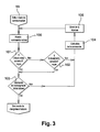
- the figure 3 shows a flowchart that represents a launch of a communication mode for the card 1.
- the beginning 99 of this flow chart begins when the card is placed in the presence of the electromagnetic field. Communication is carried out in accordance with the standard 14443 as long as the communication is desired by the reader or by the card 1. When the communication between the card 1 and the reader is suspended, the reader then continuously transmits "non useful" frames, type R-Block (NAK) or empty I-Block, as mentioned above, in order to detect the presence of the card 1.
- NAK type R-Block
- I-Block empty I-Block
- the card If the card detects a predefined number, for example 5, of "non-useful" consecutive frames, during tests 101 and 102, and that a load is required, during the test 103, then the card 1 switches to a charging mode described by the flowchart of the figure 4 .
- the test 103 is performed by checking during the suspension of a communication if a status bit of the microcontroller 10 has been set to require a charge of the battery.
- the status bit can be activated manually by pressing one of the pushbuttons or automatically, for example when the supply circuit 12 detects a charge level of the battery 19 below a predetermined threshold.
- a power level check step 200 compares the level of the magnetic field with a power level required to determine whether the power received by the electromagnetic field is insufficient, sufficient or more than sufficient.
- an adjustment message sending step 201, 202 or 203 is performed. This adjustment message sending step 201, 202 or 203 corresponds, in the context of the use of the ISO 14443 standard, to the sending of an S-Block (WTX) type message.
- Such a message includes a power level indication parameter, denoted PL (Power Level English) in the standard.
- the power level indication parameter PL can take four distinct values: Binary value Indication 00 Insufficient power for full operation. (Insufficient power for full functionality) 01 Power level indication not supported by the card. (PICC does not support the power level indication) 10 Power sufficient for full operation. (Sufficient power for full functionality) 11 Power more than enough for complete operation. (More than sufficient power for full functionality)
- This parameter is used, normally by the card, to indicate whether the power of the electromagnetic field is sufficient or not to perform a drive command.
- the power required is usually dependent on the type of operation to be performed. For example, writing in a Flash memory, in the card, will require more energy than a reading.
- the power information is used by the card to indicate whether the power of the electromagnetic field is sufficient or not to perform a battery recharge.
- the S-Block (WTX) message also has a WTXM parameter that indicates a waiting time. For adjustment messages, this parameter should be set so that it corresponds to a minimum duration value.
- the card waits for a drive command that must respond with an identical S-Block (WTX) type message to grant the overtime request from the card 1.
- Step 205 checks the type message received. If the message is not S-Block (WTX) then the received message is executed in step 207, a response is returned to the reader in step 208, and the card returns to the communication mode. described by the organization chart of the figure 3 . If the S-Block (WTX) message is received, then it is verified that the field strength is sufficient for charging the battery during a step 206.
- step 200 If the field strength level is not sufficient then return to step 200 to adjust the power level. If the power level is sufficient then a time counter is initialized in step 209 which corresponds to a WTXM overtime request which corresponds to the maximum time value of an S-Block waiting message (WTX). ) sent simultaneously. Then, we cut the power of a large part of the components of the card so that the maximum power is used to recharge the battery and a reloading step 210 is performed.
- WTXM overtime request which corresponds to the maximum time value of an S-Block waiting message (WTX).
- the recharging step 210 is started, a step 211 is performed to check whether the additional time WTXM is expired. If this is the case, we return to step 200 to restart a new request for overtime to the reader. If the extra time WTXM is still running, a step 212 is performed to check whether the battery has finished charging, or if a voluntary cancellation of the recharge has been sent to the microcontroller 10. If the battery has finished charging, then terminate the flowchart by returning the response to the drive command (R-Block (NAK) or empty I-Block depending on the detection mode used). If the battery is not fully charged, then step 210 is looped.
- R-Block NAK
- I-Block empty I-Block depending on the detection mode used
Priority Applications (4)
| Application Number | Priority Date | Filing Date | Title |
|---|---|---|---|
| EP07291480A EP2071497A1 (de) | 2007-12-10 | 2007-12-10 | Verfahren und Vorrichtung zur kontaktlosen Batterieaufladung |
| PCT/EP2008/066075 WO2009074448A1 (en) | 2007-12-10 | 2008-11-24 | Contactless battery charging device and process |
| US12/747,389 US8358104B2 (en) | 2007-12-10 | 2008-11-24 | Contactless battery charging device and process |
| EP08858893.4A EP2232410B1 (de) | 2007-12-10 | 2008-11-24 | Verfahren und vorrichtung zur kontaktlosen batterieaufladung |
Applications Claiming Priority (1)
| Application Number | Priority Date | Filing Date | Title |
|---|---|---|---|
| EP07291480A EP2071497A1 (de) | 2007-12-10 | 2007-12-10 | Verfahren und Vorrichtung zur kontaktlosen Batterieaufladung |
Publications (1)
| Publication Number | Publication Date |
|---|---|
| EP2071497A1 true EP2071497A1 (de) | 2009-06-17 |
Family
ID=39267753
Family Applications (2)
| Application Number | Title | Priority Date | Filing Date |
|---|---|---|---|
| EP07291480A Withdrawn EP2071497A1 (de) | 2007-12-10 | 2007-12-10 | Verfahren und Vorrichtung zur kontaktlosen Batterieaufladung |
| EP08858893.4A Active EP2232410B1 (de) | 2007-12-10 | 2008-11-24 | Verfahren und vorrichtung zur kontaktlosen batterieaufladung |
Family Applications After (1)
| Application Number | Title | Priority Date | Filing Date |
|---|---|---|---|
| EP08858893.4A Active EP2232410B1 (de) | 2007-12-10 | 2008-11-24 | Verfahren und vorrichtung zur kontaktlosen batterieaufladung |
Country Status (3)
| Country | Link |
|---|---|
| US (1) | US8358104B2 (de) |
| EP (2) | EP2071497A1 (de) |
| WO (1) | WO2009074448A1 (de) |
Cited By (2)
| Publication number | Priority date | Publication date | Assignee | Title |
|---|---|---|---|---|
| WO2019175179A1 (en) * | 2018-03-12 | 2019-09-19 | Idex Asa | Device process scheduling |
| WO2021084175A1 (fr) * | 2019-10-31 | 2021-05-06 | Orange | Chargement électrique d'une carte électronique |
Families Citing this family (19)
| Publication number | Priority date | Publication date | Assignee | Title |
|---|---|---|---|---|
| FR2942365A1 (fr) * | 2009-02-13 | 2010-08-20 | St Microelectronics Rousset | Dispositif de communication incluant une batterie et un module de communication a champ proche |
| FR2957440B1 (fr) | 2010-03-09 | 2012-08-17 | Proton World Int Nv | Protection d'un module de securite dans un dispositif de telecommunication couple a un circuit nfc |
| FR2957437B1 (fr) | 2010-03-09 | 2012-03-30 | Proton World Int Nv | Protection contre un deroutement d'un canal de communication d'un circuit nfc |
| FR2957439B1 (fr) | 2010-03-09 | 2012-03-30 | Proton World Int Nv | Protection d'un canal de communication entre un module de securite et un circuit nfc |
| FR2957438B1 (fr) | 2010-03-09 | 2012-03-30 | Proton World Int Nv | Detection d'un deroutement d'un canal de communication d'un dispositif de telecommunication couple a un circuit nfc |
| FR2964285B1 (fr) | 2010-08-31 | 2012-09-07 | Proton World Int Nv | Protection d'un canal de communication d'un dispositif de telecommunication couple a un circuit nfc contre un deroutement |
| FR2964276B1 (fr) * | 2010-08-31 | 2012-09-07 | Proton World Int Nv | Securisation d'un dispositif de telecommunication equipe d'un module de communication en champ proche |
| FR2969341B1 (fr) | 2010-12-20 | 2013-01-18 | Proton World Int Nv | Gestion de canaux de communication dans un dispositif de telecommunication couple a un circuit nfc |
| FR2973901B1 (fr) | 2011-04-05 | 2013-04-19 | Proton World Int Nv | Test de la resistance d'un module de securite d'un dispositif de telecommunication couple a un circuit nfc contre des attaques par detournement de canal de communication |
| FR2974208B1 (fr) | 2011-04-13 | 2013-08-16 | Proton World Int Nv | Mecanisme de controle d'acces pour un element securise couple a un circuit nfc. |
| US9697452B2 (en) | 2012-07-24 | 2017-07-04 | On Track Innovations Ltd. | Adapter for personal electronic devices and methods of use thereof |
| TWI595423B (zh) * | 2012-08-31 | 2017-08-11 | 達意科技股份有限公司 | 電子卡片 |
| US20140159673A1 (en) * | 2012-12-07 | 2014-06-12 | Samsung Electronics Co., Ltd. | Wireless charging apparatus and method |
| US9112543B2 (en) * | 2012-12-27 | 2015-08-18 | Cambridge Silicon Radio Limited | Near field communication devices and methods |
| US9400756B2 (en) | 2014-01-23 | 2016-07-26 | On Track Innovations Ltd. | Adapter for personal electronic devices and methods of use thereof |
| JP6498391B2 (ja) * | 2014-06-25 | 2019-04-10 | ローム株式会社 | モバイル機器およびその制御方法 |
| FR3087283B1 (fr) * | 2018-10-12 | 2020-10-09 | Idemia France Sas | Recharge d'une batterie embarquee dans une carte a puce |
| FR3105629B1 (fr) * | 2019-12-19 | 2023-03-17 | St Microelectronics Rousset | Procédé de gestion d’alimentation |
| GB2621606A (en) * | 2022-08-17 | 2024-02-21 | Freevolt Tech Limited | Device and method |
Citations (9)
| Publication number | Priority date | Publication date | Assignee | Title |
|---|---|---|---|---|
| US6291968B1 (en) * | 2000-05-08 | 2001-09-18 | Lear Corporation | System for automatically charging the battery of a remote transmitter for use in a vehicle security system |
| WO2003091943A1 (en) * | 2002-04-24 | 2003-11-06 | Marconi Intellectual Property (Us) Inc | Energy source recharging device and method |
| US20040001453A1 (en) * | 2002-06-20 | 2004-01-01 | Sanyo Electric Co., Ltd. | Wireless type data transmission device |
| US20060012464A1 (en) * | 2004-07-01 | 2006-01-19 | Zvi Nitzan | Battery-assisted backscatter RFID transponder |
| WO2006085246A1 (en) * | 2005-02-09 | 2006-08-17 | Nxp B.V. | Method for ensuring a secure nfc functionality of a wireless mobile communication device and wireless mobile communication device having a secure nfc functionality |
| WO2006109032A1 (en) * | 2005-04-11 | 2006-10-19 | Innovision Research & Technology Plc | Communications apparatus |
| US7212110B1 (en) * | 2004-04-19 | 2007-05-01 | Advanced Neuromodulation Systems, Inc. | Implantable device and system and method for wireless communication |
| US20070182367A1 (en) * | 2006-01-31 | 2007-08-09 | Afshin Partovi | Inductive power source and charging system |
| WO2007122439A1 (en) * | 2006-04-24 | 2007-11-01 | Nokia Corporation | System and method for manage and control near field communication for a mobile multifunctional device when the device is uncharged or only partially charged |
Family Cites Families (5)
| Publication number | Priority date | Publication date | Assignee | Title |
|---|---|---|---|---|
| US5300875A (en) * | 1992-06-08 | 1994-04-05 | Micron Technology, Inc. | Passive (non-contact) recharging of secondary battery cell(s) powering RFID transponder tags |
| US6788953B1 (en) * | 2000-06-05 | 2004-09-07 | Uniden America Corporation | Wireless local loop communication system using SLIC module |
| US7860680B2 (en) * | 2002-03-07 | 2010-12-28 | Microstrain, Inc. | Robotic system for powering and interrogating sensors |
| DE102004039649A1 (de) * | 2004-08-16 | 2006-03-09 | Giesecke & Devrient Gmbh | Zeitgesteuertes kontaktloses Aufladen eines Akkumulators |
| EP1782330B1 (de) | 2004-08-16 | 2016-12-07 | Giesecke & Devrient GmbH | Gesteuertes kontaktloses aufladen eines akkumulators in einer chipkarte |
-
2007
- 2007-12-10 EP EP07291480A patent/EP2071497A1/de not_active Withdrawn
-
2008
- 2008-11-24 US US12/747,389 patent/US8358104B2/en active Active
- 2008-11-24 EP EP08858893.4A patent/EP2232410B1/de active Active
- 2008-11-24 WO PCT/EP2008/066075 patent/WO2009074448A1/en active Application Filing
Patent Citations (10)
| Publication number | Priority date | Publication date | Assignee | Title |
|---|---|---|---|---|
| US6291968B1 (en) * | 2000-05-08 | 2001-09-18 | Lear Corporation | System for automatically charging the battery of a remote transmitter for use in a vehicle security system |
| WO2003091943A1 (en) * | 2002-04-24 | 2003-11-06 | Marconi Intellectual Property (Us) Inc | Energy source recharging device and method |
| US20040080299A1 (en) * | 2002-04-24 | 2004-04-29 | Forster Ian J. | Energy source recharging device and method |
| US20040001453A1 (en) * | 2002-06-20 | 2004-01-01 | Sanyo Electric Co., Ltd. | Wireless type data transmission device |
| US7212110B1 (en) * | 2004-04-19 | 2007-05-01 | Advanced Neuromodulation Systems, Inc. | Implantable device and system and method for wireless communication |
| US20060012464A1 (en) * | 2004-07-01 | 2006-01-19 | Zvi Nitzan | Battery-assisted backscatter RFID transponder |
| WO2006085246A1 (en) * | 2005-02-09 | 2006-08-17 | Nxp B.V. | Method for ensuring a secure nfc functionality of a wireless mobile communication device and wireless mobile communication device having a secure nfc functionality |
| WO2006109032A1 (en) * | 2005-04-11 | 2006-10-19 | Innovision Research & Technology Plc | Communications apparatus |
| US20070182367A1 (en) * | 2006-01-31 | 2007-08-09 | Afshin Partovi | Inductive power source and charging system |
| WO2007122439A1 (en) * | 2006-04-24 | 2007-11-01 | Nokia Corporation | System and method for manage and control near field communication for a mobile multifunctional device when the device is uncharged or only partially charged |
Cited By (5)
| Publication number | Priority date | Publication date | Assignee | Title |
|---|---|---|---|---|
| WO2019175179A1 (en) * | 2018-03-12 | 2019-09-19 | Idex Asa | Device process scheduling |
| EP4030345A1 (de) * | 2018-03-12 | 2022-07-20 | Idex Biometrics Asa | Zeitplanung für vorrichtungsprozess |
| US11687482B2 (en) | 2018-03-12 | 2023-06-27 | Idex Biometrics Asa | Device process scheduling |
| WO2021084175A1 (fr) * | 2019-10-31 | 2021-05-06 | Orange | Chargement électrique d'une carte électronique |
| FR3104352A1 (fr) * | 2019-10-31 | 2021-06-11 | Orange | Chargement électrique d’une carte électronique |
Also Published As
| Publication number | Publication date |
|---|---|
| EP2232410B1 (de) | 2019-01-02 |
| WO2009074448A1 (en) | 2009-06-18 |
| US8358104B2 (en) | 2013-01-22 |
| US20100259216A1 (en) | 2010-10-14 |
| EP2232410A1 (de) | 2010-09-29 |
Similar Documents
| Publication | Publication Date | Title |
|---|---|---|
| EP2071497A1 (de) | Verfahren und Vorrichtung zur kontaktlosen Batterieaufladung | |
| EP0565469B1 (de) | System zum kontaktlosen Austausch von Daten zwischen einem Endgerät und einer modularen, tragbaren Einheit | |
| EP1938242B1 (de) | Nfc-lesegerät mit passivem betriebsmodus mit geringem energieverbrauch | |
| EP2219353B1 (de) | Mobiltelefon mit Batterie und einem Nahfeldkommunikationsmodul | |
| EP2341469B1 (de) | Elektronisches System und Verfahren zum Management von konkurrierenden kontaktlosen Kommunikationen im System | |
| EP1851865B1 (de) | Verfahren zur sicherstellung einer sicheren nfc-funktionalität einer drahtlosen mobilen kommunikationsvorrichtung und drahtlose mobile kommunikationsvorrichtung mit sicherer nfc-funktionalität | |
| EP2131313A1 (de) | Verfahren zur Anwendungsauswahl in einem drahtlosen mobilen Kommunikationsgerät in einem NFC-System und entsprechendes drahtloses mobiles Kommunikationsgerät | |
| US20140065961A1 (en) | Communications device for intelligently routing information among multiple user interfaces | |
| EP3794538A1 (de) | Autonomes registrierungssystem und -verfahren für den eigentümer einer biometrischen vorrichtung | |
| EP0917684A1 (de) | Mikroschaltung mit gemischter kontaktlosen oder kontaktierenden funktionalität | |
| EP2230774B1 (de) | Verfahren zur Herstellung einer Datenverbindung zwischen zwei Prozessoren, insbesondere in einem NFC-Chipset | |
| EP2114019B1 (de) | Wiederaufladung eines aktiven Transponders | |
| EP1496470B1 (de) | Kombi-Chipkarte | |
| EP2070018B1 (de) | An einem zu identifizierenden objekt befestigtes rfid | |
| EP3001575A1 (de) | Verfahren zur steuerung des betriebs eines objekts, das in der lage ist, ohne einen kontakt mit einem lesegerät zu kommunizieren, entsprechende vorrichtung und entsprechendes objekt | |
| FR2851382A1 (fr) | Systeme a module de communication bluetooth a alimentation commandee, ensemble de radiocommunication, procedes et lecteurs | |
| CN105322602A (zh) | 电子设备及电子设备的控制方法 | |
| FR2864297A1 (fr) | Information pleinement simultanee de variations de status pour un objet a interface duale | |
| EP2582113A1 (de) | Adaptationsvorrichtung zwischen einem kontaktlosen Lesegerät und einem Funkgerät | |
| FR2943818A1 (fr) | Procede et dispositif permettant de selectionner automatiquement une application pouvant etre mise en oeuvre par ce dispositif | |
| WO2011151366A1 (fr) | Carte bancaire avec ecran d'affichage | |
| FR2864296A1 (fr) | Immunite aux variations de ressources limitees, fournies a un objet a interface duale | |
| EP3214582B1 (de) | Auswahl von apps in einem mobilen endgerät | |
| EP2372613A1 (de) | Funkkommunikationsgegenstand mit doppelter Reichweite, und Umsetzungsverfahren | |
| EP4052391A1 (de) | Elektrische aufladung einer leiterplatte |
Legal Events
| Date | Code | Title | Description |
|---|---|---|---|
| PUAI | Public reference made under article 153(3) epc to a published international application that has entered the european phase |
Free format text: ORIGINAL CODE: 0009012 |
|
| AK | Designated contracting states |
Kind code of ref document: A1 Designated state(s): AT BE BG CH CY CZ DE DK EE ES FI FR GB GR HU IE IS IT LI LT LU LV MC MT NL PL PT RO SE SI SK TR |
|
| AX | Request for extension of the european patent |
Extension state: AL BA HR MK RS |
|
| AKX | Designation fees paid | ||
| REG | Reference to a national code |
Ref country code: DE Ref legal event code: 8566 |
|
| STAA | Information on the status of an ep patent application or granted ep patent |
Free format text: STATUS: THE APPLICATION IS DEEMED TO BE WITHDRAWN |
|
| 18D | Application deemed to be withdrawn |
Effective date: 20091218 |