EP2071245A2 - Heating system - Google Patents
Heating system Download PDFInfo
- Publication number
- EP2071245A2 EP2071245A2 EP08021435A EP08021435A EP2071245A2 EP 2071245 A2 EP2071245 A2 EP 2071245A2 EP 08021435 A EP08021435 A EP 08021435A EP 08021435 A EP08021435 A EP 08021435A EP 2071245 A2 EP2071245 A2 EP 2071245A2
- Authority
- EP
- European Patent Office
- Prior art keywords
- heat
- control unit
- central control
- heating system
- heat generator
- Prior art date
- Legal status (The legal status is an assumption and is not a legal conclusion. Google has not performed a legal analysis and makes no representation as to the accuracy of the status listed.)
- Withdrawn
Links
- 238000010438 heat treatment Methods 0.000 title claims description 28
- 238000000034 method Methods 0.000 claims abstract description 9
- 238000010586 diagram Methods 0.000 claims description 7
- 230000003993 interaction Effects 0.000 claims description 6
- 238000009434 installation Methods 0.000 claims 1
- 238000005338 heat storage Methods 0.000 description 7
- 238000009420 retrofitting Methods 0.000 description 3
- XLYOFNOQVPJJNP-UHFFFAOYSA-N water Substances O XLYOFNOQVPJJNP-UHFFFAOYSA-N 0.000 description 3
- 230000001419 dependent effect Effects 0.000 description 2
- 238000011161 development Methods 0.000 description 2
- 230000018109 developmental process Effects 0.000 description 2
- 238000004891 communication Methods 0.000 description 1
Images
Classifications
-
- F—MECHANICAL ENGINEERING; LIGHTING; HEATING; WEAPONS; BLASTING
- F24—HEATING; RANGES; VENTILATING
- F24D—DOMESTIC- OR SPACE-HEATING SYSTEMS, e.g. CENTRAL HEATING SYSTEMS; DOMESTIC HOT-WATER SUPPLY SYSTEMS; ELEMENTS OR COMPONENTS THEREFOR
- F24D12/00—Other central heating systems
- F24D12/02—Other central heating systems having more than one heat source
-
- F—MECHANICAL ENGINEERING; LIGHTING; HEATING; WEAPONS; BLASTING
- F24—HEATING; RANGES; VENTILATING
- F24D—DOMESTIC- OR SPACE-HEATING SYSTEMS, e.g. CENTRAL HEATING SYSTEMS; DOMESTIC HOT-WATER SUPPLY SYSTEMS; ELEMENTS OR COMPONENTS THEREFOR
- F24D19/00—Details
- F24D19/10—Arrangement or mounting of control or safety devices
- F24D19/1006—Arrangement or mounting of control or safety devices for water heating systems
- F24D19/1009—Arrangement or mounting of control or safety devices for water heating systems for central heating
-
- F—MECHANICAL ENGINEERING; LIGHTING; HEATING; WEAPONS; BLASTING
- F24—HEATING; RANGES; VENTILATING
- F24D—DOMESTIC- OR SPACE-HEATING SYSTEMS, e.g. CENTRAL HEATING SYSTEMS; DOMESTIC HOT-WATER SUPPLY SYSTEMS; ELEMENTS OR COMPONENTS THEREFOR
- F24D2200/00—Heat sources or energy sources
- F24D2200/04—Gas or oil fired boiler
-
- F—MECHANICAL ENGINEERING; LIGHTING; HEATING; WEAPONS; BLASTING
- F24—HEATING; RANGES; VENTILATING
- F24D—DOMESTIC- OR SPACE-HEATING SYSTEMS, e.g. CENTRAL HEATING SYSTEMS; DOMESTIC HOT-WATER SUPPLY SYSTEMS; ELEMENTS OR COMPONENTS THEREFOR
- F24D2200/00—Heat sources or energy sources
- F24D2200/12—Heat pump
-
- F—MECHANICAL ENGINEERING; LIGHTING; HEATING; WEAPONS; BLASTING
- F24—HEATING; RANGES; VENTILATING
- F24D—DOMESTIC- OR SPACE-HEATING SYSTEMS, e.g. CENTRAL HEATING SYSTEMS; DOMESTIC HOT-WATER SUPPLY SYSTEMS; ELEMENTS OR COMPONENTS THEREFOR
- F24D2200/00—Heat sources or energy sources
- F24D2200/14—Solar energy
-
- Y—GENERAL TAGGING OF NEW TECHNOLOGICAL DEVELOPMENTS; GENERAL TAGGING OF CROSS-SECTIONAL TECHNOLOGIES SPANNING OVER SEVERAL SECTIONS OF THE IPC; TECHNICAL SUBJECTS COVERED BY FORMER USPC CROSS-REFERENCE ART COLLECTIONS [XRACs] AND DIGESTS
- Y02—TECHNOLOGIES OR APPLICATIONS FOR MITIGATION OR ADAPTATION AGAINST CLIMATE CHANGE
- Y02B—CLIMATE CHANGE MITIGATION TECHNOLOGIES RELATED TO BUILDINGS, e.g. HOUSING, HOUSE APPLIANCES OR RELATED END-USER APPLICATIONS
- Y02B10/00—Integration of renewable energy sources in buildings
- Y02B10/20—Solar thermal
-
- Y—GENERAL TAGGING OF NEW TECHNOLOGICAL DEVELOPMENTS; GENERAL TAGGING OF CROSS-SECTIONAL TECHNOLOGIES SPANNING OVER SEVERAL SECTIONS OF THE IPC; TECHNICAL SUBJECTS COVERED BY FORMER USPC CROSS-REFERENCE ART COLLECTIONS [XRACs] AND DIGESTS
- Y02—TECHNOLOGIES OR APPLICATIONS FOR MITIGATION OR ADAPTATION AGAINST CLIMATE CHANGE
- Y02B—CLIMATE CHANGE MITIGATION TECHNOLOGIES RELATED TO BUILDINGS, e.g. HOUSING, HOUSE APPLIANCES OR RELATED END-USER APPLICATIONS
- Y02B10/00—Integration of renewable energy sources in buildings
- Y02B10/70—Hybrid systems, e.g. uninterruptible or back-up power supplies integrating renewable energies
-
- Y—GENERAL TAGGING OF NEW TECHNOLOGICAL DEVELOPMENTS; GENERAL TAGGING OF CROSS-SECTIONAL TECHNOLOGIES SPANNING OVER SEVERAL SECTIONS OF THE IPC; TECHNICAL SUBJECTS COVERED BY FORMER USPC CROSS-REFERENCE ART COLLECTIONS [XRACs] AND DIGESTS
- Y02—TECHNOLOGIES OR APPLICATIONS FOR MITIGATION OR ADAPTATION AGAINST CLIMATE CHANGE
- Y02B—CLIMATE CHANGE MITIGATION TECHNOLOGIES RELATED TO BUILDINGS, e.g. HOUSING, HOUSE APPLIANCES OR RELATED END-USER APPLICATIONS
- Y02B30/00—Energy efficient heating, ventilation or air conditioning [HVAC]
Definitions
- the invention relates to a heating system according to the preamble of patent claim 1.
- a heating system of the type mentioned is known per se. It consists of at least two heat generators (for example: boiler, solar system, heat pump, etc.) and typically a heat storage (usually a hot water tank), the heat generator each having at least one switching unit for controlling heat generator internal processes (ie an electrical or electronic circuit responsible for linking together the internal components of the heat generator), each switching unit having a higher-level central control unit (known, for example, the Applotronic Vitotronic® 333 cascade control housed in its own control housing) for coordinating the hydraulic interaction, in particular of the heat generators , but also the heat accumulator is connected, wherein the central control unit is designed for initial storage of a hydraulic circuit diagram of the heat generator and optionally the heat accumulator, d. H.
- the central control unit is designed for initial storage of a hydraulic circuit diagram of the heat generator and optionally the heat accumulator, d. H.
- commissioning the heating system of the central control unit is informed by the operator how the heat generator and heat storage are hydraulically linked together, so
- the invention has for its object to produce a heating system of the type mentioned cost and offer.
- At least one of the heat generators has the central control unit as an integral part.
- the central control unit is integrated in at least one of the heat generator, so that a separate housing is dispensable.
- this requirement has a further significant advantage, which can be seen by considering the case study of retrofitting existing existing plants:
- a central control unit is then integrated into a heat pump to be retrofitted, then after the operator, who is guided via a suitable input menu, has stored the concrete hydraulic circuit diagram in it, he can take complete control of the entire heating system, without It would be necessary to provide an overall higher-level, separately installed central control unit such as the Vitotronic® 333.
- the heat generators are ultimately simply connected to one another via a standard interface and operated by a kind of standardized network cable. If there are several central control units (for example, because both a heat pump and a solar system with central control unit has been retrofitted), one is defined as the decisive and the other switched off or simply ignored.
- the purchase of a arranged in a separate housing central control unit is eliminated, which obviously significantly reduces the cost of retrofitting an existing heating system.
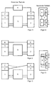
- FIG. 1 First, a known according to the prior art heating system is shown. This consists of two heat generators 1, 2 (for example, a gas boiler and a heat pump), each having a switching unit 3 for controlling heat generator internal processes.
- each heat generator 1, 2 a single control unit 7, which serves to control the individual heat generator 1, 2.
- This single control unit 7 is in close contact with the switching unit 3 (for example, the automatic burner control of a boiler), which, as mentioned, not for control, but only for electrical connection of the individual components of the heat generator 1, 2 is used.
- Each individual control unit 7 is equipped with software that is tailored to the characteristics of the respective heat generator 1, 2.
- the software of the individual control unit 7 of the one heat generator 1 does not know the characteristics of the other heat generator 2, that is to say it is in each case heat generator-specific software, which is stored in each case in a main processor.
- each switching unit 3 is connected (via the individual control unit 7) to a higher-level central control unit 4 (for coordinating the hydraulic interaction) of the heat generators 1, 2.
- the central control unit 4 for initial storage of a hydraulic circuit diagram of the heat generator 1, 2 is formed.
- these two heating systems also have two heat generators 1, 2, each having a switching unit 3 for controlling heat-generator-internal processes, each switching unit 3 having a higher-level central control unit 4 for coordinating the hydraulic interaction of the heat generators 1, 2, wherein the central control unit 4 for initial storage of a hydraulic circuit diagram of the heat generator 1, 2 is formed.
- Both heat generators 1, 2 have such a central control unit 4.
- it is thus typically a heating system, which is constructed from heat generators 1, 2 according to the invention with central control unit 4.
- one of the two central control units 4 takes over control of the entire system in the illustrated case, while the other central control unit 4 ultimately only serves to forward the information from the switching unit 3 on.
- FIG. 3 shows the typical situation when retrofitting an existing old heating system.
- the heat generator 1 for example, a boiler
- the heat generator 2 for example, a heat pump or a solar system, but also another boiler is possible [cascade solution]
- this invention comprises not only a single control unit 7, but a higher-level central control unit 4, this retrofitted device can directly take over the control of the entire system.
- the central control unit 4 only with the heat generator 1 or the switching unit 3 or (shown in phantom) to be connected to the single control unit 7.
- FIGS. 1 to 3 there is the one in the FIGS. 1 to 3 illustrated, known per se heat storage 5 to explain.
- These are, for example, a so-called bivalent hot water tank, to which heat can be supplied via the two heat generators 1, 2. Since often the interconnection of the heating system is not so simple, as shown, is formed, it is particularly preferably provided that the central control unit 4 for coordinating the hydraulic interaction and preferably for initial storage of a hydraulic circuit diagram of both the heat generator 1, 2 and the heat accumulator 5 is formed ,
- FIG. 4 a central control unit 4 according to the known, prior art explained.
- This has a plurality of (here for simplicity only shown two) interfaces 6 for connection of optional switching 3 and / or individual control units 7.
- Each interface 6 is associated with a processor 8, are stored on the heat generator specific characteristics.
- the processors 8 themselves are also interconnected to allow control of the overall system.
- inventive embodiment of the central control unit 4 is after FIG. 5 and in contrast to the usual solution after FIG. 4 provided that the central control unit 4 has a with all interfaces 4 at least in phases connected main processor 8. According to the invention thus becomes a slightly larger main processor 8 is provided, but overall is less expensive than several, smaller main processors 8 (see FIG. 4 ).
- the main processor 8 is a different characteristics of heat generators 1, 2 stored software is stored, which is particularly preferably provided that the various characteristics are stored in layers in the main processor 8 and retrievable.
- the software stored in the main processor 8 consists of at least two modules, wherein the first module is designed to take over general, heat generator-specific control functions and the second module for receiving and executing several, heat generator specific characteristics.
- a third module for receiving and execution of heat consumer specific characteristics may be provided.
- FIG. 4 requires the main processor 8 according to FIG. 5 namely not just the X-fold amount of storage space (where X is the number of main processor 8 in FIG.
Abstract
Description
Die Erfindung betrifft eine Heizungsanlage gemäß dem Oberbegriff des Patentanspruchs 1.The invention relates to a heating system according to the preamble of
Eine Heizungsanlage der eingangs genannten Art ist an sich bekannt. Sie besteht aus mindestens zwei Wärmeerzeugern (zum Beispiel: Heizkessel, Solaranlage, Wärmepumpe etc.) und typischerweise einem Wärmespeicher (in der Regel ein Warmwasserspeicher), wobei die Wärmeerzeuger jeweils mindestens eine Schalteinheit zur Steuerung wärmeerzeugerinterner Abläufe aufweisen (also eine elektrische bzw. elektronische Schaltung, die dafür verantwortlich ist, die internen Komponenten des Wärmeerzeugers miteinander zu verknüpfen), wobei jede Schalteinheit mit einer übergeordneten Zentralregeleinheit (bekannt ist hier zum Beispiel die in einem eigenen Regelungsgehäuse untergebrachte Kaskadenregelung Vitotronic® 333 der Anmelderin) zur Koordination des hydraulischen Zusammenwirkens insbesondere der Wärmeerzeuger, aber auch des Wärmespeichers verbunden ist, wobei die Zentralregeleinheit zur initialen Abspeicherung eines Hydraulikverschaltungsplans der Wärmeerzeuger und gegebenenfalls des Wärmespeichers ausgebildet ist, d. h. insbesondere bei Inbetriebnahme der Heizungsanlage wird der Zentralregeleinheit vom Betreiber mitgeteilt, wie die Wärmeerzeuger und Wärmespeicher hydraulisch miteinander verknüft sind, wie sie also miteinander zusammenarbeiten können.A heating system of the type mentioned is known per se. It consists of at least two heat generators (for example: boiler, solar system, heat pump, etc.) and typically a heat storage (usually a hot water tank), the heat generator each having at least one switching unit for controlling heat generator internal processes (ie an electrical or electronic circuit responsible for linking together the internal components of the heat generator), each switching unit having a higher-level central control unit (known, for example, the Applotronic Vitotronic® 333 cascade control housed in its own control housing) for coordinating the hydraulic interaction, in particular of the heat generators , but also the heat accumulator is connected, wherein the central control unit is designed for initial storage of a hydraulic circuit diagram of the heat generator and optionally the heat accumulator, d. H. In particular, when commissioning the heating system of the central control unit is informed by the operator how the heat generator and heat storage are hydraulically linked together, so how they can work together.
Der Erfindung liegt die Aufgabe zugrunde, eine Heizungsanlage der eingangs genannten Art kostengünstiger herstellen und anbieten zu können.The invention has for its object to produce a heating system of the type mentioned cost and offer.
Diese Aufgabe ist mit einer Heizungsanlage der eingangs genannten Art durch die im Kennzeichen des Patentanspruchs 1 aufgeführten Merkmale gelöst.This object is achieved with a heating system of the type mentioned by the features listed in the characterizing part of
Nach der Erfindung ist also vorgesehen, dass mindestens einer der Wärmeerzeuger die Zentralregeleinheit als integralen Bestandteil aufweist.According to the invention, it is thus provided that at least one of the heat generators has the central control unit as an integral part.
Mit anderen Worten ausgedrückt, wird die Zentralregeleinheit in mindestens einen der Wärmeerzeuger integriert, so dass ein separates Gehäuse verzichtbar ist. Darüber hinaus, und das ist noch wesentlicher, hat diese Maßgabe einen weiteren erheblichen Vorteil, der sich erschließt, wenn man das Fallbeispiel der Nachrüstung von bestehenden Altanlagen betrachtet:In other words, the central control unit is integrated in at least one of the heat generator, so that a separate housing is dispensable. In addition, and more importantly, this requirement has a further significant advantage, which can be seen by considering the case study of retrofitting existing existing plants:
Unterstellt man eine typische Ausgangssituation, bei der in einem Gebäude ein Heizkessel und ein Wärmespeicher untergebracht sind und soll diese Anlage nun zum Beispiel um eine Wärmepumpe und/oder eine Solaranlage ergänzt werden, so besteht die bisher übliche Vorgehensweise darin, eine Wärmepumpe und/oder eine Solaranlage zu beschaffen, die neben der Schalteinheit zur Steuerung wärmeerzeugerinterner Abläufe stets auch eine eigene Zentralregeleinheit umfasst, die mit der Zentralregeleinheit des Heizkessels kommuniziert. Problematisch an dieser Kommunikation ist allerdings, dass damit letztlich zwei (oder sogar drei) Zentralregeleinheiten vorhanden sind, die zudem, weil sie hierfür auch nicht ausgelegt sind, nicht zur gegenseitigen Abstimmung ihres Regelungsverhaltens in der Lage sind. So hat zum Beispiel der Regler des Heizkessels höchstens über den Wärmespeicher Informationskontakt zum Regler der Solaranlage, aber eben keinen echten Einfluss auf dessen Regelverhalten. Je nach hydraulischer Schaltung kann es sogar sein, dass bei den bisher üblichen Regelungs- und Verschaltungskonzepten ein Heizkessel einen vorhandenen Wärmespeicher nicht aufladen kann, weil hierfür ausschließlich die nachgerüstete Wärmepumpe zuständig ist.Assuming a typical situation in which a boiler and a heat storage are housed in a building and this system is now for example to be supplemented by a heat pump and / or a solar system, so far the usual procedure is a heat pump and / or a To procure solar system, which in addition to the switching unit for controlling heat generator internal processes always includes its own central control unit that communicates with the central control unit of the boiler. The problem with this communication, however, is that ultimately two (or even three) central control units are present, which, moreover, because they are not designed for this purpose, are not capable of coordinating their control behavior. For example, the controller of the boiler has at most the information about the controller of the solar system through the heat storage, but just no real impact on its control behavior. Depending on the hydraulic circuit, it may even be that in the usual control and Verschaltungskonzepten a boiler can not charge an existing heat storage, because this is only the retrofitted heat pump is responsible.
Integriert man nun eine Zentralregeleinheit zum Beispiel in eine nachzurüstende Wärmepumpe, so kann diese, nachdem der Betreiber, der über ein geeignetes Eingabemenü geführt wird, den konkreten Hydraulikverschaltungsplan in ihr abgespeichert hat, die vollständige Kontrolle über die gesamte Heizungsanlage übernehmen, und zwar ohne, dass es erforderlich wäre, eine insgesamt übergeordnete, separat zu installierende Zentralregeleinheit wie die Vitotronic® 333 vorzusehen.If, for example, a central control unit is then integrated into a heat pump to be retrofitted, then after the operator, who is guided via a suitable input menu, has stored the concrete hydraulic circuit diagram in it, he can take complete control of the entire heating system, without It would be necessary to provide an overall higher-level, separately installed central control unit such as the Vitotronic® 333.
Da eine solche Zentralregeleinheit letztlich aus wenigen elektronischen Bauteilen, vorallem aber aus Software besteht, ist darüber hinaus vorteilhaft vorgesehen, stets bei allen neuen Wärmeerzeugern (also Heizkesseln, Wärmepumpen, Solaranlagen usw.) eine solche Zentralregeleinheit zu integrieren, da es auf diese Weise möglich ist, lediglich durch Nachkauf des nachzurüstenden Wärmeerzeugers auch gleich die für die neu entstehende Gesamtanlage erforderlich Regelung bereit zu stellen.Since such a central control unit ultimately consists of a few electronic components, but above all of software, is also advantageously provided always with all new heat generators (ie boilers, heat pumps, solar systems, etc.) to integrate such a central control unit, since it is possible in this way , just by the purchase of the retrofitted heat generator also equal to provide the required for the new overall system control ready.
Dabei werden die Wärmeerzeuger letztlich einfach durch eine Art standardisiertes Netzwerkkabel miteinander über eine Standardschnittstelle verbunden und betrieben. Sollte es dabei zufällig mehrere Zentralregeleinheiten geben (zum Beispiel, weil sowohl eine Wärmepumpe als auch eine Solaranlage mit Zentralregeleinheit nachgerüstet wurde), wird eine als die entscheidende definiert und die übrigen abgeschaltet bzw. einfach ignoriert. Es entsteht auf diese Weise eine Heizungsanlage mit Wärmeerzeugern, bei denen letztlich die Schalteinheiten zur Steuerung wärmeerzeugerinterner Abläufe über Netzwerkverbindungen mit einer in einem der Wärmeerzeuger angeordneten Zentralregeleinheit verbunden sind. Der Kauf einer in einem separaten Gehäuse angeordneten Zentralregeleinheit entfällt, was offensichtlich die Kosten für die Nachrüstung einer bestehenden Heizungsanlage erheblich senkt.In the process, the heat generators are ultimately simply connected to one another via a standard interface and operated by a kind of standardized network cable. If there are several central control units (for example, because both a heat pump and a solar system with central control unit has been retrofitted), one is defined as the decisive and the other switched off or simply ignored. This creates a heating system with heat generators, in which ultimately the switching units for controlling heat-generator-internal processes via network connections are connected to a arranged in one of the heat generator central control unit. The purchase of a arranged in a separate housing central control unit is eliminated, which obviously significantly reduces the cost of retrofitting an existing heating system.
Andere vorteilhafte Weiterbildungen der erfindungsgemäßen Heizungsanlage ergeben sich aus den abhängigen Patentansprüchen.Other advantageous developments of the heating system according to the invention will become apparent from the dependent claims.
Die erfindungsgemäße Heizungsanlage einschließlich ihrer vorteilhaften Weiterbildungen gemäß der abhängigen Patentansprüche wird nachfolgend anhand der zeichnerischen Darstellung verschiedener Ausführungsbeispiele näher erläutert.The heating system according to the invention including its advantageous developments according to the dependent claims will be explained in more detail with reference to the drawings of various embodiments.
Es zeigt schematisch
Figur 1- eine Heizungsanlage gemäß dem vorbeschriebenen Stand der Technik;
Figur 2- die erfindungsgemäße Heizungsanlage mit zwei Wärme- erzeugern, die jeweils eine übergeordnete Zentral- regeleinheit aufweisen;
Figur 3- die erfindungsgemäße Heizungsanlage mit einem Wär- meerzeuger, der eine Einzelregeleinheit aufweist, und einen nachgerüsteten Wärmeerzeuger, der eine übergeordnete Zentralregeleinheit umfasst;
Figur 4- eine Zentralregeleinheit gemäß dem Stand der Tech- nik mit zwei Hauptprozessoren; und
Figur 5- eine erfindungsgemäße Zentralregeleinheit mit einem einzigen Hauptprozessor.
- FIG. 1
- a heating system according to the above-described prior art;
- FIG. 2
- the heating system according to the invention with two heat generators, each having a higher-level central control unit;
- FIG. 3
- the heating system according to the invention with a heat generator, which has a single control unit, and a retrofitted heat generator comprising a higher-level central control unit;
- FIG. 4
- a central control unit according to the prior art with two main processors; and
- FIG. 5
- a central control unit according to the invention with a single main processor.
In
Um die beiden Wärmeerzeuger 1, 2 miteinander zu verknüpfen, ist nach bekanntem Stand der Technik jede Schalteinheit 3 (über die Einzelregeleinheit 7) mit einer übergeordneten Zentralregeleinheit 4 (zur Koordination des hydraulischen Zusammenwirkens) der Wärmeerzeuger 1, 2 verbunden ist. Darüber hinaus ist die Zentralregeleinheit 4 zur initialen Abspeicherung eines Hydraulikverschaltungsplans der Wärmeerzeuger 1, 2 ausgebildet.In order to link the two
Mit Verweis auf die beiden erfindungsgemäßen Ausführungsformen gemäß den
Für jede beliebige Ausführungsform der erfindungsgemäße Heizungsanlage ist nun zum Beispiel mit Verweis auf
In
Erfindungsgemäß kann also eine zusätzliche, in einem separaten Gehäuse angeordnete Zentralregeleinheit 4 entfallen, wobei auf weitere Vorteile der erfindungsgemäßen Zentralregeleinheit 4 weiter unten noch genauer eingegangen wird.According to the invention, therefore, an additional, arranged in a separate housing
Zunächst ist noch der in den
Weiterhin zeigt
Gemäß einer besonders bevorzugten, erfindungsgemäßen Ausführungsform der Zentralregeleinheit 4 ist nach
In diesen Hauptprozessor 8 ist dabei eine verschiedene Charakteristiken von Wärmeerzeugern 1, 2 berücksichtigende Software gespeichert, wobei insbesondere bevorzugt vorgesehen ist, dass die verschiedenen Charakteristiken schichtartig im Hauptprozessor 8 gespeichert und abrufbar sind. Der besondere Vorteil dieser Lösung wird weiterhin durch die Maßgabe deutlich, dass die im Hauptprozessor 8 gespeicherte Software aus mindestens zwei Modulen besteht, wobei das erste Modul zur Übernahme allgemeiner, wärmeerzeugerunspezifischer Regelungsfunktionen und das zweite Modul zur Aufnahme und Ausführung mehrerer, wärmeerzeugerspezifische Charakteristiken ausgebildet ist. Ferner kann auch noch ein drittes Modul zur Aufnahme und Ausführung wärmeverbraucherspezifischer Charakteristiken (Warmwasserspeicher, Heizkreis etc.) vorgesehen sein. Im Unterschied zur Lösung nach
- 11
- Wärmeerzeugerheat generator
- 22
- Wärmeerzeugerheat generator
- 33
- Schalteinheitswitching unit
- 44
- ZentralregeleinheitCentral control unit
- 55
- Wärmespeicherheat storage
- 66
- Schnittstelleninterfaces
- 77
- EinzelregeleinheitSingle control unit
- 88th
- Hauptprozessormain processor
Claims (7)
dadurch gekennzeichnet,
dass mindestens einer der Wärmeerzeuger (1, 2) die Zentralregeleinheit (4) als integralen Bestandteil aufweist.Heating system, comprising at least two heat generators (1, 2), each having at least one switching unit (3) for controlling heat generator internal processes, each switching unit (3) with a parent central control unit (4) for coordinating the hydraulic interaction of the heat generator (1, 2 ), wherein the central control unit (4) is designed for the initial storage of a hydraulic circuit diagram of the heat generators (1, 2),
characterized,
in that at least one of the heat generators (1, 2) has the central control unit (4) as an integral component.
dadurch gekennzeichnet,
dass die Zentralregeleinheit (4) zur Koordination des hydraulischen Zusammenwirkens und vorzugsweise zur initialen Abspeicherung eines Hydraulikverschaltungsplans der Wärmeerzeuger (1, 2) und des Wärmespeichers (5) ausgebildet ist.Heating system with at least one heat accumulator (5) according to claim 1,
characterized,
in that the central control unit (4) is designed to coordinate the hydraulic interaction and preferably to initially store a hydraulic circuit diagram of the heat generators (1, 2) and the heat accumulator (5).
dadurch gekennzeichnet,
dass die Zentralregeleinheit (4) einen mit allen Schnittstellen (6) mindestens phasenweise verbundenen Hauptprozessor (8) aufweist.Heating installation according to claim 1 or 2, wherein the central control unit (4) has a plurality of interfaces (6) for connection of optionally switching (3) and / or individual control units (7),
characterized,
that the central control unit (4) has a with all the interfaces (6) at least phasewise main processor (8) connected.
dadurch gekennzeichnet,
dass im Hauptprozessor (8) eine verschiedene Charakteristiken von Wärmeerzeugern (1, 2) berücksichtigende Software gespeichert ist.Heating system according to claim 3,
characterized,
that in the main processor (8) a different characteristics of heat generators (1, 2) considering software is stored.
dadurch gekennzeichnet,
dass die verschiedenen Charakteristiken schichtartig im Hauptprozessor (8) gespeichert und abrufbar sind.Heating system according to claim 4,
characterized,
that the various characteristics are stored in layers in the main processor (8) and retrievable.
dadurch gekennzeichnet,
dass die im Hauptprozessor (8) gespeicherte Software aus mindestens zwei Modulen besteht, wobei das erste Modul zur Übernahme allgemeiner, wärmeerzeugerunspezifischer Regelungsfunktionen und das zweite Modul zur Aufnahme und Ausführung mehrerer, wärmeerzeugerspezifische Charakteristiken ausgebildet ist.Heating system according to claim 4 or 5,
characterized,
in that the software stored in the main processor (8) consists of at least two modules, the first module being designed to take over general heat generator-specific control functions and the second module to receive and execute a plurality of heat generator-specific characteristics.
dadurch gekennzeichnet,
dass ein drittes Modul zur Aufnahme und Ausführung wärmeverbraucherspezifischer Charakteristiken ausgebildet ist.Heating system according to claim 6,
characterized,
that a third module is configured to receive and execute the heat consumer specific characteristics.
Applications Claiming Priority (1)
| Application Number | Priority Date | Filing Date | Title |
|---|---|---|---|
| DE102007061415A DE102007061415A1 (en) | 2007-12-16 | 2007-12-16 | heating system |
Publications (2)
| Publication Number | Publication Date |
|---|---|
| EP2071245A2 true EP2071245A2 (en) | 2009-06-17 |
| EP2071245A3 EP2071245A3 (en) | 2012-08-15 |
Family
ID=40445624
Family Applications (1)
| Application Number | Title | Priority Date | Filing Date |
|---|---|---|---|
| EP08021435A Withdrawn EP2071245A3 (en) | 2007-12-16 | 2008-12-10 | Heating system |
Country Status (2)
| Country | Link |
|---|---|
| EP (1) | EP2071245A3 (en) |
| DE (1) | DE102007061415A1 (en) |
Cited By (1)
| Publication number | Priority date | Publication date | Assignee | Title |
|---|---|---|---|---|
| RU2474770C2 (en) * | 2011-03-30 | 2013-02-10 | Государственное научное учреждение Всероссийский научно-исследовательский технологический институт ремонта и эксплуатации машинно-тракторного парка Российской академии сельскохозяйственных наук (ГНУ ГОСНИТИ РОССЕЛЬХОЗАКАДЕМИИ) | Heat exchange system, using heat pumps (versions) |
Families Citing this family (3)
| Publication number | Priority date | Publication date | Assignee | Title |
|---|---|---|---|---|
| DE102016205033A1 (en) * | 2016-03-24 | 2017-09-28 | Viessmann Werke Gmbh & Co Kg | Device and method for configuring a multivalent power supply system |
| DE102016205036B4 (en) * | 2016-03-24 | 2018-12-13 | Viessmann Werke Gmbh & Co Kg | Method for controlling a power supply system |
| DE102016205028A1 (en) | 2016-03-24 | 2017-09-28 | Viessmann Werke Gmbh & Co Kg | Method for controlling a multivalent power supply system |
Family Cites Families (6)
| Publication number | Priority date | Publication date | Assignee | Title |
|---|---|---|---|---|
| US4627483A (en) * | 1984-01-09 | 1986-12-09 | Visual Information Institute, Inc. | Heat pump control system |
| EP0445310A1 (en) * | 1990-02-09 | 1991-09-11 | Viessmann Werke GmbH & Co. | Method and device for in-temperature regulation of a multi-boiler heating system |
| DE19816165B4 (en) * | 1998-04-09 | 2006-02-23 | Viessmann Werke Gmbh & Co Kg | Method and device for commissioning a heating system |
| DE29812549U1 (en) * | 1998-07-14 | 1998-10-08 | Viessmann Werke Kg | Connection device, heating control and heating system |
| DE10105959A1 (en) * | 2001-02-09 | 2002-08-14 | Viessmann Werke Kg | Heating device has two or more components of various types designed to communicate with each other using wireless data communications in accordance with Bluetooth technology |
| DE10326263A1 (en) * | 2003-06-11 | 2005-01-05 | Robert Bosch Gmbh | Fluid switching or distributing unit, especially a hydraulic or pneumatic switching or distribution unit for a heating installation or system, has a multiplicity of inputs, outputs and programmable switching valves |
-
2007
- 2007-12-16 DE DE102007061415A patent/DE102007061415A1/en not_active Ceased
-
2008
- 2008-12-10 EP EP08021435A patent/EP2071245A3/en not_active Withdrawn
Non-Patent Citations (1)
| Title |
|---|
| "Modul (Software", 2 November 2007 (2007-11-02), XP055059637, Retrieved from the Internet <URL:http://de.wikipedia.org/w/index.php?title=Modul_(Software)&oldid=38524371> [retrieved on 20130415] * |
Cited By (1)
| Publication number | Priority date | Publication date | Assignee | Title |
|---|---|---|---|---|
| RU2474770C2 (en) * | 2011-03-30 | 2013-02-10 | Государственное научное учреждение Всероссийский научно-исследовательский технологический институт ремонта и эксплуатации машинно-тракторного парка Российской академии сельскохозяйственных наук (ГНУ ГОСНИТИ РОССЕЛЬХОЗАКАДЕМИИ) | Heat exchange system, using heat pumps (versions) |
Also Published As
| Publication number | Publication date |
|---|---|
| EP2071245A3 (en) | 2012-08-15 |
| DE102007061415A1 (en) | 2009-07-23 |
Similar Documents
| Publication | Publication Date | Title |
|---|---|---|
| EP1174781B1 (en) | Signal transmission apparatus | |
| EP1950096B1 (en) | Modular system | |
| WO2001082668A1 (en) | Safety switching device module arrangement | |
| EP2071245A2 (en) | Heating system | |
| DD297737A5 (en) | CABLING SYSTEM FOR VEHICLES | |
| DE102012003023A1 (en) | Power supply unit for supplying electric power to vehicle e.g. electric vehicle, has two battery sections which are electrically connected with each other in parallel through a switching unit | |
| EP2607200B1 (en) | Assembly with two vehicle components, in particular a steering column and a steering wheel, and motor vehicle with such an assembly | |
| DE102012107216B4 (en) | Electric / electronic actuator | |
| DE102013108910B4 (en) | Solenoid valve control device | |
| WO2008074609A2 (en) | Two-wire field device for process automation technology for connecting at least one sensor element | |
| EP1183577B1 (en) | Method for the production of an open-loop control block and said control block | |
| EP3874473A1 (en) | Method for cascading electronic lock locking mechanisms | |
| EP1089147B1 (en) | Method and arrangement for initialising a number of identical control devices | |
| EP1989599B1 (en) | Switchgear for securing dangerous machines | |
| AT509181A2 (en) | MULTIFUNCTIONAL INPUT AND OUTPUT MODULE FOR MEMORY PROGRAMMABLE CONTROLS | |
| EP3731039B1 (en) | Electric/electronic installation system | |
| DE102007028643A1 (en) | Series integrated device ensemble is made of multiple series integrated devices connected to bus line, which is guided on one of device collars | |
| DE102005043451A1 (en) | module housing | |
| EP4329200A1 (en) | Heating device with a housing | |
| EP1176508B1 (en) | Arrangement for monitoring the correct operation of components which execute the same or corresponding action in an electrical system | |
| DE2354053A1 (en) | ARRANGEMENT FOR CONNECTING CIRCUIT ELEMENTS ON A TYPICAL CIRCUIT BOARD, WITH ADDITIONAL INTERNAL CONNECTORS MAKING A CONNECTION ACCORDING TO THE APPLICATION | |
| EP2582211B1 (en) | Dali distribution device | |
| DE102019110065A1 (en) | Safety switching device | |
| DE202019102189U1 (en) | Safety switching device | |
| EP2705641A1 (en) | Motor vehicle control device |
Legal Events
| Date | Code | Title | Description |
|---|---|---|---|
| PUAI | Public reference made under article 153(3) epc to a published international application that has entered the european phase |
Free format text: ORIGINAL CODE: 0009012 |
|
| AK | Designated contracting states |
Kind code of ref document: A2 Designated state(s): AT BE BG CH CY CZ DE DK EE ES FI FR GB GR HR HU IE IS IT LI LT LU LV MC MT NL NO PL PT RO SE SI SK TR |
|
| AX | Request for extension of the european patent |
Extension state: AL BA MK RS |
|
| PUAL | Search report despatched |
Free format text: ORIGINAL CODE: 0009013 |
|
| AK | Designated contracting states |
Kind code of ref document: A3 Designated state(s): AT BE BG CH CY CZ DE DK EE ES FI FR GB GR HR HU IE IS IT LI LT LU LV MC MT NL NO PL PT RO SE SI SK TR |
|
| AX | Request for extension of the european patent |
Extension state: AL BA MK RS |
|
| RIC1 | Information provided on ipc code assigned before grant |
Ipc: F24D 12/02 20060101AFI20120709BHEP Ipc: F24D 19/10 20060101ALI20120709BHEP |
|
| 17P | Request for examination filed |
Effective date: 20130215 |
|
| AKX | Designation fees paid |
Designated state(s): AT BE BG CH CY CZ DE DK EE ES FI FR GB GR HR HU IE IS IT LI LT LU LV MC MT NL NO PL PT RO SE SI SK TR |
|
| 17Q | First examination report despatched |
Effective date: 20130423 |
|
| STAA | Information on the status of an ep patent application or granted ep patent |
Free format text: STATUS: THE APPLICATION IS DEEMED TO BE WITHDRAWN |
|
| 18D | Application deemed to be withdrawn |
Effective date: 20131105 |