EP2071122A2 - Gear pump cavitation reduction - Google Patents
Gear pump cavitation reduction Download PDFInfo
- Publication number
- EP2071122A2 EP2071122A2 EP08253896A EP08253896A EP2071122A2 EP 2071122 A2 EP2071122 A2 EP 2071122A2 EP 08253896 A EP08253896 A EP 08253896A EP 08253896 A EP08253896 A EP 08253896A EP 2071122 A2 EP2071122 A2 EP 2071122A2
- Authority
- EP
- European Patent Office
- Prior art keywords
- gear
- pair
- bearing
- gears
- pump
- Prior art date
- Legal status (The legal status is an assumption and is not a legal conclusion. Google has not performed a legal analysis and makes no representation as to the accuracy of the status listed.)
- Granted
Links
- 239000012530 fluid Substances 0.000 claims abstract description 65
- 238000000926 separation method Methods 0.000 claims 4
- 230000008878 coupling Effects 0.000 claims 3
- 238000010168 coupling process Methods 0.000 claims 3
- 238000005859 coupling reaction Methods 0.000 claims 3
- 230000000694 effects Effects 0.000 description 4
- 238000005086 pumping Methods 0.000 description 3
- 238000010586 diagram Methods 0.000 description 2
- 238000006073 displacement reaction Methods 0.000 description 2
- 239000007789 gas Substances 0.000 description 2
- 230000002265 prevention Effects 0.000 description 2
- 206010068150 Acoustic shock Diseases 0.000 description 1
- 230000004308 accommodation Effects 0.000 description 1
- 230000007423 decrease Effects 0.000 description 1
- 230000001066 destructive effect Effects 0.000 description 1
- 230000002706 hydrostatic effect Effects 0.000 description 1
- 230000007246 mechanism Effects 0.000 description 1
- 230000006911 nucleation Effects 0.000 description 1
- 238000010899 nucleation Methods 0.000 description 1
- 239000002245 particle Substances 0.000 description 1
- 230000000630 rising effect Effects 0.000 description 1
- 239000007787 solid Substances 0.000 description 1
Images





Classifications
-
- F—MECHANICAL ENGINEERING; LIGHTING; HEATING; WEAPONS; BLASTING
- F04—POSITIVE - DISPLACEMENT MACHINES FOR LIQUIDS; PUMPS FOR LIQUIDS OR ELASTIC FLUIDS
- F04C—ROTARY-PISTON, OR OSCILLATING-PISTON, POSITIVE-DISPLACEMENT MACHINES FOR LIQUIDS; ROTARY-PISTON, OR OSCILLATING-PISTON, POSITIVE-DISPLACEMENT PUMPS
- F04C2/00—Rotary-piston machines or pumps
- F04C2/08—Rotary-piston machines or pumps of intermeshing-engagement type, i.e. with engagement of co-operating members similar to that of toothed gearing
- F04C2/12—Rotary-piston machines or pumps of intermeshing-engagement type, i.e. with engagement of co-operating members similar to that of toothed gearing of other than internal-axis type
- F04C2/14—Rotary-piston machines or pumps of intermeshing-engagement type, i.e. with engagement of co-operating members similar to that of toothed gearing of other than internal-axis type with toothed rotary pistons
- F04C2/18—Rotary-piston machines or pumps of intermeshing-engagement type, i.e. with engagement of co-operating members similar to that of toothed gearing of other than internal-axis type with toothed rotary pistons with similar tooth forms
-
- F—MECHANICAL ENGINEERING; LIGHTING; HEATING; WEAPONS; BLASTING
- F04—POSITIVE - DISPLACEMENT MACHINES FOR LIQUIDS; PUMPS FOR LIQUIDS OR ELASTIC FLUIDS
- F04C—ROTARY-PISTON, OR OSCILLATING-PISTON, POSITIVE-DISPLACEMENT MACHINES FOR LIQUIDS; ROTARY-PISTON, OR OSCILLATING-PISTON, POSITIVE-DISPLACEMENT PUMPS
- F04C2/00—Rotary-piston machines or pumps
- F04C2/08—Rotary-piston machines or pumps of intermeshing-engagement type, i.e. with engagement of co-operating members similar to that of toothed gearing
- F04C2/082—Details specially related to intermeshing engagement type machines or pumps
- F04C2/086—Carter
-
- F—MECHANICAL ENGINEERING; LIGHTING; HEATING; WEAPONS; BLASTING
- F04—POSITIVE - DISPLACEMENT MACHINES FOR LIQUIDS; PUMPS FOR LIQUIDS OR ELASTIC FLUIDS
- F04C—ROTARY-PISTON, OR OSCILLATING-PISTON, POSITIVE-DISPLACEMENT MACHINES FOR LIQUIDS; ROTARY-PISTON, OR OSCILLATING-PISTON, POSITIVE-DISPLACEMENT PUMPS
- F04C2/00—Rotary-piston machines or pumps
- F04C2/08—Rotary-piston machines or pumps of intermeshing-engagement type, i.e. with engagement of co-operating members similar to that of toothed gearing
- F04C2/082—Details specially related to intermeshing engagement type machines or pumps
- F04C2/088—Elements in the toothed wheels or the carter for relieving the pressure of fluid imprisoned in the zones of engagement
-
- F—MECHANICAL ENGINEERING; LIGHTING; HEATING; WEAPONS; BLASTING
- F04—POSITIVE - DISPLACEMENT MACHINES FOR LIQUIDS; PUMPS FOR LIQUIDS OR ELASTIC FLUIDS
- F04C—ROTARY-PISTON, OR OSCILLATING-PISTON, POSITIVE-DISPLACEMENT MACHINES FOR LIQUIDS; ROTARY-PISTON, OR OSCILLATING-PISTON, POSITIVE-DISPLACEMENT PUMPS
- F04C14/00—Control of, monitoring of, or safety arrangements for, machines, pumps or pumping installations
- F04C14/24—Control of, monitoring of, or safety arrangements for, machines, pumps or pumping installations characterised by using valves controlling pressure or flow rate, e.g. discharge valves or unloading valves
- F04C14/26—Control of, monitoring of, or safety arrangements for, machines, pumps or pumping installations characterised by using valves controlling pressure or flow rate, e.g. discharge valves or unloading valves using bypass channels
-
- F—MECHANICAL ENGINEERING; LIGHTING; HEATING; WEAPONS; BLASTING
- F04—POSITIVE - DISPLACEMENT MACHINES FOR LIQUIDS; PUMPS FOR LIQUIDS OR ELASTIC FLUIDS
- F04C—ROTARY-PISTON, OR OSCILLATING-PISTON, POSITIVE-DISPLACEMENT MACHINES FOR LIQUIDS; ROTARY-PISTON, OR OSCILLATING-PISTON, POSITIVE-DISPLACEMENT PUMPS
- F04C15/00—Component parts, details or accessories of machines, pumps or pumping installations, not provided for in groups F04C2/00 - F04C14/00
- F04C15/0003—Sealing arrangements in rotary-piston machines or pumps
- F04C15/0023—Axial sealings for working fluid
- F04C15/0026—Elements specially adapted for sealing of the lateral faces of intermeshing-engagement type machines or pumps, e.g. gear machines or pumps
-
- F—MECHANICAL ENGINEERING; LIGHTING; HEATING; WEAPONS; BLASTING
- F04—POSITIVE - DISPLACEMENT MACHINES FOR LIQUIDS; PUMPS FOR LIQUIDS OR ELASTIC FLUIDS
- F04C—ROTARY-PISTON, OR OSCILLATING-PISTON, POSITIVE-DISPLACEMENT MACHINES FOR LIQUIDS; ROTARY-PISTON, OR OSCILLATING-PISTON, POSITIVE-DISPLACEMENT PUMPS
- F04C15/00—Component parts, details or accessories of machines, pumps or pumping installations, not provided for in groups F04C2/00 - F04C14/00
- F04C15/0042—Systems for the equilibration of forces acting on the machines or pump
- F04C15/0049—Equalization of pressure pulses
-
- F—MECHANICAL ENGINEERING; LIGHTING; HEATING; WEAPONS; BLASTING
- F04—POSITIVE - DISPLACEMENT MACHINES FOR LIQUIDS; PUMPS FOR LIQUIDS OR ELASTIC FLUIDS
- F04C—ROTARY-PISTON, OR OSCILLATING-PISTON, POSITIVE-DISPLACEMENT MACHINES FOR LIQUIDS; ROTARY-PISTON, OR OSCILLATING-PISTON, POSITIVE-DISPLACEMENT PUMPS
- F04C2240/00—Components
- F04C2240/30—Casings or housings
-
- F—MECHANICAL ENGINEERING; LIGHTING; HEATING; WEAPONS; BLASTING
- F04—POSITIVE - DISPLACEMENT MACHINES FOR LIQUIDS; PUMPS FOR LIQUIDS OR ELASTIC FLUIDS
- F04C—ROTARY-PISTON, OR OSCILLATING-PISTON, POSITIVE-DISPLACEMENT MACHINES FOR LIQUIDS; ROTARY-PISTON, OR OSCILLATING-PISTON, POSITIVE-DISPLACEMENT PUMPS
- F04C2240/00—Components
- F04C2240/50—Bearings
- F04C2240/52—Bearings for assemblies with supports on both sides
-
- F—MECHANICAL ENGINEERING; LIGHTING; HEATING; WEAPONS; BLASTING
- F04—POSITIVE - DISPLACEMENT MACHINES FOR LIQUIDS; PUMPS FOR LIQUIDS OR ELASTIC FLUIDS
- F04C—ROTARY-PISTON, OR OSCILLATING-PISTON, POSITIVE-DISPLACEMENT MACHINES FOR LIQUIDS; ROTARY-PISTON, OR OSCILLATING-PISTON, POSITIVE-DISPLACEMENT PUMPS
- F04C2240/00—Components
- F04C2240/50—Bearings
- F04C2240/54—Hydrostatic or hydrodynamic bearing assemblies specially adapted for rotary positive displacement pumps or compressors
Definitions
- the present invention relates to hydrostatic or positive displacement pumps and, more particularly, to external gear pumps.
- Gear pumps have therein a pair of rotating gears with gear teeth that come into, and then leave, a meshing with those of the other. They thereby continually trap fluid portions at one location and displace those fluid portions to another location so, as a result, to effect a pumping of that fluid.
- the cross section side view schematic diagram of Figure 1A shows an external gear pump, 1.
- Such a pump typically has two identical spur gears, 2 and 3, each with gear teeth arrayed about the outer periphery thereof and each mounted on, or integrally supported by, a corresponding one of a pair of gear shafts, 4 and 5, with these gears contained in a pump housing, 6.
- gears mesh with one another at a mesh location, 7, through having one or more gear teeth of one coming into, and leaving, mesh with one or more gear teeth of the other because of those gears being rotated in selected rotation directions by a selectively operated motor (not shown).
- pump 1 draws the fluid to be pumped through an inlet opening, 8, in housing 6, as indicated by the broad, flat arrow shown there, to be transported by rotating gears 2 and 3 along the interior of the walls of housing 6 at the outer periphery of those gears to an outlet opening, 9, in housing 6 at which the fluid exits the pump as indicated by the broad, flat arrow shown there.
- FIG. 1B is a perspective schematic diagram providing more detail of the internal mechanisms of pump 1 through presenting same outside of housing 6.
- the figure shows a portion of a motor drive shaft, 10, extending from the unseen operating motor through the side of housing 6 to connect to gear shaft 4 (which alternatively may merely be extended to form drive shaft 10), as the basis for that motor to force rotation of gear 2 mounted on that shaft in the rotation direction selected therefor.
- gear 2 is shown rotated in the clockwise direction to be consistent with the fluid flow direction along the primary paths of the fluid being pumped through its being transported from the intake side of pump 1 to the discharge side thereof which are shown by broad, flat arrows in Figure 1B .
- gear shafts 4 and 5 each extend at both of the opposite outer ends thereof into one of a corresponding pair of bearings, 11.
- Each of bearings 11 comprises a ring-like structure that has a flat, but partially recessed, bearing surface, 11', facing the one of gears 2 and 3 it is supporting.
- bearing surfaces extend substantially perpendicular to the direction of extent of the corresponding one of gear shafts 4 and 5 passing therethrough in their extending along the corresponding shaft axis of symmetry.
- each of bearings 11 has a circular cross section bushing, 11'', in the center of its ring-like structure which extends perpendicular to the bearing surface it intersects in being aligned with the symmetry axis of the gear shaft positioned therein.
- gear shaft 4 is connectable to, or extendable as, motor drive shaft 10 in one or the other extending through the housing wall.
- inlet opening 8 in the wall of pump housing 6 forms an inlet port at which fluid to be pumped is drawn to enter by gears 2 and 3 coming out of mesh at a location relatively near to this port.
- gears 2 and 3 coming out of mesh In coming out of mesh, an expanding inter-tooth volume forms between adjacent teeth on each gear as the formerly meshed tooth of the other gear exits those spaces.
- These inter-tooth volumes in the spaces between adjacent teeth on the gear coming out of mesh are filled by fluid from the input port and, as indicated above, forced to move with each gear between its teeth along the closely adjacent interior surface of the outer wall of the housing to outlet opening 9 at the discharge side of the pump.
- outlet opening 9 in the wall of housing 6 forms an outlet port at which fluid is being forced to exit by gears 2 and 3 going into mesh at a location relatively near to this port to form shrinking inter-tooth volumes between those adjacent teeth on each gear resulting from corresponding teeth of the other gear entering those spaces.
- the fluid discharge pressure is predominantly determined by the downstream conduit passageway cross sectional areas.
- the meshing of the teeth of gears 2 and 3, at meshing location 7 which is more or less along an axis there joining the axes of symmetry of gear shafts 4 and 5, and the presence of closely adjacent flat bearing surface portions there, has the effect of isolating the fluid at the output port from that at the input port.
- Cavitation can occur in external gear pumps on the intake side of the pump in a region, 12, in which the teeth of gears 2 and 3 separate in coming out of mesh with one another.
- the expanding inter-tooth volume between adjacent teeth on each gear, where a tooth of the other gear had just been and is exiting must be filled by the fluid to be pumped that is coming in from inlet opening 8 under whatever is the inlet port fluid pressure.
- the rate of the expanding inter-tooth volumes can exceed the rate such volumes can be filled by this incoming fluid at inlet port 8 under the inlet port fluid pressure.
- the local fluid pressure decreases below the vapor pressures of dissolved gases in the fluid, or the vapor pressure of the pumped fluid itself, so as to rupture the continuity of the fluid at some particle or solid surface nucleation site and thereby form a cavity or bubble.
- gases, or the vapors of the fluid, or both evaporate into that cavity from the surrounding fluid medium.
- bearing surfaces 11' have often been recessed inward into the bearing to have those bearings be provided with channels, 11''' and 11'''' (not seen in Figure 1B ), therein that begin adjacent to location 7 where gears 2 and 3 mesh and, from there, extend along generally opposite directions. These opposite directions are both substantially perpendicular to an axis intersecting the axes of symmetry of shafts 4 and 5 positioned in cross section bushings 11", and the channels extend along these directions to corresponding ones of outer edge portions of bearing ring-like structures, or the "figure 8" structures, 11. At these outer edges, such channels may extend over a circular arc that is an eighth or more of the circular outer edge.
- input channel 11''' and output channel 11'''' (not seen in Figure 1B ), each directed from a corresponding beginning location near location 7 and extending in opposite directions to each terminate at an outer edge of structure 11 near, respectively, a corresponding one of inlet 8 and outlet 9.
- Output channel 11'''' (not seen in Figure 1B ) accommodates the pumped fluid being squeezed out between the gear teeth coming into mesh near outlet 9, and input channel 11''' accommodates the pump incoming fluid rushing in between the gear teeth coming out of mesh near inlet 8.
- the present invention provides a gear pump for operating with reduced likelihood of cavitation occurrences in the fluid being pumped thereby, the pump having a pair of gears each supported on a corresponding one of a pair of gear shafts between shaft ends thereof with each gear shaft having a corresponding gear shaft axis of symmetry intersecting the shaft ends thereof substantially parallel to one another, and each gear intersecting a common gear plane substantially perpendicular to the gear shaft axes of symmetry with teeth provided in each gear that mesh with at least one tooth of the other when such teeth have been rotated into a meshing region in the gear plane, and with one of the gear shafts being rotatably connectable to a motor.
- Bearing structures rotatably support corresponding ones of each of the pair of gear shafts on either side of that one of the pair of gears supported thereby, and with the bearing structures having bearing surfaces adjacent those gear sides.
- a pressurized fluid passageway is provided in at least one of the bearing structures across from the meshing region and extending between surface openings at the bearing surface of that bearing structure that are positioned on opposite sides of an alignment axis in that bearing surface extending between the gear shaft axes of symmetry, the surface openings being separated from one another by at least the width of a tooth provided in the pair of gears.
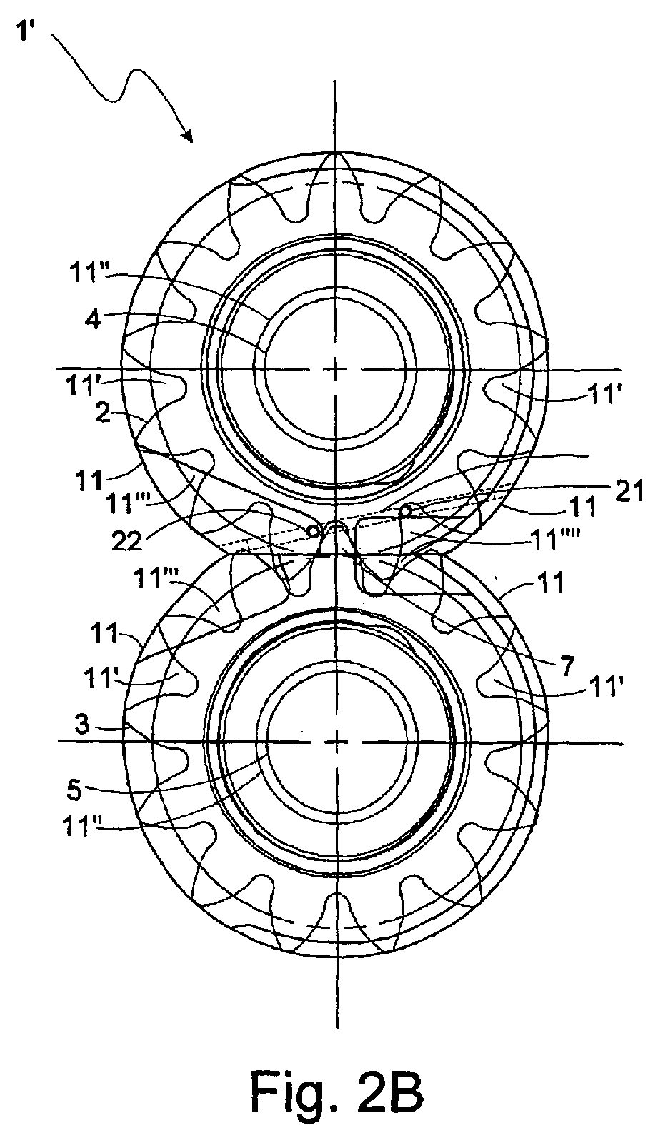
- a modified gear pump 1' is shown in Figures 2A, 2B and 2C with a passageway, 20, extending between an outlet passageway port, 21, at bearing surface 11' near output channel 11 "", and an inlet passageway port, 22, in inlet channel 11''' of rear bearing 11.
- Rear bearing 11 is shown in a side view thereof in Figure 2A and in a front view thereof in Figure 2C , and this bearing is again shown behind gears 2 and 3 in the cross section view of gear pump 1' in Figure 2B .
- Outlet passageway port 21 is located near outlet 9 but at bearing surface 11' just outside of output channel 11''''' so that pressurized fluid at the pump output is forced into that port and then through connected passageway 20 whenever a gear tooth on gear 2 is not over the port.
- Front bearing 11, on the opposite side of gears 2 and 3 from rear bearing 11 shown in Figures 2A, 2B and 2C , can also be configured to provide fluid under pressure to the inter-tooth volumes near what would otherwise be cavitation sites from the opposite side of these gears to thereby act to fill those volumes faster.
- inlet passageway port 22 at a location in inlet channel 11''' near those locations where cavitation can otherwise be expected to occur allows the pressurized fluid in passageway 20 to be forced through connected inlet passageway port 22 into inlet channel 11''' near those cavitation associated locations just at those times the inter-tooth volume is beginning to increase because of the gear teeth there beginning to come out of mesh to thereby reduce or eliminate occurrences of cavitation events there.
- inlet passageway port 22 is shown in Figure 2B to be in inlet channel 11''' near the roots of meshed gear teeth of gear 2 where it is positioned past meshing location 7 approximately a half the width of a gear tooth on gear 3 from the axis intersecting the axes of symmetry of shafts 4 and 5 as those shafts are positioned in cross section bushings 11 " of bearings 11.
- Pressurized fluid is forced out of inlet passageway port 22 into inlet channel 11''' and then into the sequence of inter-tooth volumes between the teeth of gear 2 that come adjacent thereto from each of which corresponding teeth of gear 3 are sequentially exiting. In doing so, this forced flow from inlet passageway port 22 into inlet channel 11''' entrains with it fluid flowing into inlet channel 11''' from inlet 8 to be forced therewith into the inter-tooth volumes.
- outlet passageway port 21 is located near the roots of teeth on gear 2 and positioned behind a tooth on gear 2 going into mesh at meshing location 7 approximately the width of that gear tooth on gear 2 from the axis intersecting the axes of symmetry of shafts 4 and 5, as those shafts are positioned in cross section bushings 11" of bearings 11, plus half of the inter-tooth spacing of gear teeth on that gear.
- inlet passageway port 22 can instead be located in output channel 11'''' to provide a continuous flow of pressurized fluid from the pump output through passageway 20 to enter inlet channel 11'''.
- passageway 20 is provided in bearing 11 extending along a chord of a circle about the outer periphery of the upper portion of bearing 11 in the "figure 8" configuration shown at an angle to the axis intersecting the axes of symmetry of shafts 4 and 5 as those shafts are positioned in cross section bushings 11" of bearings 11.
- This passageway extends parallel to bearing surface 11' but deep enough below that surface to be below the bottoms of inlet and outlet channels 11''' and 11''''.
- This passageway is formed by a hole drilled through this portion of bearing 11 along the chord mentioned from one side of the bearing to the other.
- Outlet passageway port 21 is drilled as a blind hole to intersect the hole drilled for passageway 20 as is inlet passageway port 22.
- the opposite ends of the hole drilled for passageway 20 have plugs inserted therein short of reaching the corresponding one of the inlet and outlet passageway ports to thereby prevent pressurized fluid from being forced out of either of the ends of this passageway hole.
- Cavitation can occur in more than one location near inlet 8 in the pump of Figure 1 .
- FIG 4 a side cross section view is shown of a further pump 1" modified from pump 1' in Figure 3 by adding a slot, 22', in the bottom of inlet channel 11''' extending along that bottom from inlet passageway port 22 to aid in filling the the sequence of adjacent inter-tooth volumes.
- FIG. 5 a side cross section view is shown in Figure 5 of a further pump 1''' modified from pump 1' in Figure 3 in which a second passageway, 23, is provided along a chord of a circle about the outer periphery of the lower portion of bearing 11 in the "figure 8" configuration shown, again at an angle to the axis intersecting the axes of symmetry of shafts 4 and 5 as those shafts are positioned in cross section bushings 11" of bearings 11.
- Passageway 23 extends between an outlet passageway port, 24, at another part of bearing surface 11' near output channel 11''', and an inlet passageway port, 25, at another part of inlet channel 11''' of rear bearing 11.
- this passageway extends parallel to bearing surface 11' but deep enough below that surface to be below the bottoms of inlet and outlet channels 11''' and 11''''.
- inlet passageway port 25 is located in inlet channel 11''' adjacent to where the sequence of inter-tooth volumes between the teeth of gear 3 each have corresponding teeth of gear 2 sequentially exiting. This allows pressurized fluid in passageway 23 to be forced through connected inlet passageway port 25 into inlet channel 11''' just at those times the inter-tooth volume is beginning to increase because of the gear teeth there beginning to come out of mesh to thereby reduce or eliminate occurrences of cavitation events there because of gear teeth on gear 3 uncovering then outlet passageway port 24.
- inlet passageway port 25 The location shown in Figure 5 for inlet passageway port 25 is in inlet channel 11''' near the roots of the first unmeshing gear tooth ahead of the currently meshed gear tooth of gear 3 at meshing location 7 where it is positioned approximately half of the width of a gear tooth on gear 3 from the axis intersecting the axes of symmetry of shafts 4 and 5, as those shafts are positioned in cross section bushings 11" of bearings 11, plus the inter-tooth spacing of gear teeth on that gear.
- Pressurized fluid is forced out of inlet passageway port 25 into inlet channel 11''' and then into the sequence of inter-tooth volumes between the teeth of gear 3 that come adjacent thereto from each of which corresponding teeth of gear 2 are sequentially exiting. This forced flow from inlet passageway port 25 into inlet channel 11''' entrains with it fluid flowing into inlet channel 11''' from inlet 8 to be forced therewith into the inter-tooth volumes.
- outlet passageway port 24 is located near the roots of teeth on gear 3 and positioned behind a tooth on gear 3 going into mesh at meshing location 7 approximately the width of one and a half gear teeth on gear 3 from the axis intersecting the axes of symmetry of shafts 4 and 5, as those shafts are positioned in cross section bushings 11" of bearings 11, plus the inter-tooth spacing of gear teeth on that gear.
- the inlet passageway port can instead be located in output channel 11'''' to thereby provide a continuous flow of pressurized fluid from the pump output through the second passageway to enter inlet channel 11'''.
- a side cross section view is shown in Figure 6 of another pump 1'''' modified from pump 1''' in Figure 5 .
- Pump 1'''' is shown there with a second passageway, 23', that extends along a chord of a circle about the outer periphery of the lower portion of bearing 11 in the "figure 8" configuration shown, perpendicular to the axis intersecting the axes of symmetry of shafts 4 and 5 as those shafts are positioned in cross section bushings 11" of bearings 11.
- Passageway 23' is shown extending from inlet passageway port 25 in inlet channel 11''', as in Figure 5 , to a relocated outlet passageway port, 24', in outlet channel 11'''' shown in Figure 6 for this continuous flow purpose.
- Outlet passageway port 24' is located near the roots of teeth on gear 3 and positioned behind a tooth on gear 3 going into mesh at meshing location 7 approximately the width of half a gear tooth on gear 3 from the axis intersecting the axes of symmetry of shafts 4 and 5, as those shafts are positioned in cross section bushings 11" of bearings 11.
- the configuration chosen for gears 2 and 3, and the configuration chosen for both inlet channel 11''' and outlet channel 11'''' determine to a substantial extent the useable locations for the inlet and outlet passageway ports and the passageways therebetween.
- the side cross section view shown in Figure 7 is a limited representation of another pump 1 v modified from pump 1''' in Figure 5 with differently shaped and positioned inlet and outlet channels, 11 v and 11 vi , respectively, from those shown in Figure 5 . This leads in turn to some differences in positioning of the inlet and outlet passageway ports and the passageways therebetween ranging from slight to significant, and so redesignated passageways, 20' and 23", are indicated in the figure.
- the former of these passageways extends between a redesignated outlet passageway port, 21', and a redesignated inlet passageway port, 22', and passageway 23" extends between a redesignated between a redesignated outlet passageway port, 24", and a redesignated inlet passageway port, 25".
Landscapes
- Engineering & Computer Science (AREA)
- Mechanical Engineering (AREA)
- General Engineering & Computer Science (AREA)
- Rotary Pumps (AREA)
Abstract
Description
- The present invention relates to hydrostatic or positive displacement pumps and, more particularly, to external gear pumps.
- Gear pumps have therein a pair of rotating gears with gear teeth that come into, and then leave, a meshing with those of the other. They thereby continually trap fluid portions at one location and displace those fluid portions to another location so, as a result, to effect a pumping of that fluid. The cross section side view schematic diagram of
Figure 1A shows an external gear pump, 1. Such a pump typically has two identical spur gears, 2 and 3, each with gear teeth arrayed about the outer periphery thereof and each mounted on, or integrally supported by, a corresponding one of a pair of gear shafts, 4 and 5, with these gears contained in a pump housing, 6. The teeth of these gears mesh with one another at a mesh location, 7, through having one or more gear teeth of one coming into, and leaving, mesh with one or more gear teeth of the other because of those gears being rotated in selected rotation directions by a selectively operated motor (not shown). When operatedgear 2 is rotating clockwise, and so resulting ingear 3 rotating counterclockwise, pump 1 draws the fluid to be pumped through an inlet opening, 8, inhousing 6, as indicated by the broad, flat arrow shown there, to be transported by rotatinggears housing 6 at the outer periphery of those gears to an outlet opening, 9, inhousing 6 at which the fluid exits the pump as indicated by the broad, flat arrow shown there. -
Figure 1B is a perspective schematic diagram providing more detail of the internal mechanisms ofpump 1 through presenting same outside ofhousing 6. The figure shows a portion of a motor drive shaft, 10, extending from the unseen operating motor through the side ofhousing 6 to connect to gear shaft 4 (which alternatively may merely be extended to form drive shaft 10), as the basis for that motor to force rotation ofgear 2 mounted on that shaft in the rotation direction selected therefor. Here,gear 2 is shown rotated in the clockwise direction to be consistent with the fluid flow direction along the primary paths of the fluid being pumped through its being transported from the intake side ofpump 1 to the discharge side thereof which are shown by broad, flat arrows inFigure 1B . This rotation ofgear 2 in turn forces gear 3 ongear shaft 5, through the meshing of the two gears atmesh location 7, to also rotate but in the opposite rotation direction, or counterclockwise.Gear shafts - Each of
bearings 11 comprises a ring-like structure that has a flat, but partially recessed, bearing surface, 11', facing the one ofgears gear shafts bearings 11 has a circular cross section bushing, 11'', in the center of its ring-like structure which extends perpendicular to the bearing surface it intersects in being aligned with the symmetry axis of the gear shaft positioned therein. - Since the two ring-like structures of
bearings 11 on the same side of each of the gears are closely adjacent to one another, they can be, and usually are, structurally or integrally joined together in a structure resembling a "figure 8" when viewed from a direction parallel to the axes of symmetry of the gear shafts when positioned therein. The pairs ofbearings 11 at opposite ends of the gear shafts for each of the gears or, alternatively, the pair of "figure 8"structures 11 at the opposite ends of the gear shafts of both gears, are held inhousing 6 so that this housing surrounds the gears and those bearings. As indicated above,gear shaft 4 is connectable to, or extendable as,motor drive shaft 10 in one or the other extending through the housing wall. When assembled in this housing, there is for the most part very little clearance between the flat parts of the bearing surfaces and the corresponding bearing surface side of the gear across therefrom to provide one basis for keeping the fluid being pumped from escaping out the sides of the gears. - At the intake side of
pump 1, inlet opening 8 in the wall ofpump housing 6 forms an inlet port at which fluid to be pumped is drawn to enter bygears outlet opening 9 at the discharge side of the pump. The very small clearances between the tips of the teeth on the gears and the corresponding housing wall interior surface, the speed of movement of the gear teeth tips along that surface, and the close proximity of the flat bearing surfaces to the sides of the gears, as described above, keep the fluid in the inter-tooth volumes trapped to prevent same from leaking backward towards the input port. - At the discharge side of the pump, outlet opening 9 in the wall of
housing 6 forms an outlet port at which fluid is being forced to exit bygears gears location 7 which is more or less along an axis there joining the axes of symmetry ofgear shafts - Cavitation can occur in external gear pumps on the intake side of the pump in a region, 12, in which the teeth of
gears inlet port 8 under the inlet port fluid pressure. In these circumstances, the local fluid pressure decreases below the vapor pressures of dissolved gases in the fluid, or the vapor pressure of the pumped fluid itself, so as to rupture the continuity of the fluid at some particle or solid surface nucleation site and thereby form a cavity or bubble. Such gases, or the vapors of the fluid, or both, evaporate into that cavity from the surrounding fluid medium. - As the inter-tooth volumes subsequently become more filled, the rising local fluid pressure forces such cavities or bubbles toward collapse causing the pressure and the temperature of the vapors therein to increase. This continues until the volume of those cavities or bubbles become a very small fraction of their original sizes to finally reach a point of total collapse, and so to result in an acoustic shock wave occurring in a very small volume that dissipates the vapors into the surrounding fluid medium. Such collapses occurring on or near surfaces of the gear teeth can erode them to thereby leave pits at those surfaces which, in occurring repeatedly, can be very destructive of the gear teeth surfaces.
- Because of occurrences of such unwanted cavitation, bearing
surfaces 11' have often been recessed inward into the bearing to have those bearings be provided with channels, 11''' and 11'''' (not seen inFigure 1B ), therein that begin adjacent tolocation 7 wheregears shafts cross section bushings 11", and the channels extend along these directions to corresponding ones of outer edge portions of bearing ring-like structures, or the "figure 8" structures, 11. At these outer edges, such channels may extend over a circular arc that is an eighth or more of the circular outer edge. Thus, there are two such channels,input channel 11''' andoutput channel 11'''' (not seen inFigure 1B ), each directed from a corresponding beginning location nearlocation 7 and extending in opposite directions to each terminate at an outer edge ofstructure 11 near, respectively, a corresponding one ofinlet 8 andoutlet 9.Output channel 11'''' (not seen inFigure 1B ) accommodates the pumped fluid being squeezed out between the gear teeth coming into mesh nearoutlet 9, andinput channel 11''' accommodates the pump incoming fluid rushing in between the gear teeth coming out of mesh nearinlet 8. - Even with such accommodations, however, the rate at which the returning fluid fills the expanding inter-tooth volume depends on the fluid pressure at the inlet port. Hence, beyond some rotation rate, this fluid inter-tooth volume filling rate will be insufficient to keep up with the expanding inter-tooth volume rate so as to still result in cavitation occurring. Thus, there is a desire for a gear pump with an arrangement for reducing further, or eliminating, cavitation occurrences during operation thereof.
- From one aspect the present invention provides a gear pump for operating with reduced likelihood of cavitation occurrences in the fluid being pumped thereby, the pump having a pair of gears each supported on a corresponding one of a pair of gear shafts between shaft ends thereof with each gear shaft having a corresponding gear shaft axis of symmetry intersecting the shaft ends thereof substantially parallel to one another, and each gear intersecting a common gear plane substantially perpendicular to the gear shaft axes of symmetry with teeth provided in each gear that mesh with at least one tooth of the other when such teeth have been rotated into a meshing region in the gear plane, and with one of the gear shafts being rotatably connectable to a motor. Bearing structures rotatably support corresponding ones of each of the pair of gear shafts on either side of that one of the pair of gears supported thereby, and with the bearing structures having bearing surfaces adjacent those gear sides. A pressurized fluid passageway is provided in at least one of the bearing structures across from the meshing region and extending between surface openings at the bearing surface of that bearing structure that are positioned on opposite sides of an alignment axis in that bearing surface extending between the gear shaft axes of symmetry, the surface openings being separated from one another by at least the width of a tooth provided in the pair of gears.
-
-
Figures 1A and 1B show side cross section and perspective unhoused views, respectively, of a gear pump, -
Figures 2A, 2B and 2C show side and front views of a portion of, and a side cross section view of, a gear pump of the present invention, -
Figure 3 shows a side cross section view of a portion of the gear pump shown inFigure 2 , -
Figure 4 shows a side cross section view of a portion of a gear pump of another embodiment of the present invention, -
Figure 5 shows a side cross section view of a portion of a gear pump of another embodiment of the present invention, -
Figure 6 shows a side cross section view of a portion of a gear pump of another embodiment of the present invention, and -
Figure 7 shows a side cross section view of a portion of a gear pump of another embodiment of the present invention. - A modified gear pump 1' is shown in
Figures 2A, 2B and 2C with a passageway, 20, extending between an outlet passageway port, 21, atbearing surface 11' nearoutput channel 11 "", and an inlet passageway port, 22, ininlet channel 11''' ofrear bearing 11. Rear bearing 11 is shown in a side view thereof inFigure 2A and in a front view thereof inFigure 2C , and this bearing is again shown behindgears Figure 2B .Outlet passageway port 21 is located nearoutlet 9 but atbearing surface 11' just outside ofoutput channel 11'''' so that pressurized fluid at the pump output is forced into that port and then through connectedpassageway 20 whenever a gear tooth ongear 2 is not over the port. The close spacing between the sides ofgear 2 and bearingsurface 11' results in the gear tooth essentially closing offoutlet passageway port 21 when a gear tooth is over that port. Front bearing 11, on the opposite side ofgears Figures 2A, 2B and 2C , can also be configured to provide fluid under pressure to the inter-tooth volumes near what would otherwise be cavitation sites from the opposite side of these gears to thereby act to fill those volumes faster. - Thus, locating
inlet passageway port 22 at a location ininlet channel 11''' near those locations where cavitation can otherwise be expected to occur allows the pressurized fluid inpassageway 20 to be forced through connectedinlet passageway port 22 intoinlet channel 11''' near those cavitation associated locations just at those times the inter-tooth volume is beginning to increase because of the gear teeth there beginning to come out of mesh to thereby reduce or eliminate occurrences of cavitation events there. One such location forinlet passageway port 22 is shown inFigure 2B to be ininlet channel 11''' near the roots of meshed gear teeth ofgear 2 where it is positioned pastmeshing location 7 approximately a half the width of a gear tooth ongear 3 from the axis intersecting the axes of symmetry ofshafts cross section bushings 11 " ofbearings 11. This is shown in somewhat greater detail in the side cross section view inFigure 3 of a portion of the gear pump shown inFigure 2B . Pressurized fluid is forced out ofinlet passageway port 22 intoinlet channel 11''' and then into the sequence of inter-tooth volumes between the teeth ofgear 2 that come adjacent thereto from each of which corresponding teeth ofgear 3 are sequentially exiting. In doing so, this forced flow frominlet passageway port 22 intoinlet channel 11''' entrains with it fluid flowing intoinlet channel 11''' frominlet 8 to be forced therewith into the inter-tooth volumes. - During the time the teeth of
gears gear 2 coversoutlet passageway port 21 to prevent pressurized fluid from entering that port which would otherwise be forced to enterinlet channel 11''' without also acting to fill a rapidly increasing inter-tooth volume. To do so,outlet passageway port 21 is located near the roots of teeth ongear 2 and positioned behind a tooth ongear 2 going into mesh at meshinglocation 7 approximately the width of that gear tooth ongear 2 from the axis intersecting the axes of symmetry ofshafts cross section bushings 11" ofbearings 11, plus half of the inter-tooth spacing of gear teeth on that gear. Such prevention of pressurized fluid at the pump output being forced intoinlet channel 11''' to provide no useful effect increases the pumping efficiency of pump 1'. However, if desired or thought needed in some circumstances,inlet passageway port 22 can instead be located inoutput channel 11'''' to provide a continuous flow of pressurized fluid from the pump output throughpassageway 20 to enterinlet channel 11'''. - As can be seen in
Figures 2A, 2B and 2C ,passageway 20 is provided in bearing 11 extending along a chord of a circle about the outer periphery of the upper portion of bearing 11 in the "figure 8" configuration shown at an angle to the axis intersecting the axes of symmetry ofshafts cross section bushings 11" ofbearings 11. This passageway extends parallel to bearingsurface 11' but deep enough below that surface to be below the bottoms of inlet andoutlet channels 11''' and 11''''. - This passageway is formed by a hole drilled through this portion of bearing 11 along the chord mentioned from one side of the bearing to the other.
Outlet passageway port 21 is drilled as a blind hole to intersect the hole drilled forpassageway 20 as isinlet passageway port 22. The opposite ends of the hole drilled forpassageway 20 have plugs inserted therein short of reaching the corresponding one of the inlet and outlet passageway ports to thereby prevent pressurized fluid from being forced out of either of the ends of this passageway hole. - Cavitation can occur in more than one location near
inlet 8 in the pump ofFigure 1 . Thus, there may be a need to provide more than one inlet passageway port from which pressurized fluid from the outlet region in pump 1' can be forced intoinlet channel 11''' to fill the increasing inter-tooth volume. Thus, inFigure 4 , a side cross section view is shown of afurther pump 1" modified from pump 1' inFigure 3 by adding a slot, 22', in the bottom ofinlet channel 11''' extending along that bottom frominlet passageway port 22 to aid in filling the the sequence of adjacent inter-tooth volumes. - Another place that cavitation can occur is where the sequence of inter-tooth volumes between the teeth of
gear 3 each have corresponding teeth ofgear 2 sequentially exiting. Thus, a side cross section view is shown inFigure 5 of a further pump 1''' modified from pump 1' inFigure 3 in which a second passageway, 23, is provided along a chord of a circle about the outer periphery of the lower portion of bearing 11 in the "figure 8" configuration shown, again at an angle to the axis intersecting the axes of symmetry ofshafts cross section bushings 11" ofbearings 11.Passageway 23 extends between an outlet passageway port, 24, at another part of bearingsurface 11'near output channel 11'''', and an inlet passageway port, 25, at another part ofinlet channel 11''' ofrear bearing 11. Here, too, this passageway extends parallel to bearingsurface 11' but deep enough below that surface to be below the bottoms of inlet andoutlet channels 11''' and 11''''. - Here,
inlet passageway port 25 is located ininlet channel 11''' adjacent to where the sequence of inter-tooth volumes between the teeth ofgear 3 each have corresponding teeth ofgear 2 sequentially exiting. This allows pressurized fluid inpassageway 23 to be forced through connectedinlet passageway port 25 intoinlet channel 11''' just at those times the inter-tooth volume is beginning to increase because of the gear teeth there beginning to come out of mesh to thereby reduce or eliminate occurrences of cavitation events there because of gear teeth ongear 3 uncovering thenoutlet passageway port 24. The location shown inFigure 5 forinlet passageway port 25 is ininlet channel 11''' near the roots of the first unmeshing gear tooth ahead of the currently meshed gear tooth ofgear 3 at meshinglocation 7 where it is positioned approximately half of the width of a gear tooth ongear 3 from the axis intersecting the axes of symmetry ofshafts cross section bushings 11" ofbearings 11, plus the inter-tooth spacing of gear teeth on that gear. Pressurized fluid is forced out ofinlet passageway port 25 intoinlet channel 11''' and then into the sequence of inter-tooth volumes between the teeth ofgear 3 that come adjacent thereto from each of which corresponding teeth ofgear 2 are sequentially exiting. This forced flow frominlet passageway port 25 intoinlet channel 11''' entrains with it fluid flowing intoinlet channel 11''' frominlet 8 to be forced therewith into the inter-tooth volumes. - Again, during the time the teeth of
gears gear 2 coversoutlet passageway port 24 to prevent pressurized fluid from entering that port which would otherwise be forced to enterinlet channel 11''' without also acting to fill a rapidly increasing inter-tooth volume. To do so,outlet passageway port 24 is located near the roots of teeth ongear 3 and positioned behind a tooth ongear 3 going into mesh at meshinglocation 7 approximately the width of one and a half gear teeth ongear 3 from the axis intersecting the axes of symmetry ofshafts cross section bushings 11" ofbearings 11, plus the inter-tooth spacing of gear teeth on that gear. Such prevention of pressurized fluid at the pump output being forced intoinlet channel 11''' to provide no useful effect increases the pumping efficiency of pump 1'''. - Again, if desired or thought needed in some circumstances, the inlet passageway port can instead be located in
output channel 11'''' to thereby provide a continuous flow of pressurized fluid from the pump output through the second passageway to enterinlet channel 11'''. Thus, a side cross section view is shown inFigure 6 of another pump 1'''' modified from pump 1''' inFigure 5 . Pump 1'''' is shown there with a second passageway, 23', that extends along a chord of a circle about the outer periphery of the lower portion of bearing 11 in the "figure 8" configuration shown, perpendicular to the axis intersecting the axes of symmetry ofshafts cross section bushings 11" ofbearings 11. Passageway 23' is shown extending frominlet passageway port 25 ininlet channel 11''', as inFigure 5 , to a relocated outlet passageway port, 24', inoutlet channel 11'''' shown inFigure 6 for this continuous flow purpose. Outlet passageway port 24' is located near the roots of teeth ongear 3 and positioned behind a tooth ongear 3 going into mesh at meshinglocation 7 approximately the width of half a gear tooth ongear 3 from the axis intersecting the axes of symmetry ofshafts cross section bushings 11" ofbearings 11. - The configuration chosen for
gears inlet channel 11''' andoutlet channel 11'''' determine to a substantial extent the useable locations for the inlet and outlet passageway ports and the passageways therebetween. The side cross section view shown inFigure 7 is a limited representation of anotherpump 1v modified from pump 1''' inFigure 5 with differently shaped and positioned inlet and outlet channels, 11v and 11vi, respectively, from those shown inFigure 5 . This leads in turn to some differences in positioning of the inlet and outlet passageway ports and the passageways therebetween ranging from slight to significant, and so redesignated passageways, 20' and 23", are indicated in the figure. The former of these passageways extends between a redesignated outlet passageway port, 21', and a redesignated inlet passageway port, 22', andpassageway 23" extends between a redesignated between a redesignated outlet passageway port, 24", and a redesignated inlet passageway port, 25". - Although the present invention has been described with reference to preferred embodiments, workers skilled in the art will recognize that changes may be made in form and detail without departing from the scope of the invention.
Claims (14)
- A gear pump for operating with reduced likelihood of cavitation occurrences in the fluid being pumped thereby, the pump comprising:a pair of gears each supported on a corresponding one of a pair of gear shafts between shaft ends thereof with each gear shaft having a corresponding gear shaft axis of symmetry intersecting the shaft ends thereof substantially parallel to one another, and each gear intersecting a common gear plane substantially perpendicular to the gear shaft axes of symmetry with teeth provided in each gear that mesh with at least one tooth of the other when such teeth have been rotated into a meshing region in the gear plane, and with one of the gear shafts being rotatably connectable to a motor;bearing structures rotatably supporting corresponding ones of each of the pair of gear shafts on either side of that one of the pair of gears supported thereby, and with the bearing structures having bearing surfaces adjacent those gear sides; anda pressurized fluid passageway in at least one of the bearing structures across from the meshing region and extending between surface openings at the bearing surface of that bearing structure that are positioned on opposite sides of an alignment axis in that bearing surface extending between the gear shaft axes of symmetry, the surface openings being separated from one another by at least a width of a tooth provided in the pair of gears.
- The pump of claim 1 wherein each gear tooth of either of the pair of gears, in rotating to a position symmetrically about a coupling axis in the gear plane extending between the gear shaft axes of symmetry to thereby reach a full mesh position, has a plane intersecting it which also extends substantially perpendicular to the bearing surface at which the surface openings occur and which intersects those surface openings, the plane being closer to a root of each such gear tooth than a point of contact thereof with a gear tooth of the other one of the pair of gears.
- The pump of claim 1 wherein each gear tooth of either of the pair of gears, in rotating to a position symmetrically about a coupling axis in the gear plane extending between the gear shaft axes of symmetry to thereby reach a full mesh position, has a plane intersecting it which also extends substantially perpendicular to the bearing surface at which the surface openings occur and which intersects those surface openings, the plane being closer to a point of contact of each such gear tooth with a gear tooth of the other one of the pair of gears than to a root of that gear tooth.
- The pump of claim 1 wherein each gear tooth of either of the pair of gears, in rotating to a position symmetrically about a coupling axis in the gear plane extending between the gear shaft axes of symmetry to thereby reach a full mesh position, thereby positions that tooth and the following gear tooth on the same one of the pair of gears between the surface openings.
- The pump of claim 4 wherein the bearing surfaces of the bearing structures on at least one side of the pair of gears are recessed beginning at locations near to the alignment axis and from there extending in opposite directions at least in part perpendicular to that alignment axis to thereby form a pair of recessed surface portions in the bearing surfaces, and with at least one of the surface openings being at one of those recessed surface portions.
- The pump of claim 4 or 5 wherein each gear tooth of either of the pair of gears, in reaching the full mesh position, has a plane intersecting it which also extends substantially perpendicular to the bearing surface at the alignment axis and which intersects those surface openings, the plane being closer to a root of that gear tooth than a point of contact thereof with a gear tooth of the other one of the pair of gears.
- The pump of claim 4 or 5 wherein each gear tooth of either of the pair of gears, in reaching the full mesh position, has a plane intersecting it which also extends substantially perpendicular to the bearing surface at the alignment axis and which intersects those surface openings, the plane being closer to a point of contact of that gear tooth with a gear tooth of the other one of the pair of gears than to a root of that gear tooth.
- The pump of claim 1 wherein the bearing surfaces of the bearing structures on at least one side of the pair of gears are recessed beginning at locations near to where those bearing surfaces are across from an axis in the bearing plane intersecting the gear shaft axes of symmetry and from there extending in opposite directions at least in part perpendicular to that bearing plane axis to form a pair of recessed surface portions in the bearing surfaces, and with at least one of the surface openings being at one of those recessed surface portions.
- The pump of claim 8 wherein each gear tooth of either of the pair of gears reaching the full mesh position has a plane intersecting it which also extends substantially perpendicular to the bearing surface at which the surface openings occur and which intersects those surface openings, the plane position being selected from being closer to a root of that gear tooth than a point of contact thereof with a gear tooth of the other one of the pair of gears and being closer to a point of contact of that gear tooth with a gear tooth of the other one of the pair of gears than to a root of that gear tooth.
- The pump of any preceding claim wherein the pressurized fluid passageway in one of the bearing structures is a first pressurized fluid passageway extending between a first pair of surface openings at the bearing surface of that bearing structure, and further comprising a second pressurized fluid passageway in that bearing structure across from where gear teeth of the other of the pair of gears, under rotation, reach the full mesh position and extending between a second pair of surface openings at the bearing surface of that bearing structure which second pair of surface openings are across from the meshing region on either side of a width thereof.
- The pump of any of claims 1 to 9 wherein the pressurized fluid passageway in one of the bearing structures is a first pressurized fluid passageway extending between a first pair of surface openings in a first bearing structure, and further comprising a second pressurized fluid passageway in a second bearing structure across from where gear teeth of the other of the pair of gears, under rotation, reach the full mesh position and extending between a second pair of surface openings at the bearing surface of that second bearing structure which second pair of surface openings are across from the meshing region on either side of a width thereof.
- The pump of any of claims 1 to 9 wherein the pressurized fluid passageway in one of the bearing structures is a first pressurized fluid passageway extending between a first pair of surface openings in a first bearing, and further comprising a second pressurized fluid passageway in a second bearing structure on the opposite side of the one of the pair of gears from the first bearing structure and across from where gear teeth of the one of the pair of gears, under rotation, reach the full mesh position and extending between a second pair of surface openings at the bearing surface of that second bearing structure which second pair of surface openings are across from the meshing region on either side of a width thereof.
- A gear pump bearing structure having an opening therein for rotatably supporting a gear shaft at a side of a gear mounted on that shaft with the bearing structure having a bearing surface that would be adjacent to a side of such a gear with its shaft so supported that has recesses therein beginning at locations separated from one another by a separation space but near to a position on a path that would be traversed by teeth of such a gear during rotations thereof with these recesses from these separated beginning locations extending in opposite directions at least in part tangential to such a path to form a pair of recessed surface portions in the bearing surface, and further having a pressurized fluid passageway therein positioned to be across from the position that would be traversed by teeth of that gear during rotations thereof so as to extend between surface openings at the bearing surface of that bearing structure that are positioned on opposite sides of the separation space in that bearing surface.
- A gear pump for operating with reduced likelihood of cavitation occurrences in the fluid being pumped thereby, the pump comprising:a pair of gears each supported on a corresponding one of a pair of gear shafts between shaft ends thereof with one of the gear shafts being rotatably connectable to a motor;bearing structures rotatably supporting corresponding ones of each of the pair of gear shafts on either side of that one of the pair of gears supported thereby, and with the bearing structures having bearing surfaces adjacent those gear sides with at least one of those bearing surfaces having recesses therein beginning at locations separated from one another by a separation space but near to a position on paths that would be traversed by teeth of the pair of gears during rotations thereof with these recesses from these separated beginning locations extending in opposite directions at least in part tangential to such paths to form a pair of recessed surface portions in the bearing surfaces; anda pressurized fluid passageway in at least one of the bearing structures positioned to be across from the position that would be traversed by teeth of the pair of gears during rotations thereof so as to extend between surface openings at the bearing surface of that bearing structure that are positioned on opposite sides of the separation space in that bearing surface.
Applications Claiming Priority (1)
| Application Number | Priority Date | Filing Date | Title |
|---|---|---|---|
| US12/001,279 US7878781B2 (en) | 2007-12-11 | 2007-12-11 | Gear pump cavitation reduction |
Publications (3)
| Publication Number | Publication Date |
|---|---|
| EP2071122A2 true EP2071122A2 (en) | 2009-06-17 |
| EP2071122A3 EP2071122A3 (en) | 2012-10-31 |
| EP2071122B1 EP2071122B1 (en) | 2017-09-13 |
Family
ID=40456551
Family Applications (1)
| Application Number | Title | Priority Date | Filing Date |
|---|---|---|---|
| EP08253896.8A Ceased EP2071122B1 (en) | 2007-12-11 | 2008-12-05 | Gear pump cavitation reduction |
Country Status (3)
| Country | Link |
|---|---|
| US (1) | US7878781B2 (en) |
| EP (1) | EP2071122B1 (en) |
| JP (1) | JP2009162221A (en) |
Cited By (1)
| Publication number | Priority date | Publication date | Assignee | Title |
|---|---|---|---|---|
| WO2015080765A1 (en) * | 2013-11-26 | 2015-06-04 | Woodward, Inc. | Gear pump bearing dam |
Families Citing this family (21)
| Publication number | Priority date | Publication date | Assignee | Title |
|---|---|---|---|---|
| US9677559B2 (en) | 2011-02-25 | 2017-06-13 | Hamilton Sundstrand Corporation | Bearing face geometry for gear pump |
| US8992192B2 (en) | 2011-02-25 | 2015-03-31 | Hamilton Sundstrand Corporation | Input shaft lubrication for gear pump |
| US8911222B2 (en) | 2011-02-25 | 2014-12-16 | Hamilton Sundstrand Corporation | Input shaft assembly for gear pump |
| US8814547B2 (en) | 2011-02-25 | 2014-08-26 | Hamilton Sundstrand Corporation | Seal retaining sleeve for gear pump |
| US8801410B2 (en) | 2011-02-25 | 2014-08-12 | Hamilton Sundstrand Corporation | Coupling shaft for gear pump |
| US8613609B2 (en) | 2011-04-15 | 2013-12-24 | Hamilton Sundstrand Corporation | Bi-metal pump gear |
| US8992193B2 (en) | 2011-07-15 | 2015-03-31 | Hamilton Sundstrand Corporation | Shaft assembly including a contained shaft spring load |
| US8790090B2 (en) | 2011-07-26 | 2014-07-29 | Hamilton Sundstrand Corporation | Priming of gear pump in alternative attitudes |
| US9028222B2 (en) | 2011-08-26 | 2015-05-12 | Hamilton Sundstrand Corporation | Variable output pump |
| US9068568B2 (en) | 2012-07-23 | 2015-06-30 | Hamilton Sundstrand Corporation | Inlet cutbacks for high speed gear pump |
| WO2014171567A1 (en) * | 2013-04-17 | 2014-10-23 | Nag-Bok Lim | Silent gear pump suppressing tooth contact noise |
| US9776728B2 (en) | 2014-07-22 | 2017-10-03 | Hamilton Sundstrand Corporation | Dual-stage gear pump with reduced pressure ripple |
| CN104454511B (en) * | 2014-11-13 | 2016-09-07 | 福州大学 | A kind of crescent gear pump being applicable to high-pressure high-flow |
| US10563653B2 (en) | 2016-01-12 | 2020-02-18 | Hamilton Sundstrand Corporation | Gear pump |
| US10443597B2 (en) | 2016-01-12 | 2019-10-15 | Hamilton Sundstrand Corporation | Gears and gear pumps |
| US9945376B2 (en) * | 2016-03-16 | 2018-04-17 | Hamilton Sundstrand Corporation | Gear pump |
| US10590928B2 (en) * | 2017-11-28 | 2020-03-17 | GM Global Technology Operations LLC | Gear pump that removes air from pumped oil |
| US11242850B2 (en) * | 2019-08-07 | 2022-02-08 | GM Global Technology Operations LLC | Scavenge gear assembly for an oil pump of a vehicle |
| EP3904687B1 (en) * | 2020-04-28 | 2022-10-26 | Maag Pump Systems AG | Gear pump |
| JP2025542275A (en) | 2022-12-19 | 2025-12-25 | トライアンフ・エンジン・コントロール・システムズ・リミテッド・ライアビリティ・カンパニー | Enlarging the volume of the gear pump to reduce cavitation at the meshing area |
| US12486843B2 (en) | 2022-12-19 | 2025-12-02 | Triumph Engine Control Systems, Llc | Volume expansion for cavitation reduction in a gear pump mesh |
Citations (1)
| Publication number | Priority date | Publication date | Assignee | Title |
|---|---|---|---|---|
| US20070178003A1 (en) | 2005-11-22 | 2007-08-02 | Parker-Hannifin Corporation | Gear pump with ripple chamber for low noise and pressure ripples |
Family Cites Families (7)
| Publication number | Priority date | Publication date | Assignee | Title |
|---|---|---|---|---|
| US2781730A (en) * | 1952-10-22 | 1957-02-19 | Thompson Prod Inc | Implement pump |
| US3833317A (en) * | 1971-03-04 | 1974-09-03 | R Rumsey | Rotary gear motor/pump having hydrostatic bearing means |
| JPS5623512Y2 (en) * | 1974-08-30 | 1981-06-02 | ||
| DE2554105C2 (en) * | 1975-12-02 | 1984-04-05 | Robert Bosch Gmbh, 7000 Stuttgart | Gear machine (pump or motor) |
| DE2810563C2 (en) * | 1978-03-10 | 1982-10-28 | Theodorus Henricus Dipl.-Ing. Delft Korse | Gear machine (pump or motor) |
| US6042352A (en) | 1998-08-12 | 2000-03-28 | Argo-Tech Corporation | Bearing with pulsed bleed configuration |
| WO2006015218A1 (en) * | 2004-07-30 | 2006-02-09 | Pulsafeeder, Inc. | Non-metallic gear pump with magnetic coupling assembly |
-
2007
- 2007-12-11 US US12/001,279 patent/US7878781B2/en not_active Expired - Fee Related
-
2008
- 2008-12-05 EP EP08253896.8A patent/EP2071122B1/en not_active Ceased
- 2008-12-09 JP JP2008312801A patent/JP2009162221A/en not_active Ceased
Patent Citations (1)
| Publication number | Priority date | Publication date | Assignee | Title |
|---|---|---|---|---|
| US20070178003A1 (en) | 2005-11-22 | 2007-08-02 | Parker-Hannifin Corporation | Gear pump with ripple chamber for low noise and pressure ripples |
Cited By (3)
| Publication number | Priority date | Publication date | Assignee | Title |
|---|---|---|---|---|
| WO2015080765A1 (en) * | 2013-11-26 | 2015-06-04 | Woodward, Inc. | Gear pump bearing dam |
| US9303644B2 (en) | 2013-11-26 | 2016-04-05 | Woodward, Inc. | Gear pump bearing dam |
| US9932980B2 (en) | 2013-11-26 | 2018-04-03 | Woodward, Inc. | Gear pump bearing dam |
Also Published As
| Publication number | Publication date |
|---|---|
| EP2071122A3 (en) | 2012-10-31 |
| US20090148333A1 (en) | 2009-06-11 |
| JP2009162221A (en) | 2009-07-23 |
| US7878781B2 (en) | 2011-02-01 |
| EP2071122B1 (en) | 2017-09-13 |
Similar Documents
| Publication | Publication Date | Title |
|---|---|---|
| EP2071122B1 (en) | Gear pump cavitation reduction | |
| EP2726741B1 (en) | Positive-displacement rotary pump having a positive-displacement auxiliary pumping system | |
| JP6329775B2 (en) | Vane pump | |
| US6210138B1 (en) | Rotary pump apparatus and method | |
| CN104632618A (en) | Roots-style blower with leakage mechanisms | |
| CN101790622B (en) | Improved gear hydraulic device | |
| CN105917119A (en) | Gear pump bearing dam | |
| US6042352A (en) | Bearing with pulsed bleed configuration | |
| US20070178003A1 (en) | Gear pump with ripple chamber for low noise and pressure ripples | |
| CN101900120B (en) | Screw compressor | |
| JP2015140701A (en) | Self-priming pump | |
| JP4686936B2 (en) | Screw compressor | |
| JP6236064B2 (en) | Rotary piston pump with optimized inlet and outlet | |
| JP5591527B2 (en) | Internal gear pump with optimized noise suppression | |
| JPH0617765A (en) | Suction control type ring gear pump | |
| US20080063554A1 (en) | Precision flow gear pump | |
| JPH11270472A (en) | Oil pump | |
| CN114729634A (en) | Gear pump or gear motor | |
| WO2021044570A1 (en) | Helical gear pump, or helical gear motor | |
| JP2006283664A (en) | Roots pump | |
| US6652253B1 (en) | Hydraulic pump having a noise reduction recess | |
| CN106894997B (en) | A kind of compression of ring gear formation gases or expansion device | |
| US11795945B2 (en) | Pump device with air introduction hole that opens into pump chamber at predetermined opening time immediately before suction stroke | |
| JP2003227482A (en) | Roots type rotary machine with internal compression | |
| JP3642422B2 (en) | Oil pump |
Legal Events
| Date | Code | Title | Description |
|---|---|---|---|
| PUAI | Public reference made under article 153(3) epc to a published international application that has entered the european phase |
Free format text: ORIGINAL CODE: 0009012 |
|
| AK | Designated contracting states |
Kind code of ref document: A2 Designated state(s): AT BE BG CH CY CZ DE DK EE ES FI FR GB GR HR HU IE IS IT LI LT LU LV MC MT NL NO PL PT RO SE SI SK TR |
|
| AX | Request for extension of the european patent |
Extension state: AL BA MK RS |
|
| PUAL | Search report despatched |
Free format text: ORIGINAL CODE: 0009013 |
|
| AK | Designated contracting states |
Kind code of ref document: A3 Designated state(s): AT BE BG CH CY CZ DE DK EE ES FI FR GB GR HR HU IE IS IT LI LT LU LV MC MT NL NO PL PT RO SE SI SK TR |
|
| AX | Request for extension of the european patent |
Extension state: AL BA MK RS |
|
| RIC1 | Information provided on ipc code assigned before grant |
Ipc: F01C 1/08 20060101AFI20120927BHEP Ipc: F01C 21/02 20060101ALI20120927BHEP Ipc: F04C 2/18 20060101ALI20120927BHEP Ipc: F01C 1/18 20060101ALI20120927BHEP Ipc: F04C 2/08 20060101ALI20120927BHEP |
|
| 17P | Request for examination filed |
Effective date: 20130430 |
|
| AKX | Designation fees paid |
Designated state(s): DE FR GB |
|
| REG | Reference to a national code |
Ref country code: DE Ref legal event code: R079 Ref document number: 602008052091 Country of ref document: DE Free format text: PREVIOUS MAIN CLASS: F01C0001080000 Ipc: F04C0014260000 |
|
| GRAP | Despatch of communication of intention to grant a patent |
Free format text: ORIGINAL CODE: EPIDOSNIGR1 |
|
| STAA | Information on the status of an ep patent application or granted ep patent |
Free format text: STATUS: GRANT OF PATENT IS INTENDED |
|
| RIC1 | Information provided on ipc code assigned before grant |
Ipc: F04C 2/18 20060101ALI20170428BHEP Ipc: F04C 15/00 20060101ALI20170428BHEP Ipc: F04C 14/26 20060101AFI20170428BHEP Ipc: F04C 2/08 20060101ALI20170428BHEP |
|
| INTG | Intention to grant announced |
Effective date: 20170601 |
|
| GRAS | Grant fee paid |
Free format text: ORIGINAL CODE: EPIDOSNIGR3 |
|
| GRAA | (expected) grant |
Free format text: ORIGINAL CODE: 0009210 |
|
| STAA | Information on the status of an ep patent application or granted ep patent |
Free format text: STATUS: THE PATENT HAS BEEN GRANTED |
|
| AK | Designated contracting states |
Kind code of ref document: B1 Designated state(s): DE FR GB |
|
| REG | Reference to a national code |
Ref country code: GB Ref legal event code: FG4D |
|
| REG | Reference to a national code |
Ref country code: DE Ref legal event code: R096 Ref document number: 602008052091 Country of ref document: DE |
|
| REG | Reference to a national code |
Ref country code: FR Ref legal event code: PLFP Year of fee payment: 10 |
|
| REG | Reference to a national code |
Ref country code: DE Ref legal event code: R097 Ref document number: 602008052091 Country of ref document: DE |
|
| PLBE | No opposition filed within time limit |
Free format text: ORIGINAL CODE: 0009261 |
|
| STAA | Information on the status of an ep patent application or granted ep patent |
Free format text: STATUS: NO OPPOSITION FILED WITHIN TIME LIMIT |
|
| 26N | No opposition filed |
Effective date: 20180614 |
|
| PGFP | Annual fee paid to national office [announced via postgrant information from national office to epo] |
Ref country code: FR Payment date: 20211118 Year of fee payment: 14 Ref country code: GB Payment date: 20211118 Year of fee payment: 14 Ref country code: DE Payment date: 20211117 Year of fee payment: 14 |
|
| REG | Reference to a national code |
Ref country code: DE Ref legal event code: R119 Ref document number: 602008052091 Country of ref document: DE |
|
| GBPC | Gb: european patent ceased through non-payment of renewal fee |
Effective date: 20221205 |
|
| PG25 | Lapsed in a contracting state [announced via postgrant information from national office to epo] |
Ref country code: GB Free format text: LAPSE BECAUSE OF NON-PAYMENT OF DUE FEES Effective date: 20221205 Ref country code: DE Free format text: LAPSE BECAUSE OF NON-PAYMENT OF DUE FEES Effective date: 20230701 |
|
| PG25 | Lapsed in a contracting state [announced via postgrant information from national office to epo] |
Ref country code: FR Free format text: LAPSE BECAUSE OF NON-PAYMENT OF DUE FEES Effective date: 20221231 |