EP2070885B1 - Method of fabricating optical fiber using an isothermal, low pressure plasma depostion technique - Google Patents
Method of fabricating optical fiber using an isothermal, low pressure plasma depostion technique Download PDFInfo
- Publication number
- EP2070885B1 EP2070885B1 EP08021208.7A EP08021208A EP2070885B1 EP 2070885 B1 EP2070885 B1 EP 2070885B1 EP 08021208 A EP08021208 A EP 08021208A EP 2070885 B1 EP2070885 B1 EP 2070885B1
- Authority
- EP
- European Patent Office
- Prior art keywords
- substrate tube
- plasma
- deposition
- tube
- isothermal
- Prior art date
- Legal status (The legal status is an assumption and is not a legal conclusion. Google has not performed a legal analysis and makes no representation as to the accuracy of the status listed.)
- Ceased
Links
- 238000000034 method Methods 0.000 title claims description 42
- 239000013307 optical fiber Substances 0.000 title claims description 7
- 238000004519 manufacturing process Methods 0.000 title description 5
- 239000000758 substrate Substances 0.000 claims description 61
- 238000000151 deposition Methods 0.000 claims description 57
- 230000008021 deposition Effects 0.000 claims description 51
- 230000008569 process Effects 0.000 claims description 32
- 238000006243 chemical reaction Methods 0.000 claims description 24
- VYPSYNLAJGMNEJ-UHFFFAOYSA-N Silicium dioxide Chemical compound O=[Si]=O VYPSYNLAJGMNEJ-UHFFFAOYSA-N 0.000 claims description 19
- 239000000463 material Substances 0.000 claims description 17
- 238000011144 upstream manufacturing Methods 0.000 claims description 16
- 239000000376 reactant Substances 0.000 claims description 13
- 238000010438 heat treatment Methods 0.000 claims description 8
- 239000000377 silicon dioxide Substances 0.000 claims description 8
- 239000000203 mixture Substances 0.000 claims description 7
- 239000000126 substance Substances 0.000 claims description 7
- 239000006227 byproduct Substances 0.000 claims description 5
- 150000002500 ions Chemical class 0.000 claims description 3
- 239000000047 product Substances 0.000 claims 1
- 238000005201 scrubbing Methods 0.000 claims 1
- 239000011521 glass Substances 0.000 description 14
- 239000002245 particle Substances 0.000 description 11
- 239000004071 soot Substances 0.000 description 9
- 238000005253 cladding Methods 0.000 description 6
- 238000005137 deposition process Methods 0.000 description 6
- 230000005672 electromagnetic field Effects 0.000 description 5
- 230000015572 biosynthetic process Effects 0.000 description 4
- 239000007789 gas Substances 0.000 description 4
- 239000006060 molten glass Substances 0.000 description 4
- 229910052732 germanium Inorganic materials 0.000 description 3
- 238000005245 sintering Methods 0.000 description 3
- XKRFYHLGVUSROY-UHFFFAOYSA-N Argon Chemical compound [Ar] XKRFYHLGVUSROY-UHFFFAOYSA-N 0.000 description 2
- 229910006113 GeCl4 Inorganic materials 0.000 description 2
- 229910003910 SiCl4 Inorganic materials 0.000 description 2
- 239000012190 activator Substances 0.000 description 2
- 230000008901 benefit Effects 0.000 description 2
- 238000005229 chemical vapour deposition Methods 0.000 description 2
- 239000000835 fiber Substances 0.000 description 2
- GNPVGFCGXDBREM-UHFFFAOYSA-N germanium atom Chemical compound [Ge] GNPVGFCGXDBREM-UHFFFAOYSA-N 0.000 description 2
- 238000006386 neutralization reaction Methods 0.000 description 2
- 230000003287 optical effect Effects 0.000 description 2
- 239000002243 precursor Substances 0.000 description 2
- 229910052710 silicon Inorganic materials 0.000 description 2
- 239000010703 silicon Substances 0.000 description 2
- FDNAPBUWERUEDA-UHFFFAOYSA-N silicon tetrachloride Chemical compound Cl[Si](Cl)(Cl)Cl FDNAPBUWERUEDA-UHFFFAOYSA-N 0.000 description 2
- IEXRMSFAVATTJX-UHFFFAOYSA-N tetrachlorogermane Chemical compound Cl[Ge](Cl)(Cl)Cl IEXRMSFAVATTJX-UHFFFAOYSA-N 0.000 description 2
- 238000007740 vapor deposition Methods 0.000 description 2
- 230000008016 vaporization Effects 0.000 description 2
- PXGOKWXKJXAPGV-UHFFFAOYSA-N Fluorine Chemical compound FF PXGOKWXKJXAPGV-UHFFFAOYSA-N 0.000 description 1
- 230000002411 adverse Effects 0.000 description 1
- 229910052786 argon Inorganic materials 0.000 description 1
- 238000005234 chemical deposition Methods 0.000 description 1
- 239000000470 constituent Substances 0.000 description 1
- 230000008878 coupling Effects 0.000 description 1
- 238000010168 coupling process Methods 0.000 description 1
- 238000005859 coupling reaction Methods 0.000 description 1
- 238000005336 cracking Methods 0.000 description 1
- 238000000354 decomposition reaction Methods 0.000 description 1
- 230000001627 detrimental effect Effects 0.000 description 1
- 230000000694 effects Effects 0.000 description 1
- 238000005516 engineering process Methods 0.000 description 1
- 229910052731 fluorine Inorganic materials 0.000 description 1
- 239000011737 fluorine Substances 0.000 description 1
- 230000004927 fusion Effects 0.000 description 1
- 238000010574 gas phase reaction Methods 0.000 description 1
- -1 germanium silicates Chemical class 0.000 description 1
- WMIYKQLTONQJES-UHFFFAOYSA-N hexafluoroethane Chemical compound FC(F)(F)C(F)(F)F WMIYKQLTONQJES-UHFFFAOYSA-N 0.000 description 1
- 239000001257 hydrogen Substances 0.000 description 1
- 229910052739 hydrogen Inorganic materials 0.000 description 1
- 230000006698 induction Effects 0.000 description 1
- 230000001939 inductive effect Effects 0.000 description 1
- 230000003993 interaction Effects 0.000 description 1
- 230000007246 mechanism Effects 0.000 description 1
- 239000002994 raw material Substances 0.000 description 1
- 230000009257 reactivity Effects 0.000 description 1
- 150000003377 silicon compounds Chemical class 0.000 description 1
- 238000009987 spinning Methods 0.000 description 1
- 230000007480 spreading Effects 0.000 description 1
- 238000003892 spreading Methods 0.000 description 1
- 230000007704 transition Effects 0.000 description 1
- 238000009834 vaporization Methods 0.000 description 1
Images


Classifications
-
- C—CHEMISTRY; METALLURGY
- C03—GLASS; MINERAL OR SLAG WOOL
- C03B—MANUFACTURE, SHAPING, OR SUPPLEMENTARY PROCESSES
- C03B37/00—Manufacture or treatment of flakes, fibres, or filaments from softened glass, minerals, or slags
- C03B37/01—Manufacture of glass fibres or filaments
- C03B37/012—Manufacture of preforms for drawing fibres or filaments
- C03B37/014—Manufacture of preforms for drawing fibres or filaments made entirely or partially by chemical means, e.g. vapour phase deposition of bulk porous glass either by outside vapour deposition [OVD], or by outside vapour phase oxidation [OVPO] or by vapour axial deposition [VAD]
- C03B37/018—Manufacture of preforms for drawing fibres or filaments made entirely or partially by chemical means, e.g. vapour phase deposition of bulk porous glass either by outside vapour deposition [OVD], or by outside vapour phase oxidation [OVPO] or by vapour axial deposition [VAD] by glass deposition on a glass substrate, e.g. by inside-, modified-, plasma-, or plasma modified- chemical vapour deposition [ICVD, MCVD, PCVD, PMCVD], i.e. by thin layer coating on the inside or outside of a glass tube or on a glass rod
- C03B37/01807—Reactant delivery systems, e.g. reactant deposition burners
- C03B37/01815—Reactant deposition burners or deposition heating means
- C03B37/01823—Plasma deposition burners or heating means
- C03B37/0183—Plasma deposition burners or heating means for plasma within a tube substrate
-
- C—CHEMISTRY; METALLURGY
- C03—GLASS; MINERAL OR SLAG WOOL
- C03B—MANUFACTURE, SHAPING, OR SUPPLEMENTARY PROCESSES
- C03B37/00—Manufacture or treatment of flakes, fibres, or filaments from softened glass, minerals, or slags
- C03B37/01—Manufacture of glass fibres or filaments
- C03B37/012—Manufacture of preforms for drawing fibres or filaments
- C03B37/014—Manufacture of preforms for drawing fibres or filaments made entirely or partially by chemical means, e.g. vapour phase deposition of bulk porous glass either by outside vapour deposition [OVD], or by outside vapour phase oxidation [OVPO] or by vapour axial deposition [VAD]
- C03B37/018—Manufacture of preforms for drawing fibres or filaments made entirely or partially by chemical means, e.g. vapour phase deposition of bulk porous glass either by outside vapour deposition [OVD], or by outside vapour phase oxidation [OVPO] or by vapour axial deposition [VAD] by glass deposition on a glass substrate, e.g. by inside-, modified-, plasma-, or plasma modified- chemical vapour deposition [ICVD, MCVD, PCVD, PMCVD], i.e. by thin layer coating on the inside or outside of a glass tube or on a glass rod
- C03B37/01846—Means for after-treatment or catching of worked reactant gases
Definitions
- the present invention relates to a plasma technique for depositing material in a substrate tube and, more particularly, to an isothermal, low pressure process that results in creating an extremely narrow reaction zone in the tube within which a more uniform and efficient deposition will occur.
- Optical fiber typically contains a high-purity silica glass core optionally doped with a refractive index-raising element (such as germanium), an inner cladding of high-purity silica glass optionally doped with a refractive index-lowering element (such as fluorine), and an outer cladding of undoped silica glass.
- a refractive index-raising element such as germanium
- a refractive index-lowering element such as fluorine
- the preforms for making such fiber are fabricated by using a glass tube for the outer cladding (referred to as an overcladding tube), and separately forming a core rod containing the core and inner cladding material.
- the core rods are fabricated by any of a variety of vapor deposition methods known to those skilled in the art, including vapor axial deposition (VAD), outside vapor deposition (OVD), and modified chemical vapor deposition (MCVD).
- MCVD for example, involves passing a high-purity gas, e.g., a mixture of gases containing silicon and germanium, through the interior of a silica tube (also referred to as a "substrate tube”) while heating the outside of the tube with a traversing oxy-hydrogen torch. In the heated area of the tube, a gas phase reaction occurs that deposits particles on the tube wall. This deposit, which forms ahead of the torch (referred to as "downstream”), is sintered as the torch passes over it.
- a high-purity gas e.g., a mixture of gases containing silicon and germanium
- the process is repeated in successive passes until the requisite quantity of silica and/or germanium-doped silica is deposited.
- the body is heated to collapse the substrate tube and obtain a consolidated core rod in which the substrate tube constitutes the outer portion of the inner cladding material.
- the overcladding tube is typically placed over the core rod, and the components are heated and collapsed into the final preform structure.
- a plasma chemical vapor deposition (PCVD) process may be used.
- the substrate tube passes through a microwave applicator (also referred to as an activator chamber, or activator head), which forms an electro-magnetic field around and inside the tube.
- a non-isothermal, low-pressure plasma is generated inside the tube by the interaction of the electro-magnetic field with the feed (e.g., SiCl 4 , GeCl 4 , and O 2 ). Chemical reactions are then enabled to form glass particles that deposit themselves on the inside of the tube.
- An external heat source (such as a furnace) is required in PCVD to heat the substrate during deposition to ensure that the deposited glass is of a form that can be subsequently fused to clear glass.
- the body is heated to collapse the substrate tube (in a manner similar to MCVD) and obtain a consolidated core rod in which the substrate tube constitutes the outer portion of the inner cladding material.
- an overcladding tube is typically placed over the core rod, and the components are heated and collapsed into the final preform structure.
- the reaction takes place within the created plasma region, the length of which is generally 10-20% of the overall substrate tube length.
- MCVD there is a variation in reactivity within the plasma, resulting in variations in the thickness and/or composition of the reacted components. Therefore, the glass that is deposited on the inside of the substrate tube at any given time using a PCVD process can be non-uniform in terms of thickness and/or composition.
- the deposited cores in preforms made by these processes may vary in diameter and optical properties along the deposited length, also affecting the quality of the resulting fiber.
- the soot formed in the reaction zone is capable of traveling the length of the tube and can potentially deposit itself at any point along the tube, regardless of the reaction zone location, thus leading to a certain degree of unpredictability in the deposition process.
- EP 0 005 963 A1 describes a method of depositing glass on a substrate tube using a plasma process.
- Silica is deposited on the inner surface of the tube from the decomposition of a volatile silicon compound in a hot intense inductive plasma material by the application of radio frequency power from a generator via a coupling coil and a matching coil.
- the invention relates to a plasma technique for depositing material within a substrate tube and, more particularly, to an isothermal, low-pressure plasma process that results in creating a narrow reaction zone within which a more uniform and efficient deposition will occur.
- isothermal, low pressure plasma operating conditions have been found that generate a narrow deposition zone upstream of the plasma (i.e., a location between the introduction of the reactant materials and the plasma). These operating conditions depend upon a number of interacting parameters. In essence, the key objective is to provide sufficient energy density for the creation of a narrow reaction zone, while not exceeding a heat level that would otherwise vaporize the inner surface of the substrate tube.
- the exhaust end of the substrate tube is connected, through a vacuum system, to a scrubber apparatus for removal and neutralization of reaction by-products.
- the isothermal, low pressure deposition process is particularly well-suited for the manufacture of optical fiber core rods that require precision core profiles (such as, for example, multimode core rods), since the deposition occurs in a very narrow zone (generally about one centimeter or less), in very thin layers, and does not require sintering.
- FIG. 1 illustrates an exemplary apparatus 10 that may be used to practice the low pressure, isothermal deposition method of the present invention.
- apparatus 10 several operating parameters of apparatus 10 are controlled to allow for the formation of an extremely narrow deposition zone immediately upstream of the created plasma.
- the deposition conditions are controlled such that the narrow deposition zone occupies about only 1% of the length of a conventional substrate tube (as opposed to the 10-30% values associated with the prior art MCVD and PCVD processes). More broadly, the particularly conditions utilized with the teachings of the present invention result in a narrow deposition zone of one centimeter or less.
- a silica tube 12 is used in apparatus 10 as the substrate tube within which the deposition will occur, where the inner diameter (ID) and outer diameter (OD) of tube 12 are two of the operating parameters that are accounted for in developing the proper set of narrow zone deposition conditions, since the wall thickness also has an effect on the temperature of the inside wall and the reaction chemistry at the wall's surface.
- Apparatus 10 further comprises a chemical delivery system 14 to deliver one or more chemical reactants (such as GeCl 4 , SiCl 4 , C 2 F 6 and O 2 ) into substrate tube 12 through a first seal 16 formed within a first end of tube 12.
- a chemical delivery system 14 to deliver one or more chemical reactants (such as GeCl 4 , SiCl 4 , C 2 F 6 and O 2 ) into substrate tube 12 through a first seal 16 formed within a first end of tube 12.
- substrate tube 12 is typically mounted in a glass working lathe that maintains the integrity of first seal 16 while rotating tube 12.
- the opposing end of tube 12 is coupled through a second seal 18 to a vacuum exhaust system 20.
- exhaust system 20 may be connected to a scrubber apparatus 22, which is used for removal and neutralization of any reaction by-products.
- seals 16 and 18 may comprise a rotary type of seal that is capable of maintaining the integrity of the internal pressure within the tube. The use of a scrubber is considered to be optional.
- an isothermal plasma generator 30 is included in apparatus 10 and used to create a plasma of sufficient energy density within substrate 12 to provide the desired chemical reaction(s) with the delivered material.
- generator 30 is mounted on a movable table (not shown) such that it can be traversed parallel to the axis of the mounted substrate tube, indicated by the double-ended arrow in FIG. 1 .
- Isothermal plasma generator 30 comprises a resonant coil 32 that is positioned to surround a relatively short extent of tube 12, as shown in FIG. 1 .
- An RF signal source 34 is coupled to resonant coil 32 and used to supply an RF signal thereto, thus creating the electro-magnetic field within tube 12. The combination of the incoming chemical reactants with the electro-magnetic field thus forms a plasma of an energy density sufficient to trigger the deposition of material on the inner surface of tube 12.
- the apparatus may also employ an external heating device (such as a furnace or linear burner) to control the temperature of the substrate tube during the deposition phase.
- an external heating device such as a furnace or linear burner
- the external heat assures that the deposited material adheres well to the substrate tube and avoids cracking of the material during deposition.
- the thickness of the tube wall itself is one factor that is considered when determining if an external heating device is required.
- an “isothermal" plasma is generated, meaning that both the ions and electrons in the plasma are at roughly the same temperature.
- conventional PCVD systems use a non-isothermal plasma, where the electrons have a much higher energy that the ions.
- the use of an isothermal plasma in the arrangement of the present invention allows for the reaction and deposition to occur immediately “upstream" of the plasma, shown as zone 40 in FIG. 1 .
- upstream is considered to refer to that portion of the substrate tube between first seal 16 and the created isothermal plasma.
- This particular upstream deposition mechanism results in the creation of molten glass particles (as opposed to soot) through homogeneous particle formation and growth, where these molten glass particles are then thermophoretically deposited upstream of the plasma, within zone 40. That is, the deposition occurs prior to the reactants entering the plasma region.
- a narrow heat zone (within a few inches of the center of the plasma) provides a high concentration of heat for reaction and thermophoretic deposition while the plasma further downstream heats the tube wall to prepare it for the deposit, increasing the temperature on the side wall of substrate tube 12.
- the heated zone "upstream” of the plasma is the area where deposition occurs.
- the temperature of the inside wall is sufficient to melt the glass particles into molten form as they adhere to the inside wall, thus forming a uniform glass film.
- the parameters of the inventive deposition process are controlled such that the reaction zone is not heated to a temperature at which the substrate will begin to vaporize (or decompose) instead of melt.
- FIG. 2 is a simplified, isometric view of one exemplary water-cooled concentrator coil that may be used in plasma generator 30 of the present invention.
- FIG. 3 contains a pair of photographs depicting the differences in plasma generation between a non-isothermal arrangement and an isothermal arrangement, where both are created at the same, low pressure using an RF source.
- FIG. 3(a) illustrates the generated non-isothermal plasma, which is shown as being rather expansive, spreading along a significant portion of the substrate length.
- FIG. 3(b) illustrates the generated isothermal plasma, as used in the arrangement of the present invention.
- the isothermal plasma is much more contained within the vicinity of the resonant coil, having well-defined boundaries, particularly on the upstream side.
- the isothermal plasma basically acts as a thermophoretic "plug", forcing virtually all of the particulate to deposit upstream of the plasma.
- the "zone" is defined as that region of energy density upstream of the plasma sufficient to bring about the reaction of the precursors and assure that the deposited material is molten glass, not soot.
- the intent in choice of conditions is to a sufficient energy density that transfers a limited amount of heat to the substrate tube, thus minimizing the possibility of vaporizing the substrate tube wall if the temperature is too high, and avoiding the formation of bubbles in the processed glass if the temperature is too low.
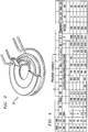
- Various acceptable sets of conditions are shown in the table of FIG. 4 , where it is to be understood that these values are exemplary only and many other combinations will provide the desired narrow reaction zone upstream of the plasma.
- the narrow deposition zone permits the deposition to be much more uniform along the entire length of the tube than the depositions achievable with conventional MCVD and PCVD processes.
- the process of the present invention allows for a higher yield of uniform quality optical fiber to be drawn from the preform created by the substrate tube.
- the inventive process also exhibits a higher deposition efficiency than other processes, leading to a further cost savings in terms of the expensive raw materials.
- Isothermal plasma has previously been used for deposition inside a substrate tube.
- most of these prior art methods used an atmospheric pressure plasma, rather than the low-pressure (sub-atmospheric) plasma (e.g., 10 Torr) used in accordance with the present invention.
- the homogeneously formed particulate will be deposited as soot, subsequently fused by the plasma.
- Such plasma deposition at atmospheric pressure will also occur over a broader zone, since the particles under the influence of the higher gas density will be swept down the substrate tube by the gas flow.
- These prior art processes use the heat from the plasma to stimulate the reaction and deposition of the soot, then subsequently sinter the deposited soot layer.
- the vaporization temperature for the substrate is substantially higher, and heating the substrate to greater than 1700°C does not present a problem.
- Low pressure RF plasma as used in the past was an argon plasma. Using the reported conditions, the deposition was described by the authors as being similar to that of microwave PCVD and that it occurred in the plasma without formation of particles.
- the inventive low pressure, isothermal plasma process apparently creates molten glass particles that are deposited on the substrate wall prior to entering the plasma (i.e., "upstream" of the plasma). No soot is created/deposited in the inventive process. Moreover, there is no evidence of additional deposition occurring in the plasma region; all deposition takes place in the narrow zone immediately upstream of the plasma. Also, the plasma is not used for any "fusing" operation in the method of the present invention. That is, since the deposited particles are glass particles and not soot, sintering is not required. In fact, achieving such fusion temperatures could be detrimental to the process.
- deposition on a planar surface can be similarly accomplished by creating the plasma in a low pressure chamber.
- the depositions may occur on materials other than silica.
- a translating apparatus or spinning substrate with a flowing reactant stream can be used to deposit a uniform glass film.
- the depositions may be formed along the outer surface of a core rod disposed in a similar low pressure environment.
- the scope of the present invention is not considered to be limited to depositions within the inner walls of a substrate tube.
Landscapes
- Chemical & Material Sciences (AREA)
- Engineering & Computer Science (AREA)
- Geochemistry & Mineralogy (AREA)
- Life Sciences & Earth Sciences (AREA)
- General Chemical & Material Sciences (AREA)
- General Life Sciences & Earth Sciences (AREA)
- Chemical Kinetics & Catalysis (AREA)
- Manufacturing & Machinery (AREA)
- Materials Engineering (AREA)
- Organic Chemistry (AREA)
- Physics & Mathematics (AREA)
- Plasma & Fusion (AREA)
- Manufacture, Treatment Of Glass Fibers (AREA)
- Chemical Vapour Deposition (AREA)
Description
- The present invention relates to a plasma technique for depositing material in a substrate tube and, more particularly, to an isothermal, low pressure process that results in creating an extremely narrow reaction zone in the tube within which a more uniform and efficient deposition will occur.
- Optical fiber typically contains a high-purity silica glass core optionally doped with a refractive index-raising element (such as germanium), an inner cladding of high-purity silica glass optionally doped with a refractive index-lowering element (such as fluorine), and an outer cladding of undoped silica glass. In some manufacturing processes, the preforms for making such fiber are fabricated by using a glass tube for the outer cladding (referred to as an overcladding tube), and separately forming a core rod containing the core and inner cladding material. The core rods are fabricated by any of a variety of vapor deposition methods known to those skilled in the art, including vapor axial deposition (VAD), outside vapor deposition (OVD), and modified chemical vapor deposition (MCVD). MCVD, for example, involves passing a high-purity gas, e.g., a mixture of gases containing silicon and germanium, through the interior of a silica tube (also referred to as a "substrate tube") while heating the outside of the tube with a traversing oxy-hydrogen torch. In the heated area of the tube, a gas phase reaction occurs that deposits particles on the tube wall. This deposit, which forms ahead of the torch (referred to as "downstream"), is sintered as the torch passes over it. The process is repeated in successive passes until the requisite quantity of silica and/or germanium-doped silica is deposited. Once deposition is complete, the body is heated to collapse the substrate tube and obtain a consolidated core rod in which the substrate tube constitutes the outer portion of the inner cladding material. To obtain a finished preform, the overcladding tube is typically placed over the core rod, and the components are heated and collapsed into the final preform structure.
- As an alternative to MCVD, a plasma chemical vapor deposition (PCVD) process may be used. In the PCVD method, the substrate tube passes through a microwave applicator (also referred to as an activator chamber, or activator head), which forms an electro-magnetic field around and inside the tube. A non-isothermal, low-pressure plasma is generated inside the tube by the interaction of the electro-magnetic field with the feed (e.g., SiCl4, GeCl4, and O2). Chemical reactions are then enabled to form glass particles that deposit themselves on the inside of the tube. An external heat source (such as a furnace) is required in PCVD to heat the substrate during deposition to ensure that the deposited glass is of a form that can be subsequently fused to clear glass. Once deposition is complete, the body is heated to collapse the substrate tube (in a manner similar to MCVD) and obtain a consolidated core rod in which the substrate tube constitutes the outer portion of the inner cladding material. To obtain a finished preform, an overcladding tube is typically placed over the core rod, and the components are heated and collapsed into the final preform structure.
- These current methods of providing deposition of the preform materials using MCVD or PCVD exhibit deposition problems resulting from the relatively long deposition zone widths inherent in these processes (i.e., the extent of the deposition along the tube at any given instant of time). In MCVD, glass precursor vapors are introduced through a seal into the end of a substrate tube of length generally between one and three meters. The vapors encounter a reaction zone and are converted to oxides that deposit as soot on the inner tube wall. The widths of these zones of deposition are generally wider than the reaction zones and can be as much as 10-30% of the overall substrate tube length. As a result, the deposited material at the ends of the tube sometimes exhibits a non-uniform thickness, thereby adversely affecting the overall preform. Further, when multi-component compositions are being deposited (such as germanium silicates), the deposited regions tend to be nonuniform in composition as a function of zone position, due to different reaction rates of the glass constituents.
- In PCVD, the reaction takes place within the created plasma region, the length of which is generally 10-20% of the overall substrate tube length. As in MCVD, there is a variation in reactivity within the plasma, resulting in variations in the thickness and/or composition of the reacted components. Therefore, the glass that is deposited on the inside of the substrate tube at any given time using a PCVD process can be non-uniform in terms of thickness and/or composition.
- Moreover, the deposited cores in preforms made by these processes may vary in diameter and optical properties along the deposited length, also affecting the quality of the resulting fiber. Further, in MCVD, the soot formed in the reaction zone is capable of traveling the length of the tube and can potentially deposit itself at any point along the tube, regardless of the reaction zone location, thus leading to a certain degree of unpredictability in the deposition process.
-
EP 0 005 963 A1 - HÜNLICH T et al. Fiber-Preform Fabrication Using Plasma Technology: A Review" Journal of Optical Communications 8 (1987) 4, 122-129 describes various well-known high and low pressure plasma processes for depositing silicon in a manner that allows for the fabrication of high quality, low loss optical fibers. Both inside and outside deposition processes are described. Section 2.2.3 on page 125 describes in general terms an ICPCVD process using an isothermal plasma.
- It is an object of the invention to improve the quality of materials deposited within substrate tubes.
- This object is achieved by a process of claim 1.
- The needs remaining in the prior art are addressed by the invention, which relates to a plasma technique for depositing material within a substrate tube and, more particularly, to an isothermal, low-pressure plasma process that results in creating a narrow reaction zone within which a more uniform and efficient deposition will occur.
- In accordance with the present invention, isothermal, low pressure plasma operating conditions have been found that generate a narrow deposition zone upstream of the plasma (i.e., a location between the introduction of the reactant materials and the plasma). These operating conditions depend upon a number of interacting parameters. In essence, the key objective is to provide sufficient energy density for the creation of a narrow reaction zone, while not exceeding a heat level that would otherwise vaporize the inner surface of the substrate tube.
- In some embodiments of the present invention, the exhaust end of the substrate tube is connected, through a vacuum system, to a scrubber apparatus for removal and neutralization of reaction by-products.
- It is an aspect of the present invention that the isothermal, low pressure deposition process is particularly well-suited for the manufacture of optical fiber core rods that require precision core profiles (such as, for example, multimode core rods), since the deposition occurs in a very narrow zone (generally about one centimeter or less), in very thin layers, and does not require sintering.
- Other and further aspects and advantages of the present invention will become apparent during the course of the following discussion and by reference to the accompanying drawings.
- Referring now to the drawings,
-
FIG. 1 illustrates an exemplary apparatus for performing the deposition process of the present invention; -
FIG. 2 is an isometric view of an exemplary concentrator coil that may be used as the resonant coil in the plasma-generating portion of the apparatus; -
FIGs. 3(a) and (b) provide a comparison between a non-isothermal plasma (FIG. 3(a) ) and an isothermal plasma (FIG. 3(b) ; and -
FIG. 4 is a table of various sets of operating parameters useful in forming an isothermal, low pressure deposition plasma in accordance with the present invention. -
FIG. 1 illustrates anexemplary apparatus 10 that may be used to practice the low pressure, isothermal deposition method of the present invention. As mentioned above and discussed in detail below, several operating parameters ofapparatus 10 are controlled to allow for the formation of an extremely narrow deposition zone immediately upstream of the created plasma. In accordance with one embodiment of the present invention, the deposition conditions are controlled such that the narrow deposition zone occupies about only 1% of the length of a conventional substrate tube (as opposed to the 10-30% values associated with the prior art MCVD and PCVD processes). More broadly, the particularly conditions utilized with the teachings of the present invention result in a narrow deposition zone of one centimeter or less. Asilica tube 12 is used inapparatus 10 as the substrate tube within which the deposition will occur, where the inner diameter (ID) and outer diameter (OD) oftube 12 are two of the operating parameters that are accounted for in developing the proper set of narrow zone deposition conditions, since the wall thickness also has an effect on the temperature of the inside wall and the reaction chemistry at the wall's surface. -
Apparatus 10 further comprises a chemical delivery system 14 to deliver one or more chemical reactants (such as GeCl4, SiCl4, C2F6 and O2) intosubstrate tube 12 through afirst seal 16 formed within a first end oftube 12. Although not shown inFIG. 1 (and not essential to the operation of the apparatus),substrate tube 12 is typically mounted in a glass working lathe that maintains the integrity offirst seal 16 while rotatingtube 12. The opposing end oftube 12 is coupled through asecond seal 18 to avacuum exhaust system 20. Advantageously,exhaust system 20 may be connected to ascrubber apparatus 22, which is used for removal and neutralization of any reaction by-products. In an embodiment wheresubstrate tube 12 is mounted in a rotating lathe,seals - As shown in
FIG. 1 , anisothermal plasma generator 30 is included inapparatus 10 and used to create a plasma of sufficient energy density withinsubstrate 12 to provide the desired chemical reaction(s) with the delivered material. In most cases,generator 30 is mounted on a movable table (not shown) such that it can be traversed parallel to the axis of the mounted substrate tube, indicated by the double-ended arrow inFIG. 1 .Isothermal plasma generator 30 comprises aresonant coil 32 that is positioned to surround a relatively short extent oftube 12, as shown inFIG. 1 . AnRF signal source 34 is coupled toresonant coil 32 and used to supply an RF signal thereto, thus creating the electro-magnetic field withintube 12. The combination of the incoming chemical reactants with the electro-magnetic field thus forms a plasma of an energy density sufficient to trigger the deposition of material on the inner surface oftube 12. - Although not necessary for the implementation of the process for all possible operating conditions the apparatus may also employ an external heating device (such as a furnace or linear burner) to control the temperature of the substrate tube during the deposition phase. The external heat assures that the deposited material adheres well to the substrate tube and avoids cracking of the material during deposition. As mentioned above, the thickness of the tube wall itself is one factor that is considered when determining if an external heating device is required.
- In accordance with the present invention, an "isothermal" plasma is generated, meaning that both the ions and electrons in the plasma are at roughly the same temperature. In contrast, conventional PCVD systems use a non-isothermal plasma, where the electrons have a much higher energy that the ions. Importantly, the use of an isothermal plasma in the arrangement of the present invention allows for the reaction and deposition to occur immediately "upstream" of the plasma, shown as
zone 40 inFIG. 1 . - As used throughout this discussion, the term "upstream" is considered to refer to that portion of the substrate tube between
first seal 16 and the created isothermal plasma. This particular upstream deposition mechanism results in the creation of molten glass particles (as opposed to soot) through homogeneous particle formation and growth, where these molten glass particles are then thermophoretically deposited upstream of the plasma, withinzone 40. That is, the deposition occurs prior to the reactants entering the plasma region. A narrow heat zone (within a few inches of the center of the plasma) provides a high concentration of heat for reaction and thermophoretic deposition while the plasma further downstream heats the tube wall to prepare it for the deposit, increasing the temperature on the side wall ofsubstrate tube 12. Thus, asplasma generator 30 traversestube 12, the heated zone "upstream" of the plasma is the area where deposition occurs. The temperature of the inside wall is sufficient to melt the glass particles into molten form as they adhere to the inside wall, thus forming a uniform glass film. Importantly, the parameters of the inventive deposition process are controlled such that the reaction zone is not heated to a temperature at which the substrate will begin to vaporize (or decompose) instead of melt. The use of a low pressure within this arrangement (i.e., less than atmospheric pressure, for example, about 10 Torr), in combination with the isothermal plasma, results in this deposition zone being extremely narrow (on the order of 1% of the tube length, generally about one centimeter or less), having a definite "edge" at the boundary with the plasma. The low pressure also helps to reduce the heat content of the very high temperature plasma so that the substrate and reactants are not vaporized. - In conventional RF plasma applications, it is typical to use a solenoid-shaped coil to induce the electro-magnetic field. In contrast, for the particular application of the present invention (i.e., isothermal, low pressure conditions), it has been found that a concentrator coil, i.e., a coil that shapes the field such that it is concentrated to a smaller volume, is of particular advantage. In one particular embodiment, a water-cooled
RF concentrator coil 32 may be used to shape the generated plasma field such that a lower power source may be used.FIG. 2 is a simplified, isometric view of one exemplary water-cooled concentrator coil that may be used inplasma generator 30 of the present invention. -
FIG. 3 contains a pair of photographs depicting the differences in plasma generation between a non-isothermal arrangement and an isothermal arrangement, where both are created at the same, low pressure using an RF source.FIG. 3(a) illustrates the generated non-isothermal plasma, which is shown as being rather expansive, spreading along a significant portion of the substrate length. In contrast,FIG. 3(b) illustrates the generated isothermal plasma, as used in the arrangement of the present invention. Clearly, the isothermal plasma is much more contained within the vicinity of the resonant coil, having well-defined boundaries, particularly on the upstream side. As mentioned above, it is the presence of this well-defined edge on the upstream side of the isothermal plasma that creates this very narrow transition region from "no plasma" to "plasma" where virtually all of the chemical reaction and deposition occurs (i.e.,zone 40 as shown inFIG. 1 ). The isothermal plasma basically acts as a thermophoretic "plug", forcing virtually all of the particulate to deposit upstream of the plasma. - Key to achieving this plasma condition is providing a sufficient energy density to create the narrow upstream deposition zone without providing so much heat that the inner wall of the substrate tube is vaporized. There is a broad range of isothermal plasma operating conditions that have been found to provide this narrow deposition zone. In particular, the "zone" is defined as that region of energy density upstream of the plasma sufficient to bring about the reaction of the precursors and assure that the deposited material is molten glass, not soot. Several interdependent factors are taken into consideration, including (but not necessarily limited to) plasma power, substrate tube internal pressure (sub-atmospheric pressure), substrate tube inner diameter, substrate tube wall thickness, substrate tube external heating, reactant composition, reactant flow rate, plasma traverse velocity, plasma traverse length, and plasma induction source. The intent in choice of conditions is to a sufficient energy density that transfers a limited amount of heat to the substrate tube, thus minimizing the possibility of vaporizing the substrate tube wall if the temperature is too high, and avoiding the formation of bubbles in the processed glass if the temperature is too low. Various acceptable sets of conditions are shown in the table of
FIG. 4 , where it is to be understood that these values are exemplary only and many other combinations will provide the desired narrow reaction zone upstream of the plasma. - It is significant that the narrow deposition zone permits the deposition to be much more uniform along the entire length of the tube than the depositions achievable with conventional MCVD and PCVD processes. As a result, the process of the present invention allows for a higher yield of uniform quality optical fiber to be drawn from the preform created by the substrate tube. The inventive process also exhibits a higher deposition efficiency than other processes, leading to a further cost savings in terms of the expensive raw materials.
- Isothermal plasma has previously been used for deposition inside a substrate tube. However, most of these prior art methods used an atmospheric pressure plasma, rather than the low-pressure (sub-atmospheric) plasma (e.g., 10 Torr) used in accordance with the present invention. At atmospheric pressure, the homogeneously formed particulate will be deposited as soot, subsequently fused by the plasma. Such plasma deposition at atmospheric pressure will also occur over a broader zone, since the particles under the influence of the higher gas density will be swept down the substrate tube by the gas flow. These prior art processes use the heat from the plasma to stimulate the reaction and deposition of the soot, then subsequently sinter the deposited soot layer. At atmospheric pressure, the vaporization temperature for the substrate is substantially higher, and heating the substrate to greater than 1700°C does not present a problem. Low pressure RF plasma as used in the past was an argon plasma. Using the reported conditions, the deposition was described by the authors as being similar to that of microwave PCVD and that it occurred in the plasma without formation of particles.
- An important distinction is that the inventive low pressure, isothermal plasma process apparently creates molten glass particles that are deposited on the substrate wall prior to entering the plasma (i.e., "upstream" of the plasma). No soot is created/deposited in the inventive process. Moreover, there is no evidence of additional deposition occurring in the plasma region; all deposition takes place in the narrow zone immediately upstream of the plasma. Also, the plasma is not used for any "fusing" operation in the method of the present invention. That is, since the deposited particles are glass particles and not soot, sintering is not required. In fact, achieving such fusion temperatures could be detrimental to the process.
- While the above description has described a deposition process within a substrate tube, it is to be understood that the inventive features associated with creating a narrow deposition zone and eliminating a sintering process step may also be utilized with various other deposition schemes. For example, deposition on a planar surface (such as a silica wafer) can be similarly accomplished by creating the plasma in a low pressure chamber. Indeed, the depositions may occur on materials other than silica. A translating apparatus or spinning substrate with a flowing reactant stream can be used to deposit a uniform glass film. Alternatively, the depositions may be formed along the outer surface of a core rod disposed in a similar low pressure environment. Thus, the scope of the present invention is not considered to be limited to depositions within the inner walls of a substrate tube.
Claims (6)
- A process of depositing a material on an inner wall of a substrate tube (12), the process comprising the steps of:disposing a silica substrate tube (12) within a resonant coil (32) of a plasma generator (30);presenting at least one chemical reactant through a first, delivery end of the substrate tube (12);maintaining internal pressure within the substrate tube (12) to be less than atmospheric pressure; andenergizing the resonant coil (32);characterized in thatthe resonant coil (32) is energized to create an isothermal plasma of ions and electrons at the same temperature and heating the inner wall of the substrate tube (12); andthe process comprises depositing reactant products of the at least one chemical reactant on the inner wall of the substrate tube (12) within only a narrow zone upstream of the created isothermal plasma without any deposition occurring within the isothermal plasma and the narrow zone being no greater than 1% of the length of the substrate tube (12).
- The process as defined in claim 1 wherein the deposition conditions are controlled such that the narrow zone is confined to an area of one centimeter or less in length.
- The process as defined in claim 1 wherein the process further comprises the step of:evacuating reaction by-products through a vacuum system coupled to a second, exhaust end of the substrate tube (12).
- The process as defined in claim 3 wherein the process further comprises the step of:scrubbing the evacuated reaction by-products to remove and neutralize the reaction by-products.
- The process as defined in claim 1 wherein in performing the deposition, the narrow zone length is controlled by one or more parameters selected from the group consisting of: plasma generator power, substrate tube internal pressure, substrate tube inner diameter, substrate tube wall thickness, substrate tube external heating, chemical reactant composition, chemical reactant flow rate, isothermal plasma traverse velocity, isothermal plasma traverse length, and resonant coil (32) configuration.
- The process as defined in claim 1 wherein the process comprises the further steps of forming an optical fiber core rod by:heating the substrate tube (12); andcollapsing the heated substrate tube (12) to form the optical fiber core rod.
Applications Claiming Priority (1)
| Application Number | Priority Date | Filing Date | Title |
|---|---|---|---|
| US12/001,174 US8252387B2 (en) | 2007-12-10 | 2007-12-10 | Method of fabricating optical fiber using an isothermal, low pressure plasma deposition technique |
Publications (4)
| Publication Number | Publication Date |
|---|---|
| EP2070885A2 EP2070885A2 (en) | 2009-06-17 |
| EP2070885A3 EP2070885A3 (en) | 2012-09-19 |
| EP2070885B1 true EP2070885B1 (en) | 2017-02-15 |
| EP2070885B8 EP2070885B8 (en) | 2017-05-24 |
Family
ID=40451185
Family Applications (1)
| Application Number | Title | Priority Date | Filing Date |
|---|---|---|---|
| EP08021208.7A Ceased EP2070885B8 (en) | 2007-12-10 | 2008-12-05 | Method of fabricating optical fiber using an isothermal, low pressure plasma deposition technique |
Country Status (4)
| Country | Link |
|---|---|
| US (2) | US8252387B2 (en) |
| EP (1) | EP2070885B8 (en) |
| JP (1) | JP5519145B2 (en) |
| CN (1) | CN101580341B (en) |
Families Citing this family (4)
| Publication number | Priority date | Publication date | Assignee | Title |
|---|---|---|---|---|
| US8252387B2 (en) * | 2007-12-10 | 2012-08-28 | Ofs Fitel, Llc | Method of fabricating optical fiber using an isothermal, low pressure plasma deposition technique |
| US9002162B2 (en) * | 2013-03-15 | 2015-04-07 | Ofs Fitel, Llc | Large core multimode optical fibers |
| US20160023939A1 (en) * | 2014-07-24 | 2016-01-28 | Ofs Fitel, Llc | Isothermal plasma cvd system for reduced taper in optical fiber preforms |
| CN110629200B (en) * | 2019-09-20 | 2020-04-10 | 理想晶延半导体设备(上海)有限公司 | Semiconductor processing equipment |
Family Cites Families (34)
| Publication number | Priority date | Publication date | Assignee | Title |
|---|---|---|---|---|
| DE2444100C3 (en) * | 1974-09-14 | 1979-04-12 | Philips Patentverwaltung Gmbh, 2000 Hamburg | Process for the production of internally coated glass tubes for drawing optical fibers |
| US4145456A (en) * | 1974-09-14 | 1979-03-20 | Dieter Kuppers | Method of producing internally coated glass tubes for the drawing of fibre optic light conductors |
| GB1578826A (en) * | 1976-03-25 | 1980-11-12 | Western Electric Co | Methods for fabricating optical fibre preforms |
| JPS5430852A (en) * | 1977-08-11 | 1979-03-07 | Nippon Telegr & Teleph Corp <Ntt> | Production of glass fiber for optical communication |
| GB1603949A (en) * | 1978-05-30 | 1981-12-02 | Standard Telephones Cables Ltd | Plasma deposit |
| JPS5510468A (en) * | 1978-07-10 | 1980-01-24 | Nippon Telegr & Teleph Corp <Ntt> | Production of glass fiber for light communication |
| DE2950446A1 (en) * | 1978-08-18 | 1980-12-04 | Western Electric Co | The fabrication of optical fibers utilizing thermophoretic deposition of glass precursor particulates |
| DE2929166A1 (en) * | 1979-07-19 | 1981-01-29 | Philips Patentverwaltung | METHOD FOR THE PRODUCTION OF OPTICAL FIBERS |
| US4262035A (en) * | 1980-03-07 | 1981-04-14 | Bell Telephone Laboratories, Incorporated | Modified chemical vapor deposition of an optical fiber using an rf plasma |
| US4331462A (en) * | 1980-04-25 | 1982-05-25 | Bell Telephone Laboratories, Incorporated | Optical fiber fabrication by a plasma generator |
| NL8102149A (en) * | 1981-05-01 | 1982-12-01 | Philips Nv | METHOD AND APPARATUS FOR INTERNAL COVERING OF A TUBE BY REACTIVE SEPARATION FROM A GAS MIX INFLUENCED BY A PLASMA |
| DE3205345A1 (en) * | 1982-02-15 | 1983-09-01 | Philips Patentverwaltung Gmbh, 2000 Hamburg | "METHOD FOR THE PRODUCTION OF FLUOREDOTED LIGHT-CONDUCTING FIBERS" |
| US4507135A (en) | 1982-08-02 | 1985-03-26 | Corning Glass Works | Method of making optical fiber preform |
| NL8402225A (en) * | 1984-07-13 | 1986-02-03 | Philips Nv | METHOD FOR MANUFACTURING SOLID GLASS PREFORMS FROM HOLLOW FORMS |
| US4727236A (en) * | 1986-05-27 | 1988-02-23 | The United States Of America As Represented By The Department Of Energy | Combination induction plasma tube and current concentrator for introducing a sample into a plasma |
| NL9100335A (en) * | 1991-02-26 | 1992-09-16 | Philips Nv | METHOD FOR MANUFACTURING TUBE GLASS. |
| US5211731A (en) * | 1991-06-27 | 1993-05-18 | The United States Of Americas As Represented By The Secretary Of The Navy | Plasma chemical vapor deposition of halide glasses |
| US5397372A (en) * | 1993-11-30 | 1995-03-14 | At&T Corp. | MCVD method of making a low OH fiber preform with a hydrogen-free heat source |
| DE4444577B4 (en) * | 1993-12-15 | 2005-02-10 | Bridgestone Corp. | Method for producing an optical waveguide |
| US5597438A (en) * | 1995-09-14 | 1997-01-28 | Siemens Aktiengesellschaft | Etch chamber having three independently controlled electrodes |
| US6253580B1 (en) * | 1997-12-19 | 2001-07-03 | Fibercore, Inc. | Method of making a tubular member for optical fiber production using plasma outside vapor deposition |
| US6105396A (en) * | 1998-07-14 | 2000-08-22 | Lucent Technologies Inc. | Method of making a large MCVD single mode fiber preform by varying internal pressure to control preform straightness |
| US6380680B1 (en) * | 1998-10-02 | 2002-04-30 | Federal-Mogul World Wide, Inc. | Electrodeless gas discharge lamp assembly with flux concentrator |
| US6305195B1 (en) * | 1999-05-27 | 2001-10-23 | Agere Systems Guardian Corp. | Process for fabricating silica article involving joining of discrete bodies |
| US6793775B2 (en) * | 2001-03-13 | 2004-09-21 | Mikhail I. Gouskov | Multiple torch—multiple target method and apparatus for plasma outside chemical vapor deposition |
| JP4610126B2 (en) * | 2001-06-14 | 2011-01-12 | 株式会社神戸製鋼所 | Plasma CVD equipment |
| NL1020358C2 (en) * | 2002-04-10 | 2003-10-13 | Draka Fibre Technology Bv | Method and device for manufacturing optical preforms, as well as the optical fibers obtained therewith. |
| JP2004203682A (en) * | 2002-12-25 | 2004-07-22 | Sumitomo Electric Ind Ltd | Method and apparatus for manufacturing optical fiber preform |
| US20050022561A1 (en) * | 2003-08-01 | 2005-02-03 | Guskov Michael I. | Ring plasma jet method and apparatus for making an optical fiber preform |
| US7793612B2 (en) * | 2003-08-01 | 2010-09-14 | Silica Tech, Llc | Ring plasma jet method and apparatus for making an optical fiber preform |
| US20050284184A1 (en) * | 2004-06-29 | 2005-12-29 | Grant Baynham | Methods for optical fiber manufacture |
| US8252387B2 (en) * | 2007-12-10 | 2012-08-28 | Ofs Fitel, Llc | Method of fabricating optical fiber using an isothermal, low pressure plasma deposition technique |
| US8857372B2 (en) * | 2007-12-10 | 2014-10-14 | Ofs Fitel, Llc | Method of fabricating optical fiber using an isothermal, low pressure plasma deposition technique |
| US9002162B2 (en) * | 2013-03-15 | 2015-04-07 | Ofs Fitel, Llc | Large core multimode optical fibers |
-
2007
- 2007-12-10 US US12/001,174 patent/US8252387B2/en active Active
-
2008
- 2008-12-05 EP EP08021208.7A patent/EP2070885B8/en not_active Ceased
- 2008-12-09 CN CN200810183834.5A patent/CN101580341B/en not_active Expired - Fee Related
- 2008-12-10 JP JP2008313821A patent/JP5519145B2/en not_active Expired - Fee Related
-
2012
- 2012-07-26 US US13/559,016 patent/US20120285202A1/en not_active Abandoned
Non-Patent Citations (1)
| Title |
|---|
| None * |
Also Published As
| Publication number | Publication date |
|---|---|
| EP2070885B8 (en) | 2017-05-24 |
| US8252387B2 (en) | 2012-08-28 |
| CN101580341A (en) | 2009-11-18 |
| US20090148613A1 (en) | 2009-06-11 |
| EP2070885A2 (en) | 2009-06-17 |
| CN101580341B (en) | 2013-08-14 |
| US20120285202A1 (en) | 2012-11-15 |
| EP2070885A3 (en) | 2012-09-19 |
| JP5519145B2 (en) | 2014-06-11 |
| JP2009137837A (en) | 2009-06-25 |
Similar Documents
| Publication | Publication Date | Title |
|---|---|---|
| US4262035A (en) | Modified chemical vapor deposition of an optical fiber using an rf plasma | |
| CA1165551A (en) | Optical fiber fabrication and resulting product | |
| US4125389A (en) | Method for manufacturing an optical fibre with plasma activated deposition in a tube | |
| EP0067050A1 (en) | Method of forming an optical waveguide fiber | |
| GB1567876A (en) | Method of and apparatus for manufacturing a fused tube for forming into an optical fibre with plasma activated deposition in a tube | |
| EP2070885B1 (en) | Method of fabricating optical fiber using an isothermal, low pressure plasma depostion technique | |
| US4302230A (en) | High rate optical fiber fabrication process using thermophoretically enhanced particle deposition | |
| US8857372B2 (en) | Method of fabricating optical fiber using an isothermal, low pressure plasma deposition technique | |
| JP5683161B2 (en) | Manufacturing method and manufacturing apparatus for primary preform for optical fiber | |
| RU2236386C2 (en) | Method of manufacturing optic fiber intermediate product | |
| JP6214766B2 (en) | Plasma deposition process with removal of substrate tube | |
| US7003984B2 (en) | Hybrid manufacturing process for optical fibers | |
| EP0072069B1 (en) | Method of producing preforms for drawing optical fibres and apparatus for the continuous production of optical fibres | |
| CN116892018A (en) | PCVD deposition process for manufacturing primary preforms and method of forming optical fibers from such preforms | |
| EP2158169B1 (en) | Method for continuous or batch optical fiber preform and optical fiber production | |
| JP2695644B2 (en) | Optical fiber manufacturing method | |
| GB1574115A (en) | Optical fibre manufacture | |
| US9643879B2 (en) | Method for manufacturing a precursor for a primary preform for optical fibres by a plasma deposition process | |
| KR20040014855A (en) | a manufacturing method and a manufacturing device by Outside Vapor Deposition | |
| US9266767B2 (en) | PCVD method for manufacturing a primary preform for optical fibers | |
| US20240134113A1 (en) | Controlling refractive index profile during fiber preform manufacturing | |
| CN117902824A (en) | Controlling refractive index profile in optical fiber preform fabrication | |
| JP2004210561A (en) | Manufacturing method of optical fiber preform |
Legal Events
| Date | Code | Title | Description |
|---|---|---|---|
| PUAI | Public reference made under article 153(3) epc to a published international application that has entered the european phase |
Free format text: ORIGINAL CODE: 0009012 |
|
| AK | Designated contracting states |
Kind code of ref document: A2 Designated state(s): AT BE BG CH CY CZ DE DK EE ES FI FR GB GR HR HU IE IS IT LI LT LU LV MC MT NL NO PL PT RO SE SI SK TR |
|
| AX | Request for extension of the european patent |
Extension state: AL BA MK RS |
|
| PUAL | Search report despatched |
Free format text: ORIGINAL CODE: 0009013 |
|
| RIC1 | Information provided on ipc code assigned before grant |
Ipc: C03B 37/018 20060101AFI20120809BHEP |
|
| AK | Designated contracting states |
Kind code of ref document: A3 Designated state(s): AT BE BG CH CY CZ DE DK EE ES FI FR GB GR HR HU IE IS IT LI LT LU LV MC MT NL NO PL PT RO SE SI SK TR |
|
| AX | Request for extension of the european patent |
Extension state: AL BA MK RS |
|
| 17P | Request for examination filed |
Effective date: 20130319 |
|
| AKX | Designation fees paid |
Designated state(s): DE FR GB NL |
|
| 17Q | First examination report despatched |
Effective date: 20150227 |
|
| GRAP | Despatch of communication of intention to grant a patent |
Free format text: ORIGINAL CODE: EPIDOSNIGR1 |
|
| INTG | Intention to grant announced |
Effective date: 20160816 |
|
| GRAS | Grant fee paid |
Free format text: ORIGINAL CODE: EPIDOSNIGR3 |
|
| GRAA | (expected) grant |
Free format text: ORIGINAL CODE: 0009210 |
|
| AK | Designated contracting states |
Kind code of ref document: B1 Designated state(s): DE FR GB NL |
|
| REG | Reference to a national code |
Ref country code: GB Ref legal event code: FG4D |
|
| GRAT | Correction requested after decision to grant or after decision to maintain patent in amended form |
Free format text: ORIGINAL CODE: EPIDOSNCDEC |
|
| REG | Reference to a national code |
Ref country code: DE Ref legal event code: R096 Ref document number: 602008048741 Country of ref document: DE |
|
| REG | Reference to a national code |
Ref country code: NL Ref legal event code: FP |
|
| REG | Reference to a national code |
Ref country code: DE Ref legal event code: R097 Ref document number: 602008048741 Country of ref document: DE |
|
| PLBE | No opposition filed within time limit |
Free format text: ORIGINAL CODE: 0009261 |
|
| STAA | Information on the status of an ep patent application or granted ep patent |
Free format text: STATUS: NO OPPOSITION FILED WITHIN TIME LIMIT |
|
| REG | Reference to a national code |
Ref country code: FR Ref legal event code: PLFP Year of fee payment: 10 |
|
| 26N | No opposition filed |
Effective date: 20171116 |
|
| PGFP | Annual fee paid to national office [announced via postgrant information from national office to epo] |
Ref country code: GB Payment date: 20201228 Year of fee payment: 13 Ref country code: FR Payment date: 20201227 Year of fee payment: 13 |
|
| PGFP | Annual fee paid to national office [announced via postgrant information from national office to epo] |
Ref country code: NL Payment date: 20201226 Year of fee payment: 13 |
|
| PGFP | Annual fee paid to national office [announced via postgrant information from national office to epo] |
Ref country code: DE Payment date: 20201229 Year of fee payment: 13 |
|
| REG | Reference to a national code |
Ref country code: DE Ref legal event code: R119 Ref document number: 602008048741 Country of ref document: DE |
|
| REG | Reference to a national code |
Ref country code: NL Ref legal event code: MM Effective date: 20220101 |
|
| GBPC | Gb: european patent ceased through non-payment of renewal fee |
Effective date: 20211205 |
|
| PG25 | Lapsed in a contracting state [announced via postgrant information from national office to epo] |
Ref country code: NL Free format text: LAPSE BECAUSE OF NON-PAYMENT OF DUE FEES Effective date: 20220101 |
|
| PG25 | Lapsed in a contracting state [announced via postgrant information from national office to epo] |
Ref country code: GB Free format text: LAPSE BECAUSE OF NON-PAYMENT OF DUE FEES Effective date: 20211205 Ref country code: DE Free format text: LAPSE BECAUSE OF NON-PAYMENT OF DUE FEES Effective date: 20220701 |
|
| PG25 | Lapsed in a contracting state [announced via postgrant information from national office to epo] |
Ref country code: FR Free format text: LAPSE BECAUSE OF NON-PAYMENT OF DUE FEES Effective date: 20211231 |