EP2070573A1 - Gas removal device - Google Patents
Gas removal device Download PDFInfo
- Publication number
- EP2070573A1 EP2070573A1 EP07807571A EP07807571A EP2070573A1 EP 2070573 A1 EP2070573 A1 EP 2070573A1 EP 07807571 A EP07807571 A EP 07807571A EP 07807571 A EP07807571 A EP 07807571A EP 2070573 A1 EP2070573 A1 EP 2070573A1
- Authority
- EP
- European Patent Office
- Prior art keywords
- gas
- tube bundle
- removal device
- inlet
- tying
- Prior art date
- Legal status (The legal status is an assumption and is not a legal conclusion. Google has not performed a legal analysis and makes no representation as to the accuracy of the status listed.)
- Granted
Links
Images





Classifications
-
- B—PERFORMING OPERATIONS; TRANSPORTING
- B01—PHYSICAL OR CHEMICAL PROCESSES OR APPARATUS IN GENERAL
- B01D—SEPARATION
- B01D19/00—Degasification of liquids
-
- B—PERFORMING OPERATIONS; TRANSPORTING
- B01—PHYSICAL OR CHEMICAL PROCESSES OR APPARATUS IN GENERAL
- B01D—SEPARATION
- B01D53/00—Separation of gases or vapours; Recovering vapours of volatile solvents from gases; Chemical or biological purification of waste gases, e.g. engine exhaust gases, smoke, fumes, flue gases, aerosols
- B01D53/22—Separation of gases or vapours; Recovering vapours of volatile solvents from gases; Chemical or biological purification of waste gases, e.g. engine exhaust gases, smoke, fumes, flue gases, aerosols by diffusion
-
- B—PERFORMING OPERATIONS; TRANSPORTING
- B01—PHYSICAL OR CHEMICAL PROCESSES OR APPARATUS IN GENERAL
- B01D—SEPARATION
- B01D19/00—Degasification of liquids
- B01D19/0031—Degasification of liquids by filtration
-
- B—PERFORMING OPERATIONS; TRANSPORTING
- B01—PHYSICAL OR CHEMICAL PROCESSES OR APPARATUS IN GENERAL
- B01D—SEPARATION
- B01D61/00—Processes of separation using semi-permeable membranes, e.g. dialysis, osmosis or ultrafiltration; Apparatus, accessories or auxiliary operations specially adapted therefor
-
- B—PERFORMING OPERATIONS; TRANSPORTING
- B01—PHYSICAL OR CHEMICAL PROCESSES OR APPARATUS IN GENERAL
- B01D—SEPARATION
- B01D63/00—Apparatus in general for separation processes using semi-permeable membranes
- B01D63/02—Hollow fibre modules
- B01D63/024—Hollow fibre modules with a single potted end
-
- B—PERFORMING OPERATIONS; TRANSPORTING
- B01—PHYSICAL OR CHEMICAL PROCESSES OR APPARATUS IN GENERAL
- B01D—SEPARATION
- B01D63/00—Apparatus in general for separation processes using semi-permeable membranes
- B01D63/02—Hollow fibre modules
- B01D63/025—Bobbin units
-
- B—PERFORMING OPERATIONS; TRANSPORTING
- B01—PHYSICAL OR CHEMICAL PROCESSES OR APPARATUS IN GENERAL
- B01D—SEPARATION
- B01D71/00—Semi-permeable membranes for separation processes or apparatus characterised by the material; Manufacturing processes specially adapted therefor
- B01D71/06—Organic material
- B01D71/30—Polyalkenyl halides
- B01D71/32—Polyalkenyl halides containing fluorine atoms
- B01D71/36—Polytetrafluoroethylene
-
- B—PERFORMING OPERATIONS; TRANSPORTING
- B01—PHYSICAL OR CHEMICAL PROCESSES OR APPARATUS IN GENERAL
- B01D—SEPARATION
- B01D2313/00—Details relating to membrane modules or apparatus
- B01D2313/06—External membrane module supporting or fixing means
-
- B—PERFORMING OPERATIONS; TRANSPORTING
- B01—PHYSICAL OR CHEMICAL PROCESSES OR APPARATUS IN GENERAL
- B01D—SEPARATION
- B01D2313/00—Details relating to membrane modules or apparatus
- B01D2313/12—Specific discharge elements
-
- B—PERFORMING OPERATIONS; TRANSPORTING
- B01—PHYSICAL OR CHEMICAL PROCESSES OR APPARATUS IN GENERAL
- B01D—SEPARATION
- B01D2313/00—Details relating to membrane modules or apparatus
- B01D2313/20—Specific housing
- B01D2313/205—Specific housing characterised by the shape
-
- B—PERFORMING OPERATIONS; TRANSPORTING
- B01—PHYSICAL OR CHEMICAL PROCESSES OR APPARATUS IN GENERAL
- B01D—SEPARATION
- B01D2313/00—Details relating to membrane modules or apparatus
- B01D2313/21—Specific headers, end caps
Definitions
- the present invention relates to a gas removal device for removing gases from a liquid.
- a dissolved gas in a liquid may cause corrosion of tubes through which a liquid flows, decrease in heat exchanger effectiveness and pressure due to bubble generation, and uneven application of a liquid due to generated bubbles.
- degassing is required depending on the method and purpose of using a liquid.
- a gas removal device disclosed in JP 11-333206 A can be used for degassing a liquid (see Fig. 9 ).
- a gas removal device 101 shown in Fig. 9 a gas-permeable tube 103 is accommodated in a decompression chamber 102 with an inlet 111 and an outlet 112 through which the liquid to be degassed flows in and out.
- One end of the gas-permeable tube 103 is connected to the inlet 111 and another end is connected to the outlet 112.
- a vacuum suction pipe 104 reaching a bottom portion in the decompression chamber 102 is attached to the decompression chamber 102.
- the vacuum suction pipe 104 is connected to a vacuum suction port 113 of the decompression chamber 102.
- the liquid to be degassed is allowed to enter from the inlet 111 and flow through the gas-permeable tube 103, and an interior of the decompression chamber 102 is decompressed by a decompression device connected to the vacuum suction port 113.
- the liquid can be degassed.
- thin gas-permeable tubes are used in many cases so that they can contact with the liquid in a larger area and enhance the degassing performance.
- the thin gas-permeable tubes buckle sometimes when they are bent to be accommodated in the decompression chamber. In the gas-permeable tubes thus buckled, the flow resistance of the liquid to be degassed increases, and the gas removal device cannot exert its degassing performance sufficiently.
- the present invention is intended to provide a gas removal device in which the buckling of the gas-permeable tubes is prevented, and that exerts high degassing performance.
- the present invention provides a gas removal device including a decompression chamber with an inlet and an outlet through which a liquid to be degassed flows in and out, and a degassing element that is accommodated in the decompression chamber while having one end connected to the inlet and another end connected to the outlet, and that allows the liquid to be degassed entering into the inlet to pass through the degassing element.
- the degassing element includes a tube bundle composed of a plurality of flexible gas-permeable tubes, and a tying member that ties the plurality of gas-permeable tubes to form the tube bundle.
- the degassing element is accommodated in the decompression chamber in such a manner that at least a part of the tube bundle makes a bent portion formed by bending the tube bundle.
- the tying member is disposed on at least a part of the bent portion.
- the plurality of gas-permeable tubes is tied by the tying member to make the tube bundle.
- the tube bundle is bent in such a manner that a portion tied by the tying member is included in the bent portion.
- bending stress is generated in the gas-permeable tubes.
- the gas-permeable tubes tend to change their form into one that can alleviate the stress, but such a change cannot be made easily because a tying force of the tying member is acting on them. As a result, the occurrence of buckling is prevented.
- the liquid to be degassed circulates smoothly in the gas-permeable tubes that are not buckled, and thereby a gas removal device exerting high degassing performance can be realized.
- the present invention provides a gas removal device including a decompression chamber with an inlet and an outlet through which a liquid to be degassed flows in and out, and a degassing element that is accommodated in the decompression chamber while having one end connected to the inlet and another end connected to the outlet, and that allows the liquid to be degassed entering into the inlet to pass through the degassing element.
- the degassing element includes a tube bundle composed of a plurality of gas-permeable tubes, and a tying member winding spirally around the tube bundle to tie the plurality of gas-permeable tubes. At least a part of the tube bundle wound by the tying member is bent. The same effect can be obtained by such a configuration.
- Fig. 1 shows a gas removal device of Embodiment 1 of the present invention.
- the gas removal device 1 includes a decompression chamber 2.
- the decompression chamber 2 includes an inlet 11 and an outlet 12 through which a liquid to be degassed circulates, and a vacuum suction port 13 to be connected to a decompression device.
- the decompression chamber 2 has a cover 21, and a chamber main body 22 with a tubular shape.
- the chamber main body 22 has a bottom portion 23 and an opening portion 24.
- the inlet 11 and the outlet 12 are provided at the cover 21.
- the vacuum suction port 13 is provided at a side part 25 of the chamber main body 22.
- the cover 21 is fixed to the opening portion 24 of the chamber main body 22 in such a manner that airtightness in the decompression chamber 2 is maintained.
- a degassing element 5 is disposed in the decompression chamber 2. The degassing element 5 has an end connected to the inlet 11 and another end connected to the outlet 12.
- the degassing element 5 has a tube bundle 15 composed of a plurality of flexible gas-permeable tubes 151, tubular adapters 141 and 142, and tying members 16 tying the gas-permeable tubes 151.
- the adapters 141 and 142 include the inlet side adapter 141 attached to one end of the tube bundle 15 and connected to the inlet 11 of the decompression chamber 2, and the outlet side adapter 142 attached to another end of the tube bundle 15 and connected to the outlet 12 of the decompression chamber 2.
- the liquid to be degassed that has flowed into the inlet 11 via the inlet side adapter 141 circulates through the degassing element 5, that is, circulates through the gas-permeable tubes 151, and then flows out from the outlet 12 via the outlet side adapter 142.
- the degassing element 5 is accommodated in the decompression chamber 2 while the tube bundle 15 is bent in a shape of coil with multiple turns.
- a bent portion BP is formed by bending a part of the tube bundle 15 in a circular shape, and the tying members 16 each are disposed at plural points in the circular bent portion BP.
- the tying members 16 winding around the tube bundle 15 play a role of tying the gas-permeable tubes 151 into one bundle and maintaining the form of the tube bundle 15, as well as a role of preventing each of the gas-permeable tubes 151 from buckling when the tube bundle 15 is bent.
- the tube bundle 15 is bent in a shape of coil with multiple turns to form the bent portion BP as shown in Fig. 1 , bending stress is generated in the gas-permeable tubes 151.
- the form of the gas-permeable tubes 151 tends to change into one that can alleviate the stress.
- the tube bundle 15 is bent in such a manner that portions tied by the tying members 16 are included in the bent portion BP, the form of the gas-permeable tubes 151 is not changed easily. As a result, the occurrence of buckling is prevented. Disposing the tying members 16 on the bent portion BP at a predetermined interval allows the tying force to act evenly on the gas-permeable tubes 151 in a longitudinal direction. Thus, an enhanced effect of preventing buckling can be expected.
- the gas-permeable tubes 151 and 151 adjacent to each other are not bonded mutually between the inlet side adapter 141 and the outlet side adapter 142. More specifically, the gas-permeable tubes 151 and 151 are bonded (welded, to be specific) to each other only at both ends connected to the adapters 141 and 142. Since the tying force that the tying members 16 exert on the gas-permeable tubes 151 is not so large, the gas-permeable tubes 151 can move back and forth in the longitudinal direction. The tying members16 do not cover the gas-permeable tubes 151 entirely, and they are disposed along the longitudinal direction at a constant interval.
- tying the gas-permeable tubes 151 into one bundle improves the workability at the time of placing the degassing element 5 in the decompression chamber 2.
- Use of the tying members 16 easily prevents the gas-permeable tubes 151 from being loose. This makes it unnecessary to bond the gas-permeable tubes 151 and 151 together by using an adhesive or by performing thermal welding. Since a gap can be created between the gas-permeable tubes 151 and 151, the degassing performance of the degassing element 5 is expected to be enhanced.
- a string, a tube, a chain, and a film can be used, for example. Particularly, a thin film is preferable.
- the tying member 16 is a film, it winds around the tube bundle 15, and thereby it can tie the plurality of gas-permeable tubes 151 in such a manner that it wraps them. Then, the tying force exerted by the tying member 16 acts on the gas-permeable tubes 151 in plane, and thereby an excellent effect of preventing buckling can be obtained.
- the film used as the tying member 16 preferably has gas permeability.
- Using the gas-permeable film as the tying member 16 makes it possible to tie the gas-permeable tubes 151 almost without deteriorating the gas permeability of the gas-permeable tubes 151.
- Specific examples of the gas-permeable film include a porous film, and a laminated film obtained by stacking a reinforcement material on the porous film.
- the reinforcing material preferably has gas permeability greater than that of the porous film.
- a woven fabric, a nonwoven fabric, a mesh, a net, a sponge, a foam, a foamed material, and a porous material, these made of resin or metal, can be used as the reinforcement material.
- porous film suitable for the tying member 16 examples include a porous film made of fluororesin, such as polytetrafluoroethylene (PTFE), tetrafluoroethylene-perfluoroalkyl vinyl ether copolymer, ethylene-tetrafluoroethylene copolymer, and polychlorotrifluoroethylene, as well as a porous film made of polyolefin, such as polyethylene and polypropylene.
- PTFE polytetrafluoroethylene
- tetrafluoroethylene-perfluoroalkyl vinyl ether copolymer ethylene-tetrafluoroethylene copolymer
- polychlorotrifluoroethylene ethylene
- the porous film made of polytetrafluoroethylene is preferable because it has excellent gas permeability and chemical resistance.
- the tying member 16 may be of a strip-like shape. As shown in the cross-sectional view of Fig. 3 , both ends of the tying member 16 tying the gas-permeable tubes 151 are fixed to each other by an adhesive or thermal welding. Or the tying member 16 partially may be fixed to the tube bundle 15 using an adhesive etc. to prevent positional deviation of the tying member 16.
- the gas-permeable tubes 151 are tied by the tying members 16 at a plurality of points along the longitudinal direction. When thus configured, the gas-permeable tubes 151 can be tied more reliably. Moreover, appropriately adjusting the interval at which the tying members 16 are disposed can prevent the gas permeability of the gas-permeable tubes 151 from being deteriorated.
- Both of the cover 21 and the chamber main body 22 of the decompression chamber 2 are obtained by molding metal, glass, or plastic into a specific shape.
- metal stainless steel is preferable because of its excellent chemical resistance.
- plastic fluororesin and polyolefin can be used.
- the decompression chamber 2 desirably is made of metal.
- a tube commonly used in gas removal devices may be used as the gas-permeable tubes 151.
- a tube made of fluororesin such as polytetrafluoroethylene (PTFE), tetrafluoroethylene-perfluoroalkyl vinyl ether copolymer, ethylene-tetrafluoroethylene copolymer, and polychlorotrifluoroethylene, or a tube made of polyolefin, such as polyethylene and polypropylene.
- PTFE polytetrafluoroethylene
- tetrafluoroethylene-perfluoroalkyl vinyl ether copolymer ethylene-tetrafluoroethylene copolymer
- polychlorotrifluoroethylene or a tube made of polyolefin, such as polyethylene and polypropylene.
- thin hollow fibers preferably are used as the gas-permeable tubes 151 as shown in Fig. 3 .
- an inner diameter of one hollow fiber is in a range of about several tens of
- the tube bundle 15 is connected to the outlet 11 and the inlet 12 via the adapters 141 and 142.
- An adapter with a structure as shown in Fig. 4 can be employed as the adapters 141 and 142.
- the adapters 141 and 142 each include a wedge 52, a cap nut 51, and a mouth piece fitting 55 so as to be fixed to the end of the tube bundle 15.
- the mouth piece fitting 55 to which the tube bundle 15 is fixed is fixed to the inlet 11 or the outlet 12 provided at the cover 21 by using an O ring 53 and a nut 54.
- the mouth piece fitting 55 may be welded to the tube bundle 15 by using a thermally weldable fluororesin powder.
- the inlet 11 and the outlet 12 are provided at the cover 21, but the inlet 11 and/or the outlet 12 can be provided at the side part 25 or the bottom portion 23 of the chamber main body 22 as well.
- FIG. 5 shows a configuration diagram of a degassing system using the gas removal device of Fig. 1 .
- a degassing system 30 is disposed between a tank 34 holding the fluid that has not yet degassed and a point of use 36 of the fluid that has been degassed.
- the degassing system 30 includes: the gas removal device 1; a vacuum pump 33 (a decompression device) for decompressing inside of the decompression chamber 2 of the gas removal device 1 to a pressure lower than an atmospheric pressure; a vacuum suction pipe 38 that connects the vacuum pump 33 to the gas removal device 1 to form a vacuum line; a vacuum gauge 32 for measuring a pressure in the vacuum suction pipe 38; and a liquid leakage sensor 31 located at a position closer to the gas removal device 1 than a position of the vacuum gauge 32 in the vacuum line.
- the gas removal device 1 is installed in such a manner that the bottom portion 23 of the chamber main body 22 is oriented vertically downward, and the cover 21 with the inlet 11 and the outlet 12 is oriented vertically upward.
- a pump 35 pumps up the fluid held in the tank 34 and sends it to the degassing system 30, and then sends the degassed fluid to the point of use 36.
- the vacuum gauge 32 disposed on the vacuum line between the gas removal device 1 and the vacuum pump 33 is checked for fluctuation. Thereby, the occurrence of liquid leakage can be judged.
- the occurrence of the liquid leakage is judged based on a result of the detection by the liquid leakage sensor 31 so as to determine whether the degassing process should be stopped or continued.
- the type of the liquid leakage sensor 31 is not particularly limited.
- a liquid leakage sensor having two conducting wires to detect a change in resistance between the conducting wires or a liquid leakage sensor of optical fiber type can be used.
- a detector such as a liquid leakage sensor and a vacuum gauge, may be disposed in the decompression chamber 2 of the gas removal device 1.
- a liquid trap 39 may be disposed on the vacuum line between the gas removal device 1 and the vacuum pump 33.
- the liquid trap 39 plays a role of preventing the liquid to be degassed that has flowed into the vacuum suction pipe 38 via the vacuum suction port 13 from being drawn into the vacuum pump 33 and contacting the vacuum gauge 32.
- the vacuum gauge 32 and the vacuum pump 33 can be protected from failure.
- the liquid trap 39 it is possible to use a small chamber capable of holding a liquid, and a component including a gas permeable filter that allows a gas to permeate therethrough while preventing a liquid from permeating therethrough.
- a gas permeable filter is a porous filter including a porous membrane made of fluororesin or polyolefin resin.
- the liquid trap 39 is disposed between the liquid leakage sensor 31 and the vacuum pump 33 on the vacuum line, preferably between the liquid leakage sensor 31 and the vacuum gauge 32.
- Fig. 6 shows a gas removal device of Embodiment 2 of the present invention.
- a difference between the gas removal device of Embodiment 1 described previously and the gas removal device of Embodiment 2 is the way of tying the gas-permeable tubes constituting the degassing element.
- Other configurations are common between the embodiments, as understood from the fact that they use the same reference numerals.
- the gas removal device 10 of the present embodiment includes the decompression chamber 2, and a degassing element 50 disposed in the decompression chamber 2.
- the configuration of the decompression chamber 2 is as described in Embodiment 1.
- the degassing element 50 is composed of the tube bundle 15 including the plurality of gas-permeable tubes 151, a tying member 17 tying the gas-permeable tubes 151, and the adapters 141 and 142.
- the degassing element 50 is accommodated in the decompression chamber 2 while the tube bundle 15 is bent in a shape of coil with multiple turns.
- the bent portion BP is formed by bending in a circular shape a part of the tube bundle 15 wound by the tying member 17 between the inlet side adapter 141 and the outlet side adapter 142.
- the tying member 17 winding spirally around the tube bundle 15 plays a role of tying the gas-permeable tubes 151 into one bundle, as well as a role of preventing each of the gas-permeable tubes 151 from buckling when the tube bundle 15 is bent.
- the tube bundle 15 is bent in a shape of coil with multiple turns and the bent portion BP is formed as shown in Fig. 6 , bending stress is generated in the gas-permeable tubes 151.
- the form of the gas-permeable tubes 151 tends to be changed into one that can alleviate the stress.
- the tube bundle 15 is bent in such a manner that a portion tied by the tying member 17 is included in the bent portion BP, the form of the gas-permeable tubes 151 does not change easily. As a result, occurrence of the buckling is prevented.
- the gas-permeable tubes 151 and 151 adjacent to each other are not bonded mutually between the inlet side adapter 141 and the outlet side adapter 142. More specifically, the gas-permeable tubes 151 and 151 are bonded (welded, to be specific) to each other only at both ends connected to the adapters 141 and 142.
- the tying force that the tying member 17 exerts on the gas-permeable tubes 151 is not so large. Accordingly, when the tube bundle 15 is bent, some of the gas-permeable tubes 151 located on the inner circumferential side move back and forth slightly in the longitudinal direction, relaxing the bending stress. Such a stress relaxation effect obtained by warpage of the gas-permeable tubes 151 is as described in Embodiment 1. However, the present embodiment is more effective than Embodiment 1 in preventing the gas-permeable tubes 151 from buckling. The reason is as follows.
- a warped portion 27k is formed in some cases.
- the warped portion 27k is not a serious problem as long as it does not hinder the circulation of the liquid. However, it possibly could result in buckling of the gas-permeable tubes 151. Thus, the warped portion 27k should not be formed. In order to prevent the formation of the warped portion 27k, a tying force acts evenly on the entire gas-permeable tubes 151 in the longitudinal direction.
- Disposing the tying members 16 at a short interval makes it easy for the tying force to act evenly on the entire gas-permeable tubes 151 in the longitudinal direction. It should be noted, however, that when the interval at which the tying members 16 are disposed is too short, the gas permeability of the gas-permeable tubes 151 possibly may be deteriorated.
- the long tying member 17 winds spirally around the tube bundle 15 in the present embodiment.
- the tying force that the tying member 17 exerts on the gas-permeable tubes 151 is more even in the longitudinal direction of the gas-permeable tubes 151 than that in Embodiment 1. Accordingly, the warped portion 27k as shown in Fig. 8 hardly is formed, and a greater effect of preventing buckling can be obtained.
- Preferable materials for the tying member 17 are as described in Embodiment 1.
- the tying member 17 is of a strip-like shape, and that both ends thereof are fixed to the tube bundle 15 or the adapters 141 and 142 by an adhesive or thermal welding. Moreover, adjusting the spiraling interval of the tying member 17 appropriately makes it possible to prevent the tying member 17 from deteriorating the gas permeability of the gas-permeable tubes 151.
- the single strip-like tying member 17 winds spirally around the tube bundle 15 in the present embodiment. It is also possible that the same single tying member 17 is prepared additionally, and the two tying members 17 and 17 wind around the tube bundle 15 to form a double spiral. Such a configuration allows the gas-permeable tubes 151 to be tied more reliably, and allows the tying force to act more evenly. As a result, an excellent effect of preventing buckling can be obtained.
Landscapes
- Chemical & Material Sciences (AREA)
- Chemical Kinetics & Catalysis (AREA)
- Engineering & Computer Science (AREA)
- Analytical Chemistry (AREA)
- General Chemical & Material Sciences (AREA)
- Oil, Petroleum & Natural Gas (AREA)
- Water Supply & Treatment (AREA)
- Degasification And Air Bubble Elimination (AREA)
- Separation Using Semi-Permeable Membranes (AREA)
Abstract
Description
- The present invention relates to a gas removal device for removing gases from a liquid.
- A dissolved gas in a liquid may cause corrosion of tubes through which a liquid flows, decrease in heat exchanger effectiveness and pressure due to bubble generation, and uneven application of a liquid due to generated bubbles. Hence, depending on the method and purpose of using a liquid, degassing is required.
- For example, a gas removal device disclosed in
JP 11-333206 A Fig. 9 ). In agas removal device 101 shown inFig. 9 , a gas-permeable tube 103 is accommodated in adecompression chamber 102 with aninlet 111 and anoutlet 112 through which the liquid to be degassed flows in and out. One end of the gas-permeable tube 103 is connected to theinlet 111 and another end is connected to theoutlet 112. Avacuum suction pipe 104 reaching a bottom portion in thedecompression chamber 102 is attached to thedecompression chamber 102. Thevacuum suction pipe 104 is connected to avacuum suction port 113 of thedecompression chamber 102. In thegas removal device 101 thus configured, the liquid to be degassed is allowed to enter from theinlet 111 and flow through the gas-permeable tube 103, and an interior of thedecompression chamber 102 is decompressed by a decompression device connected to thevacuum suction port 113. Thus the liquid can be degassed. - In the gas removal device as described above, thin gas-permeable tubes are used in many cases so that they can contact with the liquid in a larger area and enhance the degassing performance. The thin gas-permeable tubes buckle sometimes when they are bent to be accommodated in the decompression chamber. In the gas-permeable tubes thus buckled, the flow resistance of the liquid to be degassed increases, and the gas removal device cannot exert its degassing performance sufficiently.
- In view of the foregoing, the present invention is intended to provide a gas removal device in which the buckling of the gas-permeable tubes is prevented, and that exerts high degassing performance.
- The present invention provides a gas removal device including a decompression chamber with an inlet and an outlet through which a liquid to be degassed flows in and out, and a degassing element that is accommodated in the decompression chamber while having one end connected to the inlet and another end connected to the outlet, and that allows the liquid to be degassed entering into the inlet to pass through the degassing element. The degassing element includes a tube bundle composed of a plurality of flexible gas-permeable tubes, and a tying member that ties the plurality of gas-permeable tubes to form the tube bundle. The degassing element is accommodated in the decompression chamber in such a manner that at least a part of the tube bundle makes a bent portion formed by bending the tube bundle. The tying member is disposed on at least a part of the bent portion.
- In the gas removal device of the present invention, the plurality of gas-permeable tubes is tied by the tying member to make the tube bundle. The tube bundle is bent in such a manner that a portion tied by the tying member is included in the bent portion. When the tube bundle is bent, bending stress is generated in the gas-permeable tubes. The gas-permeable tubes tend to change their form into one that can alleviate the stress, but such a change cannot be made easily because a tying force of the tying member is acting on them. As a result, the occurrence of buckling is prevented. The liquid to be degassed circulates smoothly in the gas-permeable tubes that are not buckled, and thereby a gas removal device exerting high degassing performance can be realized.
- In another aspect, the present invention provides a gas removal device including a decompression chamber with an inlet and an outlet through which a liquid to be degassed flows in and out, and a degassing element that is accommodated in the decompression chamber while having one end connected to the inlet and another end connected to the outlet, and that allows the liquid to be degassed entering into the inlet to pass through the degassing element. The degassing element includes a tube bundle composed of a plurality of gas-permeable tubes, and a tying member winding spirally around the tube bundle to tie the plurality of gas-permeable tubes. At least a part of the tube bundle wound by the tying member is bent. The same effect can be obtained by such a configuration.
-
-
Fig. 1 is a half cross-sectional view of a gas removal device ofEmbodiment 1 of the present invention. -
Fig. 2 is a plan view of a degassing element shown inFig. 1 . -
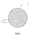
Fig. 3 is an enlarged cross-sectional view of an essential portion of the degassing element. -
Fig. 4 is a cross-sectional view showing an example of a connection method for the gas-permeable tubes in the gas removal device of the present invention. -
Fig. 5 is a configuration diagram of a degassing system using the gas removal device of the present invention. -
Fig. 6 is a half cross-sectional view of a gas removal device ofEmbodiment 2 of the present invention. -
Fig. 7 is a plan view of a degassing element shown inFig. 6 . -
Fig. 8 is a schematic view showing a deformation of the gas-permeable tubes when the tube bundle is bent. -
Fig. 9 is a cross-sectional view showing schematically an example of a conventional gas removal device. - Hereinbelow, embodiments of the present invention will be described with reference to the accompanying drawings.
-
Fig. 1 shows a gas removal device ofEmbodiment 1 of the present invention. Thegas removal device 1 includes adecompression chamber 2. Thedecompression chamber 2 includes aninlet 11 and anoutlet 12 through which a liquid to be degassed circulates, and avacuum suction port 13 to be connected to a decompression device. Thedecompression chamber 2 has acover 21, and a chambermain body 22 with a tubular shape. The chambermain body 22 has abottom portion 23 and anopening portion 24. Theinlet 11 and theoutlet 12 are provided at thecover 21. Thevacuum suction port 13 is provided at aside part 25 of the chambermain body 22. Thecover 21 is fixed to theopening portion 24 of the chambermain body 22 in such a manner that airtightness in thedecompression chamber 2 is maintained. Adegassing element 5 is disposed in thedecompression chamber 2. Thedegassing element 5 has an end connected to theinlet 11 and another end connected to theoutlet 12. - As shown in
Fig. 2 andFig. 3 , thedegassing element 5 has atube bundle 15 composed of a plurality of flexible gas-permeable tubes 151,tubular adapters tying members 16 tying the gas-permeable tubes 151. Theadapters inlet side adapter 141 attached to one end of thetube bundle 15 and connected to theinlet 11 of thedecompression chamber 2, and theoutlet side adapter 142 attached to another end of thetube bundle 15 and connected to theoutlet 12 of thedecompression chamber 2. The liquid to be degassed that has flowed into theinlet 11 via theinlet side adapter 141 circulates through thedegassing element 5, that is, circulates through the gas-permeable tubes 151, and then flows out from theoutlet 12 via theoutlet side adapter 142. - As shown in
Fig. 1 , thedegassing element 5 is accommodated in thedecompression chamber 2 while thetube bundle 15 is bent in a shape of coil with multiple turns. In other words, between theinlet side adapter 141 and theoutlet side adapter 142, a bent portion BP is formed by bending a part of thetube bundle 15 in a circular shape, and thetying members 16 each are disposed at plural points in the circular bent portion BP. When thus configured, a sufficient length of the tube bundle 15 (length of the gas-permeable tube 151) can be ensured while thedecompression chamber 2 of a small size is employed. Thus, the degassing capability of thegas removal device 1 can be enhanced relatively easily. - The
tying members 16 winding around thetube bundle 15 play a role of tying the gas-permeable tubes 151 into one bundle and maintaining the form of thetube bundle 15, as well as a role of preventing each of the gas-permeable tubes 151 from buckling when thetube bundle 15 is bent. When thetube bundle 15 is bent in a shape of coil with multiple turns to form the bent portion BP as shown inFig. 1 , bending stress is generated in the gas-permeable tubes 151. At this time, the form of the gas-permeable tubes 151 tends to change into one that can alleviate the stress. However, since thetube bundle 15 is bent in such a manner that portions tied by thetying members 16 are included in the bent portion BP, the form of the gas-permeable tubes 151 is not changed easily. As a result, the occurrence of buckling is prevented. Disposing the tyingmembers 16 on the bent portion BP at a predetermined interval allows the tying force to act evenly on the gas-permeable tubes 151 in a longitudinal direction. Thus, an enhanced effect of preventing buckling can be expected. - The gas-
permeable tubes inlet side adapter 141 and theoutlet side adapter 142. More specifically, the gas-permeable tubes adapters members 16 exert on the gas-permeable tubes 151 is not so large, the gas-permeable tubes 151 can move back and forth in the longitudinal direction. The tying members16 do not cover the gas-permeable tubes 151 entirely, and they are disposed along the longitudinal direction at a constant interval. That is, when thetube bundle 15 is bent, some of the gas-permeable tubes 151 located on an inner circumferential side move back and forth slightly in the longitudinal direction, and deform in such a manner that a portion of the gas-permeable tubes 151 not tied by the tyingmembers 16 is somewhat raised toward a center of the circle. As a result, the bending stress can be relaxed, enhancing the effect of preventing buckling. - Also, tying the gas-
permeable tubes 151 into one bundle improves the workability at the time of placing thedegassing element 5 in thedecompression chamber 2. Use of the tyingmembers 16 easily prevents the gas-permeable tubes 151 from being loose. This makes it unnecessary to bond the gas-permeable tubes permeable tubes degassing element 5 is expected to be enhanced. - As the tying
member 16, a string, a tube, a chain, and a film can be used, for example. Particularly, a thin film is preferable. When the tyingmember 16 is a film, it winds around thetube bundle 15, and thereby it can tie the plurality of gas-permeable tubes 151 in such a manner that it wraps them. Then, the tying force exerted by the tyingmember 16 acts on the gas-permeable tubes 151 in plane, and thereby an excellent effect of preventing buckling can be obtained. - The film used as the tying
member 16 preferably has gas permeability. Using the gas-permeable film as the tyingmember 16 makes it possible to tie the gas-permeable tubes 151 almost without deteriorating the gas permeability of the gas-permeable tubes 151. Specific examples of the gas-permeable film include a porous film, and a laminated film obtained by stacking a reinforcement material on the porous film. When the laminated film obtained by stacking a reinforcement material on a porous film is employed as the tyingmember 16, the reinforcing material preferably has gas permeability greater than that of the porous film. Specifically, a woven fabric, a nonwoven fabric, a mesh, a net, a sponge, a foam, a foamed material, and a porous material, these made of resin or metal, can be used as the reinforcement material. - Examples of the porous film suitable for the tying
member 16 include a porous film made of fluororesin, such as polytetrafluoroethylene (PTFE), tetrafluoroethylene-perfluoroalkyl vinyl ether copolymer, ethylene-tetrafluoroethylene copolymer, and polychlorotrifluoroethylene, as well as a porous film made of polyolefin, such as polyethylene and polypropylene. Among them, the porous film made of polytetrafluoroethylene is preferable because it has excellent gas permeability and chemical resistance. - The tying
member 16 may be of a strip-like shape. As shown in the cross-sectional view ofFig. 3 , both ends of the tyingmember 16 tying the gas-permeable tubes 151 are fixed to each other by an adhesive or thermal welding. Or the tyingmember 16 partially may be fixed to thetube bundle 15 using an adhesive etc. to prevent positional deviation of the tyingmember 16. In the present embodiment, the gas-permeable tubes 151 are tied by the tyingmembers 16 at a plurality of points along the longitudinal direction. When thus configured, the gas-permeable tubes 151 can be tied more reliably. Moreover, appropriately adjusting the interval at which the tyingmembers 16 are disposed can prevent the gas permeability of the gas-permeable tubes 151 from being deteriorated. - Other components will be described. Both of the
cover 21 and the chambermain body 22 of thedecompression chamber 2 are obtained by molding metal, glass, or plastic into a specific shape. As the metal, stainless steel is preferable because of its excellent chemical resistance. As the plastic, fluororesin and polyolefin can be used. Considering durability and the necessity for forming thevacuum suction port 13, thedecompression chamber 2 desirably is made of metal. - A tube commonly used in gas removal devices may be used as the gas-
permeable tubes 151. Specifically, there can be used a tube made of fluororesin, such as polytetrafluoroethylene (PTFE), tetrafluoroethylene-perfluoroalkyl vinyl ether copolymer, ethylene-tetrafluoroethylene copolymer, and polychlorotrifluoroethylene, or a tube made of polyolefin, such as polyethylene and polypropylene. In order to increase a membrane area per unit volume, thin hollow fibers preferably are used as the gas-permeable tubes 151 as shown inFig. 3 . In this case, an inner diameter of one hollow fiber (the gas-permeable tube 151) is in a range of about several tens of micrometers to several millimeters, and about several to several hundreds of hollow fibers generally constitute thesingle tube bundle 15. - In the present embodiment, the
tube bundle 15 is connected to theoutlet 11 and theinlet 12 via theadapters Fig. 4 can be employed as theadapters Fig. 4 , theadapters wedge 52, acap nut 51, and a mouth piece fitting 55 so as to be fixed to the end of thetube bundle 15. The mouth piece fitting 55 to which thetube bundle 15 is fixed is fixed to theinlet 11 or theoutlet 12 provided at thecover 21 by using anO ring 53 and anut 54. The mouth piece fitting 55 may be welded to thetube bundle 15 by using a thermally weldable fluororesin powder. Moreover, in the present embodiment, theinlet 11 and theoutlet 12 are provided at thecover 21, but theinlet 11 and/or theoutlet 12 can be provided at theside part 25 or thebottom portion 23 of the chambermain body 22 as well. - Next,
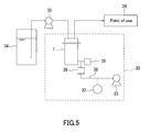
Fig. 5 shows a configuration diagram of a degassing system using the gas removal device ofFig. 1 . Adegassing system 30 is disposed between atank 34 holding the fluid that has not yet degassed and a point ofuse 36 of the fluid that has been degassed. Thedegassing system 30 includes: thegas removal device 1; a vacuum pump 33 (a decompression device) for decompressing inside of thedecompression chamber 2 of thegas removal device 1 to a pressure lower than an atmospheric pressure; avacuum suction pipe 38 that connects thevacuum pump 33 to thegas removal device 1 to form a vacuum line; avacuum gauge 32 for measuring a pressure in thevacuum suction pipe 38; and aliquid leakage sensor 31 located at a position closer to thegas removal device 1 than a position of thevacuum gauge 32 in the vacuum line. Thegas removal device 1 is installed in such a manner that thebottom portion 23 of the chambermain body 22 is oriented vertically downward, and thecover 21 with theinlet 11 and theoutlet 12 is oriented vertically upward. Apump 35 pumps up the fluid held in thetank 34 and sends it to thedegassing system 30, and then sends the degassed fluid to the point ofuse 36. - In the
degassing system 30 shown inFig. 5 , thevacuum gauge 32 disposed on the vacuum line between thegas removal device 1 and thevacuum pump 33 is checked for fluctuation. Thereby, the occurrence of liquid leakage can be judged. However, when the liquid leakage is small in amount, it is difficult to make the judgment promptly only from the fluctuation of thevacuum gauge 32. Therefore, it is preferable that the occurrence of the liquid leakage is judged based on a result of the detection by theliquid leakage sensor 31 so as to determine whether the degassing process should be stopped or continued. The type of theliquid leakage sensor 31 is not particularly limited. For example, a liquid leakage sensor having two conducting wires to detect a change in resistance between the conducting wires, or a liquid leakage sensor of optical fiber type can be used. Moreover, a detector, such as a liquid leakage sensor and a vacuum gauge, may be disposed in thedecompression chamber 2 of thegas removal device 1. - As shown in
Fig. 5 , in thedegassing system 30, aliquid trap 39 may be disposed on the vacuum line between thegas removal device 1 and thevacuum pump 33. Theliquid trap 39 plays a role of preventing the liquid to be degassed that has flowed into thevacuum suction pipe 38 via thevacuum suction port 13 from being drawn into thevacuum pump 33 and contacting thevacuum gauge 32. When thus configured, thevacuum gauge 32 and thevacuum pump 33 can be protected from failure. - As the
liquid trap 39, it is possible to use a small chamber capable of holding a liquid, and a component including a gas permeable filter that allows a gas to permeate therethrough while preventing a liquid from permeating therethrough. A specific example of such a gas permeable filter is a porous filter including a porous membrane made of fluororesin or polyolefin resin. Specifically, theliquid trap 39 is disposed between theliquid leakage sensor 31 and thevacuum pump 33 on the vacuum line, preferably between theliquid leakage sensor 31 and thevacuum gauge 32. -
Fig. 6 shows a gas removal device ofEmbodiment 2 of the present invention. A difference between the gas removal device ofEmbodiment 1 described previously and the gas removal device ofEmbodiment 2 is the way of tying the gas-permeable tubes constituting the degassing element. Other configurations are common between the embodiments, as understood from the fact that they use the same reference numerals. - As shown in
Fig. 6 , thegas removal device 10 of the present embodiment includes thedecompression chamber 2, and adegassing element 50 disposed in thedecompression chamber 2. The configuration of thedecompression chamber 2 is as described inEmbodiment 1. As shown inFig. 7 , thedegassing element 50 is composed of thetube bundle 15 including the plurality of gas-permeable tubes 151, a tyingmember 17 tying the gas-permeable tubes 151, and theadapters - The
degassing element 50 is accommodated in thedecompression chamber 2 while thetube bundle 15 is bent in a shape of coil with multiple turns. In other words, the bent portion BP is formed by bending in a circular shape a part of thetube bundle 15 wound by the tyingmember 17 between theinlet side adapter 141 and theoutlet side adapter 142. When thus configured, a sufficient length of the tube bundle 15 (length of the gas-permeable tube 151) can be ensured while thedecompression chamber 2 of a small size is employed. Thus, the degassing capability of thegas removal device 10 can be enhanced relatively easily. - The tying
member 17 winding spirally around thetube bundle 15 plays a role of tying the gas-permeable tubes 151 into one bundle, as well as a role of preventing each of the gas-permeable tubes 151 from buckling when thetube bundle 15 is bent. When thetube bundle 15 is bent in a shape of coil with multiple turns and the bent portion BP is formed as shown inFig. 6 , bending stress is generated in the gas-permeable tubes 151. At this time, the form of the gas-permeable tubes 151 tends to be changed into one that can alleviate the stress. However, since thetube bundle 15 is bent in such a manner that a portion tied by the tyingmember 17 is included in the bent portion BP, the form of the gas-permeable tubes 151 does not change easily. As a result, occurrence of the buckling is prevented. - The gas-
permeable tubes inlet side adapter 141 and theoutlet side adapter 142. More specifically, the gas-permeable tubes adapters member 17 exerts on the gas-permeable tubes 151 is not so large. Accordingly, when thetube bundle 15 is bent, some of the gas-permeable tubes 151 located on the inner circumferential side move back and forth slightly in the longitudinal direction, relaxing the bending stress. Such a stress relaxation effect obtained by warpage of the gas-permeable tubes 151 is as described inEmbodiment 1. However, the present embodiment is more effective thanEmbodiment 1 in preventing the gas-permeable tubes 151 from buckling. The reason is as follows. - As shown in
Fig. 8 , when thedegassing element 5 described inEmbodiment 1 is bent, some of the gas-permeable tubes 151 located on the inner circumferential side are warped between two of the tyingmembers 16 adjacent to each other, and awarped portion 27k is formed in some cases. Thewarped portion 27k is not a serious problem as long as it does not hinder the circulation of the liquid. However, it possibly could result in buckling of the gas-permeable tubes 151. Thus, thewarped portion 27k should not be formed. In order to prevent the formation of thewarped portion 27k, a tying force acts evenly on the entire gas-permeable tubes 151 in the longitudinal direction. Disposing the tyingmembers 16 at a short interval makes it easy for the tying force to act evenly on the entire gas-permeable tubes 151 in the longitudinal direction. It should be noted, however, that when the interval at which the tyingmembers 16 are disposed is too short, the gas permeability of the gas-permeable tubes 151 possibly may be deteriorated. - In contrast, the long tying
member 17 winds spirally around thetube bundle 15 in the present embodiment. Thus, the tying force that the tyingmember 17 exerts on the gas-permeable tubes 151 is more even in the longitudinal direction of the gas-permeable tubes 151 than that inEmbodiment 1. Accordingly, thewarped portion 27k as shown inFig. 8 hardly is formed, and a greater effect of preventing buckling can be obtained. - Preferable materials for the tying
member 17 are as described inEmbodiment 1. - It is preferable that the tying
member 17 is of a strip-like shape, and that both ends thereof are fixed to thetube bundle 15 or theadapters member 17 appropriately makes it possible to prevent the tyingmember 17 from deteriorating the gas permeability of the gas-permeable tubes 151. The single strip-like tyingmember 17 winds spirally around thetube bundle 15 in the present embodiment. It is also possible that the same single tyingmember 17 is prepared additionally, and the two tyingmembers tube bundle 15 to form a double spiral. Such a configuration allows the gas-permeable tubes 151 to be tied more reliably, and allows the tying force to act more evenly. As a result, an excellent effect of preventing buckling can be obtained.
Claims (13)
- A gas removal device comprising:a decompression chamber with an inlet and an outlet through which a liquid to be degassed flows therein and thereout; anda degassing element that is accommodated in the decompression chamber while having one end connected to the inlet and another end connected to the outlet, and that allows the liquid to be degassed entering into the inlet to passes through the degassing element, wherein:the degassing element includes a tube bundle composed of a plurality of flexible gas-permeable tubes, and a tying member tying the plurality of gas-permeable tubes to form the tube bundle;the degassing element is accommodated in the decompression chamber in such a manner that at least a part of the tube bundle makes a bent portion formed by bending the tube bundle; andthe tying member is disposed on at least a part of the bent portion.
- The gas removal device according to claim 1, wherein the tying member is a film, and the film winds around the tube bundle to tie the plurality of gas-permeable tubes into one bundle.
- The gas removal device according to claim 2, wherein the film has gas permeability.
- The gas removal device according to claim 3, wherein the film includes a porous film.
- The gas removal device according to claim 4, wherein the porous film is made of polytetrafluoroethylene.
- The gas removal device according to claim 1, wherein the degassing element is provided with a plurality of the tying members tying the gas-permeable tubes at a plurality of points along a longitudinal direction of the tubes.
- The gas removal device according to claim 1, wherein:the degassing element further includes an inlet side adapter attached to one end of the tube bundle and connected to the inlet, and an outlet side adapter attached to another end of the tube bundle and connected to the outlet;the bent portion is formed by bending the tube bundle in a circular shape between the inlet side adapter and the outlet side adapter; andthe tying members are disposed on the circular bent portion at a predetermined interval.
- A gas removal device comprising:a decompression chamber with an inlet and an outlet through which a liquid to be degassed flows therein and thereout; anda degassing element that is accommodated in the decompression chamber while having one end connected to the inlet and another end connected to the outlet, and that allows the liquid to be degassed entering into the inlet to pass through the degassing element, wherein:the degassing element includes a tube bundle composed of a plurality of gas-permeable tubes, and a tying member winding spirally around the tube bundle to tie the gas-permeable tubes; andat least a part of the tube bundle wound by the tying member is bent.
- The gas removal device according to claim 8, wherein the tying member is a film.
- The gas removal device according to claim 9, wherein the film has gas permeability.
- The gas removal device according to claim 10, wherein the film includes a porous film.
- The gas removal device according to claim 11, wherein the porous film is made of polytetrafluoroethylene.
- The gas removal device according to claim 8, wherein:the degassing element further includes an inlet side adapter attached to one end of the tube bundle and connected to the inlet, and an outlet side adapter attached to another end of the tube bundle and connected to the outlet; anda bent portion is formed by bending in a circular shape the part of the tube bundle wound by the tying member between the inlet side adapter and the outlet side adapter.
Applications Claiming Priority (3)
| Application Number | Priority Date | Filing Date | Title |
|---|---|---|---|
| JP2006257494A JP4969965B2 (en) | 2006-09-22 | 2006-09-22 | Deaerator |
| JP2006257495A JP4969966B2 (en) | 2006-09-22 | 2006-09-22 | Deaerator |
| PCT/JP2007/068202 WO2008035714A1 (en) | 2006-09-22 | 2007-09-19 | Gas removal device |
Publications (3)
| Publication Number | Publication Date |
|---|---|
| EP2070573A1 true EP2070573A1 (en) | 2009-06-17 |
| EP2070573A4 EP2070573A4 (en) | 2011-06-15 |
| EP2070573B1 EP2070573B1 (en) | 2012-05-16 |
Family
ID=39200539
Family Applications (1)
| Application Number | Title | Priority Date | Filing Date |
|---|---|---|---|
| EP07807571A Not-in-force EP2070573B1 (en) | 2006-09-22 | 2007-09-19 | Gas removal device |
Country Status (5)
| Country | Link |
|---|---|
| US (1) | US8177889B2 (en) |
| EP (1) | EP2070573B1 (en) |
| KR (1) | KR101128592B1 (en) |
| TW (1) | TWI391174B (en) |
| WO (1) | WO2008035714A1 (en) |
Families Citing this family (16)
| Publication number | Priority date | Publication date | Assignee | Title |
|---|---|---|---|---|
| DE102009016694A1 (en) * | 2009-04-07 | 2010-10-14 | Linde Aktiengesellschaft | Membrane tube and reactor with membrane tube |
| US8430949B2 (en) * | 2011-03-25 | 2013-04-30 | Idex Health & Science Llc | Apparatus for pervaporation control in liquid degassing systems |
| DE102012222020B4 (en) * | 2012-11-30 | 2022-03-31 | Airbus Operations Gmbh | System for supplying inert gas to an aircraft, method for supplying inert gas to an aircraft, use of a membrane and aircraft |
| US9370734B2 (en) * | 2013-06-26 | 2016-06-21 | Idex Health & Science, Llc | Fluid degassing module with helical membrane |
| JP2015016400A (en) * | 2013-07-09 | 2015-01-29 | 三菱レイヨン株式会社 | Hollow fiber membrane and hollow fiber membrane module for deaeration |
| US20150380278A1 (en) * | 2014-06-30 | 2015-12-31 | Lam Research Corporation | Hardware for the separation and degassing of dissolved gases in semiconductor precursor chemicals |
| WO2016016946A1 (en) * | 2014-07-29 | 2016-02-04 | 株式会社島津製作所 | Degassing device |
| DE102016220107B4 (en) * | 2016-10-14 | 2020-01-02 | Fraunhofer-Gesellschaft zur Förderung der angewandten Forschung e.V. | degassing |
| KR20210139430A (en) | 2019-03-26 | 2021-11-22 | 버슘머트리얼즈 유에스, 엘엘씨 | Degassing apparatus, degassing system and method of using same |
| JP7420249B2 (en) * | 2020-06-08 | 2024-01-23 | Dic株式会社 | Tube unit, degassing module, and tube unit manufacturing method |
| JP7400869B2 (en) * | 2022-05-13 | 2023-12-19 | Dic株式会社 | chemical analyzer |
| JPWO2024004829A1 (en) * | 2022-06-27 | 2024-01-04 | ||
| JP7715284B2 (en) * | 2022-06-27 | 2025-07-30 | Dic株式会社 | Degassing device |
| US20250387733A1 (en) * | 2022-06-27 | 2025-12-25 | Dic Corporation | Deaerator |
| KR102673894B1 (en) * | 2023-08-31 | 2024-06-07 | 홍광호 | Degassing device and the manufacturing method thereof |
| KR102901001B1 (en) * | 2025-07-04 | 2025-12-19 | 포이스 주식회사 | Degassing apparatus for chemicals |
Family Cites Families (17)
| Publication number | Priority date | Publication date | Assignee | Title |
|---|---|---|---|---|
| JPS6421712U (en) * | 1987-07-24 | 1989-02-03 | ||
| US5183486A (en) * | 1990-12-04 | 1993-02-02 | Spectra-Physics, Inc. | Apparatus for degassing a liquid |
| WO1993012866A1 (en) * | 1991-12-20 | 1993-07-08 | The Dow Chemical Company | Flexible hollow fiber fluid separation module |
| US5202023A (en) * | 1991-12-20 | 1993-04-13 | The Dow Chemical Company | Flexible hollow fiber fluid separation module |
| EP0598424A3 (en) * | 1992-11-16 | 1996-05-15 | Novellus Systems Inc | Apparatus for removing dissolved gases from a liquid. |
| US5340384A (en) * | 1993-03-05 | 1994-08-23 | Systec, Inc. | Vacuum degassing |
| JPH07112529B2 (en) * | 1993-08-20 | 1995-12-06 | 株式会社ニッショー | How to wrap a fiber bundle |
| US5858199A (en) * | 1995-07-17 | 1999-01-12 | Apogee Corporation | Apparatus and method for electrocoriolysis the separation of ionic substances from liquids by electromigration and coriolis force |
| JPH10165708A (en) | 1996-12-09 | 1998-06-23 | Nitto Denko Corp | Degassing device |
| JP4008576B2 (en) | 1998-05-26 | 2007-11-14 | 日東電工株式会社 | Deaerator |
| US6346187B1 (en) * | 1999-01-21 | 2002-02-12 | The Regents Of The University Of California | Alternating-polarity operation for complete regeneration of electrochemical deionization system |
| US6248157B1 (en) * | 1999-08-20 | 2001-06-19 | Systec Inc. | Vacuum degassing |
| US6837992B2 (en) * | 2001-07-10 | 2005-01-04 | Systec Inc. | Integrated apparatus for degassing and blending multiple mobile phase streams |
| JP4341947B2 (en) * | 2002-06-14 | 2009-10-14 | 株式会社潤工社 | Separation membrane module |
| JP4289603B2 (en) * | 2003-04-28 | 2009-07-01 | 日東電工株式会社 | Spiral type membrane element and manufacturing method thereof |
| US7332065B2 (en) * | 2003-06-19 | 2008-02-19 | Akzo Nobel N.V. | Electrode |
| TWI388368B (en) * | 2006-05-01 | 2013-03-11 | Nitto Denko Corp | Degassing apparatus |
-
2007
- 2007-09-19 WO PCT/JP2007/068202 patent/WO2008035714A1/en not_active Ceased
- 2007-09-19 US US12/441,616 patent/US8177889B2/en not_active Expired - Fee Related
- 2007-09-19 EP EP07807571A patent/EP2070573B1/en not_active Not-in-force
- 2007-09-19 KR KR1020097008090A patent/KR101128592B1/en not_active Expired - Fee Related
- 2007-09-21 TW TW096135317A patent/TWI391174B/en not_active IP Right Cessation
Also Published As
| Publication number | Publication date |
|---|---|
| US8177889B2 (en) | 2012-05-15 |
| TW200817077A (en) | 2008-04-16 |
| TWI391174B (en) | 2013-04-01 |
| EP2070573A4 (en) | 2011-06-15 |
| WO2008035714A1 (en) | 2008-03-27 |
| US20090301306A1 (en) | 2009-12-10 |
| EP2070573B1 (en) | 2012-05-16 |
| KR101128592B1 (en) | 2012-03-23 |
| KR20090057452A (en) | 2009-06-05 |
Similar Documents
| Publication | Publication Date | Title |
|---|---|---|
| US8177889B2 (en) | Gas removal device | |
| US7264725B2 (en) | Hollow fiber membrane contactor and method of making same | |
| JP6283973B2 (en) | Method for producing hollow fiber membrane module | |
| CN104772041B (en) | Hollow fiber film assembly and filter method | |
| WO2002049746A1 (en) | Hollow fiber membrane module, method of manufacturing the hollow fiber membrane module, and housing for hollow fiber membrane module | |
| CN101516463B (en) | Gas removal device | |
| CN104703674A (en) | Gas-separating membrane module | |
| US12194416B2 (en) | Membrane distillation module and membrane distillation apparatus | |
| JP2005195178A (en) | Liquid-gas type hydraulic accumulator | |
| CN111514759A (en) | Hollow fiber membrane module and method for manufacturing hollow fiber membrane module | |
| US20100224548A1 (en) | Screen-Like Object Made of Hollow Fibers, a Method of Manufacturing a Hollow Fiber Bundle, a Cylindrical Module of Hollow Fiber Membrane, and an Immersion Type Module of Hollow Fiber Membrane | |
| JP5015189B2 (en) | Hollow fiber membrane module and filtration method using the same | |
| CN110314549B (en) | Rolling type membrane element, rolling type membrane filter element and rolling type membrane column | |
| JP2011104508A (en) | Degassing system | |
| JP4969966B2 (en) | Deaerator | |
| EP1946823A1 (en) | Hollow fiber bundle, process for producing hollow fiber bundle, tubular hollow fiber membrane module and immersion type hollow fiber membrane module | |
| JP2006297200A (en) | Deaerator | |
| JP7548457B1 (en) | Flat Membrane Module | |
| JPH0938410A (en) | Porous membrane element | |
| EP4494750A1 (en) | Spiral membrane element, transmission spacer, and membrane separation method | |
| JPH04247223A (en) | Hollow-fiber membrane module | |
| CN118524886A (en) | Spiral membrane element | |
| JP2007152182A (en) | Deaeration device and deaeration system |
Legal Events
| Date | Code | Title | Description |
|---|---|---|---|
| PUAI | Public reference made under article 153(3) epc to a published international application that has entered the european phase |
Free format text: ORIGINAL CODE: 0009012 |
|
| 17P | Request for examination filed |
Effective date: 20090416 |
|
| AK | Designated contracting states |
Kind code of ref document: A1 Designated state(s): AT BE BG CH CY CZ DE DK EE ES FI FR GB GR HU IE IS IT LI LT LU LV MC MT NL PL PT RO SE SI SK TR |
|
| A4 | Supplementary search report drawn up and despatched |
Effective date: 20110512 |
|
| GRAP | Despatch of communication of intention to grant a patent |
Free format text: ORIGINAL CODE: EPIDOSNIGR1 |
|
| RIC1 | Information provided on ipc code assigned before grant |
Ipc: B01D 71/36 20060101ALI20111219BHEP Ipc: B01D 63/02 20060101ALI20111219BHEP Ipc: B01D 19/00 20060101AFI20111219BHEP |
|
| DAX | Request for extension of the european patent (deleted) | ||
| GRAS | Grant fee paid |
Free format text: ORIGINAL CODE: EPIDOSNIGR3 |
|
| GRAA | (expected) grant |
Free format text: ORIGINAL CODE: 0009210 |
|
| AK | Designated contracting states |
Kind code of ref document: B1 Designated state(s): AT BE BG CH CY CZ DE DK EE ES FI FR GB GR HU IE IS IT LI LT LU LV MC MT NL PL PT RO SE SI SK TR |
|
| REG | Reference to a national code |
Ref country code: GB Ref legal event code: FG4D |
|
| REG | Reference to a national code |
Ref country code: CH Ref legal event code: EP |
|
| REG | Reference to a national code |
Ref country code: AT Ref legal event code: REF Ref document number: 557758 Country of ref document: AT Kind code of ref document: T Effective date: 20120615 |
|
| REG | Reference to a national code |
Ref country code: IE Ref legal event code: FG4D |
|
| REG | Reference to a national code |
Ref country code: DE Ref legal event code: R096 Ref document number: 602007022732 Country of ref document: DE Effective date: 20120712 |
|
| REG | Reference to a national code |
Ref country code: NL Ref legal event code: VDEP Effective date: 20120516 |
|
| REG | Reference to a national code |
Ref country code: LT Ref legal event code: MG4D Effective date: 20120516 |
|
| PG25 | Lapsed in a contracting state [announced via postgrant information from national office to epo] |
Ref country code: SE Free format text: LAPSE BECAUSE OF FAILURE TO SUBMIT A TRANSLATION OF THE DESCRIPTION OR TO PAY THE FEE WITHIN THE PRESCRIBED TIME-LIMIT Effective date: 20120516 Ref country code: PL Free format text: LAPSE BECAUSE OF FAILURE TO SUBMIT A TRANSLATION OF THE DESCRIPTION OR TO PAY THE FEE WITHIN THE PRESCRIBED TIME-LIMIT Effective date: 20120516 Ref country code: IS Free format text: LAPSE BECAUSE OF FAILURE TO SUBMIT A TRANSLATION OF THE DESCRIPTION OR TO PAY THE FEE WITHIN THE PRESCRIBED TIME-LIMIT Effective date: 20120916 Ref country code: LT Free format text: LAPSE BECAUSE OF FAILURE TO SUBMIT A TRANSLATION OF THE DESCRIPTION OR TO PAY THE FEE WITHIN THE PRESCRIBED TIME-LIMIT Effective date: 20120516 Ref country code: CY Free format text: LAPSE BECAUSE OF FAILURE TO SUBMIT A TRANSLATION OF THE DESCRIPTION OR TO PAY THE FEE WITHIN THE PRESCRIBED TIME-LIMIT Effective date: 20120516 Ref country code: FI Free format text: LAPSE BECAUSE OF FAILURE TO SUBMIT A TRANSLATION OF THE DESCRIPTION OR TO PAY THE FEE WITHIN THE PRESCRIBED TIME-LIMIT Effective date: 20120516 |
|
| REG | Reference to a national code |
Ref country code: AT Ref legal event code: MK05 Ref document number: 557758 Country of ref document: AT Kind code of ref document: T Effective date: 20120516 |
|
| PG25 | Lapsed in a contracting state [announced via postgrant information from national office to epo] |
Ref country code: LV Free format text: LAPSE BECAUSE OF FAILURE TO SUBMIT A TRANSLATION OF THE DESCRIPTION OR TO PAY THE FEE WITHIN THE PRESCRIBED TIME-LIMIT Effective date: 20120516 Ref country code: SI Free format text: LAPSE BECAUSE OF FAILURE TO SUBMIT A TRANSLATION OF THE DESCRIPTION OR TO PAY THE FEE WITHIN THE PRESCRIBED TIME-LIMIT Effective date: 20120516 Ref country code: GR Free format text: LAPSE BECAUSE OF FAILURE TO SUBMIT A TRANSLATION OF THE DESCRIPTION OR TO PAY THE FEE WITHIN THE PRESCRIBED TIME-LIMIT Effective date: 20120817 Ref country code: PT Free format text: LAPSE BECAUSE OF FAILURE TO SUBMIT A TRANSLATION OF THE DESCRIPTION OR TO PAY THE FEE WITHIN THE PRESCRIBED TIME-LIMIT Effective date: 20120917 |
|
| PG25 | Lapsed in a contracting state [announced via postgrant information from national office to epo] |
Ref country code: BE Free format text: LAPSE BECAUSE OF FAILURE TO SUBMIT A TRANSLATION OF THE DESCRIPTION OR TO PAY THE FEE WITHIN THE PRESCRIBED TIME-LIMIT Effective date: 20120516 |
|
| PG25 | Lapsed in a contracting state [announced via postgrant information from national office to epo] |
Ref country code: EE Free format text: LAPSE BECAUSE OF FAILURE TO SUBMIT A TRANSLATION OF THE DESCRIPTION OR TO PAY THE FEE WITHIN THE PRESCRIBED TIME-LIMIT Effective date: 20120516 Ref country code: CZ Free format text: LAPSE BECAUSE OF FAILURE TO SUBMIT A TRANSLATION OF THE DESCRIPTION OR TO PAY THE FEE WITHIN THE PRESCRIBED TIME-LIMIT Effective date: 20120516 Ref country code: DK Free format text: LAPSE BECAUSE OF FAILURE TO SUBMIT A TRANSLATION OF THE DESCRIPTION OR TO PAY THE FEE WITHIN THE PRESCRIBED TIME-LIMIT Effective date: 20120516 Ref country code: AT Free format text: LAPSE BECAUSE OF FAILURE TO SUBMIT A TRANSLATION OF THE DESCRIPTION OR TO PAY THE FEE WITHIN THE PRESCRIBED TIME-LIMIT Effective date: 20120516 Ref country code: RO Free format text: LAPSE BECAUSE OF FAILURE TO SUBMIT A TRANSLATION OF THE DESCRIPTION OR TO PAY THE FEE WITHIN THE PRESCRIBED TIME-LIMIT Effective date: 20120516 Ref country code: NL Free format text: LAPSE BECAUSE OF FAILURE TO SUBMIT A TRANSLATION OF THE DESCRIPTION OR TO PAY THE FEE WITHIN THE PRESCRIBED TIME-LIMIT Effective date: 20120516 Ref country code: SK Free format text: LAPSE BECAUSE OF FAILURE TO SUBMIT A TRANSLATION OF THE DESCRIPTION OR TO PAY THE FEE WITHIN THE PRESCRIBED TIME-LIMIT Effective date: 20120516 |
|
| PG25 | Lapsed in a contracting state [announced via postgrant information from national office to epo] |
Ref country code: IT Free format text: LAPSE BECAUSE OF FAILURE TO SUBMIT A TRANSLATION OF THE DESCRIPTION OR TO PAY THE FEE WITHIN THE PRESCRIBED TIME-LIMIT Effective date: 20120516 |
|
| PLBE | No opposition filed within time limit |
Free format text: ORIGINAL CODE: 0009261 |
|
| STAA | Information on the status of an ep patent application or granted ep patent |
Free format text: STATUS: NO OPPOSITION FILED WITHIN TIME LIMIT |
|
| 26N | No opposition filed |
Effective date: 20130219 |
|
| PG25 | Lapsed in a contracting state [announced via postgrant information from national office to epo] |
Ref country code: MC Free format text: LAPSE BECAUSE OF NON-PAYMENT OF DUE FEES Effective date: 20120930 Ref country code: ES Free format text: LAPSE BECAUSE OF FAILURE TO SUBMIT A TRANSLATION OF THE DESCRIPTION OR TO PAY THE FEE WITHIN THE PRESCRIBED TIME-LIMIT Effective date: 20120827 |
|
| REG | Reference to a national code |
Ref country code: CH Ref legal event code: PL |
|
| REG | Reference to a national code |
Ref country code: DE Ref legal event code: R097 Ref document number: 602007022732 Country of ref document: DE Effective date: 20130219 |
|
| REG | Reference to a national code |
Ref country code: IE Ref legal event code: MM4A |
|
| PG25 | Lapsed in a contracting state [announced via postgrant information from national office to epo] |
Ref country code: CH Free format text: LAPSE BECAUSE OF NON-PAYMENT OF DUE FEES Effective date: 20120930 Ref country code: IE Free format text: LAPSE BECAUSE OF NON-PAYMENT OF DUE FEES Effective date: 20120919 Ref country code: BG Free format text: LAPSE BECAUSE OF FAILURE TO SUBMIT A TRANSLATION OF THE DESCRIPTION OR TO PAY THE FEE WITHIN THE PRESCRIBED TIME-LIMIT Effective date: 20120816 Ref country code: LI Free format text: LAPSE BECAUSE OF NON-PAYMENT OF DUE FEES Effective date: 20120930 |
|
| PGFP | Annual fee paid to national office [announced via postgrant information from national office to epo] |
Ref country code: DE Payment date: 20130911 Year of fee payment: 7 |
|
| PG25 | Lapsed in a contracting state [announced via postgrant information from national office to epo] |
Ref country code: MT Free format text: LAPSE BECAUSE OF FAILURE TO SUBMIT A TRANSLATION OF THE DESCRIPTION OR TO PAY THE FEE WITHIN THE PRESCRIBED TIME-LIMIT Effective date: 20120516 |
|
| PGFP | Annual fee paid to national office [announced via postgrant information from national office to epo] |
Ref country code: GB Payment date: 20130918 Year of fee payment: 7 Ref country code: FR Payment date: 20130910 Year of fee payment: 7 |
|
| PG25 | Lapsed in a contracting state [announced via postgrant information from national office to epo] |
Ref country code: TR Free format text: LAPSE BECAUSE OF FAILURE TO SUBMIT A TRANSLATION OF THE DESCRIPTION OR TO PAY THE FEE WITHIN THE PRESCRIBED TIME-LIMIT Effective date: 20120516 |
|
| PG25 | Lapsed in a contracting state [announced via postgrant information from national office to epo] |
Ref country code: LU Free format text: LAPSE BECAUSE OF NON-PAYMENT OF DUE FEES Effective date: 20120919 |
|
| PG25 | Lapsed in a contracting state [announced via postgrant information from national office to epo] |
Ref country code: HU Free format text: LAPSE BECAUSE OF FAILURE TO SUBMIT A TRANSLATION OF THE DESCRIPTION OR TO PAY THE FEE WITHIN THE PRESCRIBED TIME-LIMIT Effective date: 20070919 |
|
| REG | Reference to a national code |
Ref country code: DE Ref legal event code: R119 Ref document number: 602007022732 Country of ref document: DE |
|
| GBPC | Gb: european patent ceased through non-payment of renewal fee |
Effective date: 20140919 |
|
| REG | Reference to a national code |
Ref country code: DE Ref legal event code: R119 Ref document number: 602007022732 Country of ref document: DE Effective date: 20150401 |
|
| REG | Reference to a national code |
Ref country code: FR Ref legal event code: ST Effective date: 20150529 |
|
| PG25 | Lapsed in a contracting state [announced via postgrant information from national office to epo] |
Ref country code: GB Free format text: LAPSE BECAUSE OF NON-PAYMENT OF DUE FEES Effective date: 20140919 Ref country code: DE Free format text: LAPSE BECAUSE OF NON-PAYMENT OF DUE FEES Effective date: 20150401 |
|
| PG25 | Lapsed in a contracting state [announced via postgrant information from national office to epo] |
Ref country code: FR Free format text: LAPSE BECAUSE OF NON-PAYMENT OF DUE FEES Effective date: 20140930 |