EP2070153B1 - Telescopic mast having reduced play - Google Patents
Telescopic mast having reduced play Download PDFInfo
- Publication number
- EP2070153B1 EP2070153B1 EP07801369.5A EP07801369A EP2070153B1 EP 2070153 B1 EP2070153 B1 EP 2070153B1 EP 07801369 A EP07801369 A EP 07801369A EP 2070153 B1 EP2070153 B1 EP 2070153B1
- Authority
- EP
- European Patent Office
- Prior art keywords
- telescoping sections
- walls
- telescoping
- adjacent
- telescopic mast
- Prior art date
- Legal status (The legal status is an assumption and is not a legal conclusion. Google has not performed a legal analysis and makes no representation as to the accuracy of the status listed.)
- Not-in-force
Links
- 239000000463 material Substances 0.000 description 6
- 239000004809 Teflon Substances 0.000 description 4
- 229920006362 Teflon® Polymers 0.000 description 4
- 238000010276 construction Methods 0.000 description 1
- 238000006073 displacement reaction Methods 0.000 description 1
- 239000007788 liquid Substances 0.000 description 1
Images


Classifications
-
- H—ELECTRICITY
- H01—ELECTRIC ELEMENTS
- H01Q—ANTENNAS, i.e. RADIO AERIALS
- H01Q1/00—Details of, or arrangements associated with, antennas
- H01Q1/12—Supports; Mounting means
- H01Q1/1235—Collapsible supports; Means for erecting a rigid antenna
-
- F—MECHANICAL ENGINEERING; LIGHTING; HEATING; WEAPONS; BLASTING
- F16—ENGINEERING ELEMENTS AND UNITS; GENERAL MEASURES FOR PRODUCING AND MAINTAINING EFFECTIVE FUNCTIONING OF MACHINES OR INSTALLATIONS; THERMAL INSULATION IN GENERAL
- F16B—DEVICES FOR FASTENING OR SECURING CONSTRUCTIONAL ELEMENTS OR MACHINE PARTS TOGETHER, e.g. NAILS, BOLTS, CIRCLIPS, CLAMPS, CLIPS OR WEDGES; JOINTS OR JOINTING
- F16B7/00—Connections of rods or tubes, e.g. of non-circular section, mutually, including resilient connections
- F16B7/10—Telescoping systems
- F16B7/14—Telescoping systems locking in intermediate non-discrete positions
Definitions
- the present invention concerns a telescopic mast including two or more cylindric telescoping sections with parallel walls, where the distal one of two adjacent telescoping sections is narrower than the proximal one of the two adjacent telescoping sections, so that the distal telescoping section can be moved into and out of the proximal telescoping section, respectively, wherein in the interspace between two adjacent telescoping sections there is provided at least one means interacting with an actuator and pressing the adjacent walls away from each other.
- telescopic masts There are many kinds of telescopic masts of which some can be extended automatically. In connection with telescoping masts, e.g. for military use, there are special requirements to stability and accuracy.
- US 4,151,534 describe a free-standing mast for an antenna including a number of telescoping tubes.
- US 4,137,535 describe a telescopic mast which is controlled pneumatically. The mast includes a number of telescoping tubes that may be collapsed in a base section. A piston is integrated in each section.
- WO 0189981 describes a telescoping member with a nut which is rotatably fastened to a frame, a rotary pipe with thread engaging the nut.
- a telescopic mast as mentioned in the introductory paragraph is know from EP 0 730 098 A1 which discloses two collars having cam surfaces and which are rotated around their common axis in relation to each other in order to establish a clamping force and from US 6,152,638 A in which two wedge shaped members are interacting when they are mutually displaced in order to establish a clamping force.
- Telescopic masts can be very high and may be used for sensors and weapons as well as for pointing out targets.
- High telescopic masts contain many telescoping sections. As play occurs between all adjacent telescoping sections of the mast, the play will accumulate in connection with high masts. Therefore, not the least in connection with high telescopic masts, it will very appropriate to minimise the play occurring between adjacent telescoping sections.
- the object of the present invention is to provide a telescopic mast where the play between the telescoping sections is minimised. It is a further object of the invention to provide a telescopic mast that may be positioned with great accuracy.
- a telescopic mast including two or more cylindric telescoping sections with parallel walls, where the distal one of two adjacent telescoping sections is narrower than the proximal one of the two adjacent telescoping sections, so that the distal telescoping section can be moved into and out of the proximal telescoping section, respectively, wherein in the interspace between two adjacent telescoping sections there is provided at least one means that interacts with an actuator and presses the adjacent walls away from each other where the telescopic mast is peculiar in that the means is a rotary means interacting with an actuator which during use rotates the rotary means about an axis which is largely perpendicular to the longitudinal axis of the telescoping sections.
- a telescopic mast according to the invention is thus achieved a number of advantages, as the means pressing the adjacent walls away from each other minimises the play occurring between adjacent telescoping sections. By pressing the adjacent walls away from each other, the play is eliminated or minimised.
- the telescopic mast is advantageous as it enables using a rotary means which is elongated and has large contact surface, thereby enabling the provision of a continuous action on the walls in direction away from each other. It may be advantageous to use a rotary means which is slightly asymmetrical and/or in which the axis of rotation is displaced in relation to the central part of the means. Hereby is provided the possibility of positional variation of the areas on the means which are in contact with the walls.
- the rotary means may advantageously be covered by a friction reducing material, e.g. Teflon, in order to minimise friction and wear.
- the telescopic mast according to the invention is peculiar in that there is used at least three rotary means and/or rotary members and/or displacing means. It will be suitable to distribute them with approximately the same mutual spacing so that adjacent telescoping sections are secured in a concentric position. Three rotary means and/or rotary members and/or displacing means are the lowest number that can ensure the securing of the adjacent telescoping sections in concentric position.
- the telescopic mast according to the invention is peculiar in that a pipe is provided within the telescoping sections.
- a pipe is provided within the telescoping sections.
- Power cables will often be required to power central parts, such as actuators, or other equipment disposed along the telescoping sections or at the top of the mast.
- Means of different nature with regard to design as well as material may be used. It may be advantageous to make the means of materials that are dimensionally stable in connection with large temperature fluctuations. It may furthermore be advantageous to coat the means with a layer of friction reducing material, as e.g. Teflon, for minimising friction between and wear of the elements involved.
- a layer of friction reducing material as e.g. Teflon
- the used actuators may e.g. be electric or pneumatic.
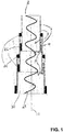
- Fig. 1 shows a general construction of a mast 2 according to the invention.
- the mast 2 includes three cylindric telescoping sections 4 with walls 6.
- An outer guide 26 is provided at the outer sides of the walls, near the proximal end of each telescoping section 4.
- an inner 24 is provided at the inner side of the walls 6 near the distal end of the walls.
- a means 10 interacting with an actuator 16 is provided in the interspace 8 between two adjacent telescoping sections 6.
- the actuator 16 is connected to a pipe 28 running through the inner cavity 3 of the telescoping sections. Electric power cables (not shown) run inside the pipe 28.
- the longitudinal axis 18 of the telescoping sections is indicated.
- the means 10 presses the walls 6 away from each other, whereby the play is eliminated or minimised.
- Adjacent telescoping sections are hereby secured in a concentric position.
- the guides 24, 26 ensure that adjacent telescoping sections are kept apart with a spacing allowing them to be moved into and out of each other.
- Fig. 2 shows a specific embodiment of a mast 2 according to the invention.
- the rotary means 12 presses the walls 6 away from each other, whereby the play is eliminated or minimised.
- An actuator (not shown) is used for providing the rotational movement of the rotary means.
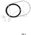
- Fig. 3 shows a mast 2 with different means for pressing the walls away from each other.
- the rotary members press the walls 6 away from each other, whereby the play is eliminated or minimised.
- An actuator (not shown) is used for providing the rotational movement of the rotary means.
- Fig. 4 shows a mast 2 with different means for pressing the walls away from each other.
- the direction forward F and the direction back T are parallel with the longitudinal axis 18 of the telescoping sections.
- the displacing means 32 may be displaced in forward direction F and in backward direction T.
- By moving the displacing means 32 forward the walls 6 are pressed away from each other. Hereby play is eliminated or minimised.
Landscapes
- Engineering & Computer Science (AREA)
- General Engineering & Computer Science (AREA)
- Mechanical Engineering (AREA)
- Transmission Devices (AREA)
- Mutual Connection Of Rods And Tubes (AREA)
- Joints Allowing Movement (AREA)
- Support Of Aerials (AREA)
- Forklifts And Lifting Vehicles (AREA)
- Actuator (AREA)
Description
- The present invention concerns a telescopic mast including two or more cylindric telescoping sections with parallel walls, where the distal one of two adjacent telescoping sections is narrower than the proximal one of the two adjacent telescoping sections, so that the distal telescoping section can be moved into and out of the proximal telescoping section, respectively, wherein in the interspace between two adjacent telescoping sections there is provided at least one means interacting with an actuator and pressing the adjacent walls away from each other.
- There are many kinds of telescopic masts of which some can be extended automatically. In connection with telescoping masts, e.g. for military use, there are special requirements to stability and accuracy.
US 4,151,534 describe a free-standing mast for an antenna including a number of telescoping tubes.US 4,137,535 describe a telescopic mast which is controlled pneumatically. The mast includes a number of telescoping tubes that may be collapsed in a base section. A piston is integrated in each section.WO 0189981 - Moreover a telescopic mast as mentioned in the introductory paragraph is know from
EP 0 730 098 A1 which discloses two collars having cam surfaces and which are rotated around their common axis in relation to each other in order to establish a clamping force and fromUS 6,152,638 A in which two wedge shaped members are interacting when they are mutually displaced in order to establish a clamping force. - None of these inventions are adequately fulfilling the requirements to stability and accuracy.
- Telescopic masts can be very high and may be used for sensors and weapons as well as for pointing out targets. High telescopic masts contain many telescoping sections. As play occurs between all adjacent telescoping sections of the mast, the play will accumulate in connection with high masts. Therefore, not the least in connection with high telescopic masts, it will very appropriate to minimise the play occurring between adjacent telescoping sections.
- The object of the present invention is to provide a telescopic mast where the play between the telescoping sections is minimised. It is a further object of the invention to provide a telescopic mast that may be positioned with great accuracy.
- According to the present invention, this is achieved with a telescopic mast including two or more cylindric telescoping sections with parallel walls, where the distal one of two adjacent telescoping sections is narrower than the proximal one of the two adjacent telescoping sections, so that the distal telescoping section can be moved into and out of the proximal telescoping section, respectively, wherein in the interspace between two adjacent telescoping sections there is provided at least one means that interacts with an actuator and presses the adjacent walls away from each other where the telescopic mast is peculiar in that the means is a rotary means interacting with an actuator which during use rotates the rotary means about an axis which is largely perpendicular to the longitudinal axis of the telescoping sections.
- By a telescopic mast according to the invention is thus achieved a number of advantages, as the means pressing the adjacent walls away from each other minimises the play occurring between adjacent telescoping sections. By pressing the adjacent walls away from each other, the play is eliminated or minimised.
- The telescopic mast is advantageous as it enables using a rotary means which is elongated and has large contact surface, thereby enabling the provision of a continuous action on the walls in direction away from each other. It may be advantageous to use a rotary means which is slightly asymmetrical and/or in which the axis of rotation is displaced in relation to the central part of the means. Hereby is provided the possibility of positional variation of the areas on the means which are in contact with the walls. The rotary means may advantageously be covered by a friction reducing material, e.g. Teflon, in order to minimise friction and wear.
- According to a specific embodiment, the telescopic mast according to the invention is peculiar in that there is used at least three rotary means and/or rotary members and/or displacing means. It will be suitable to distribute them with approximately the same mutual spacing so that adjacent telescoping sections are secured in a concentric position. Three rotary means and/or rotary members and/or displacing means are the lowest number that can ensure the securing of the adjacent telescoping sections in concentric position.
- According to a further embodiment, the telescopic mast according to the invention is peculiar in that a pipe is provided within the telescoping sections. Such an embodiment will enable the carrying of power cables, liquid, gas or other matter through the pipes. Power cables will often be required to power central parts, such as actuators, or other equipment disposed along the telescoping sections or at the top of the mast.
- Means of different nature with regard to design as well as material may be used. It may be advantageous to make the means of materials that are dimensionally stable in connection with large temperature fluctuations. It may furthermore be advantageous to coat the means with a layer of friction reducing material, as e.g. Teflon, for minimising friction between and wear of the elements involved.
- It is possible to provide a telescopic mast in which a combination of a plurality of different means for pressing the walls away from each other is used.
- Thus is it possible to combine the rotary means which rotates about the axis perpendicular to the longitudinal axis of the telescoping sections with:
- A rotary member interacting with an actuator which during use rotates the rotary member about an axis which is largely parallel with the longitudinal axis of the telescoping sections. This enables using a long rotary means having a large contact surface. A continuous action on the walls in direction away from each other may hereby be effected. It may be advantageous to use a rotary means which is slightly asymmetrical and/or in which the axis of rotation is displaced with regard to the central part of the means, as the possibility of varying the location of the areas on the means which are in contact with the walls is hereby provided. The rotary member may advantageously be covered by a friction reducing material, e.g. Teflon, in order to minimise friction between and wear of the members which are in mutual physical contact.
- Displacing means interacting with an actuator which during use displaces the displacing means in forward direction for pressing the walls away from each other. This enables using a play reducing member which does not have to be rotated. The displacing means may be designed as a cone or have other shapes. However, it is suitable to use a displacing means which is gradually tapered in forward direction, so that displacement in forward direction will gradually press the walls away from each other more and more. The displacing means may advantageously be covered by a friction reducing material, e.g. Teflon, in order to minimise friction between and wear of the members which are in mutual physical contact.
- The used actuators may e.g. be electric or pneumatic.
- The invention will in the following be explained more closely with reference to the accompanying drawing, wherein:
- Fig. 1
- shows a cross-sectional view (in longitudinal direction of the mast) of a mast according to the invention, as seen from the front;
- Fig. 2
- shows a cross-sectional view (perpendicular to longitudinal direction of the mast) of a mast according to the invention;
- Fig. 3
- shows a cross-sectional view (perpendicular to longitudinal direction of the mast) of different means for pressing the walls away from each other; and
- Fig. 4
- shows a cross-sectional view (in longitudinal direction of the mast) of different means for pressing the walls away from each other.
- In the following description, identical or corresponding elements in the various embodiments will be provided with the same designations below.
-
Fig. 1 shows a general construction of amast 2 according to the invention. Themast 2 includes threecylindric telescoping sections 4 withwalls 6. Anouter guide 26 is provided at the outer sides of the walls, near the proximal end of eachtelescoping section 4. Also, an inner 24 is provided at the inner side of thewalls 6 near the distal end of the walls. A means 10 interacting with an actuator 16 is provided in theinterspace 8 between twoadjacent telescoping sections 6. The actuator 16 is connected to apipe 28 running through the inner cavity 3 of the telescoping sections. Electric power cables (not shown) run inside thepipe 28. Thelongitudinal axis 18 of the telescoping sections is indicated. During use, themeans 10 presses thewalls 6 away from each other, whereby the play is eliminated or minimised. Advantageously, there may be used three or more means 10 for pressing thewalls 6 away from each other at several points. Adjacent telescoping sections are hereby secured in a concentric position. Theguides -
Fig. 2 shows a specific embodiment of amast 2 according to the invention. On the Figure appears two circular cylindric telescoping sections withwalls 6, where in the space between the telescoping sections there are provided three rotary means 12 which can rotate about an axis 14 which is standing perpendicularly to the longitudinal axis (not shown) of the telescoping sections. During use, the rotary means 12 presses thewalls 6 away from each other, whereby the play is eliminated or minimised. An actuator (not shown) is used for providing the rotational movement of the rotary means. -
Fig. 3 shows amast 2 with different means for pressing the walls away from each other. On the Figure appears two circular, cylindric telescoping sections withwalls 6, where in the space between the telescoping sections there are provided threerotary members 22 which can rotate about anaxis 20 situated in parallel with the longitudinal axis of the telescoping sections. During use, the rotary members press thewalls 6 away from each other, whereby the play is eliminated or minimised. An actuator (not shown) is used for providing the rotational movement of the rotary means. -
Fig. 4 shows amast 2 with different means for pressing the walls away from each other. On the Figure appears two circular,cylindric telescoping sections 4 withwalls 6, where in the space between thetelescoping sections 8 there is provided a displacing means 32 which is connected to anactuator 34. The direction forward F and the direction back T are parallel with thelongitudinal axis 18 of the telescoping sections. By means of theactuator 34, the displacing means 32 may be displaced in forward direction F and in backward direction T. By moving the displacing means 32 forward, thewalls 6 are pressed away from each other. Hereby play is eliminated or minimised.
Claims (3)
- A telescopic mast (2) including two or more cylindric telescoping sections (4) with parallel walls (6), where the distal one of two adjacent telescoping sections (4) is narrower than the proximal one of the two adjacent telescoping sections (4), so that the distal telescoping section (4) can be moved into and out of the proximal telescoping section (4), respectively, wherein in the interspace (8) between two adjacent telescoping sections (4) there is provided at least one means (10) interacting with an actuator (16) and pressing the adjacent walls (6) away from each other, characterised in that the means (10) is a rotary means (12) interacting with an actuator (16) which during use rotates the rotary means (12) about an axis (14) which is largely perpendicular to the longitudinal axis (18) of the telescoping sections.
- Telescopic mast according to claim 1, characterised in that at least three of the above mentioned means (12) are applied.
- Telescopic mast according to claim 1 or 2, characterised in that a pipe (28) is provided inside the telescoping sections (30).
Applications Claiming Priority (2)
| Application Number | Priority Date | Filing Date | Title |
|---|---|---|---|
| DK200601150A DK176810B1 (en) | 2006-09-07 | 2006-09-07 | Telescopic mast with reduced veil |
| PCT/DK2007/000401 WO2008028490A1 (en) | 2006-09-07 | 2007-09-07 | Telescopic mast having reduced play |
Publications (3)
| Publication Number | Publication Date |
|---|---|
| EP2070153A1 EP2070153A1 (en) | 2009-06-17 |
| EP2070153A4 EP2070153A4 (en) | 2016-03-09 |
| EP2070153B1 true EP2070153B1 (en) | 2019-07-03 |
Family
ID=39156839
Family Applications (1)
| Application Number | Title | Priority Date | Filing Date |
|---|---|---|---|
| EP07801369.5A Not-in-force EP2070153B1 (en) | 2006-09-07 | 2007-09-07 | Telescopic mast having reduced play |
Country Status (7)
| Country | Link |
|---|---|
| US (1) | US8695286B2 (en) |
| EP (1) | EP2070153B1 (en) |
| JP (1) | JP2010502916A (en) |
| AU (1) | AU2007294294B2 (en) |
| CA (1) | CA2662438C (en) |
| DK (2) | DK176810B1 (en) |
| WO (1) | WO2008028490A1 (en) |
Families Citing this family (12)
| Publication number | Priority date | Publication date | Assignee | Title |
|---|---|---|---|---|
| PT2147174T (en) * | 2007-04-16 | 2017-09-22 | Falck Schmidt Defence Systems As | Telescoping mast |
| US8302365B2 (en) * | 2010-02-25 | 2012-11-06 | Gee Anthony F | Partially self-erecting wind turbine tower |
| DK177708B1 (en) | 2012-09-06 | 2014-03-24 | Falck Schmidt Defence Systems As | A telescopic mast |
| US9441761B2 (en) * | 2014-11-06 | 2016-09-13 | Raytheon Company | Telescoping mast cable management system |
| US10355468B2 (en) * | 2015-08-14 | 2019-07-16 | Tim Price, Inc. | Cable management spiral |
| US10455435B2 (en) * | 2016-09-08 | 2019-10-22 | Commscope Technologies Llc | Mobile site platform with descending capability |
| US10723607B2 (en) * | 2017-03-24 | 2020-07-28 | Big Lift, Llc | Electric personnel lift device |
| US10337650B2 (en) * | 2017-04-20 | 2019-07-02 | Mobile Tech, Inc. | Cable management system for telescoping assembly |
| DK179982B1 (en) * | 2018-05-01 | 2019-12-03 | Falck-Schmidt Jan | Telescopic Mast |
| FR3081841B1 (en) * | 2018-05-29 | 2021-05-14 | Arianegroup Sas | DEPLOYABLE CARRIER DEVICE FOR SATELLITE EQUIPMENT |
| CA3074528A1 (en) | 2019-03-13 | 2020-09-13 | Armstrong World Industries, Inc. | Dimensionally stable building panel |
| FR3164492A1 (en) * | 2024-07-11 | 2026-01-16 | Edma | Lifting mechanism for a construction plate lifting device, lifting device incorporating such a mechanism, lifting method using such a device. |
Family Cites Families (37)
| Publication number | Priority date | Publication date | Assignee | Title |
|---|---|---|---|---|
| US1319943A (en) * | 1919-10-28 | Collapsible towes | ||
| US815594A (en) * | 1904-05-18 | 1906-03-20 | Janko Kovacevic | Telescopic elevator. |
| US2128712A (en) * | 1936-09-22 | 1938-08-30 | Ed Mims | Portable gin pole |
| US2617933A (en) | 1949-01-21 | 1952-11-11 | Casco Products Corp | Automobile antenna |
| US3624979A (en) * | 1969-08-25 | 1971-12-07 | Daniel F Przybylski | Telescoping hydraulic cylinder arrangement for multiple section extensible booms |
| CA904530A (en) * | 1969-10-10 | 1972-07-11 | R. Hayes John | Telescopic structure assemblies |
| US3738075A (en) * | 1971-06-16 | 1973-06-12 | Nat Crane Corp | Extendible boom with latch means for extension and retraction |
| US3737134A (en) * | 1971-06-18 | 1973-06-05 | Afco Manuf Corp | Telescoping support column |
| US3724885A (en) * | 1972-01-07 | 1973-04-03 | G Becker | Locking device for extensible tubes |
| DE2603488C3 (en) * | 1976-01-30 | 1979-02-22 | Dornier System Gmbh, 7990 Friedrichshafen | Telescopically variable-length device, in particular boom support arm or the like, e.g. for remote-controlled devices, in particular for space technology |
| DE7629017U1 (en) | 1976-09-17 | 1977-04-07 | Rupprecht, Walter, 6464 Linsengericht | TELESCOPIC ANTENNA MAST |
| US4151534A (en) | 1977-09-14 | 1979-04-24 | Bond Orville R | Antenna telescoping tower |
| US4172913A (en) * | 1977-09-23 | 1979-10-30 | Ballah Clark A | Artificial Christmas tree structure |
| US4513938A (en) * | 1981-08-28 | 1985-04-30 | Seymour Charles M | Retracting refuse can support |
| DE3611810C2 (en) * | 1986-04-08 | 1987-03-05 | Geroh GmbH Mechanische Systeme, 8551 Waischenfeld | Telescopic mast |
| DE3630746C1 (en) * | 1986-09-10 | 1988-02-11 | Dornier Gmbh | Retaining device for elements of a telescopic, length-variable device |
| US5035094A (en) * | 1990-03-26 | 1991-07-30 | Legare David J | Nested extension/retraction structure and method of fabrication |
| JP2652592B2 (en) * | 1991-05-17 | 1997-09-10 | 日本スカイロボット株式会社 | Retractable mechanism such as telescopic columns |
| US5218375A (en) | 1991-11-15 | 1993-06-08 | Antenna Products Corporation | Rapidly extendible and retractable antenna mast |
| US5234187A (en) * | 1992-06-02 | 1993-08-10 | Steelcase Inc. | Chair height adjustment mechanism |
| US5333422A (en) * | 1992-12-02 | 1994-08-02 | The United States Of America As Represented By The United States Department Of Energy | Lightweight extendable and retractable pole |
| US5537125A (en) * | 1994-09-29 | 1996-07-16 | Lba Technology, Inc. | Telescoping tower |
| US5492430A (en) * | 1994-10-14 | 1996-02-20 | Carl A. Hammoms | Telescopic tubes locking device |
| GB9504291D0 (en) * | 1995-03-03 | 1995-04-19 | Bartingale Peter | Improvements in adjustable clamping between two tubes |
| US5660495A (en) * | 1995-11-02 | 1997-08-26 | Japan Skyrobot Co., Ltd | Locking-unlocking mechanism for telescopic device |
| GB9608945D0 (en) | 1996-04-29 | 1996-07-03 | Vitec Group Plc | Improvements in or relating to extendible legs for stands or similar appliances |
| US6299113B1 (en) * | 1998-12-18 | 2001-10-09 | Koyo Giken Co., Ltd. | Telescopic member, cylindrical body and molded body |
| AU2001260086B2 (en) | 2000-05-22 | 2005-04-14 | Ideassociates (Iom) Limited | Telescopically moving structure |
| US6361002B1 (en) * | 2000-11-22 | 2002-03-26 | Kun-Chia Cheng | Telescoping rod |
| US6767115B2 (en) * | 2001-11-16 | 2004-07-27 | The Will-Burt Company | Pneumatic telescoping mast |
| GB2386579B (en) * | 2002-03-22 | 2004-08-25 | Shang Gu Entpr Co Ltd | Locking mechanism for telescopic tube |
| AU2003302651A1 (en) * | 2002-11-29 | 2004-06-23 | Nsk Ltd. | Telescoping shaft for vehicle steering |
| CA2415982C (en) * | 2003-01-09 | 2008-11-18 | Industries Mailhot Inc. | A bore sealing telescopic hoist |
| US7914238B2 (en) * | 2004-09-20 | 2011-03-29 | Anthony John Spencer Spearing | Free standing support |
| US20060207210A1 (en) * | 2005-03-10 | 2006-09-21 | Kroeger E B | Support column collet assembly |
| JP4921762B2 (en) * | 2005-09-30 | 2012-04-25 | 株式会社ジェイテクト | Telescopic shaft and telescopic shaft for vehicle steering |
| US7845602B1 (en) * | 2006-02-09 | 2010-12-07 | Primos, Inc. | Telescoping support stand apparatus |
-
2006
- 2006-09-07 DK DK200601150A patent/DK176810B1/en not_active IP Right Cessation
-
2007
- 2007-09-07 EP EP07801369.5A patent/EP2070153B1/en not_active Not-in-force
- 2007-09-07 US US12/439,862 patent/US8695286B2/en active Active
- 2007-09-07 CA CA2662438A patent/CA2662438C/en not_active Expired - Fee Related
- 2007-09-07 JP JP2009527016A patent/JP2010502916A/en active Pending
- 2007-09-07 DK DK07801369.5T patent/DK2070153T3/en active
- 2007-09-07 AU AU2007294294A patent/AU2007294294B2/en not_active Ceased
- 2007-09-07 WO PCT/DK2007/000401 patent/WO2008028490A1/en not_active Ceased
Non-Patent Citations (1)
| Title |
|---|
| None * |
Also Published As
| Publication number | Publication date |
|---|---|
| EP2070153A4 (en) | 2016-03-09 |
| DK200601150A (en) | 2008-03-08 |
| CA2662438A1 (en) | 2008-03-13 |
| US8695286B2 (en) | 2014-04-15 |
| DK176810B1 (en) | 2009-10-12 |
| WO2008028490A1 (en) | 2008-03-13 |
| AU2007294294B2 (en) | 2012-05-17 |
| CA2662438C (en) | 2015-03-24 |
| JP2010502916A (en) | 2010-01-28 |
| AU2007294294A1 (en) | 2008-03-13 |
| DK2070153T3 (en) | 2019-08-12 |
| US20100050557A1 (en) | 2010-03-04 |
| EP2070153A1 (en) | 2009-06-17 |
Similar Documents
| Publication | Publication Date | Title |
|---|---|---|
| US8695286B2 (en) | Telescopic mast having reduced play | |
| EP1884445A3 (en) | Adjustable energy absorbing device for a collapsible steering column | |
| US9057225B2 (en) | Apparatus for releasably holding a pipe, rod or the like | |
| EP0202206B1 (en) | Robot | |
| US20100313695A1 (en) | Device for a body's spherical motion control | |
| JP5060984B2 (en) | Friction welding equipment | |
| JP2005507679A5 (en) | ||
| US7567854B2 (en) | Self structuring and computing system | |
| US9222557B2 (en) | Dual-screw linear actuator | |
| AU2008238435B2 (en) | Telescoping mast | |
| US20160221197A1 (en) | Robotic Arm and Wrist Mechanisms | |
| US20140097629A1 (en) | Integrated Two Dimensional Robotic Palm for Variable Pitch Positioning of Multiple Transfer Devices | |
| EP2824274A3 (en) | Microtunneling system and apparatus | |
| US8047094B2 (en) | Hydraulic involute cam actuator | |
| US20180135794A1 (en) | Extendable cage telescopic system | |
| EP3587862B1 (en) | Telescopic adjuster | |
| WO2010144367A1 (en) | Spherical gear and gear system comprising such a spherical gear | |
| SE515548C2 (en) | Industrial robot with an arm system according to the delta concept and procedure for manufacturing an industrial robot and use | |
| CA2559676A1 (en) | Borehole tool | |
| CN107889475A (en) | Lathe for workpieces processing | |
| US12036658B2 (en) | Device for supporting a load | |
| JP2022540196A5 (en) | ||
| US8137092B2 (en) | Support assembly for an extruder | |
| JP2010221342A (en) | Industrial robot | |
| CN111894809A (en) | Assembling tool and assembling method |
Legal Events
| Date | Code | Title | Description |
|---|---|---|---|
| PUAI | Public reference made under article 153(3) epc to a published international application that has entered the european phase |
Free format text: ORIGINAL CODE: 0009012 |
|
| 17P | Request for examination filed |
Effective date: 20090403 |
|
| AK | Designated contracting states |
Kind code of ref document: A1 Designated state(s): AT BE BG CH CY CZ DE DK EE ES FI FR GB GR HU IE IS IT LI LT LU LV MC MT NL PL PT RO SE SI SK TR |
|
| AX | Request for extension of the european patent |
Extension state: AL BA HR MK RS |
|
| DAX | Request for extension of the european patent (deleted) | ||
| RA4 | Supplementary search report drawn up and despatched (corrected) |
Effective date: 20160208 |
|
| RIC1 | Information provided on ipc code assigned before grant |
Ipc: H01Q 1/10 20060101ALI20160202BHEP Ipc: H01Q 1/12 20060101AFI20160202BHEP Ipc: F16B 7/14 20060101ALI20160202BHEP |
|
| 19U | Interruption of proceedings before grant |
Effective date: 20171003 |
|
| 19W | Proceedings resumed before grant after interruption of proceedings |
Effective date: 20181203 |
|
| RAP1 | Party data changed (applicant data changed or rights of an application transferred) |
Owner name: DRS SUSTAINMENT SYSTEMS, INC. |
|
| GRAP | Despatch of communication of intention to grant a patent |
Free format text: ORIGINAL CODE: EPIDOSNIGR1 |
|
| STAA | Information on the status of an ep patent application or granted ep patent |
Free format text: STATUS: GRANT OF PATENT IS INTENDED |
|
| INTG | Intention to grant announced |
Effective date: 20190124 |
|
| GRAS | Grant fee paid |
Free format text: ORIGINAL CODE: EPIDOSNIGR3 |
|
| GRAA | (expected) grant |
Free format text: ORIGINAL CODE: 0009210 |
|
| STAA | Information on the status of an ep patent application or granted ep patent |
Free format text: STATUS: THE PATENT HAS BEEN GRANTED |
|
| AK | Designated contracting states |
Kind code of ref document: B1 Designated state(s): AT BE BG CH CY CZ DE DK EE ES FI FR GB GR HU IE IS IT LI LT LU LV MC MT NL PL PT RO SE SI SK TR |
|
| REG | Reference to a national code |
Ref country code: GB Ref legal event code: FG4D |
|
| REG | Reference to a national code |
Ref country code: CH Ref legal event code: EP Ref country code: AT Ref legal event code: REF Ref document number: 1152090 Country of ref document: AT Kind code of ref document: T Effective date: 20190715 |
|
| REG | Reference to a national code |
Ref country code: IE Ref legal event code: FG4D |
|
| REG | Reference to a national code |
Ref country code: DE Ref legal event code: R096 Ref document number: 602007058748 Country of ref document: DE |
|
| REG | Reference to a national code |
Ref country code: DK Ref legal event code: T3 Effective date: 20190808 |
|
| REG | Reference to a national code |
Ref country code: NL Ref legal event code: MP Effective date: 20190703 |
|
| REG | Reference to a national code |
Ref country code: LT Ref legal event code: MG4D |
|
| REG | Reference to a national code |
Ref country code: AT Ref legal event code: MK05 Ref document number: 1152090 Country of ref document: AT Kind code of ref document: T Effective date: 20190703 |
|
| PG25 | Lapsed in a contracting state [announced via postgrant information from national office to epo] |
Ref country code: BG Free format text: LAPSE BECAUSE OF FAILURE TO SUBMIT A TRANSLATION OF THE DESCRIPTION OR TO PAY THE FEE WITHIN THE PRESCRIBED TIME-LIMIT Effective date: 20191003 Ref country code: NL Free format text: LAPSE BECAUSE OF FAILURE TO SUBMIT A TRANSLATION OF THE DESCRIPTION OR TO PAY THE FEE WITHIN THE PRESCRIBED TIME-LIMIT Effective date: 20190703 Ref country code: CZ Free format text: LAPSE BECAUSE OF FAILURE TO SUBMIT A TRANSLATION OF THE DESCRIPTION OR TO PAY THE FEE WITHIN THE PRESCRIBED TIME-LIMIT Effective date: 20190703 Ref country code: PT Free format text: LAPSE BECAUSE OF FAILURE TO SUBMIT A TRANSLATION OF THE DESCRIPTION OR TO PAY THE FEE WITHIN THE PRESCRIBED TIME-LIMIT Effective date: 20191104 Ref country code: AT Free format text: LAPSE BECAUSE OF FAILURE TO SUBMIT A TRANSLATION OF THE DESCRIPTION OR TO PAY THE FEE WITHIN THE PRESCRIBED TIME-LIMIT Effective date: 20190703 Ref country code: FI Free format text: LAPSE BECAUSE OF FAILURE TO SUBMIT A TRANSLATION OF THE DESCRIPTION OR TO PAY THE FEE WITHIN THE PRESCRIBED TIME-LIMIT Effective date: 20190703 Ref country code: LT Free format text: LAPSE BECAUSE OF FAILURE TO SUBMIT A TRANSLATION OF THE DESCRIPTION OR TO PAY THE FEE WITHIN THE PRESCRIBED TIME-LIMIT Effective date: 20190703 Ref country code: SE Free format text: LAPSE BECAUSE OF FAILURE TO SUBMIT A TRANSLATION OF THE DESCRIPTION OR TO PAY THE FEE WITHIN THE PRESCRIBED TIME-LIMIT Effective date: 20190703 |
|
| PG25 | Lapsed in a contracting state [announced via postgrant information from national office to epo] |
Ref country code: ES Free format text: LAPSE BECAUSE OF FAILURE TO SUBMIT A TRANSLATION OF THE DESCRIPTION OR TO PAY THE FEE WITHIN THE PRESCRIBED TIME-LIMIT Effective date: 20190703 Ref country code: LV Free format text: LAPSE BECAUSE OF FAILURE TO SUBMIT A TRANSLATION OF THE DESCRIPTION OR TO PAY THE FEE WITHIN THE PRESCRIBED TIME-LIMIT Effective date: 20190703 Ref country code: IS Free format text: LAPSE BECAUSE OF FAILURE TO SUBMIT A TRANSLATION OF THE DESCRIPTION OR TO PAY THE FEE WITHIN THE PRESCRIBED TIME-LIMIT Effective date: 20191103 Ref country code: GR Free format text: LAPSE BECAUSE OF FAILURE TO SUBMIT A TRANSLATION OF THE DESCRIPTION OR TO PAY THE FEE WITHIN THE PRESCRIBED TIME-LIMIT Effective date: 20191004 |
|
| PG25 | Lapsed in a contracting state [announced via postgrant information from national office to epo] |
Ref country code: TR Free format text: LAPSE BECAUSE OF FAILURE TO SUBMIT A TRANSLATION OF THE DESCRIPTION OR TO PAY THE FEE WITHIN THE PRESCRIBED TIME-LIMIT Effective date: 20190703 |
|
| REG | Reference to a national code |
Ref country code: DE Ref legal event code: R119 Ref document number: 602007058748 Country of ref document: DE |
|
| PG25 | Lapsed in a contracting state [announced via postgrant information from national office to epo] |
Ref country code: IT Free format text: LAPSE BECAUSE OF FAILURE TO SUBMIT A TRANSLATION OF THE DESCRIPTION OR TO PAY THE FEE WITHIN THE PRESCRIBED TIME-LIMIT Effective date: 20190703 Ref country code: PL Free format text: LAPSE BECAUSE OF FAILURE TO SUBMIT A TRANSLATION OF THE DESCRIPTION OR TO PAY THE FEE WITHIN THE PRESCRIBED TIME-LIMIT Effective date: 20190703 Ref country code: EE Free format text: LAPSE BECAUSE OF FAILURE TO SUBMIT A TRANSLATION OF THE DESCRIPTION OR TO PAY THE FEE WITHIN THE PRESCRIBED TIME-LIMIT Effective date: 20190703 Ref country code: RO Free format text: LAPSE BECAUSE OF FAILURE TO SUBMIT A TRANSLATION OF THE DESCRIPTION OR TO PAY THE FEE WITHIN THE PRESCRIBED TIME-LIMIT Effective date: 20190703 |
|
| PGFP | Annual fee paid to national office [announced via postgrant information from national office to epo] |
Ref country code: DK Payment date: 20200310 Year of fee payment: 13 |
|
| PG25 | Lapsed in a contracting state [announced via postgrant information from national office to epo] |
Ref country code: MC Free format text: LAPSE BECAUSE OF FAILURE TO SUBMIT A TRANSLATION OF THE DESCRIPTION OR TO PAY THE FEE WITHIN THE PRESCRIBED TIME-LIMIT Effective date: 20190703 Ref country code: IS Free format text: LAPSE BECAUSE OF FAILURE TO SUBMIT A TRANSLATION OF THE DESCRIPTION OR TO PAY THE FEE WITHIN THE PRESCRIBED TIME-LIMIT Effective date: 20200224 Ref country code: SK Free format text: LAPSE BECAUSE OF FAILURE TO SUBMIT A TRANSLATION OF THE DESCRIPTION OR TO PAY THE FEE WITHIN THE PRESCRIBED TIME-LIMIT Effective date: 20190703 |
|
| REG | Reference to a national code |
Ref country code: CH Ref legal event code: PL |
|
| PLBE | No opposition filed within time limit |
Free format text: ORIGINAL CODE: 0009261 |
|
| STAA | Information on the status of an ep patent application or granted ep patent |
Free format text: STATUS: NO OPPOSITION FILED WITHIN TIME LIMIT |
|
| PG2D | Information on lapse in contracting state deleted |
Ref country code: IS |
|
| PG25 | Lapsed in a contracting state [announced via postgrant information from national office to epo] |
Ref country code: CH Free format text: LAPSE BECAUSE OF NON-PAYMENT OF DUE FEES Effective date: 20190930 Ref country code: DE Free format text: LAPSE BECAUSE OF NON-PAYMENT OF DUE FEES Effective date: 20200401 Ref country code: LU Free format text: LAPSE BECAUSE OF NON-PAYMENT OF DUE FEES Effective date: 20190907 Ref country code: LI Free format text: LAPSE BECAUSE OF NON-PAYMENT OF DUE FEES Effective date: 20190930 Ref country code: IE Free format text: LAPSE BECAUSE OF NON-PAYMENT OF DUE FEES Effective date: 20190907 |
|
| REG | Reference to a national code |
Ref country code: BE Ref legal event code: MM Effective date: 20190930 |
|
| 26N | No opposition filed |
Effective date: 20200603 |
|
| PG25 | Lapsed in a contracting state [announced via postgrant information from national office to epo] |
Ref country code: BE Free format text: LAPSE BECAUSE OF NON-PAYMENT OF DUE FEES Effective date: 20190930 Ref country code: SI Free format text: LAPSE BECAUSE OF FAILURE TO SUBMIT A TRANSLATION OF THE DESCRIPTION OR TO PAY THE FEE WITHIN THE PRESCRIBED TIME-LIMIT Effective date: 20190703 |
|
| GBPC | Gb: european patent ceased through non-payment of renewal fee |
Effective date: 20191003 |
|
| PG25 | Lapsed in a contracting state [announced via postgrant information from national office to epo] |
Ref country code: FR Free format text: LAPSE BECAUSE OF NON-PAYMENT OF DUE FEES Effective date: 20190930 Ref country code: GB Free format text: LAPSE BECAUSE OF NON-PAYMENT OF DUE FEES Effective date: 20191003 |
|
| REG | Reference to a national code |
Ref country code: DK Ref legal event code: EBP Effective date: 20200930 |
|
| PG25 | Lapsed in a contracting state [announced via postgrant information from national office to epo] |
Ref country code: CY Free format text: LAPSE BECAUSE OF FAILURE TO SUBMIT A TRANSLATION OF THE DESCRIPTION OR TO PAY THE FEE WITHIN THE PRESCRIBED TIME-LIMIT Effective date: 20190703 |
|
| PG25 | Lapsed in a contracting state [announced via postgrant information from national office to epo] |
Ref country code: HU Free format text: LAPSE BECAUSE OF FAILURE TO SUBMIT A TRANSLATION OF THE DESCRIPTION OR TO PAY THE FEE WITHIN THE PRESCRIBED TIME-LIMIT; INVALID AB INITIO Effective date: 20070907 Ref country code: MT Free format text: LAPSE BECAUSE OF FAILURE TO SUBMIT A TRANSLATION OF THE DESCRIPTION OR TO PAY THE FEE WITHIN THE PRESCRIBED TIME-LIMIT Effective date: 20190703 |
|
| PG25 | Lapsed in a contracting state [announced via postgrant information from national office to epo] |
Ref country code: DK Free format text: LAPSE BECAUSE OF NON-PAYMENT OF DUE FEES Effective date: 20200930 |