EP2069852B1 - Sports-specific shield - Google Patents
Sports-specific shield Download PDFInfo
- Publication number
- EP2069852B1 EP2069852B1 EP07751338.0A EP07751338A EP2069852B1 EP 2069852 B1 EP2069852 B1 EP 2069852B1 EP 07751338 A EP07751338 A EP 07751338A EP 2069852 B1 EP2069852 B1 EP 2069852B1
- Authority
- EP
- European Patent Office
- Prior art keywords
- frame
- eyeglass
- lens
- nosepiece
- post
- Prior art date
- Legal status (The legal status is an assumption and is not a legal conclusion. Google has not performed a legal analysis and makes no representation as to the accuracy of the status listed.)
- Active
Links
Images


Classifications
-
- G—PHYSICS
- G02—OPTICS
- G02C—SPECTACLES; SUNGLASSES OR GOGGLES INSOFAR AS THEY HAVE THE SAME FEATURES AS SPECTACLES; CONTACT LENSES
- G02C1/00—Assemblies of lenses with bridges or browbars
- G02C1/04—Bridge or browbar secured to or integral with partial rims, e.g. with partially-flexible rim for holding lens
-
- G—PHYSICS
- G02—OPTICS
- G02C—SPECTACLES; SUNGLASSES OR GOGGLES INSOFAR AS THEY HAVE THE SAME FEATURES AS SPECTACLES; CONTACT LENSES
- G02C5/00—Constructions of non-optical parts
- G02C5/12—Nose pads; Nose-engaging surfaces of bridges or rims
- G02C5/122—Nose pads; Nose-engaging surfaces of bridges or rims with adjustable means
- G02C5/124—Nose pads; Nose-engaging surfaces of bridges or rims with adjustable means for vertically varying the position of the lenses
-
- G—PHYSICS
- G02—OPTICS
- G02C—SPECTACLES; SUNGLASSES OR GOGGLES INSOFAR AS THEY HAVE THE SAME FEATURES AS SPECTACLES; CONTACT LENSES
- G02C5/00—Constructions of non-optical parts
- G02C5/12—Nose pads; Nose-engaging surfaces of bridges or rims
- G02C5/126—Nose pads; Nose-engaging surfaces of bridges or rims exchangeable or otherwise fitted to the shape of the nose
Description
- The present invention relates generally to eyeglasses, and more particularly to a uniquely configured eyeglass shield that permits a wearer to adjust a frame thereof to provide a variety of vertical viewing angles for specific sporting applications. As discussed in greater detail below, embodiments of the present invention provide a sports-specific shield which can be selectively adjusted by the wearer in order to customize the configuration and fit of the eyeglass shield for beneficial use in specific activities, without requiring the use of tools. The resulting eyeglass shield can therefore be utilized in demanding sporting situations that require either a heads-up or heads-down posture of the wearer, such as competitive running, driving, skiing, or bicycle racing.
- Eyeglasses, and sunglasses in particular, have long been designed with the general objective of blocking the sun or other sources of bright light from one's eyes. Over time, various features and advancements in this technology have been developed. The evolution of numerous designs of dual and unitary lens glasses initially differed essentially only in aesthetic features. However, eyeglass and lens designs have further developed in response to various optical considerations such as optical clarity, resolution, field of vision, refraction, and other such qualities. Typically, the optical qualities of the lens are best when the wearer's line of sight (LOS) extends in parallel to the optical center line (OCL) the lens.
- Although these advancements in eyeglass technology have provided substantial benefits for eyeglass wearers participating in a broad range of activities, several sporting activities often require the wearer to assume body postures that displace the wearer's LOS particularly in the vertical plane from consistently being aligned with the OCL of particular lens. In addition, unique facial structures and geometries can result in different fits that similarly prevent different wearers from commonly enjoying the superior optical characteristics of a given eyeglass.
- Many sporting activities may be characterized as requiring the user to assume either a heads-up or a heads-down posture. In the heads-up posture, which is illustrated in accompanying
Figure 6A , a wearer's head is in a generally upright vertical position directly above the shoulders. Thus, the OCL of the eyeglass lenses and the wearer's LOS tend to be aligned parallel and point more or less straight ahead. Activities such as running, driving, and the like, tend to encourage a heads-up posture of the wearer. - In the heads-down posture, a wearer assumes a generally forward-leaning posture with the head extending forwardly of the torso, shown generally in
Figure 6B . In the heads-down posture, the head is tucked in an aerodynamic position with the OCL of the eyeglass lens typically being directed at the ground in front of the wearer; while the LOS is angularaly displaced upwardly with respect to the long. Thus, in order to optimize forward vision the wearer must lift their head upwardly from the racing posture, in order to bring their LOS into parallel with the OCL. The racing posture also brings the LOS high enough on conventional lenses that the upper frame can limit the field of view in the vertical plane. Activities such as bicycle racing and others commonly require the wearer to assume a heads-down posture for long periods of time. - Finally, unique facial geometries can prevent some wearers from enjoying superior optical characteristics of a given frame and lens system. A given pair of eyeglasses often fits differently on different wearers due to differences in facial structure. As a result, some wearer's straight-ahead LOS may not pass through the lens in parallel with the OCL. For example, an eyeglass that has been designed to fit a majority of wearers may nevertheless sit too high or too low on certain wearers depending on the structure and geometry of their nose and face. Therefore, the facial structure, as well as the particular activity in which the wearer is engaged, can cause the eyeglass have a particular fit on the wearer that prevents optimal vertical alignment of the OCL of the lens with the desired LOS of the wearer.
-
US 4 951 322 A discloses a detachable mono-glass sports goggles including a curved rod-like spectacle frame with two bows bilaterally connected thereto; a unitary glass having its top edge inserted into the bottom scoop channel of the spectacle frame; and a nose piece having an inverted V-shaped portion to support the unitary glass and to mount on a user's nose, a split pin for insertion through the unitary glass into the spectacle frame to firmly retain the unitary glass therebetween, and a corrugated face portion for touching of fingers to correct the position of the goggles when it is in wear. -
US 4 331 393 A discloses an ophthalmic device for use by an optometrist or the like which comprises a unique fitting eyeglass frame for use with a plurality of detachable nosepiece attachments which allows the optometrist to quickly and more properly fit each patient's nose with a nose bridge that is suitably designed for the configuration of his nose. The removable nosepiece attachments are pivotably connected to the ophthalmic frame thereby allowing a front-to-rear adjustment and lacking of the nosepiece on the ophthalmic frame. - In light of the above-mentioned deficiencies of eyeglass design, there is a need in the art for an improved eyeglass that allows a wearer to adjust the fit and/or optical orientation of the eyeglass depending on the activity in which the wearer is involved. Further, there is a need in the art for an eyeglass that can be adjusted to provide superior optical qualities that in a variety of eyeglass configurations. There is a need in the art for an adjustable eyeglass that allows the wearer to align their desired LOS with respect to the OCL of the lens and that can be used in both heads-up and heads-down activities. Furthermore, there is a need in the art for an eyeglass that can be adjusted by the wearer without tools and provides superior frontal impact resistance. Finally, there is a need in the art for an adjustable eyeglass that can be easily modified by the wearer for specific activities that is lightweight, structurally durable, and that provides easy and quick assembly and disassembly, and sufficient protection of the eyes, even in a bicycle racing posture.
- The present invention relates to an adjustable eyeglass assembly according to claim 1 and to an adjustable eyeglass frame assembly according to
claim 12. - Accordingly, in an example, an eyeglass is provided for minimizing component structural integrity and component weight without reducing the overall structural integrity of the eyeglass. The eyeglass can comprise a unitary lens, a frame, and a nosepiece. The lens can have an upper edge and a lower edge. The upper edge can have lateral indents formed at opposing ends thereof, and the lower edge can have a nosepiece opening formed therein.
- The frame can have opposing terminals and an upper groove extending at least partially along the frame. The upper groove can be sized and configured to receive the upper edge of the lens with the lateral indents of the lens being receivable into the opposing terminals of the frame. Further, the upper groove can have a cross-sectional area defined by a depth and width of the upper groove. Additionally, the frame can further have a post extending downwardly from a central portion of the frame.
- The nosepiece can have a bridge and a mounting component extending upwardly from the bridge. The nosepiece can have a lower groove extending at least partially across the bridge, and the lower groove can be sized and configured such that the lower edge of the lens is receivable therein. The mounting component can be attachable to the post for attaching the nosepiece to the frame. In such an example, the cooperative engagement of the frame to the nosepiece can retain the lens therebetween for minimizing the cross-section of the upper groove without compromising overall lens retention and the overall structural integrity of the eyeglass. For example, the transverse cross-sectional area of the upper groove can be less than approximately 0.05 square inches and in some embodiments no greater than about 0.02 square inches. Further, a maximum thickness of the frame can be less than 90% of a thickness of the lens along the upper edge thereof. Thus, eyeglass weight and structural integrity of individual components can decrease while maintaining the overall structural integrity of the eyeglass.
- In another example, the post can comprises a connecting portion at a distal end thereof. Additionally, the mounting component can comprise a recess being sized and configured to receive at least the connecting portion of the post for attaching the nosepiece to the frame. The recess of the mounting component can be formed into a posterior side of the mounting component. The post can also be formed to connect to the frame posteriorly to the groove. In some examples, the post can be integrally formed with the frame. Further, the lens can be configured to be mounted anterior to the post and the mounting component of the nosepiece. Finally, an as-molded configuration of the lens can corresponds to the upper groove of the frame and the lower groove of the nosepiece.
- In accordance with yet another example, the eyeglass can be configured to be adjustable in order to minimize a vertical deviation angle of a wearer in heads-down activities. The vertical deviation angle can be defined as the angular displacement between an optical centerline of the eyeglass and an intended line of sight of the wearer. The lens of the eyeglass can define the optical centerline. In such an example, the mounting component can have a vertical height that is customizable for minimizing a desired vertical deviation angle of the wearer.
- In another example, the eyeglass can be adjustable for optimizing the protective function of the eyeglass throughout a range of vertical viewing angles, while preserving optical quality. In such an example, adjustment of the mounting component's vertical height from a first vertical height to a second vertical height can raise the height of the lens to provide protection while viewing out of the top of the eyeglass, while maintaining a desired relationship between the LOS and OCL.
- The nosepiece of the adjustable eyeglass can be selected from a plurality of nosepieces having different vertical heights. A corresponding plurality of lenses having matched vertical heights is also provided; each with an OCL in the vertical which is selected to correspond to the desired LOS for each lens-nose piece combination.
- The abovementioned and other features of the inventions disclosed herein are described below with reference to the drawings of the preferred embodiments. The illustrated embodiments are intended to illustrate, but not to limit the inventions. The drawings contain the following figures:
-
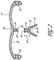
Figure 1 is a perspective exploded front view of an adjustable eyeglass having a frame, lens, and a nose piece, according to an embodiment. -
Figure 2 is a rear view of the frame and nose piece illustrated inFigure 1 . -
Figure 3A is a rear view of the eyeglass wherein the frame, lens, and nose piece are in an assembled state. -
Figure 3B is a front view of the eyeglass ofFigure 3A . -
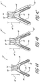
Figures 4A-4C illustrate exemplary embodiments of nosepieces wherein a post of the nosepiece has a given vertical height. -
Figure 5A is a front view of the eyeglass wherein the frame and nose piece are assembled prior to installation of the lens, according to another embodiment. -
Figure 5B is a front view of the eyeglass ofFigure 5A in an assembled state. -
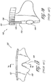
Figure 6A is a side view of the eyeglass as worn on a wearer in a heads-up posture. -
Figure 6B is a side view of the eyeglass as worn on a wearer in a heads-down posture illustrating a vertical viewing angle defined by a line of sight of the wearer and an optical centerline of the eyeglass. -
Figure 7A is a front view of a prior art eyeglass. -
Figure 7B is a side cross-sectional view of the prior art eyeglass ofFigure 7A illustrating depth of a groove within a frame of the eyeglass wherein a lens is retained. -
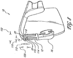
Figure 8 is a side cross-sectional view of the eyeglass ofFigure 3B , illustrating an upper groove within the frame and the interconnection of the lens with the frame. - While the present description sets forth specific details of various embodiments, it will be appreciated that the description is illustrative only and should not be construed in any way as limiting. Furthermore, various applications of such embodiments and modifications thereto, which may occur to those who are skilled in the art, are also encompassed by the general concepts described herein.
- With reference to
Figure 1 , an embodiment of a uniquely configuredeyeglass 10 is provided that can reduce the overall weight of theeyeglass 10 and improve the optical qualities enjoyed by a wearer during various heads-up and heads-down activities. Theeyeglass 10 can be manufactured from a variety of materials and methods. However, according to one of the unique aspects of the present invention, theeyeglass 10 can be assembled using lighter-weight components that may not otherwise be used due to structural strength requirements. - For example, in previous eyeglass designs, thicker, bulkier, and heavier designs have been used to provide sufficient durability and structural integrity for the
eyeglass 10. However, as described further herein, theeyeglass 10 can be formed using lighter-weight components (which consequently may have lesser structural integrity than otherwise comparable heavier-weight components) without reducing the overall structural integrity of the eyeglass. Further, embodiments also provide substantial resistance to torsional and/or bending stresses. - In addition, an embodiment of the
eyeglass 10 can also provide optimal optical characteristics to a wearer at a plurality of vertical viewing angles. As mentioned above, many sporting activities may be characterized as requiring the user to assume either a heads-up or a heads-down posture. In the heads-down posture, the wearer typically directs their desired line of sight (LOS) through an upper area of the eyeglass that may not provide the wearer of prior art glasses with the intended optimal optical qualities of the eyeglass as available when viewing in parallel to through an optical centerline (OCL) of the eyeglass. - As shown in
Figures 6A-6B , the angular divergence in theLOS 80 of the wearer with respect to theOCL 90 of theeyeglass 10 can be referred to as avertical deviation angle 92. Thevertical viewing angle 92 can also be defined as the angular displacement between theOCL 90 of theeyeglass 10 and theLOS 80 of the wearer. By reducing thevertical deviation angle 92, it is contemplated that the wearer can substantially benefit from improved optical qualities of theeyeglass 10 otherwise unavailable during typical heads-down activities and due to non-normal facial structures. - In
Figure 1 , theeyeglass 10 is illustrated as including alens 12, aframe 14, a pair of opposingearpieces 16, and anosepiece 18. These components of theeyeglass 10 can be configured as snap fit components that allow the wearer to quickly assembly or disassemble theeyeglass 10 without the use of tools. Thelens 12 can be formed in a variety of configurations and geometries. Preferably, thelens 12 is configured to be lightweight and to provide superior optical qualities throughout the field of view of the wearer. It is contemplated that thelens 12 can be formed utilizing a dual or unitary design. As shown inFigure 1 , thelens 12 has anupper edge 20 and alower edge 22. As shown inFigures 6A-6B , thelens 12 can also define the optical centerline (OCL) 90. See e.g.U.S. Patent No. 6,010,218 to Houston, et al. , entitled Decentered Corrected Lens for Eyewear, the disclosure of which is incorporated in its entirety by reference herein, particularly with respect to lens construction, design and optics. - The upper and
lower edges lens 12 can also include a pair of opposinglateral indents 24 formed in opposing side edges 28 thereof. The lateral indents 24 can be voids in the lens, and shaped in a variety of designs, as also described further below. Finally, thelens 12 can also include anosepiece opening 26 whereinto thenosepiece 18 can be at least partially received. - As shown in
Figures 1-2 , theframe 14 can be configured to comprise opposingterminals 30 and anupper groove 32, which can collectively form an upper lens receiving portion. In an embodiment, the opposingterminals 30 are sized and configured to mate with at least a portion of the respective ones of the side edges 28 of thelens 12. Preferably, theterminals 30 are formed to removably receive the respective ones of the opposinglateral indents 24 of thelens 12. - The
upper groove 32 can extend at least partially along theframe 14, and preferable extends intermediate the opposing lateral indents 30. Theupper groove 32 is preferably sized and configured to receive theupper edge 20 of thelens 12. As shown in the embodiment illustrated inFigure 8 , theupper groove 32 can define a lengthwise slot having awidth 110 and adepth 112. Theupper groove 32 can be formed having internal faces that are of differing or equal dimensions. For example, as shown inFigure 8 , arear face 114 can be of a greater cross-sectional length than aforward face 116, and can further differ from that of theupper face 118 of theupper groove 32. The rear, forward, andupper faces upper groove 32 can be modified to provide varying degrees of retention of theupper edge 20 of thelens 12 within theupper groove 32. - The opposing
terminals 30 can be formed with theupper groove 32 extending at least partially therealong. In this regard, theeyeglass 10 can be at least partially assembled with the lateral indents 24 of thelens 12 being received into the opposingterminals 30 of theframe 12 and theupper edge 20 of thelens 12 being at least partially received within theupper groove 32. As mentioned above, the lateral indents 24 of thelens 12 can be variously configured, and can include distinctive geometric patterns that tend to interlock with a corresponding geometric pattern of theterminals 30. Such a feature can tend to ensure that thelens 12 is urged to within theupper groove 32 and properly fits with theframe 14. Such a feature may also be utilized to help the wear ensure that thelens 12 is in an engaged position with theframe 14 during assembly. As such, thelens 12 can be configured to be received within theupper groove 32 for vertically securing theupper edge 20 of thelens 12, and the opposinglateral indents 24 can be received within the respective ones of the opposingterminals 30 of theframe 14 for horizontally securing thelens 12 to theframe 14. - In accordance with an embodiment, the
frame 14 can further comprise apost 34 extending downwardly from acentral portion 36 of theframe 14. Thepost 34 can be formed in a variety of geometric shapes, as described herein. Preferably, thepost 34 can be substantially rectangular in shape and of sufficient width and thickness to provide firm engagement with thenosepiece 18, as discussed further below. Thepost 34 is preferably integrally formed with theframe 14, such as being formed of a single, continuous piece of material as in injection molding. Alternatively, thepost 34 can be formed of separate a material and can be joined to theframe 14 using an adhesive, mechanical interlock, interference fit or other fastener. Finally, as shown inFigure 2 , thepost 34 can also comprise a connectingportion 38 which may be formed at adistal end 39 of thepost 34. -
Figures 1-2 also illustrate an exemplary configuration of thenosepiece 18 wherein thenosepiece 18 has abridge 40 and a mountingcomponent 42 which may extend upwardly from thebridge 40 and having avertical height 44. Thebridge 40 and the mountingcomponent 42 are preferably integrally formed, as by injection molding, but can also be formed from separate, joinable materials. - The
nosepiece 18 can further comprise alower groove 46 that is formed along at least a portion of thebridge 40. For example, thelower groove 46 can extend at least partially along thebridge 40, as shown inFigure 1 . Thelower groove 46 of thebridge 40 is preferably sized and configured to removably receive thelower edge 22 of thelens 12. In particular, thelower groove 46 can be shaped to conform to the shape and size of thenosepiece opening 26 of thelens 12. - The mounting
component 42 can be sized and configured to be attachable to thepost 34 of theframe 14. The attachment of thepost 34 to the mountingcomponent 42 can be accomplished in a variety of configurations, such as with male and female-type interlocking connections and other first and second complementary surface structures. For example, one of thepost 34 or the mountingcomponent 42 can be formed as a male-type connector that can be removably connected to a corresponding female-type connector of the other one of thepost 34 and the mountingcomponent 42. - As illustrated in
Figure 2 , aposterior side 50 of the mountingcomponent 42 can be formed to include arecess 54 into which thepost 34 can be received. In such an embodiment, theconnector portion 38 of thepost 34 can be formed to mate with therecess 54 of the mountingcomponent 42. Alternatively, an anterior side 52 of thenosepiece 18 can be configured to include therecess 54. Furthermore, it is also possible that thepost 34 could include a recess and the mountingcomponent 42 can be receivable therein. Such alternative embodiments and modifications are considered to be within the scope of the present disclosure and teachings. -
Figures 3A-3B illustrate the cooperative engagement of thelens 12,frame 14, andnosepiece 18. In such an embodiment, thepost 34 can be connected to theframe 14 posterior to theupper lens groove 32. In addition, thelens 12 can be configured to be mounted anterior to thepost 34 and the mountingcomponent 42 of thenosepiece 18. An as-molded configuration of thelens 12 can correspond to theupper groove 32 of theframe 14 and thelower groove 46 of thenosepiece 18. - The cooperative engagement provided by such an embodiment can provide significant advantages that can allow for the reduction in weight of such components without reducing the overall durability and structural integrity of the
eyeglass 10. Further, in some embodiments, due to the engagement of the side edges 28 and/orlateral indents 24 of thelens 12 with the opposingterminals 30 of theframe 14, theeyeglass 10 can withstand torsional and/or bending stresses. In this regard, it is contemplated that the engagement of the side edges 28 and/orlateral indents 24 of thelens 12 with the opposingterminals 30 of theframe 14 can further stabilize and mitigate against such torsional and bending forces commonly encountered during use of theeyeglass 10. As a result, thelens 12 can be more surely retained by theframe 14 andnosepiece 18. -
Figure 3A is a rear view of theeyeglass 10 in an assembled state, andFigure 3B is a front view thereof. As shown inFigure 3A , the mountingcomponent 42 of thenosepiece 18 is attached to thepost 34 of theframe 14 to fix the vertical relative positioning of thenosepiece 18 to theframe 14. Further, with thelens 12 installed, the mountingcomponent 42 is also illustrated as being disposed intermediate thelens 12 and thepost 34 of theframe 14 to fix the horizontal relative positioning of thenosepiece 18 relative to theframe 14, as shown inFigures 3A-3B . - During assembly, the
lens 12 can be installed after the assembly of theframe 14 andnosepiece 18, although this is not required. Once assembled, thelens 12 can therefore be cooperatively engaged by theframe 14 and thenosepiece 18, which can be held in fixed relation to each other when thelens 12 is installed. Due to the fixed relationship of theframe 14 and thenosepiece 18, the upper andlower grooves lens 12 is properly retained therein. Thus, such an embodiment can ensure maximum overall retention of thelens 12 and structural integrity of theeyeglass 10. - As mentioned above, another of the significant advantages provided by embodiments disclosed herein is the reduction, minimization, and/or elimination of the vertical deviation angle that otherwise would have been induced by positioning the upper frame at different vertical heights relative to the wearer's nose. Thus, during activities, such as bicycle racing and others that encourage a heads-down posture, the wearer can adjust the
eyeglass 10 by selectively interchanging thenosepiece 18 and mounting a corresponding lens to change the primary LOS while still allowing the wearer to enjoy the superior optical qualities of thelens 12. - Referring now to
Figures 4A-4C , rear views of various embodiments of thenosepiece 18 are illustrated. As shown therein, the mountingcomponent 42 of a first nosepiece 18' can be of a first vertical height 44', asecond nosepiece 18" can correspond to a secondvertical height 44", and athird nosepiece 18"' can correspond to a thirdvertical height 44"'. Thevertical height 44 can generally be measured from anasal apex 48 to atop end 62 of thenosepiece 18.Figures 4A-4C illustrate an exemplary group ofnosepieces 18 that can be interchangeably used in some embodiments. These illustrations are provided for illustrative purposes only, and it is contemplated that various other sizes and/or configurations of thenosepiece 18 can be provided. As discussed above, the mountingcomponent 42 can be interconnectable with thepost 34 of theframe 14. It is contemplated that the wearer can select anosepiece 18 having a specificvertical height 44 according to their needs and/or preferences. When fitted onto theeyeglass 10, the selectednosepiece 18 could thus provide a customized fit of theeyeglass 10 on the wearer. Each nosepiece is matched to a corresponding lens which has an OCL positioned in the vertical to remain substantially parallel to a wearer's intended LOS through that lens-nosepiece combination. - The
vertical heights 44 ofnosepieces 18 within a group ofavailable nosepieces 18 can lie within a given range. For example, thevertical height 44 of a given one of the nosepieces can be within a preferred range of about one inch, such as +0.75 / -0.250 inches.Height 44 may be, for example, about 0.25", 0.5", 0.75" and 1.0 inch, or two or more nosepieces may be provided with ⅛ inch increments. The range can be broadened or modified depending on the geometries of theeyeglass 10 and in light of other considerations, such as the target activity, target consumer, etc. - It is contemplated that by interchanging the
nosepiece 18 with one having a differentvertical height 44, the wearer could modify upper edge of thelens 12 relative to the wearer's nose or straight aheadLOS 80. There can be provided a progression of nosepiece sizes. Thus, the wearer can selectively customize the eyeglass 10 (and also use theeyeglass 10 for various activities) such that the vertical height of the lens and the viewing angle through the lens are optimized for a particular use, and the wearer'sLOS 80 can still pass through thelens 12 more closely to parallel to the OCL, as explained further below with reference toFigure 6A-6B . - According to another aspect illustrated in
Figures 4A-4C , thenosepiece 18 can further comprise acollar portion 56 andnose pad 58. Thenose pad 58 can comprise single or dual nose pads that are attached to or formed integrally with thenosepiece 18. Thenose pad 58 can be attached to abottom portion 60 of thenosepiece 18. Thecollar portion 56 can generally extends intermediate thenose pad 58 and thelower groove 46. In this regard, thecollar portion 56 can vary in size and configuration depending on the vertical height of the mountingcomponent 42, as illustrated in.Figures 4A-4C . - Additionally, it is contemplated that the
lower groove 46 of thenosepieces 18', 18", and 18"' can be maintained in fixed relation relative to thetop end 62 of thenosepieces 18', 18", and 18"'. In the embodiment illustrated inFigure 4A , thenose pad 58 and thelower groove 46 can be positioned generally contiguously to thenosepiece opening 26 of thelens 12 when assembled thereto. However, when thevertical viewing angle 92 is adjusted by increasing thevertical height 44, such as to thevertical height 44" or 44"' ofFigures 4B or 4C , respectively, a vertical gap can result between the vertical position of thelower groove 46 and thenose pad 58. Accordingly, thecollar portion 56 can help compensate for any such gap by filling the gap therebetween. Thecollar portion 56 can be solid, perforated, or otherwise configured. Therefore, the face and eyes of the wearer can be protected from air or other matter that could otherwise flow through such a gap. -
Figure 5A illustrates an exploded view of an embodiment of theeyeglass 10 wherein thelens 12 can be installed/engaged onto theframe 14 and thenosepiece 18. Further, when disassembling theeyeglass 10 for adjustment or repair, thelens 12 can be disengaged from theframe 14 and thenosepiece 18 without requiring that other components of theeyeglass 10 be disassembled or removed prior to the disengagement of thelens 14. The engagement and disengagement of the lens is accomplished as described herein (forward and reverse order, respectively), by inserting theupper edge 20 of thelens 12 into theupper groove 32 and the opposingterminals 30, and then inserting thelower edge 22 of thelens 12 into thelower groove 46 of thenosepiece 18. This process can be accomplished by gently bending thelens 12. Thelens 12 can snap into place when properly engaged. In this manner, the wearer can selectively adjust theeyeglass 10 to fit usinginterchangeable nosepieces 18. -
Figure 5B is a front view of theeyeglass 10 illustrating the installation and fit of a plurality ofnosepieces 18', 18", and 18"'. As discussed above, the differentvertical heights 44', 44", and 44"' (seeFigures 4A-4C ) can allow the wearer to adjust the fit of theeyeglass 10 to a corresponding elevation, thereby providing for the adjustment of thevertical viewing angle 92. The configuration of thenosepiece 18 can be modified to include any variety of sizes, shapes, nose pads, materials, collar portion configurations, and other features, and can correspond to an elevation of theeyeglass 10 on the face of the wearer, measured for example, with respect to the wearer's eyebrow. - Referring now to
Figures 6A-6B , side views are shown of a wearer's head having theeyeglass 10 thereon. InFigure 6A , the wearer's head and theeyeglass 10 is in a generally heads-up position, and theOCL 90 of thelens 12 is generally horizontal (straight ahead). Further, theLOS 80 of the wearer is also generally horizontal, and substantially parallel with theOCL 90 of thelens 12. - However, in
Figure 6B , an eyeglass 82 is illustrated in hidden lines wherein the eyeglass 82 is not adjusted to compensate for the vertically elevated (with respect to the lens)LOS 80. Thus, theLOS 80 of the wearer would pass through an upper portion of the lens of the eyeglass 82, closer to the upper frame. Such as result provides poor optical results and also inferior protection from wind, light and debris. In addition, thewearers LOS 80 could be obstructed by the frame of the eyeglass 82. In any event, with the frame of the eyeglass being so close to theLOS 80, the wearer's field of view could certainly be reduced. - In contrast,
Figure 6B also shows aneyeglass 84 wherein the vertical height of the nosepiece has been increased and a lens with a corresponding configuration has been inserted to reduce thevertical deviation angle 92 and provide superior eye protection. As shown inFigure 6B , theLOS 80 of the wearer tends to pass more closely through a central portion of the lens, and is more aligned with theOCL 90 of the lens. Such an implementation can tend to improve the overall optical qualities enjoyed by the wearer. Further, such an embodiment tends to ensure that the wearer'sLOS 80 is not obstructed by the frame of theeyeglass 84 when the wearer assumes a head-down posture. -
Figures 7A-7B illustrate front and cross-section views, respectively, of an exemplaryprior art sunglass 100. Thesunglass 100 includes aframe 101, alens 102, and anosepiece 104. Theframe 101 includes agroove 106 and thelens 102 has anupper edge 108 that is received into thegroove 106 of theframe 101. As shown in the cross-sectional view ofFigure 7B , thegroove 106 is used to entirely support thelens 102 and thenosepiece 104. Thus, thegroove 106 of such asunglass 100 must be particularly deep, thick, and generally more robust. In some prior art sunglasses, the lens groove can be as deep as 0.10 inches. As a result, the overall weight and appearance of thesunglass 100 may be heavier and more bulky. - In contrast, a side view of the embodiment illustrated in
Figure 5B is shown inFigure 8 , which further illustrates the above-mentioned features of lightweight configuration and cooperative engagement of theeyeglass 10. As shown therein, theupper groove 32 be generally defined by thewidth 110 and thedepth 112. In further contrast to the prior art sunglass ofFigures 7A-B , thedepth 112 of theeyeglass 10 can be within the range of about 0.030-0.080 inches. Preferably, thedepth 112 is less than or equal to about 0.050 inches. The muchsmaller depth 112 consequently allows more material to be removed from theframe 14, thereby allowing the weight of the frame to be reduced, due to the structural contribution of the nose-piece and lens. - In some embodiments of the
frame 14, themaximum thickness 120 of theframe 14 in the vertical dimension is preferably less than 90% of the thickness of thelens 12, for example, along theupper edge 20 of thelens 12. In other embodiments, the thickness of thelens 12 can also be greater than thethickness 120 of theframe 14 in the vertical direction. Themaximum width 122 of theframe 14 in the horizontal dimension is preferably less than 350% of the thickness of thelens 12. As illustrated inFigure 8 , the contour and cross-sectional configuration of theframe 14 can be variously designed. Therefore, the dimensions and shape of theframe 14 can be modified. However, it is contemplated that the cross-section of theframe 14 can be substantially minimized by employing the teachings herein. - As mentioned above, the
upper groove 32 can be formed having internal faces that are of differing or equal dimensions. Theupper groove 32 can have a cross-sectional area defined by thewidth 110 and thedepth 112, and perhaps by therear face 114,forward face 116, and theupper face 118. Preferably, the cross-sectional area of theupper groove 32 is approximately equal to or less than 0.02 square inches. In this regard, the cross-sectional area of thelens 12 that is engaged within theupper groove 32 can preferably be less than approximately 0.02 square inches. Therear face 114 can be of a greater crows-sectional length than aforward face 116, and can further differ from that of theupper face 118 of theupper groove 32. The rear, forward, andupper faces upper groove 32 can be modified to provide varying degrees of retention of theupper edge 20 of thelens 12 within theupper groove 32. - Although these inventions have been disclosed in the context of certain preferred embodiments and examples, it will be understood by those skilled in the art that the present inventions extend beyond the specifically disclosed embodiments to other alternative embodiments and/or uses of the inventions and obvious modifications and equivalents thereof. In addition, while several variations of the inventions have been shown and described in detail, other modifications, which are within the scope of these inventions, will be readily apparent to those of skill in the art based upon this disclosure. It is also contemplated that various combination or sub-combinations of the specific features and aspects of the embodiments may be made and still fall within the scope of the inventions as defined in the appended claims. It should be understood that various features and aspects of the disclosed embodiments can be combined with or substituted for one another in order to form varying modes of the disclosed inventions. Thus, it is intended that the scope of at least some of the present inventions herein disclosed should not be limited by the particular disclosed embodiments described above.
Claims (17)
- An adjustable eyeglass assembly (10) for optimizing a vertical viewing angle of an eyeglass on a wearer during a heads-up and a heads-down activity, comprising:a lens (12) having an upper edge and a lower edge and defining the optical centerline;a frame (14) having an upper lens receiving portion (30, 32) and a post (34), the upper lens receiving portion (30, 32) extending at least partially along the frame (14), the post (34) being located approximately at a central portion of the frame (14); andfirst and second nosepieces (18), each nosepiece (18) having a bridge (40) and a mounting component (42) extending upwardly from the bridge (40), each nosepiece (18) having a lower groove (46) extending at least partially across the bridge (40), the lower groove (46) being sized and configured with at least a portion of the lower edge of the lens (12) being receivable therein, the mounting component (42) of each nosepiece (18) being attachable to the post (34) for removably attaching said nosepiece (18) to the frame (14) and for supporting the lens (12) between said nosepiece (18) and the frame (14), wherein the mounting components (42) of the first and second nosepieces (18) each define different vertical heights and can be removably attached to the post (34) of the frame (14) to allow the first and second nosepieces (18) to be interchanged with the frame (14) for optimizing the vertical viewing angle of the wearer.
- The eyeglass assembly of Claim 1 wherein the nosepiece (18) further comprises a nose pad (58) and a collar portion (56), the nose pad (58) being formed along a bottom portion of the bridge (18), the collar portion (56) being formed along the bridge (18) and extending intermediate the lower groove of the bridge (18) and the nose pad (56).
- The eyeglass assembly of Claim 2 wherein a size of the collar portion (56) corresponds to the vertical height of the nosepiece (18).
- The eyeglass assembly of Claim 1 wherein the post (34) comprises a connecting portion (38) at a distal end thereof, and the mounting component (42) comprises a recess (54) being sized and configured to receive at least the connecting portion (38) of the post (34) for attaching the nosepiece (18) to the frame (14).
- The eyeglass assembly of Claim 4 wherein the recess (54) of the mounting component (42) is formed into a posterior side of the mounting component.
- The eyeglass assembly of Claim 1 wherein the post (34) extends downwardly from a central portion of the frame posterior to the lens receiving portion (30, 32) of the frame (18).
- The eyeglass assembly of Claim 1 wherein the post (34) comprises a male connector extending downwardly from the central portion of the frame.
- The eyeglass assembly of Claim 1 wherein the upper lens receiving portion (30, 32) of the frame comprises a groove (32).
- The eyeglass assembly of Claim 1 wherein the upper lens receiving portion (30, 32) of the frame further comprises opposing terminals (30) for engaging opposing side edges of the lens (12).
- The eyeglass assembly of Claim 1 wherein the lens (12) comprises a unitary lens.
- The eyeglass assembly of Claim 1 wherein the lens (12) is of a dual lens design.
- An adjustable eyeglass frame assembly (10) for providing a wearer-customizable orientation of the frame relative to the wearer's nose during a heads up and a heads-down activity, the frame comprising:a frame (14) having an upper groove (32) and a post (34), the frame (14) defining a central portion along the upper groove (32) thereof, the upper groove (32) extending generally laterally, the post (34) being disposed generally at the central portion of the frame (14); andfirst and second nosepieces (18), each nosepiece (18) having a bridge (40) and a mounting component (42) extending upwardly from the bridge (40), the mounting component (42) of each nosepiece (18) being attachable to the post (34) for attaching said nosepiece (18) to the frame (18), the mounting component (32) of each nosepiece (18) having a vertical height, wherein the mounting components (32) of the first and second nosepieces (18) each having different vertical heights can be interchanged with the frame (14) for optimizing a vertical position of the nosepiece (18) relative to the frame (14) to provide a wearer-customizable fit.
- The eyeglass frame assembly of Claim 12 wherein the frame (14) further comprises a pair of opposing terminals (30) and the nosepiece (18) comprises at least one lower lens receiving portion, wherein the frame being configured to receive a unitary lens.
- The eyeglass frame assembly of Claim 12 wherein the nosepiece (18) comprises at least one lower lens receiving portion, the frame being configured to receive a pair of lenses of a dual lens design.
- The eyeglass frame assembly of Claim 12 wherein the post (34) extends downwardly from a central portion of the frame (18) posterior to the upper groove (32) of the frame.
- The eyeglass frame assembly of Claim 12 wherein the nosepiece (18) further comprises a lower groove (46) extending at least partially across the bridge (40), a nose pad (58) and a collar portion (56), the nose pad (58) being formed along a bottom portion of the bridge (40), the collar portion (56) being formed along the bridge (40) and extending intermediate the lower groove (46) of the bridge and the nose pad (58).
- The eyeglass frame assembly of Claim 16 wherein a size of the collar portion (56) corresponds to the vertical height of the nosepiece (18).
Applications Claiming Priority (2)
| Application Number | Priority Date | Filing Date | Title |
|---|---|---|---|
| US11/545,103 US7347545B1 (en) | 2006-10-05 | 2006-10-05 | Sports-specific shield |
| PCT/US2007/004569 WO2008042008A1 (en) | 2006-10-05 | 2007-02-20 | Sports-specific shield |
Publications (3)
| Publication Number | Publication Date |
|---|---|
| EP2069852A1 EP2069852A1 (en) | 2009-06-17 |
| EP2069852A4 EP2069852A4 (en) | 2009-11-11 |
| EP2069852B1 true EP2069852B1 (en) | 2017-05-17 |
Family
ID=39199161
Family Applications (1)
| Application Number | Title | Priority Date | Filing Date |
|---|---|---|---|
| EP07751338.0A Active EP2069852B1 (en) | 2006-10-05 | 2007-02-20 | Sports-specific shield |
Country Status (6)
| Country | Link |
|---|---|
| US (2) | US7347545B1 (en) |
| EP (1) | EP2069852B1 (en) |
| CN (1) | CN101542358B (en) |
| BR (1) | BRPI0717130B1 (en) |
| HK (1) | HK1136877A1 (en) |
| WO (1) | WO2008042008A1 (en) |
Families Citing this family (78)
| Publication number | Priority date | Publication date | Assignee | Title |
|---|---|---|---|---|
| US7556372B2 (en) * | 2007-02-02 | 2009-07-07 | Aswan International Corp. | Eyeglasses structure and an eyeglasses frame |
| US7543933B2 (en) * | 2007-09-14 | 2009-06-09 | High Rainbow Ent Co., Ltd. | Eyeglasses |
| US7431451B1 (en) * | 2007-12-12 | 2008-10-07 | T-Link Ppe Ltd. | Nose-rest mechanism for safety glasses |
| US7631967B1 (en) | 2008-07-23 | 2009-12-15 | High Rainbow Ent. Co., Ltd. | Eyeglass nose-pad, eyeglass assembly and fabricating method of the same |
| TWM353361U (en) * | 2008-09-05 | 2009-03-21 | Jiann Lih Optical Co Ltd | Improved nose pad structure of eyeglasses |
| HK1134214A2 (en) * | 2008-12-19 | 2010-04-16 | Sun Hing Optical Manufactory Ltd | Eyeglasses |
| US8192015B2 (en) | 2009-01-09 | 2012-06-05 | Oakley, Inc. | Eyeglass with enhanced ballistic resistance |
| US8469510B2 (en) | 2009-01-09 | 2013-06-25 | Oakley, Inc. | Eyewear with enhanced ballistic resistance |
| KR100966841B1 (en) * | 2009-12-28 | 2010-06-29 | 김정민 | Nose support for glasses |
| JP5871455B2 (en) * | 2010-02-23 | 2016-03-01 | 山本光学株式会社 | Circularly polarizing plate and circularly polarizing lens, and circularly polarizing glasses |
| US20110317122A1 (en) * | 2010-06-24 | 2011-12-29 | Michelle Renee Havens-Olmstead | Eyewear with stabilization nosepiece |
| US9004680B2 (en) | 2010-06-24 | 2015-04-14 | Michelle Renee Havens-Olmstead | Eyewear attachments, eyewear assemblies, and methods of affixing eyewear |
| BR112013003044A2 (en) | 2010-08-13 | 2018-01-30 | Oakley Inc | glasses and their frames |
| US10279237B2 (en) * | 2011-02-09 | 2019-05-07 | Epg Enterprises, Llc. | Sports training apparatus and method |
| US9188792B2 (en) | 2011-09-22 | 2015-11-17 | Oakley, Inc. | Mounting mechanism for eyewear |
| US9122078B2 (en) | 2011-12-01 | 2015-09-01 | Oakley, Inc. | Releasable earstem mounting mechanism for eyewear |
| US9463117B2 (en) | 2012-08-31 | 2016-10-11 | Oakley, Inc. | Eyewear having multiple ventilation states |
| US9804410B2 (en) | 2013-03-12 | 2017-10-31 | Adi Ben-Shahar | Method and apparatus for design and fabrication of customized eyewear |
| EP2972568A4 (en) * | 2013-03-12 | 2016-11-23 | Adi Ben-Shahar | Method and apparatus for design and fabrication of customized eyewear |
| US9429773B2 (en) | 2013-03-12 | 2016-08-30 | Adi Ben-Shahar | Method and apparatus for design and fabrication of customized eyewear |
| US8931894B1 (en) * | 2013-07-10 | 2015-01-13 | Lin Yun Chen | Glasses and nose pad assembly thereof |
| USD745921S1 (en) | 2013-10-25 | 2015-12-22 | Oakley, Inc. | Set of eyeglass components |
| USD744565S1 (en) | 2013-10-30 | 2015-12-01 | Oakley, Inc. | Eyeglass component |
| USD740346S1 (en) | 2013-12-20 | 2015-10-06 | Oakley, Inc. | Eyeglass or components thereof |
| CA2943798C (en) | 2014-03-27 | 2019-08-20 | Oakley, Inc. | Mounting mechanism for eyewear |
| EP2965728B1 (en) | 2014-07-10 | 2021-03-31 | Carl Zeiss Vision Italia S.p.A. | Ski goggles with interchangeable nose bridge |
| TWD165998S (en) * | 2014-08-01 | 2015-02-11 | 羅一國際股份有限公司 | Glasses holder part |
| USD728002S1 (en) | 2014-09-04 | 2015-04-28 | Oakley, Inc. | Eyeglass |
| USD746355S1 (en) | 2014-09-04 | 2015-12-29 | Oakley, Inc. | Eyeglass component |
| USD746368S1 (en) | 2014-09-04 | 2015-12-29 | Oakley, Inc. | Set of eyeglass components |
| TWM498323U (en) * | 2014-12-23 | 2015-04-01 | All Logic Internat Co Ltd | Eyeglasses |
| USD751628S1 (en) * | 2015-03-13 | 2016-03-15 | Hsien Chang Optical Industrial Co., Ltd. | Eyeglass frame |
| USD759151S1 (en) | 2015-03-25 | 2016-06-14 | Oakley, Inc. | Set of eyeglass components |
| USD756446S1 (en) | 2015-03-25 | 2016-05-17 | Oakley, Inc. | Eyeglass |
| WO2016160460A1 (en) | 2015-03-27 | 2016-10-06 | Veyes Llc | Flip-up eyeshield assembly |
| EP3081981A1 (en) * | 2015-04-17 | 2016-10-19 | Essilor International (Compagnie Generale D'optique) | Eyeglasses adapted to a wearer, eyeglasses kit for manufacturing said eyeglasses, and methods associated |
| WO2016176630A1 (en) | 2015-04-30 | 2016-11-03 | Oakley, Inc. | Wearable devices such as eyewear customized to individual wearer parameters |
| USD764568S1 (en) | 2015-06-11 | 2016-08-23 | Oakley, Inc. | Eyeglass |
| USD768747S1 (en) * | 2015-09-15 | 2016-10-11 | Oakley, Inc. | Eyeglass lens |
| USD783080S1 (en) | 2015-09-15 | 2017-04-04 | Oakley, Inc. | Eyeglass |
| JP6773288B2 (en) | 2015-10-09 | 2020-10-21 | オークリー インコーポレイテッド | Head-mounted support with passive ventilation and removable lens |
| USD768748S1 (en) * | 2015-10-26 | 2016-10-11 | Oakley, Inc. | Eyeglass lens |
| US9709817B2 (en) | 2015-12-07 | 2017-07-18 | Oakley, Inc. | Eyewear retention devices and methods |
| JP2018538575A (en) | 2015-12-08 | 2018-12-27 | オークリー インコーポレイテッド | Eyewear traction device and method |
| US10359642B2 (en) | 2016-04-22 | 2019-07-23 | Oakley, Inc. | Mounting mechanism for eyewear |
| US9927631B2 (en) * | 2016-05-17 | 2018-03-27 | Prohero Group Co., Ltd. | Interchangeable frame for eyeglasses |
| US10007127B1 (en) * | 2016-12-02 | 2018-06-26 | Gem Optical Co., Ltd. | Nose bracket structure for glasses |
| USD846626S1 (en) * | 2017-01-27 | 2019-04-23 | Henrik Stenson Eyewear Sweden Ab | Pair of sunglasses |
| USD857787S1 (en) * | 2017-02-01 | 2019-08-27 | Milner Sports, LLC | Eyewear |
| TWD184753S (en) * | 2017-02-18 | 2017-08-01 | 羅一國際股份有限公司 | glasses |
| USD870191S1 (en) * | 2017-03-17 | 2019-12-17 | Tifosi Optics, Inc. | Sport glasses |
| US9958702B1 (en) * | 2017-04-14 | 2018-05-01 | Prohero Group Co., Ltd. | Eyeglasses assembly structure having nose support |
| USD931931S1 (en) * | 2017-04-20 | 2021-09-28 | Tifosi Optics, Inc. | Sport glasses |
| USD835180S1 (en) * | 2017-05-22 | 2018-12-04 | Milner Sports, LLC | Eyewear |
| USD845380S1 (en) * | 2017-06-12 | 2019-04-09 | Brent Sheldon | Eyewear |
| USD826312S1 (en) * | 2017-08-10 | 2018-08-21 | Hsien Chang Optical Industrial Co., Ltd. | Eyeglasses |
| USD837871S1 (en) | 2017-09-01 | 2019-01-08 | Roka Sports, Inc. | Sport eyeglasses |
| WO2019075089A1 (en) | 2017-10-11 | 2019-04-18 | Roka Sports, Inc. | Eyeglasses with interchangeable lenses |
| USD868878S1 (en) | 2017-10-13 | 2019-12-03 | Smith Optics, Inc. | Goggle |
| USD842363S1 (en) | 2017-10-13 | 2019-03-05 | Oakley, Inc. | Eyeglasses |
| USD842355S1 (en) * | 2017-10-13 | 2019-03-05 | Oakley, Inc. | Eyeglass lens |
| US10948746B2 (en) | 2017-10-13 | 2021-03-16 | Smith Sport Optics, Inc. | Goggle with replaceable lens |
| USD849823S1 (en) | 2018-03-13 | 2019-05-28 | Roka Sports, Inc. | Sport eyeglasses |
| USD849825S1 (en) | 2018-03-13 | 2019-05-28 | Roka Sports, Inc. | Sport eyeglasses |
| USD870802S1 (en) | 2018-03-28 | 2019-12-24 | Roka Sports, Inc. | Sport eyeglasses |
| USD871497S1 (en) | 2018-04-06 | 2019-12-31 | Roka Sports, Inc | Eyeglass temples |
| USD912722S1 (en) | 2018-04-06 | 2021-03-09 | Roka Sports, Inc. | Snap-in nose pads for eyewear |
| EP3646829A1 (en) | 2018-11-05 | 2020-05-06 | Smith Sport Optics, Inc. | Goggle lens with compound curvature for downward field of view enhancement |
| US20200159040A1 (en) * | 2018-11-21 | 2020-05-21 | Kiritz Productions LLC, VR Headset Stabilization Design and Nose Insert Series | Method and apparatus for enhancing vr experiences |
| USD898792S1 (en) * | 2018-11-26 | 2020-10-13 | Andrew G. Cochran | Lenses for eyewear |
| USD899477S1 (en) * | 2018-11-26 | 2020-10-20 | Andrew G. Cochran | Lenses for eyewear |
| USD880576S1 (en) * | 2018-11-26 | 2020-04-07 | Andrew G. Cochran | Eyewear |
| USD898791S1 (en) * | 2018-11-26 | 2020-10-13 | Andrew G. Cochran | Lenses for eyewear |
| USD898793S1 (en) * | 2019-02-07 | 2020-10-13 | Oakley, Inc. | Eyeglass lens |
| USD912721S1 (en) | 2019-07-24 | 2021-03-09 | Roka Sports Inc. | Sport eyeglasses |
| US11644686B2 (en) * | 2021-02-19 | 2023-05-09 | Yi-Ping Tung | Eyeglass lens replacement assembly |
| TWM621720U (en) * | 2021-06-30 | 2022-01-01 | 董宜秉 | Full frame military eye-glasses structure |
| USD971999S1 (en) * | 2022-03-18 | 2022-12-06 | Wuhan Ruihan Enterprise Management Co., LTD | Glasses |
Citations (1)
| Publication number | Priority date | Publication date | Assignee | Title |
|---|---|---|---|---|
| US4331393A (en) * | 1974-11-21 | 1982-05-25 | Bradley Jr James B | Ophthalmic fitting set and method |
Family Cites Families (17)
| Publication number | Priority date | Publication date | Assignee | Title |
|---|---|---|---|---|
| US3233250A (en) | 1963-07-16 | 1966-02-08 | Renauld International Inc | Ski shield |
| US4178080A (en) | 1977-08-30 | 1979-12-11 | Elder Eugene E | Adjustable nose piece assembly for eyeglasses |
| US4730915A (en) * | 1985-01-11 | 1988-03-15 | Oakley, Inc. | Detachable component sunglasses |
| US4951322A (en) | 1989-09-27 | 1990-08-28 | Lin David J T | Detachable mono-glass sports goggles |
| DE4118018C1 (en) * | 1991-06-01 | 1992-05-07 | Uvex Winter Optik Gmbh, 8510 Fuerth, De | |
| US5619287A (en) | 1995-01-23 | 1997-04-08 | Tseng; Liang-Chin | Eyeglasses with a replaceable sunshade |
| US5576775A (en) * | 1995-06-09 | 1996-11-19 | Etablissements Bolle S.N.C. | Eyeglasses with controlled ventilation frame and lens |
| TW352834U (en) * | 1997-10-08 | 1999-02-11 | Mao Lin Entpr Co Ltd | Lens of sun glasses and buckle structure of frame |
| US6386704B1 (en) * | 2001-02-09 | 2002-05-14 | Huei-Min Wu | Sunglasses |
| US6908193B2 (en) | 2001-02-23 | 2005-06-21 | Cabot Safety Intermediate Corporation | Eyewear |
| USD452522S1 (en) * | 2001-03-19 | 2001-12-25 | Grace Chiou | Frame of eyeglasses |
| USD485570S1 (en) * | 2003-04-28 | 2004-01-20 | Irene Corporation | Eyeglasses |
| ITBO20030283A1 (en) * | 2003-05-08 | 2004-11-09 | Type 20 S R L | GLASSES WITH LIGHTENED STRUCTURE AND PROCEDURE FOR REALIZING THE SAME. |
| USD508255S1 (en) * | 2003-11-24 | 2005-08-09 | Sun Sight Glasses Co., Ltd. | Eyeglass frame |
| USD511540S1 (en) * | 2004-05-03 | 2005-11-15 | Sun Sight Glasses Co., Ltd. | Eyeglass frame |
| USD513033S1 (en) * | 2004-05-03 | 2005-12-20 | Sun Sight Glasses Co., Ltd. | Eyeglass frame |
| US7246901B2 (en) * | 2004-06-02 | 2007-07-24 | Bacou - Dalloz Eye & Face Protection, Inc. | Adjustable length upper frame member for eyeglasses |
-
2006
- 2006-10-05 US US11/545,103 patent/US7347545B1/en active Active
-
2007
- 2007-02-20 EP EP07751338.0A patent/EP2069852B1/en active Active
- 2007-02-20 CN CN2007800372996A patent/CN101542358B/en active Active
- 2007-02-20 BR BRPI0717130-7A patent/BRPI0717130B1/en active IP Right Grant
- 2007-02-20 WO PCT/US2007/004569 patent/WO2008042008A1/en active Application Filing
-
2008
- 2008-02-12 US US12/030,134 patent/US7594723B2/en active Active
-
2010
- 2010-01-20 HK HK10100574.2A patent/HK1136877A1/en not_active IP Right Cessation
Patent Citations (1)
| Publication number | Priority date | Publication date | Assignee | Title |
|---|---|---|---|---|
| US4331393A (en) * | 1974-11-21 | 1982-05-25 | Bradley Jr James B | Ophthalmic fitting set and method |
Also Published As
| Publication number | Publication date |
|---|---|
| US7594723B2 (en) | 2009-09-29 |
| EP2069852A4 (en) | 2009-11-11 |
| EP2069852A1 (en) | 2009-06-17 |
| US20080129952A1 (en) | 2008-06-05 |
| BRPI0717130B1 (en) | 2018-07-24 |
| WO2008042008A1 (en) | 2008-04-10 |
| US20080084533A1 (en) | 2008-04-10 |
| HK1136877A1 (en) | 2010-07-09 |
| US7347545B1 (en) | 2008-03-25 |
| CN101542358A (en) | 2009-09-23 |
| CN101542358B (en) | 2011-02-02 |
| BRPI0717130A2 (en) | 2013-01-15 |
Similar Documents
| Publication | Publication Date | Title |
|---|---|---|
| EP2069852B1 (en) | Sports-specific shield | |
| US7204589B2 (en) | Adjustable prescription lens insert for safety eyewear | |
| US6056399A (en) | Interchangeable nosepiece system | |
| US7686449B2 (en) | Eyewear retention system and method | |
| US7497570B2 (en) | Adjustable nose pad system | |
| US5929963A (en) | Corrective lens system and support apparatus for use with protective eyewear devices | |
| US20050105041A1 (en) | Interchangeable eyewear assembly | |
| US7645039B2 (en) | Eyewear having interchangeable lenses/temples | |
| US20110083256A1 (en) | Structure for Securing a Secondary Goggle Frame | |
| US11526025B2 (en) | Eyewear lens for frameless eyewear | |
| US5956115A (en) | Sport glasses | |
| KR200460798Y1 (en) | Goggles | |
| AU2013100849A4 (en) | Eyeglass bridge assembly | |
| EP3913423A1 (en) | Adjustable lens holder for protective eyewear | |
| JP2019530003A (en) | Glasses with interchangeable lenses | |
| US20080013039A1 (en) | Interchangeable eyewear assembly | |
| KR101530988B1 (en) | Block eyewear | |
| US11526027B2 (en) | Interchangeable hinge for modular eyewear | |
| CN201876624U (en) | Eyeglasses frame with adjustable wearing dimension | |
| US20210063772A1 (en) | Eyeglasses assembling structure having ancillary frame | |
| WO2006043941A1 (en) | Interchangeable eyewear assembly | |
| CA1169280A (en) | Spectacle frame | |
| US7971992B1 (en) | Eyewear with interchangeable components | |
| JP5390350B2 (en) | Glasses temple and glasses | |
| JPH09230289A (en) | Easy-to-use multifunctional spectacles |
Legal Events
| Date | Code | Title | Description |
|---|---|---|---|
| PUAI | Public reference made under article 153(3) epc to a published international application that has entered the european phase |
Free format text: ORIGINAL CODE: 0009012 |
|
| 17P | Request for examination filed |
Effective date: 20090401 |
|
| AK | Designated contracting states |
Kind code of ref document: A1 Designated state(s): AT BE BG CH CY CZ DE DK EE ES FI FR GB GR HU IE IS IT LI LT LU LV MC NL PL PT RO SE SI SK TR |
|
| AX | Request for extension of the european patent |
Extension state: AL BA HR MK RS |
|
| R17P | Request for examination filed (corrected) |
Effective date: 20090331 |
|
| RA4 | Supplementary search report drawn up and despatched (corrected) |
Effective date: 20090911 |
|
| A4 | Supplementary search report drawn up and despatched |
Effective date: 20090911 |
|
| 17Q | First examination report despatched |
Effective date: 20090401 |
|
| DAX | Request for extension of the european patent (deleted) | ||
| REG | Reference to a national code |
Ref country code: DE Ref legal event code: R079 Ref document number: 602007051036 Country of ref document: DE Free format text: PREVIOUS MAIN CLASS: G02C0001040000 Ipc: G02C0005120000 |
|
| GRAP | Despatch of communication of intention to grant a patent |
Free format text: ORIGINAL CODE: EPIDOSNIGR1 |
|
| RIC1 | Information provided on ipc code assigned before grant |
Ipc: G02C 1/04 20060101ALI20161028BHEP Ipc: G02C 5/12 20060101AFI20161028BHEP |
|
| INTG | Intention to grant announced |
Effective date: 20161130 |
|
| GRAS | Grant fee paid |
Free format text: ORIGINAL CODE: EPIDOSNIGR3 |
|
| GRAA | (expected) grant |
Free format text: ORIGINAL CODE: 0009210 |
|
| AK | Designated contracting states |
Kind code of ref document: B1 Designated state(s): AT BE BG CH CY CZ DE DK EE ES FI FR GB GR HU IE IS IT LI LT LU LV MC NL PL PT RO SE SI SK TR |
|
| REG | Reference to a national code |
Ref country code: GB Ref legal event code: FG4D |
|
| REG | Reference to a national code |
Ref country code: CH Ref legal event code: EP |
|
| REG | Reference to a national code |
Ref country code: IE Ref legal event code: FG4D |
|
| REG | Reference to a national code |
Ref country code: AT Ref legal event code: REF Ref document number: 894984 Country of ref document: AT Kind code of ref document: T Effective date: 20170615 |
|
| REG | Reference to a national code |
Ref country code: DE Ref legal event code: R096 Ref document number: 602007051036 Country of ref document: DE |
|
| REG | Reference to a national code |
Ref country code: NL Ref legal event code: MP Effective date: 20170517 |
|
| REG | Reference to a national code |
Ref country code: LT Ref legal event code: MG4D |
|
| REG | Reference to a national code |
Ref country code: AT Ref legal event code: MK05 Ref document number: 894984 Country of ref document: AT Kind code of ref document: T Effective date: 20170517 |
|
| PG25 | Lapsed in a contracting state [announced via postgrant information from national office to epo] |
Ref country code: FI Free format text: LAPSE BECAUSE OF FAILURE TO SUBMIT A TRANSLATION OF THE DESCRIPTION OR TO PAY THE FEE WITHIN THE PRESCRIBED TIME-LIMIT Effective date: 20170517 Ref country code: LT Free format text: LAPSE BECAUSE OF FAILURE TO SUBMIT A TRANSLATION OF THE DESCRIPTION OR TO PAY THE FEE WITHIN THE PRESCRIBED TIME-LIMIT Effective date: 20170517 Ref country code: AT Free format text: LAPSE BECAUSE OF FAILURE TO SUBMIT A TRANSLATION OF THE DESCRIPTION OR TO PAY THE FEE WITHIN THE PRESCRIBED TIME-LIMIT Effective date: 20170517 Ref country code: ES Free format text: LAPSE BECAUSE OF FAILURE TO SUBMIT A TRANSLATION OF THE DESCRIPTION OR TO PAY THE FEE WITHIN THE PRESCRIBED TIME-LIMIT Effective date: 20170517 Ref country code: GR Free format text: LAPSE BECAUSE OF FAILURE TO SUBMIT A TRANSLATION OF THE DESCRIPTION OR TO PAY THE FEE WITHIN THE PRESCRIBED TIME-LIMIT Effective date: 20170818 |
|
| PG25 | Lapsed in a contracting state [announced via postgrant information from national office to epo] |
Ref country code: IS Free format text: LAPSE BECAUSE OF FAILURE TO SUBMIT A TRANSLATION OF THE DESCRIPTION OR TO PAY THE FEE WITHIN THE PRESCRIBED TIME-LIMIT Effective date: 20170917 Ref country code: NL Free format text: LAPSE BECAUSE OF FAILURE TO SUBMIT A TRANSLATION OF THE DESCRIPTION OR TO PAY THE FEE WITHIN THE PRESCRIBED TIME-LIMIT Effective date: 20170517 Ref country code: SE Free format text: LAPSE BECAUSE OF FAILURE TO SUBMIT A TRANSLATION OF THE DESCRIPTION OR TO PAY THE FEE WITHIN THE PRESCRIBED TIME-LIMIT Effective date: 20170517 Ref country code: PL Free format text: LAPSE BECAUSE OF FAILURE TO SUBMIT A TRANSLATION OF THE DESCRIPTION OR TO PAY THE FEE WITHIN THE PRESCRIBED TIME-LIMIT Effective date: 20170517 Ref country code: BG Free format text: LAPSE BECAUSE OF FAILURE TO SUBMIT A TRANSLATION OF THE DESCRIPTION OR TO PAY THE FEE WITHIN THE PRESCRIBED TIME-LIMIT Effective date: 20170817 Ref country code: LV Free format text: LAPSE BECAUSE OF FAILURE TO SUBMIT A TRANSLATION OF THE DESCRIPTION OR TO PAY THE FEE WITHIN THE PRESCRIBED TIME-LIMIT Effective date: 20170517 |
|
| PG25 | Lapsed in a contracting state [announced via postgrant information from national office to epo] |
Ref country code: SK Free format text: LAPSE BECAUSE OF FAILURE TO SUBMIT A TRANSLATION OF THE DESCRIPTION OR TO PAY THE FEE WITHIN THE PRESCRIBED TIME-LIMIT Effective date: 20170517 Ref country code: RO Free format text: LAPSE BECAUSE OF FAILURE TO SUBMIT A TRANSLATION OF THE DESCRIPTION OR TO PAY THE FEE WITHIN THE PRESCRIBED TIME-LIMIT Effective date: 20170517 Ref country code: DK Free format text: LAPSE BECAUSE OF FAILURE TO SUBMIT A TRANSLATION OF THE DESCRIPTION OR TO PAY THE FEE WITHIN THE PRESCRIBED TIME-LIMIT Effective date: 20170517 Ref country code: CZ Free format text: LAPSE BECAUSE OF FAILURE TO SUBMIT A TRANSLATION OF THE DESCRIPTION OR TO PAY THE FEE WITHIN THE PRESCRIBED TIME-LIMIT Effective date: 20170517 Ref country code: EE Free format text: LAPSE BECAUSE OF FAILURE TO SUBMIT A TRANSLATION OF THE DESCRIPTION OR TO PAY THE FEE WITHIN THE PRESCRIBED TIME-LIMIT Effective date: 20170517 |
|
| REG | Reference to a national code |
Ref country code: DE Ref legal event code: R097 Ref document number: 602007051036 Country of ref document: DE |
|
| PLBE | No opposition filed within time limit |
Free format text: ORIGINAL CODE: 0009261 |
|
| STAA | Information on the status of an ep patent application or granted ep patent |
Free format text: STATUS: NO OPPOSITION FILED WITHIN TIME LIMIT |
|
| 26N | No opposition filed |
Effective date: 20180220 |
|
| PG25 | Lapsed in a contracting state [announced via postgrant information from national office to epo] |
Ref country code: SI Free format text: LAPSE BECAUSE OF FAILURE TO SUBMIT A TRANSLATION OF THE DESCRIPTION OR TO PAY THE FEE WITHIN THE PRESCRIBED TIME-LIMIT Effective date: 20170517 |
|
| REG | Reference to a national code |
Ref country code: CH Ref legal event code: PL |
|
| PG25 | Lapsed in a contracting state [announced via postgrant information from national office to epo] |
Ref country code: MC Free format text: LAPSE BECAUSE OF FAILURE TO SUBMIT A TRANSLATION OF THE DESCRIPTION OR TO PAY THE FEE WITHIN THE PRESCRIBED TIME-LIMIT Effective date: 20170517 |
|
| REG | Reference to a national code |
Ref country code: IE Ref legal event code: MM4A |
|
| REG | Reference to a national code |
Ref country code: BE Ref legal event code: MM Effective date: 20180228 |
|
| PG25 | Lapsed in a contracting state [announced via postgrant information from national office to epo] |
Ref country code: CH Free format text: LAPSE BECAUSE OF NON-PAYMENT OF DUE FEES Effective date: 20180228 Ref country code: LI Free format text: LAPSE BECAUSE OF NON-PAYMENT OF DUE FEES Effective date: 20180228 Ref country code: LU Free format text: LAPSE BECAUSE OF NON-PAYMENT OF DUE FEES Effective date: 20180220 |
|
| REG | Reference to a national code |
Ref country code: FR Ref legal event code: ST Effective date: 20181031 |
|
| PG25 | Lapsed in a contracting state [announced via postgrant information from national office to epo] |
Ref country code: IE Free format text: LAPSE BECAUSE OF NON-PAYMENT OF DUE FEES Effective date: 20180220 |
|
| PG25 | Lapsed in a contracting state [announced via postgrant information from national office to epo] |
Ref country code: FR Free format text: LAPSE BECAUSE OF NON-PAYMENT OF DUE FEES Effective date: 20180228 Ref country code: BE Free format text: LAPSE BECAUSE OF NON-PAYMENT OF DUE FEES Effective date: 20180228 |
|
| PG25 | Lapsed in a contracting state [announced via postgrant information from national office to epo] |
Ref country code: TR Free format text: LAPSE BECAUSE OF FAILURE TO SUBMIT A TRANSLATION OF THE DESCRIPTION OR TO PAY THE FEE WITHIN THE PRESCRIBED TIME-LIMIT Effective date: 20170517 |
|
| PG25 | Lapsed in a contracting state [announced via postgrant information from national office to epo] |
Ref country code: PT Free format text: LAPSE BECAUSE OF FAILURE TO SUBMIT A TRANSLATION OF THE DESCRIPTION OR TO PAY THE FEE WITHIN THE PRESCRIBED TIME-LIMIT Effective date: 20170517 Ref country code: HU Free format text: LAPSE BECAUSE OF FAILURE TO SUBMIT A TRANSLATION OF THE DESCRIPTION OR TO PAY THE FEE WITHIN THE PRESCRIBED TIME-LIMIT; INVALID AB INITIO Effective date: 20070220 |
|
| PG25 | Lapsed in a contracting state [announced via postgrant information from national office to epo] |
Ref country code: CY Free format text: LAPSE BECAUSE OF FAILURE TO SUBMIT A TRANSLATION OF THE DESCRIPTION OR TO PAY THE FEE WITHIN THE PRESCRIBED TIME-LIMIT Effective date: 20170517 |
|
| PGFP | Annual fee paid to national office [announced via postgrant information from national office to epo] |
Ref country code: IT Payment date: 20230221 Year of fee payment: 17 Ref country code: GB Payment date: 20230227 Year of fee payment: 17 Ref country code: DE Payment date: 20230223 Year of fee payment: 17 |
|
| P01 | Opt-out of the competence of the unified patent court (upc) registered |
Effective date: 20230705 |