EP2069630B1 - Gondelanordnung und zugehöriges Verfahren - Google Patents
Gondelanordnung und zugehöriges Verfahren Download PDFInfo
- Publication number
- EP2069630B1 EP2069630B1 EP06825793.0A EP06825793A EP2069630B1 EP 2069630 B1 EP2069630 B1 EP 2069630B1 EP 06825793 A EP06825793 A EP 06825793A EP 2069630 B1 EP2069630 B1 EP 2069630B1
- Authority
- EP
- European Patent Office
- Prior art keywords
- fan
- nacelle section
- fan nacelle
- section
- recited
- Prior art date
- Legal status (The legal status is an assumption and is not a legal conclusion. Google has not performed a legal analysis and makes no representation as to the accuracy of the status listed.)
- Active
Links
Images
Classifications
-
- F—MECHANICAL ENGINEERING; LIGHTING; HEATING; WEAPONS; BLASTING
- F02—COMBUSTION ENGINES; HOT-GAS OR COMBUSTION-PRODUCT ENGINE PLANTS
- F02K—JET-PROPULSION PLANTS
- F02K1/00—Plants characterised by the form or arrangement of the jet pipe or nozzle; Jet pipes or nozzles peculiar thereto
- F02K1/06—Varying effective area of jet pipe or nozzle
- F02K1/09—Varying effective area of jet pipe or nozzle by axially moving an external member, e.g. a shroud
-
- F—MECHANICAL ENGINEERING; LIGHTING; HEATING; WEAPONS; BLASTING
- F02—COMBUSTION ENGINES; HOT-GAS OR COMBUSTION-PRODUCT ENGINE PLANTS
- F02K—JET-PROPULSION PLANTS
- F02K3/00—Plants including a gas turbine driving a compressor or a ducted fan
- F02K3/02—Plants including a gas turbine driving a compressor or a ducted fan in which part of the working fluid by-passes the turbine and combustion chamber
- F02K3/04—Plants including a gas turbine driving a compressor or a ducted fan in which part of the working fluid by-passes the turbine and combustion chamber the plant including ducted fans, i.e. fans with high volume, low pressure outputs, for augmenting the jet thrust, e.g. of double-flow type
- F02K3/06—Plants including a gas turbine driving a compressor or a ducted fan in which part of the working fluid by-passes the turbine and combustion chamber the plant including ducted fans, i.e. fans with high volume, low pressure outputs, for augmenting the jet thrust, e.g. of double-flow type with front fan
Definitions
- the present invention relates to a gas turbine engine, and more particularly to a turbofan engine having a fan variable area nozzle which moves axially to change a bypass flow path area thereof.
- Conventional gas turbine engines generally include a fan section and a core engine with the fan section having a larger diameter than that of the core engine.
- the fan section and the core engine are disposed about a longitudinal axis and are enclosed within an engine nacelle assembly.
- Combustion gases are discharged from the core engine through a core exhaust nozzle while an annular fan flow, disposed radially outward of the primary airflow path, is discharged through an annular fan exhaust nozzle defined between a fan nacelle and a core nacelle.
- a majority of thrust is produced by the pressurized fan air discharged through the fan exhaust nozzle, the remaining thrust being provided from the combustion gases discharged through the core exhaust nozzle.
- the fan nozzles of conventional gas turbine engines have a fixed geometry.
- the fixed geometry fan nozzles are a compromise suitable for take-off and landing conditions as well as for cruise conditions.
- Some gas turbine engines have implemented fan variable area nozzles.
- the fan variable area nozzle provide a smaller fan exit nozzle diameter during cruise conditions and a larger fan exit nozzle diameter during take-off and landing conditions.
- Existing fan variable area nozzles typically utilize relatively complex mechanism that increase overall engine weight to the extent that the increased fuel efficiency therefrom may be negated.
- gas turbine engines having a variable fan nozzle exit area are diosclosed in US-A-5778659 , US-A-5853148 , US-A-5806302 , US-A-3820719 , GB-A-2189550 and US-A-3779010 .
- a gas turbine engine having retractable nise reduction tabs is disclosed in US 2006 0101807 A1
- a turbofan engine according to the present invention is set forth in claim 1.
- a method of varying a fan nozzle exit area according to the present invention is set forth in claim 9.
- the FVAN communicates with the controller to effectively vary the area defined by the fan nozzle exit area.
- the controller By adjusting the entire periphery of the second fan nacelle section in which all sectors are moved simultaneously, engine thrust and fuel economy are maximized during each flight regime by varying the fan nozzle exit area.
- engine bypass flow is selectively vectored to provide, for example only, trim balance, thrust controlled maneuvering, enhanced ground operations and short field performance.
- the present invention therefore provides an effective, lightweight fan variable area nozzle for a gas turbine engine.
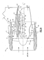
- Figure 1A illustrates a general partial fragmentary schematic view of a gas turbofan engine 10 suspended from an engine pylon P within an engine nacelle assembly N as is typical of an aircraft designed for subsonic operation.
- the turbofan engine 10 includes a core engine within a core nacelle 12 that houses a low spool 14 and high spool 24.
- the low spool 14 includes a low pressure compressor 16 and low pressure turbine 18.
- the low spool 14 drives a fan section 20 through a gear train 22.
- the high spool 24 includes a high pressure compressor 26 and high pressure turbine 28.
- a combustor 30 is arranged between the high pressure compressor 26 and high pressure turbine 28.
- the low and high spools 14, 24 rotate about an engine axis of rotation A.
- the engine 10 is preferably a high-bypass geared turbofan aircraft engine.
- the engine 10 bypass ratio is greater than ten (10:1)
- the turbofan diameter is significantly larger than that of the low pressure compressor 16
- the low pressure turbine 18 has a pressure ratio that is greater than 5:1.
- the gear train 22 is preferably an epicycle gear train such as a planetary gear system or other gear system with a gear reduction ratio of greater than 2.5:1. It should be understood, however, that the above parameters are only exemplary of a preferred geared turbofan engine and that the present invention is likewise applicable to other gas turbine engines including direct drive turbofans.
- the fan section 20 communicates airflow into the core nacelle 12 to power the low pressure compressor 16 and the high pressure compressor 26.
- Core airflow compressed by the low pressure compressor 16 and the high pressure compressor 26 is mixed with the fuel in the combustor 30 and expanded over the high pressure turbine 28 and low pressure turbine 18.
- the turbines 28, 18 are coupled for rotation with, respective, spools 24, 14 to rotationally drive the compressors 26, 16 and through the gear train 22, the fan section 20 in response to the expansion.
- a core engine exhaust E exits the core nacelle 12 through a core nozzle 43 defined between the core nacelle 12 and a tail cone 32.
- the core nacelle 12 is supported within the fan nacelle 34 by structure 36 often generically referred to as an upper and lower bifurcation.
- a bypass flow path 40 is defined between the core nacelle 12 and the fan nacelle 34.
- the engine 10 generates a high bypass flow arrangement with a bypass ratio in which approximately 80 percent of the airflow entering the fan nacelle 34 becomes bypass flow B.
- the bypass flow B communicates through the generally annular bypass flow path 40 and is discharged from the engine 10 through a fan variable area nozzle (FVAN) 42 which defines a nozzle exit area 44 between the fan nacelle 34 and the core nacelle 12 at a fan nacelle end segment 34S of the fan nacelle 34 downstream of the fan section 20.
- FVAN fan variable area nozzle
- Thrust is a function of density, velocity, and area. One or more of these parameters can be manipulated to vary the amount and direction of thrust provided by the bypass flow B.
- the FVAN 42 operates to effectively vary the area of the fan nozzle exit area 44 to selectively adjust the pressure ratio of the bypass flow B in response to a controller C.
- the fan section 20 of the engine 10 is preferably designed for a particular flight condition -- typically cruise at 0.8M and 35,000 feet. As the fan section 20 are efficiently designed at a particular fixed stagger angle for an efficient cruise condition, the FVAN 42 is operated to effectively vary the fan nozzle exit area 44 to adjust fan bypass air flow such that the angle of attack or incidence on the fan blades is maintained close to the design incidence for efficient engine operation at other flight conditions, such as landing and takeoff thus providing optimized engine operation over a range of flight conditions with respect to performance and other operational parameters such as noise levels.
- the FVAN 42 preferably provides an approximately 20% (twenty percent) change in area of the fan exit nozzle area 44.
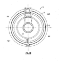
- the FVAN 42 is preferably separated into at least four sectors 42A-42D ( Figure 1B ) which are each independently adjustable to asymmetrically vary the fan nozzle exit area 44 to generate vectored thrust. It should be understood that although four segments are illustrated, any number of segments may alternatively or additionally be provided.
- the FVAN 42 communicates with a controller C or the like to adjust the fan nozzle exit area 44 in a symmetrical and asymmetrical manner.
- Other control systems including an engine controller or aircraft flight control system may also be usable with the present invention.
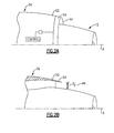
- the FVAN 42 generally includes an axial overlapped nozzle assembly 50 having a first fan nacelle section 52 and a second fan nacelle section 54 movably mounted relative the first fan nacelle section 52.
- the second fan nacelle section 54 axially slides along the engine axis A relative the fixed first fan nacelle section 52 to change the effective area of the fan nozzle exit area 44.
- the second fan nacelle section 54 preferably slides forward toward the fan section 20 upon a longitudinal track 56 (illustrated schematically) in response to an actuator 58.
- the second fan nacelle section 54 preferably defines an annular fan section which moves as a unit.
- the second fan nacelle section 54 may subdivided into a multiple of fan nacelle sectors ( Figures 1B and 4 ) to facilitate thrust vectoring operations through relative movement of the fan nacelle sectors.
- the axial overlapped nozzle assembly 50 changes the physical area and geometry of the bypass flow path 40 during particular flight conditions.
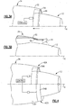
- the bypass flow B is effectively altered by sliding of the second fan nacelle section 54 relative the first fan nacelle section 52 between a closed position ( Figures 2A and 2B ) and an open position ( Figures 3A and 3B ).
- the axial overlapped nozzle assembly 50 is closed by positioning the second fan nacelle section 54 in-line with the first fan nacelle section 52 to define the fan nozzle exit area 44 as exit area F0 ( Figure 2A ).
- the axial overlapped nozzle assembly 50 is opened by moving the second fan nacelle section 54 forward into the first fan nacelle section 52 such that the second fan nacelle section 54 overlaps the first fan nacelle section 52 to provide an increased exit area F1 and F2 defined by the fan nozzle exit area 44 ( Figure 3A ). That is fan nozzle exit area 44 includes exit areas F1 and F2 ( Figure 3B ) which together are greater than exit area F0 ( Figure 2B ).
- the FVAN 42 communicates with the controller C to move the second fan nacelle section 54 relative the first fan nacelle section 52 of the axial overlapped nozzle assembly 50 to effectively vary the area defined by the fan nozzle exit area 44.
- Other control systems including an engine controller or an aircraft flight control system may also be usable with the present invention.
- engine bypass flow is selectively vectored to provide, for example only, trim balance, thrust controlled maneuvering, enhanced ground operations and short field performance.
Landscapes
- Engineering & Computer Science (AREA)
- Chemical & Material Sciences (AREA)
- Combustion & Propulsion (AREA)
- Mechanical Engineering (AREA)
- General Engineering & Computer Science (AREA)
- Structures Of Non-Positive Displacement Pumps (AREA)
- Control Of Turbines (AREA)
Claims (11)
- Gondelanordnung für ein Gasturbinentriebwerk, aufweisend:eine Kerngondel (12), die um eine Achse (A) gebildet ist;eine Bläsergondel (34), die zumindest teilweise um die Kerngondel (12) angebracht ist, um einen Bläserbypass-Strömungsweg (40) zu bilden; undeine Bläserdüse (42) mit variabler Fläche in Verbindung mit dem Bläserbypass-Strömungsweg (40), wobei die Bläserdüse (42) mit variabler Fläche einen ersten Bläsergondelbereich (52) und einen zweiten Bläsergondelbereich (54) aufweist;dadurch gekennzeichnet,dass der zweite Bläsergondelbereich (54) von einer mit dem ersten Bläsergondelbereich (52) ausgerichteten Position zum Bilden einer geschlossenen Position der Bläserdüsenaustrittsfläche (44) axial entlang der Achse (A) nach vorne in den ersten Bläsergondelbereich (52) hinein bewegbar ist, so dass der zweite Bläsergondelbereich (54) den ersten Bläsergondelbereich (52) überlappt, um eine vergrößerte Bläserdüsenaustrittsfläche (44) zu schaffen.
- Anordnung nach Anspruch 1,
wobei der zweite Bläsergondelbereich (54) halbringförmig ist. - Anordnung nach Anspruch 1,
wobei der erste Bläsergondelbereich (52) und der zweite Bläsergondelbereich (54) ringförmig sind. - Anordnung nach Anspruch 1,
wobei der zweite Bläsergondelbereich (54) einen hinteren Rand der Bläserdüse (44) mit variabler Fläche bildet. - Anordnung nach Anspruch 1,
wobei der zweite Bläsergondelbereich (54) in mehrere unabhängig betreibbare Sektoren (54A, 54B) unterteilt ist, wobei jeder der mehreren unabhängig betreibbaren Sektoren (54A, 54B) relativ zu dem ersten Bläsergondelbereich (52) axial bewegbar ist, um eine asymmetrische Bläserdüsenaustrittsfläche (44) zu bilden. - Anordnung nach Anspruch 1,
wobei der zweite Bläsergondelbereich (54) in Reaktion auf eine Nicht-Reiseflugbedingung in die überlappende Position bewegbar ist und in Reaktion auf eine Reiseflugbedingung in die ausgerichtete Position bewegbar ist, in der der zweite Bläsergondelbereich nach und nach mit dem ersten Bläsergondelbereich (52) ausgerichtet wird. - Gasturbinentriebwerk (10), aufweisend:ein Kerntriebwerk, das um eine Achse (A) gebildet ist;ein Getriebesystem (22), das von dem Kerntriebwerk angetrieben wird;einen Turbobläser (20), der von dem Getriebesystem um die Achse (A) angetrieben wird; undeine Gondelanordnung nach einem der vorhergehenden Ansprüche;wobei die Kerngondel (12) zumindest teilweise um das Kerntriebwerk gebildet ist.
- Triebwerk nach Anspruch 7,
weiterhin aufweisend eine Steuerung (C) in Verbindung mit einem Aktuatorsystem, um den zweiten Bläsergondelbereich (54) relativ zu dem ersten Bläsergondelbereich axial die Achse entlang zu bewegen, um die Bläserdüsenaustrittsfläche (44) in Reaktion auf eine Flugbedingung zu variieren. - Verfahren zum Variieren einer Bläserdüsenaustrittsfläche (44) eines Gasturbinentriebwerks (10), wobei das Verfahren folgenden Schritt aufweist:(A) Positionieren eines ersten Bläsergondelbereichs (52) und eines zweiten Bläsergondelbereichs (54) um eine Achse (A); und gekennzeichnet durch einen weiteren Schritt:(B) axiales Bewegen des zweiten Bläsergondelbereichs (54) relativ zu dem ersten Bläsergondelbereich (52) entlang der Achse von einer mit dem ersten Bläsergondelbereich (52) ausgerichteten Position, um eine geschlossene Position der Bläserdüsenaustrittsfläche (44) zu bilden, nach vorne in den ersten Bläsergondelbereich (52) hinein, so dass der zweite Bläsergondelbereich (44) den ersten Bläsergondelbereich (52) überlappt, um in Reaktion auf eine Flugbedingung eine vergrößerte Bläserdüsenaustrittsfläche (44) zu schaffen.
- Verfahren nach Anspruch 9,
wobei der Schritt (B) Folgendes beinhaltet:(a) axiales Bewegen des zweiten Bläsergondelbereichs (54) in den ersten Bläsergondelbereich (52) hinein zumindest in teilweise Überlappung mit dem ersten Bläsergondelbereich (52) um die Achse (A) in Reaktion auf eine Nicht-Reiseflugbedingung. - Verfahren nach Anspruch 9,
wobei der Schritt (B) Folgendes beinhaltet:(a) axiales Bewegen des zweiten Bläsergondelbereichs (54) nach und nach in Ausrichtung mit dem ersten Bläsergondelbereich (52) um die Achse (A) in Reaktion auf eine Reiseflugbedingung.
Applications Claiming Priority (1)
| Application Number | Priority Date | Filing Date | Title |
|---|---|---|---|
| PCT/US2006/039794 WO2008045049A1 (en) | 2006-10-12 | 2006-10-12 | Gas turbine engine with axial movable fan variable area nozzle |
Publications (2)
| Publication Number | Publication Date |
|---|---|
| EP2069630A1 EP2069630A1 (de) | 2009-06-17 |
| EP2069630B1 true EP2069630B1 (de) | 2013-11-20 |
Family
ID=38068586
Family Applications (1)
| Application Number | Title | Priority Date | Filing Date |
|---|---|---|---|
| EP06825793.0A Active EP2069630B1 (de) | 2006-10-12 | 2006-10-12 | Gondelanordnung und zugehöriges Verfahren |
Country Status (3)
| Country | Link |
|---|---|
| US (1) | US20100050595A1 (de) |
| EP (1) | EP2069630B1 (de) |
| WO (1) | WO2008045049A1 (de) |
Families Citing this family (15)
| Publication number | Priority date | Publication date | Assignee | Title |
|---|---|---|---|---|
| US10167813B2 (en) | 2007-08-23 | 2019-01-01 | United Technologies Corporation | Gas turbine engine with fan variable area nozzle to reduce fan instability |
| US9494084B2 (en) | 2007-08-23 | 2016-11-15 | United Technologies Corporation | Gas turbine engine with fan variable area nozzle for low fan pressure ratio |
| US9701415B2 (en) | 2007-08-23 | 2017-07-11 | United Technologies Corporation | Gas turbine engine with axial movable fan variable area nozzle |
| US8973364B2 (en) | 2008-06-26 | 2015-03-10 | United Technologies Corporation | Gas turbine engine with noise attenuating variable area fan nozzle |
| US20110120079A1 (en) * | 2009-11-24 | 2011-05-26 | Schwark Jr Fred W | Variable area fan nozzle stiffeners and placement |
| WO2013126123A1 (en) * | 2011-12-08 | 2013-08-29 | United Technologies Corporation | Gas turbine engine with axial movable fan variable area nozzle |
| EP2798162A4 (de) * | 2011-12-30 | 2015-08-26 | United Technologies Corp | Gasturbinenmotor mit lüfterdüse mit veränderlichem bereich |
| US9394852B2 (en) | 2012-01-31 | 2016-07-19 | United Technologies Corporation | Variable area fan nozzle with wall thickness distribution |
| US8375699B1 (en) | 2012-01-31 | 2013-02-19 | United Technologies Corporation | Variable area fan nozzle with wall thickness distribution |
| US8862362B2 (en) | 2012-07-02 | 2014-10-14 | United Technologies Corporation | Scheduling of variable area fan nozzle to optimize engine performance |
| US9989009B2 (en) | 2012-10-31 | 2018-06-05 | The Boeing Company | Methods and apparatus for sealing variable area fan nozzles of jet engines |
| US20160017815A1 (en) * | 2013-03-12 | 2016-01-21 | United Technologies Corporation | Expanding shell flow control device |
| CA2862597C (en) * | 2013-10-03 | 2018-12-11 | Karl L. Hasel | Geared gas turbine engine architecture for enhanced efficiency |
| US9488130B2 (en) | 2013-10-17 | 2016-11-08 | Honeywell International Inc. | Variable area fan nozzle systems with improved drive couplings |
| US11585294B2 (en) * | 2020-02-21 | 2023-02-21 | Raytheon Technologies Corporation | High bypass ratio engine bypass duct nozzle with controlled nozzle area |
Family Cites Families (10)
| Publication number | Priority date | Publication date | Assignee | Title |
|---|---|---|---|---|
| GB1418905A (en) * | 1972-05-09 | 1975-12-24 | Rolls Royce | Gas turbine engines |
| US3779010A (en) * | 1972-08-17 | 1973-12-18 | Gen Electric | Combined thrust reversing and throat varying mechanism for a gas turbine engine |
| GB1503425A (en) * | 1976-08-04 | 1978-03-08 | Hallowell E | Gas turbine ducted fan jet engines for supersonic flight |
| GB2043786B (en) * | 1979-03-10 | 1983-01-12 | Rolls Royce | Gas turbine engine power plant |
| GB2189550A (en) | 1986-04-25 | 1987-10-28 | Rolls Royce | A gas turbine engine powerplant with flow control devices |
| US5778659A (en) * | 1994-10-20 | 1998-07-14 | United Technologies Corporation | Variable area fan exhaust nozzle having mechanically separate sleeve and thrust reverser actuation systems |
| FR2742482B1 (fr) | 1995-12-19 | 1998-02-06 | Hurel Dubois Avions | Inverseur de poussee a tuyere a section reglable pour moteur d'avion a reaction |
| US5806302A (en) | 1996-09-24 | 1998-09-15 | Rohr, Inc. | Variable fan exhaust area nozzle for aircraft gas turbine engine with thrust reverser |
| US6170254B1 (en) * | 1998-12-18 | 2001-01-09 | Rohr, Inc. | Translating sleeve for cascade type thrust reversing system for fan gas turbine engine for an aircraft |
| US7340883B2 (en) * | 2004-11-12 | 2008-03-11 | The Boeing Company | Morphing structure |
-
2006
- 2006-10-12 US US12/373,575 patent/US20100050595A1/en not_active Abandoned
- 2006-10-12 EP EP06825793.0A patent/EP2069630B1/de active Active
- 2006-10-12 WO PCT/US2006/039794 patent/WO2008045049A1/en not_active Ceased
Also Published As
| Publication number | Publication date |
|---|---|
| US20100050595A1 (en) | 2010-03-04 |
| WO2008045049A1 (en) | 2008-04-17 |
| EP2069630A1 (de) | 2009-06-17 |
Similar Documents
| Publication | Publication Date | Title |
|---|---|---|
| US9822732B2 (en) | Gas turbine engine with axial movable fan variable area nozzle | |
| US8074440B2 (en) | Gas turbine engine with axial movable fan variable area nozzle | |
| US10047628B2 (en) | Gas turbine engine with fan variable area nozzle for low fan pressure ratio | |
| US8662417B2 (en) | Gas turbine engine fan variable area nozzle with swivable insert system | |
| EP2420665B2 (de) | Variable Bereichsventilatordüse | |
| EP2798188A1 (de) | Gasturbinenmotor mit lüfterdüse mit veränderlichem bereich für niedriges lüfterdruckverhältnis | |
| EP2069630B1 (de) | Gondelanordnung und zugehöriges Verfahren | |
| US20130149112A1 (en) | Gas turbine engine with fan variable area nozzle | |
| EP2074319B1 (de) | Turbinentriebwerk mit gebläsedüse mit variablem austrittquerschnitt, gondelanordnung für solch ein triebwerk und entsprechendes betriebsverfahren | |
| US20130149111A1 (en) | Gas turbine engine with fan variable area nozzle for low fan pressure ratio | |
| US10167813B2 (en) | Gas turbine engine with fan variable area nozzle to reduce fan instability | |
| EP2115289B1 (de) | Gasturbinentriebwerk mit variabler bläser düse mit überlappenden drehbaren segmenten | |
| WO2013126123A1 (en) | Gas turbine engine with axial movable fan variable area nozzle | |
| EP2798184A1 (de) | Gasturbinenmotor mit lüfterdüse mit veränderlichem bereich für niedriges lüfterdruckverhältnis | |
| EP2798162A2 (de) | Gasturbinenmotor mit lüfterdüse mit veränderlichem bereich | |
| EP2798187A1 (de) | Gasturbinenmotor mit lüfterdüse mit veränderlichem bereich zur reduzierung der lüfterinstabilität |
Legal Events
| Date | Code | Title | Description |
|---|---|---|---|
| PUAI | Public reference made under article 153(3) epc to a published international application that has entered the european phase |
Free format text: ORIGINAL CODE: 0009012 |
|
| 17P | Request for examination filed |
Effective date: 20090330 |
|
| AK | Designated contracting states |
Kind code of ref document: A1 Designated state(s): DE GB |
|
| AX | Request for extension of the european patent |
Extension state: AL BA HR MK RS |
|
| RBV | Designated contracting states (corrected) |
Designated state(s): DE GB |
|
| DAX | Request for extension of the european patent (deleted) | ||
| RBV | Designated contracting states (corrected) |
Designated state(s): DE GB |
|
| 17Q | First examination report despatched |
Effective date: 20120126 |
|
| GRAP | Despatch of communication of intention to grant a patent |
Free format text: ORIGINAL CODE: EPIDOSNIGR1 |
|
| INTG | Intention to grant announced |
Effective date: 20130521 |
|
| GRAS | Grant fee paid |
Free format text: ORIGINAL CODE: EPIDOSNIGR3 |
|
| GRAA | (expected) grant |
Free format text: ORIGINAL CODE: 0009210 |
|
| AK | Designated contracting states |
Kind code of ref document: B1 Designated state(s): DE GB |
|
| REG | Reference to a national code |
Ref country code: GB Ref legal event code: FG4D |
|
| REG | Reference to a national code |
Ref country code: DE Ref legal event code: R096 Ref document number: 602006039374 Country of ref document: DE Effective date: 20140116 |
|
| REG | Reference to a national code |
Ref country code: DE Ref legal event code: R097 Ref document number: 602006039374 Country of ref document: DE |
|
| PLBE | No opposition filed within time limit |
Free format text: ORIGINAL CODE: 0009261 |
|
| STAA | Information on the status of an ep patent application or granted ep patent |
Free format text: STATUS: NO OPPOSITION FILED WITHIN TIME LIMIT |
|
| 26N | No opposition filed |
Effective date: 20140821 |
|
| REG | Reference to a national code |
Ref country code: DE Ref legal event code: R097 Ref document number: 602006039374 Country of ref document: DE Effective date: 20140821 |
|
| REG | Reference to a national code |
Ref country code: DE Ref legal event code: R082 Ref document number: 602006039374 Country of ref document: DE Representative=s name: SCHMITT-NILSON SCHRAUD WAIBEL WOHLFROM PATENTA, DE |
|
| REG | Reference to a national code |
Ref country code: DE Ref legal event code: R082 Ref document number: 602006039374 Country of ref document: DE Representative=s name: SCHMITT-NILSON SCHRAUD WAIBEL WOHLFROM PATENTA, DE Ref country code: DE Ref legal event code: R081 Ref document number: 602006039374 Country of ref document: DE Owner name: UNITED TECHNOLOGIES CORP. (N.D.GES.D. STAATES , US Free format text: FORMER OWNER: UNITED TECHNOLOGIES CORP., HARTFORD, CONN., US |
|
| PGFP | Annual fee paid to national office [announced via postgrant information from national office to epo] |
Ref country code: DE Payment date: 20200917 Year of fee payment: 15 |
|
| REG | Reference to a national code |
Ref country code: DE Ref legal event code: R119 Ref document number: 602006039374 Country of ref document: DE |
|
| PG25 | Lapsed in a contracting state [announced via postgrant information from national office to epo] |
Ref country code: DE Free format text: LAPSE BECAUSE OF NON-PAYMENT OF DUE FEES Effective date: 20220503 |
|
| PGFP | Annual fee paid to national office [announced via postgrant information from national office to epo] |
Ref country code: GB Payment date: 20250923 Year of fee payment: 20 |