EP2068453B1 - Détection de chemin de signification principal - Google Patents
Détection de chemin de signification principal Download PDFInfo
- Publication number
- EP2068453B1 EP2068453B1 EP20080020956 EP08020956A EP2068453B1 EP 2068453 B1 EP2068453 B1 EP 2068453B1 EP 20080020956 EP20080020956 EP 20080020956 EP 08020956 A EP08020956 A EP 08020956A EP 2068453 B1 EP2068453 B1 EP 2068453B1
- Authority
- EP
- European Patent Office
- Prior art keywords
- signal path
- data
- energy
- time
- delay
- Prior art date
- Legal status (The legal status is an assumption and is not a legal conclusion. Google has not performed a legal analysis and makes no representation as to the accuracy of the status listed.)
- Not-in-force
Links
Images


Classifications
-
- H—ELECTRICITY
- H04—ELECTRIC COMMUNICATION TECHNIQUE
- H04B—TRANSMISSION
- H04B1/00—Details of transmission systems, not covered by a single one of groups H04B3/00 - H04B13/00; Details of transmission systems not characterised by the medium used for transmission
- H04B1/69—Spread spectrum techniques
- H04B1/707—Spread spectrum techniques using direct sequence modulation
- H04B1/7097—Interference-related aspects
- H04B1/711—Interference-related aspects the interference being multi-path interference
- H04B1/7115—Constructive combining of multi-path signals, i.e. RAKE receivers
- H04B1/7117—Selection, re-selection, allocation or re-allocation of paths to fingers, e.g. timing offset control of allocated fingers
Definitions
- the invention relates to a method and apparatus for processing a received multipath signal, in particular for determining the earliest significant signal path.
- the invention has application in, for example but not exclusively, the Universal Mobile Telecommunication System (UMTS) and in particular the High Speed Downlink Packet Access (HSDPA) service of UMTS.
- UMTS Universal Mobile Telecommunication System
- HSDPA High Speed Downlink Packet Access
- the HSDPA scheme has been introduced in Release-5 of the UMTS standard to provide a high data rate service.
- a suitable receiver architecture is considered to be the well known Rake receiver.
- a Rake receiver is considered less suitable and a receiver employing an equaliser is considered preferable.
- the equaliser needs information about the earliest significant signal path, referred to in the present specification and claims as the first significant path (FSP), of a received multipath signal. This is in contrast to a Rake receiver which employs the timing of all the paths.
- the present invention addresses the provision of information about the FSP.
- a suitable equaliser is a variant of the Normalised Least Means Squares (NLMS) equaliser, implemented as an adaptive finite impulse response (FIR) filter and which requires the FSP to be placed near the centre of the equaliser window.
- NLMS Normalised Least Means Squares
- FIR adaptive finite impulse response
- An object of the invention is to provide a way of determining the FSP of a received multipath signal.
- WO 2004/107697 A discloses discloses a method of detecting multipath components in a time-varying fading radio channel.
- the method comprises generating an averaged delay profile from a number of repetitively calculated instantaneous delay profiles of multipath components, and estimating from the averaged delay profile the delay of each individual multipath component.
- the generation of the averaged delay profile is limited to comprise only delay values in a subset of the range of possible delay values.
- US 2007/041431 A1 discloses a method of detecting multipath components in a time-varying fading radio channel.
- the delays of individual multipath components is estimated and a delay profile calculated repetitively.
- the method comprises searching repetitively for new multipath components in a search window constituting a subset of the possible delays.
- the position of the search window is selected based on the sum of power of the multipath components in the search window.
- a received multipath signal comprising a plurality of signal paths to determine the earliest significant signal path, the method comprising:
- the data may in step b) be filtered to spread the energy of the signal paths in time.
- a persistence test can be performed to identify signal paths which are present in a plurality of time periods, thereby enabling noise and spurious signals to be ignored.
- the energy of the identified signal paths can be combined and in step e) a test applied to the combined energy in order to determine the time of the FSP. In this way, the invention provides an efficient and robust algorithm for determining the FSP.
- an apparatus for processing a received multipath signal comprising a plurality of signal paths to determine the earliest significant signal path, the apparatus comprising:
- the invention also extends to apparatus according to the second aspect of the invention adapted for carrying out the method according to the first aspect of the invention.
- This might comprise a processor, digital signal processor (DSP), central processing unit (CPU) or such like. Additionally or alternatively, it might comprise a hard-wired circuit or circuits, such as an application-specific integrated circuit (ASIC), or embedded software.
- DSP digital signal processor
- CPU central processing unit
- ASIC application-specific integrated circuit
- embedded software such as an application-specific integrated circuit (ASIC), or embedded software.
- the invention also extends to a mobile station comprising the apparatus, and to a mobile communication system comprising a transmitter for transmitting signals and a mobile station comprising the apparatus for processing the transmitted signals when received as multipath signals.
- the invention also extends to computer software or computer program code adapted to carry out the method according to the first aspect of the invention when processed by a processing means.
- a computer readable medium comprising a computer program adapted to perform the method according to the first aspect of the invention.
- the medium may be a physical storage medium such as a Read Only Memory (ROM) chip.
- ROM Read Only Memory
- it may be a disk such as a Digital Versatile Disk (DVD-ROM) or Compact Disk (CD-ROM).
- DVD-ROM Digital Versatile Disk
- CD-ROM Compact Disk
- It could also be a signal such as an electronic signal over wires, an optical signal or a radio signal such as to a satellite or the like.
- the invention also extends to a processor running the software or code, e.g. a computer configured to carry out the method according to the first aspect of the invention.
- the data representative of energy may be normalised prior to the filtering. This can reduce the effect of variations in receiver gain in the different time periods, such as may be caused by automatic gain control (AGC) circuitry.
- AGC automatic gain control
- the apparatus according to the second aspect of the invention may comprise normalisation means coupled to the data input means and adapted to normalise the data representative of energy prior to the filtering, to reduce the effect of variations in receiver gain in the different time periods.
- the data may be sampled data derived at sample intervals, and the filtering may spread the data for each signal path over a range of one of 3, 4 or 5 sample intervals.
- the data may be sampled data derived at sample intervals, and the data filtering means may be adapted to spread each signal path over a range of one of 3, 4 or 5 sample intervals. Such a range of values enables noise and spurious signals to be differentiated reliably from valid signals.
- the filtering may be performed with a symmetric finite impulse response (FIR) filter, for example having three taps, and in the apparatus the data filtering means may comprise a symmetric finite impulse response filter.
- FIR symmetric finite impulse response
- Such a filter is simple to implement and can provide a better performance than a non-symmetric filter.
- the plurality of time periods in step c) may comprise one of 2, 3, or 4 time periods, and in the apparatus the plurality of time periods employed by the signal path identification means may comprise one of 2, 3 or 4 time periods.
- Such a range of values enables noise and spurious signals to be differentiated reliably.
- step d) may comprise determining the indication of combined energy within successive positions of a sliding window of duration shorter than the time period, and in the apparatus the energy determination means may be adapted to determine the indication of combined energy within successive positions of a sliding window of duration shorter than the time period.
- the predetermined criterion of step e) may comprise maximisation of the combined energy within the sliding window
- selecting the earliest significant signal path dependent on the determined time may comprise selecting the signal path which has its peak data value at the delay where the combined energy within the sliding window is maximised.
- the predetermined criterion employed by the energy assessment means may comprise maximisation of the combined energy within the sliding window.
- the path selection means may be adapted to select the earliest significant signal path by selecting the signal path which has its peak data value at the delay where the combined energy within the sliding window is maximised.
- the data may be sampled data derived at sample intervals, and the length of the window may be 8 sample intervals.
- the indication of combined energy may comprise an indication of cumulative energy through the time period
- the energy determination means may be adapted to determine the indication of combined energy as an indication of cumulative energy through the time period.
- the indication of cumulative energy may be a cumulative density function.
- the predetermined criterion of step e) may comprise reaching a threshold value
- selecting the earliest significant signal path may comprise selecting the earliest signal path that has its peak data value at or after the determined time.
- the predetermined criterion employed by the criterion assessment means may comprise reaching a threshold value.
- the path selection means may be adapted to select the earliest significant signal path dependent on the determined time by selecting the earliest signal path that has its peak data value at or after the determined time.
- the relative delay of the selected earliest significant signal path may be employed in an equaliser for further processing the received multipath signal, and the apparatus may comprise equalisation means adapted to employ the relative delay of the selected earliest significant signal path for further processing the received multipath signal, thereby enabling effective channel estimation by alignment of the FSP with the equaliser window.
- the relative delay of the selected earliest significant signal path may also be employed for generating data representative of the energy and relative delay of received signal paths, and the apparatus may comprise data generation means adapted to employ the relative delay of the selected earliest significant signal path for generating data representative of the energy and relative delay of received signal paths, thereby enabling performance to be progressively improved by iteration of the method.
- the relative delay of the selected earliest significant signal path may be adjusted by a bias value dependent on the delay spread of the signal paths, before being employed in an equaliser, and the apparatus may comprise equalisation means-adapted to employ the relative delay of the selected earliest significant signal path, adjusted by a bias value dependent on the delay spread of the signal paths, for further processing the received multipath signal. This enables the energy in the equaliser window to be increased in cases where the extent of delay spread would otherwise cause signal paths to fall outside of the equaliser window.
- an indication of the delay spread of the signal paths may be determined as an indication of the time between the occurrences of two values of the cumulative energy
- the apparatus may comprise delay spread determination means adapted to determine an indication of the delay spread of the signal paths as an indication of the time between the occurrence of two values of the cumulative energy.
- the relative delay of the selected earliest significant signal path, adjusted by a bias value dependent on the delay spread of the signal paths, may be employed for generating data representative of the amplitude and relative delay of received signal paths
- the apparatus may comprise data generation means adapted to employ the relative delay of the selected earliest significant signal path, adjusted by a bias value dependent on the delay spread of the signal paths, for generating data representative of the amplitude and relative delay of received signal paths, thereby enabling performance to be progressively improved by iteration.
- the relative delay of the selected earliest significant signal path may be employed only if that delay differs from a previously determined relative delay of a previously selected earliest significant signal path by more than a predetermined hysteresis value, otherwise the previously determined relative delay may be employed, and the apparatus may be adapted to employ the relative delay of the selected earliest significant signal path only if that time differs from a previously determined relative delay of a previously selected earliest significant signal path by more than a predetermined hysteresis value, otherwise employing the previously determined relative time of receipt.
- This provides hysteresis which can reduce the effect of jitter in the time of receipt of the selected earliest significant signal path.
- the relative delay of the selected earliest significant signal path may be employed only if that delay differs from a previously determined relative delay of a previously selected earliest significant signal path by less than a predetermined slew value, otherwise the previously determined relative delay may be employed adjusted by the predetermined slew value, and the apparatus may be adapted to employ the relative delay of the selected earliest significant signal path only if that time differs from a previously determined relative delay of a previously selected earliest significant signal path by less than a predetermined slew value, otherwise employing the previously determined relative delay adjusted by the predetermined slew value.
- This in effect limits the maximum change in delay employed to the predetermined slew value, which can prevent the undesirable effect of larger time changes.
- the multipath signal may be a CDMA signal, and the apparatus may be adapted to process a received multipath CDMA signal.
- the CDMA signal may comprise chips, the sample interval may be half of the chip duration, and the apparatus may be adapted to sample the CDMA signal at intervals of half a chip duration.
- the apparatus may be adapted to perform any of the methods described.
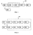
- the mobile station 100 comprises a receiver 120 coupled to an antenna for receiving a signal from the base station 200.
- This signal is a multipath signal, comprising a plurality of signal components each received via a different signal path due to reflections.
- the receiver 120 is adapted to receive radio frequency signals, convert the radio frequency signals to baseband or to a low intermediate frequency, and to apply channel filtering to reject unwanted signals occurring at other frequencies.
- the resulting signal is delivered on an output of the receiver 120 which is coupled to an input of a searcher 130 which processes the signal to provide in each of a series of time periods data representative of the energy and relative delay of the signal components received by different paths.
- a searcher 130 which processes the signal to provide in each of a series of time periods data representative of the energy and relative delay of the signal components received by different paths.
- signal component and, more frequently, “signal path” are used to mean a signal received via a particular path.
- data representative of energy is also representative of amplitude.
- This data is provided at an output of the searcher 130 which is coupled to an input of a processing stage 140 which determines the time of the FSP as described below.
- the time of the FSP is provided at an output of the processing stage 140 which is coupled to an input of an equaliser 150.
- the equaliser 150 is also coupled to an output of the receiver 120, and the equaliser 150 employs the indicated time of the FSP to perform equalisation of the signal delivered by the receiver 120.
- An output of the equaliser 150 is coupled to further stages 160 of the mobile station 100 for demodulating and decoding the signal, the details of which will not be described as they are not pertinent to the understanding of the present invention.
- the output of the processing stage 140 is also optionally coupled to an input of the searcher 130 in which case the time of the FSP indicated by the processing stage 140 can be employed by the searcher 130 to provide a timing reference for subsequent determinations of the FSP.
- FIG 2 illustrates a method of processing a received multipath signal as implemented by the processing stage 140.
- the method commences at step 205 with the provision for each of a series of time periods of data representative of the energy and relative delay of signal components received by different paths. This corresponds to the data provided at the output of the searcher 130 in Figure 1 .
- each time period may correspond to a frame which has a duration of 10ms.
- the data may be sampled data corresponding to a sample rate of twice the UMTS chip rate of 3.84 Mchip.s -1 .
- the data is optionally normalised, which can reduce the effect of variations in receiver gain in the different time periods, such as may be caused by automatic gain control (AGC) circuitry in the receiver 120.
- AGC automatic gain control
- the data for each time period is filtered to spread in time the data corresponding to each signal path.
- the filtering may be performed by a symmetric FIR filter.
- a suitable symmetric FIR filter would have three taps, thereby spreading the data over three sample periods.
- a persistence test is performed by identifying from the filtered data a signal path which appears at the same relative delay in a plurality of the time periods, and identifying any further such signal paths.
- the plurality of time periods may preferably comprise one of 2, 3, or 4 time periods.
- an indication of the combined energy of the filtered data of the identified signal paths is determined.
- a time at which the indication from step 225 satisfies a predetermined criterion is determined, and at step 235 the FSP is selected dependent on the determined time.
- the combined energy determined at step 225 may be calculated within successive positions of a sliding window having a duration less than the time period, and the predetermined criterion applied in step 230 may comprise maximisation of the combined energy within the sliding window.
- the signal path which has its peak data value at the delay where the combined energy within the sliding window is maximised may be selected at step 235 as the FSP.
- Such a sliding window may preferably have a length of 8 or 16 sample intervals.
- the combined energy determined at step 225 may be calculated as the cumulative energy through the time period, and for example may be a cumulative density function (CDF).
- the predetermined criterion applied in step 230 may comprise reaching a threshold value, such as 10%, and selecting the FSP at step 235 may comprise selecting the earliest signal path that has its peak value at or after the determined time.
- hysteresis is optionally applied by using the relative time of the selected FSP only if that time differs from a previously determined relative time of a previously selected FSP by more than a predetermined hysteresis value, and otherwise using the previously determined relative time of receipt. In this way small, frequent changes in time of the FSP can be ignored, thereby reducing jitter.
- a slew rate test is optionally applied by using the relative time of receipt of the selected FSP only if that time differs from a previously determined relative time of receipt of a previously selected FSP by less than a predetermined slew value, and otherwise employing the previously determined relative time of receipt adjusted by the predetermined slew value. In this way, in effect, the maximum change in time of the FSP can be limited.
- the relative time of receipt of the selected FSP is employed for further processing.
- time is employed by the equaliser 150 for further processing the received multipath signal; for example the FSP may be aligned around the centre of the equaliser window, which for UMTS may have a width of 15 chip periods (30 sample periods for two times oversampiing).
- time is employed for generating data representative of the energy and relative delay of signal paths.
- the time may be employed by the searcher 130 for generating the data of step 205 for a subsequent iteration of the method steps 210 to 250.
- the time may be adjusted by a bias value dependent on the delay spread of the signal path.
- An indication of the delay spread may be determined as an indication of the time between the occurrence of two values of the cumulative energy. For example the width of the CDF between 10% and 90%, or other values, may be used as indicative of the spread of the channel.
- the width of the CDF is less than 8 chip periods, then the time of receipt of the FSP may remain unadjusted; if the width of the CDF is in the range 8 to 10 chip periods, then the time of receipt of the FSP may be adjusted by a bias value of 2 chip periods to place the FSP earlier in the equaliser window; if the width of the CDF is greater than 10 chip periods, it can be best to place the FSP in the centre of the equaliser window.
- Figure 3 is a block schematic diagram of an apparatus for implementing the method of Figure 2 .
- Searcher 130 is adapted to provide the data in accordance with step 205 and is identical to the searcher 130 illustrated in Figure 1 .
- Stages 310 to 345 in Figure 3 correspond to the processing stage 140 in Figure 1 .
- a normalisation stage 310 is coupled to an output of the searcher 130 and is adapted to perform optional normalisation of the data in accordance with step 210.
- a filter 315 is coupled to an output of the normalisation stage 310 and is adapted to filter the data in accordance with step 215.
- a signal path identification stage 320 is coupled to an output of the filter 315 and is adapted to perform a persistence test in accordance with step 220.
- An energy determination stage 325 is coupled to an output of the signal path identification stage 320 and is adapted to determine an indication of energy in accordance with step 225.
- An energy assessment stage 330 is coupled to an output of the energy determination stage 325 and is adapted to apply the predetermined criterion in accordance with step 230.
- a signal path selection stage 335 is coupled to an output of the energy assessment stage 330 and is adapted to select the FSP in accordance with step 235.
- a hysteresis stage 340 is coupled to an output of the signal path selection stage 335 and is adapted to apply optional hysteresis in accordance with step 240.
- a slew rate stage 345 is coupled to an output of the hysteresis stage 340 and is adapted to perform the optional slew rate test in accordance with step 245.
- Further processing stage 350 is coupled to an output of the slew rate stage 345 and is adapted to perform further processing in accordance with step 250.
- the further processing stage 350 may comprise the equaliser 150 illustrated in Figure 1 .
- an output of the slew rate stage 345 may optionally be coupled to an input of the searcher 130.
- each time period may be a frame, which has a duration of 10ms.
- Each frame comprises 15 slots each comprising 10 symbols, and each symbol comprises 256 chips, with each chip having a duration 0.26 ⁇ s. Therefore each frame comprises 38400 chips, and if the receiver 120 employs an oversampling rate of 2, with each sample corresponding to a half-chip, each frame corresponds to 76800 samples.
- the sample interval is 0.13 ⁇ s.
- the data provided at step 205 may be provided as a first vector of dimension 16 containing the data values, 'pathValues', of up to 16 signal paths, and a second vector of dimension 16 containing the timing, 'pathDelay', of the signal paths relative to an absolute timing reference.
- the data should also include an indication of the absolute timing reference, and may indicate a threshold, 'Thold', which is indicative of the noise level in the receiver 120 and the gain of the receiver 120.
- the absolute timing reference is the reference used to set the offset of a locally generated scrambling code which is correlated with the received signal in order to detect the CPICH.
- the absolute timing reference has a value in the range 0 to 76800 samples, for a sample rate of twice the chip rate.
- the absolute timing reference is set according to the output of the UMTS Primary Synchronisation Channel (PSCH) procedure-and Synchronisation Channel (SCH ) procedure.
- PSCH Primary Synchronisation Channel
- SCH Synchronisation Channel
- the absolute timing reference may be updated for the next frame according to the outcome of the FSP detected as described herein, and as represented by the coupling in Figures 1 and 3 of the output of the further processing stage 140 to an input of the searcher 130.
- the absolute timing reference is an important limitation for the path tracking since the path detection algorithm conventionally used by the searcher 130 can only detect paths that are in the range -8 to +151 samples relative to the absolute reference, i.e. the second vector of dimension 16 containing the timing of the paths, 'pathDelay', will contain values in the range -8 to +151. Therefore, when the absolute timing reference is updated for the next frame according to the outcome of the FSP, it should be offset by -72 samples compared with the computed FSP in order to place the computed FSP in centre of the path detection range.
- the normalisation at step 210 may be performed by dividing the input vector 'pathValues' by the threshold Thold in order to have a measure of the SNR independent of the AGC gain.
- path_Values i P + N ⁇ G AGC where P is the measured power of signal path i, N is the noise power for the current frame, and G AGC is the gain of the receiver 120 for the current frame
- Thold N ⁇ ⁇ G AGC where N ⁇ is the average noise power
- the normalised values are path_Values i Thold ⁇ P N + 1 ⁇ SNR + 1 where SNR is the signal to noise ratio PIN.
- the pathValues information provided in the first vector and the pathDelay information provided in the second vector may be combined by mapping the pathValues to a vector of 160 values where each path is located in the vector according to its respective pathDelay.
- Other numbers of taps may be used, for example 4 or 5.
- An example of the persistence test of step 220 is as follows.
- the data provided by the searcher 130 resulting from the measurements made in one frame is stored for a number of subsequent frame periods, for example 2, 3, 4, or 5 frame periods.
- a test is made to determine, after the application of the filtering, whether the path occurs in the same relative time within the stored previous frames. If such re-occurrence is found, the path is considered persistent and the average value of that path within the frames is stored in a vector path_detected [k] where k is the current position, otherwise the value of the path is not stored.
- diagrams a), b) and c) each represent a frame subdivided into sample periods, with a) and b) representing the n th frame and c) representing the (n-1) th frame.
- Diagram a) illustrates that the searcher 130 has detected the peak of a signal path in the k th sample period of the nth frame.
- Diagram b) illustrates the effect of filtering in a three-tap FIR filter, whereby the energy of the peak is spread over sample periods k, k+1 and k+2. If the persistence test is performed over two frames, persistence will be detected if a peak is detected in the corresponding positions k, k+1 and k+2 of the preceding frame. Due to spreading by the filter 315, this will occur if the searcher 130 has detected a peak in any one of the positions k-2, k-1, k, k+1 and k+2 of the preceding frame.
- Diagram c) of Figure 4 illustrates these five positions in which a signal path peak in the (n-1) th frame prior to filtering will result in the signal path in the k th sample period of the n th frame, prior to filtering, being considered persistent.
- the probability of the searcher 130 detecting a false peak is p n
- the probability of detecting a false peak after the persistence test is equal to the probability that the searcher 130 detects a false peak in one of the five positions around the false peak detected in the previous frame.
- the probability of locking to a false peak after the persistence test is 5p n 2 , which demonstrates that for typical values of p n the persistence test can reduce the likelihood of detecting false signal paths.
- the combined energy of filtered data of the signal paths that satisfy the persistence test may be determined by calculating the energy of these signal paths. Two different ways are described below for,calculating and assessing the combined energy.
- the combined energy is calculated within a sliding window which has a duration shorter than a frame, and may be shorter than the span of the window used by the equaliser 150 which subsequently employs the FSP.
- the channel estimation is used in order to train the equaliser 150.
- the estimated channel impulse response is time reversed and copied into the first half of the equaliser window where the FSP is put into the mid-position.
- the combined energy may be calculated within a sliding window of duration 16 samples.
- a sliding window of 16 samples is selected because, when the FSP is placed in the centre of the CHEST window, signal paths occurring later than 16 samples after the FSP lie outside of the CHEST window and therefore do not contribute to the operation of the equaliser.
- the position FSP_pos of the FSP within the frame is selected as the value of the index i for which E_FSP[i] is maximised.
- Figure 5 shows an example of determining the FSP position in this way.
- the circled points represent peak values of individual signal paths after the filtering.
- the points indicated by squares represent the combined energy E_FSP[i] within a sliding window spanning 16 samples..
- the position of the window which maximises E_FSP[i] is indicated, and also the position FSP_pos.
- the combined energy is calculated as the cumulative energy over the whole duration of the frame, and FSP_pos is determined as the first position within the frame for which the cumulative energy exceeds a threshold.
- the threshold is set at a value of 0.175 and FSP_pos is considered to occur at a delay of 4 samples.
- the delay spread of the channel is taken into account This can be advantageous in situations where the channel delay spread is so large that simply placing the FSP in the centre of the CHEST window results in a large portion of energy lying outside of the CHEST window. This happens, for example, in scenarios where there are two principle signal paths spaced by more than 7 chips (14 samples) and the CHEST window is 30 samples wide. In this case FSP_pos may be biased to increase the energy within the CHEST window.
- the spread of the channel is estimated as the delay difference between the positions within the frame at which the calculated cumulative energy of the energy of the signal paths within the frame exceeds an initial threshold (th_beg in Figure 6 ) at time pos_beg and a final threshold (th_end in Figure 6 ) at time pos_end.
- the spread of the channel is between 8 and 10 chips is a positive bias applied to ensure 100% of the energy of the signal paths of the frame lies within the CHEST window.
- the application of the bias is restricted to the case of a spread of 8 to 10 chips because some of the energy of the FSP can be lost if a squelching mask is used and if FSP_pos is set in the last position before the squelch mask.
- the ideal position for the FSP in the window of the equaliser 150 is the position 16, i.e. 8 chips with the oversampling equal to 2.
- the algorithm is as follows.
- Figure 7 shows the CHEST window and an FSP with two smaller signal paths.
- the top diagram illustrates the ideal position of the FSP in the centre of the CHEST window and the squelch mask at the end.
- the middle diagram illustrates the FSP after a positive bias has been applied, and the lower diagram illustrates the FSP after a negative bias has been applied.
- One advantage of employing this second way is that energy falling within the side lobes of the root raised cosine (RRC) filter typically used in the searcher 130 need not have a significant impact on the FSP selection.
- the searcher 130 especially in case of low noise power, detects the main peak and a peak corresponding to the side lobes of the RRC filter. The side lobes are around -13dB with respect to the main peak. If the FSP is selected where the cumulative energy is higher than, say, 10% of the total energy in the frame, the side lobe energy is an insignificant part of that energy and in effect is not detected.
- the slew rate test of step 245 may be applied as follows to prevent large changes in FSP_pos. If the magnitude of the difference between FSP_pos[n] and FSP_pos[n-1] is larger than a predetermined slew value, then the difference is saturated to the predetermined slew value, i.e. FSP_pos[n] is set equal to FSP_pos[n-1] plus or minus the predetermined slew value, according to whether the difference is positive or negative.
- a constant bias of +/-1 chip from the true FSP location can be tolerated with a performance loss of less than 0.2 dB. It has been found that the performance with an error bias of +1 and +2 chips in certain cases is better than the performance with no error at all. Placing the FSP in the centre of the CHEST window is an approximation of the best placement It has been found that the best placement is such that the constrained MMSE (minimum means square error) solution to the channel estimation is the one with the largest FSP energy in the CHEST window. Due to the squelching mask in the channel estimation process, a positive error has a different effect than a negative error. In particular an error of +3 chips is worse than an error of -3 chips. As the advantage of the squelching mask is uncertain, it is preferable to not use a squelching mask.
- a Gaussian jitter with a standard deviation of up to 0.9 chips with an update rate equal to 10 frames can be tolerated, providing a performance loss with respect to ideal FSP reporting of less than 0.2 dB. The loss will be smaller if the update period is longer or if the errors are correlated.
- a standard deviation of 0.9 in the chip jitter implies that the reported FSP is within +/-1 chip approximately 92% of the lime when quantised to half a chip period.
- the FSP update rate should be faster than 10 frames to ensure the throughput degradation is less than 0.5dB.
- the throughput performance degrades monotonically with increasing update period.
- the lower the update period the better the tracking of the true FSP, and thus the better the throughput performance.
- the standard deviation is greater than zero
- the performance for various update periods does not vary monotonically. In other words, there exists an update period which gives optimum performance in the presence of FSP estimation errors. The reason for such behaviour is as follows.
Landscapes
- Engineering & Computer Science (AREA)
- Computer Networks & Wireless Communication (AREA)
- Signal Processing (AREA)
- Mobile Radio Communication Systems (AREA)
- Noise Elimination (AREA)
Claims (21)
- Procédé de traitement d'un signal à trajets multiples reçu comprenant une pluralité de trajets de signal pour déterminer le trajet de signal significatif le plus précoce, le procédé comprenant les étapes consistant à :a) fournir pour chacune d'une série de périodes des données représentant l'énergie et le retard relatif des trajets de signal et une indication d'une référence de synchronisation absolue ;b) filtrer les données pour chaque période pour répartir les données de chaque trajet de signal ;c) identifier à partir des données filtrées un trajet de signal qui, après la répartition, est présent au même retard dans une pluralité des périodes, et identifier tout tel trajet de signal supplémentaire ;d) déterminer une indication de l'énergie combinée des données filtrées des trajets de signal identifiés dans une période ;e) déterminer un moment auquel l'indication satisfait un critère prédéterminé ;f) sélectionner le trajet de signal significatif le plus précoce en fonction du moment déterminé.
- Procédé selon la revendication 1, comprenant l'étape consistant à normaliser les données représentant l'énergie avant le filtrage afin de réduire l'effet des variations dans un gain de récepteur dans les différentes périodes.
- Procédé selon l'une quelconque des revendications précédentes, dans lequel les données sont des données échantillonnées dérivées à des intervalles d'échantillon, et dans lequel le filtrage répartit chaque trajet de signal sur une plage de l'un de 3, 4 ou 5 intervalles d'échantillon.
- Procédé selon l'une quelconque des revendications précédentes, dans lequel le filtrage emploie un filtre à réponse impulsionnelle finie symétrique (315).
- Procédé selon l'une quelconque des revendications précédentes, dans lequel la pluralité de périodes dans l'étape c) comprend l'une de 2, 3 ou 4 périodes.
- Procédé selon l'une quelconque des revendications précédentes, dans lequel l'étape d) comprend la détermination de l'indication d'énergie combinée dans des positions successives d'une fenêtre coulissante de durée inférieure à la période.
- Procédé selon la revendication 6, dans lequel le critère prédéterminé de l'étape e) comprend la maximisation de l'énergie combinée dans la fenêtre coulissante.
- Procédé selon la revendication 7, dans lequel l'étape consistant à sélectionner le trajet de signal significatif le plus précoce en fonction du moment déterminé comprend la sélection du trajet de signal qui a sa valeur de données de crête au retard où l'énergie combinée dans la fenêtre coulissante est maximisée.
- Procédé selon l'une quelconque des revendications 1 à 5, dans lequel dans l'étape d), l'indication d'énergie combinée comprend une indication d'énergie cumulative à travers la période.
- Procédé selon la revendication 9, dans lequel le critère prédéterminé de l'étape e) comprend la sous-étape consistant à atteindre une valeur seuil.
- Procédé selon la revendication 10, dans lequel l'étape consistant à sélectionner le trajet de signal significatif le plus précoce comprend la sélection du trajet de signal le plus précoce qui a sa valeur de données de crête au ou après le moment déterminé.
- Procédé selon l'une quelconque des revendications précédentes, comprenant l'étape consistant à employer le retard relatif du trajet de signal significatif le plus précoce sélectionné dans un égalisateur (150) afin de traiter ultérieurement le signal à trajets multiples reçu.
- Procédé selon la revendication 12, comprenant l'emploi du retard relatif du trajet de signal significatif le plus précoce sélectionné, ajusté par une valeur de sollicitation d'après la répartition des retards des trajets de signal, dans un égalisateur (150) afin de traiter ultérieurement le signal à trajets multiples reçu.
- Procédé selon la revendication 13, comprenant l'étape consistant à déterminer une indication de la répartition des retards des trajets de signal comme une indication du moment entre l'occurrence de deux valeurs de l'énergie cumulative.
- Procédé selon l'une quelconque des revendications précédentes, comprenant l'étape consistant à employer le retard relatif du trajet de signal significatif le plus précoce sélectionné afin de générer des données représentatives de l'énergie et du retard relatif de trajets de signal reçus.
- Procédé selon la revendication 15, comprenant l'étape consistant à employer le retard relatif du trajet de signal significatif le plus précoce, ajusté par une valeur de sollicitation dépendant de la répartition des retards des trajets de signal, afin de générer des données représentatives de l'amplitude et du retard relatif de trajets de signaux reçus.
- Procédé selon l'une quelconque des revendications 12 à 16, comprenant l'étape consistant à employer le retard relatif du trajet de signal significatif le plus précoce sélectionné uniquement si ce moment diffère d'un retard relatif déterminé auparavant d'un trajet de signal significatif le plus précoce sélectionné auparavant de plus d'une valeur d'hystérésis prédéterminée, ou sinon à employer le moment de réception relatif déterminé auparavant.
- Procédé selon l'une quelconque des revendications 12 à 17, comprenant l'étape consistant à employer le retard relatif du trajet de signal significatif le plus précoce sélectionné uniquement si ce moment diffère d'un retard relatif déterminé auparavant d'un trajet de signal significatif le plus précoce sélectionné auparavant de moins d'une valeur de balayage rapide, ou sinon à employer le retard relatif déterminé auparavant ajusté par la valeur de balayage rapide prédéterminée.
- Appareil (100) permettant de traiter un signal à trajets multiples reçu comprenant une pluralité de trajets de signal pour déterminer le trajet de signal significatif le plus précoce, l'appareil comprenant :- un moyen d'entrée de données (130) permettant de fournir pour chacune d'une série de périodes des données représentatives de l'énergie et du retard relatif des trajets de signal et une indication d'une référence de synchronisation absolue ;- un moyen de filtrage de données (315) couplé au moyen d'entrée de données (130) et adapté pour filtrer les données pour chaque période afin de répartir les données de chaque trajet de signal ;- un moyen d'identification de trajet de signal (320) couplé au moyen de filtrage de données (315) et adapté pour identifier à partir des données filtrées un trajet de signal qui, après la répartition, est présent au même retard dans une pluralité de périodes, et pour identifier tout tel trajet de signal supplémentaire ;- un moyen de détermination de l'énergie (325) couplé au moyen d'identification de trajet de signal (320) et adapté pour déterminer une indication de l'énergie combinée des données filtrées des trajets de signal identifiés dans une période ;- un moyen d'évaluation de l'énergie (330) couplé au moyen de détermination de l'énergie (325) et adapté pour déterminer un moment auquel l'indication satisfait un critère prédéterminé ; et- un moyen de sélection de trajet (335) couplé au moyen d'évaluation de l'énergie (330) et adapté pour sélectionner le trajet de signal significatif le plus précoce en fonction du moment déterminé.
- Appareil (100) selon la revendication 19, adapté pour réaliser le procédé selon l'une quelconque des revendications 1 à 18.
- Support lisible par ordinateur comprenant un programme informatique adapté pour réaliser le procédé selon l'une quelconque des revendications 1 à 18.
Priority Applications (1)
| Application Number | Priority Date | Filing Date | Title |
|---|---|---|---|
| EP20080020956 EP2068453B1 (fr) | 2007-12-03 | 2008-12-03 | Détection de chemin de signification principal |
Applications Claiming Priority (2)
| Application Number | Priority Date | Filing Date | Title |
|---|---|---|---|
| EP07122144 | 2007-12-03 | ||
| EP20080020956 EP2068453B1 (fr) | 2007-12-03 | 2008-12-03 | Détection de chemin de signification principal |
Publications (2)
| Publication Number | Publication Date |
|---|---|
| EP2068453A1 EP2068453A1 (fr) | 2009-06-10 |
| EP2068453B1 true EP2068453B1 (fr) | 2012-05-30 |
Family
ID=40404901
Family Applications (1)
| Application Number | Title | Priority Date | Filing Date |
|---|---|---|---|
| EP20080020956 Not-in-force EP2068453B1 (fr) | 2007-12-03 | 2008-12-03 | Détection de chemin de signification principal |
Country Status (2)
| Country | Link |
|---|---|
| US (1) | US8891698B2 (fr) |
| EP (1) | EP2068453B1 (fr) |
Families Citing this family (3)
| Publication number | Priority date | Publication date | Assignee | Title |
|---|---|---|---|---|
| KR101309854B1 (ko) * | 2010-09-21 | 2013-09-23 | 브로드콤 코포레이션 | 특정 흡수율을 위한 전송 전력 관리 |
| US9532328B2 (en) * | 2013-09-09 | 2016-12-27 | Qualcomm Incorporated | Methods and apparatuses for improving quality of positioning |
| US9847830B2 (en) * | 2015-04-23 | 2017-12-19 | Qualcomm Incorporated | Techniques for pruning false peaks during slot synchronization at a user equipment |
Family Cites Families (7)
| Publication number | Priority date | Publication date | Assignee | Title |
|---|---|---|---|---|
| SE0003289D0 (sv) | 2000-05-18 | 2000-09-15 | Ericsson Telefon Ab L M | Radio receiver and channel estimator |
| AU2003281139A1 (en) * | 2002-07-16 | 2004-02-02 | In Kwan Hwang | Multistage adaptive parallel interference canceller |
| EP1482649B1 (fr) * | 2003-05-27 | 2006-02-08 | Telefonaktiebolaget LM Ericsson (publ) | Positionnement d'une fenêtre de recherche pour des trajets multiples |
| WO2004107597A1 (fr) | 2003-05-27 | 2004-12-09 | Telefonaktiebolaget L M Ericsson (Publ) | Calcul du profil de retard moyen dans une plage de retard limitee |
| US7693241B2 (en) * | 2005-10-31 | 2010-04-06 | Qualcomm Incorporated | Rake receiver finger assignment based on signal path concentration |
| JP4750660B2 (ja) * | 2006-09-27 | 2011-08-17 | 株式会社日立製作所 | 受信装置及び測位システム並びに測位方法 |
| US7953049B2 (en) * | 2007-10-22 | 2011-05-31 | Telefonaktiebolaget Lm Ericsson (Publ) | Method and apparatus for allocating receiver resources based on delay |
-
2008
- 2008-12-02 US US12/326,762 patent/US8891698B2/en not_active Expired - Fee Related
- 2008-12-03 EP EP20080020956 patent/EP2068453B1/fr not_active Not-in-force
Also Published As
| Publication number | Publication date |
|---|---|
| US20090180522A1 (en) | 2009-07-16 |
| US8891698B2 (en) | 2014-11-18 |
| EP2068453A1 (fr) | 2009-06-10 |
Similar Documents
| Publication | Publication Date | Title |
|---|---|---|
| US7688878B2 (en) | Method and device of peak detection in preamble synchronization for direct sequence spread spectrum communication | |
| EP1886414B1 (fr) | Recuperation de synchronisation adaptative par conception rake generalisee | |
| JP3522678B2 (ja) | 通信端末装置及び復調方法 | |
| EP1596506B1 (fr) | Dispositif et méthode pour la recherche des trajets dans un récepteur AMRC | |
| EP1065801B1 (fr) | Recherche adaptative de voies dans un récepteur amrc | |
| EP1210803B1 (fr) | Determination du debit de donnees basee sur des estimations de densite spectrale de puissance | |
| EP2181508B1 (fr) | Procédé et appareil de démodulation sélective de signal | |
| KR20080037689A (ko) | 수신된 통신 신호 처리를 위한 방법 및 장치 | |
| JP2004531985A (ja) | スペクトラム拡散通信システムにおける出力電力制御判定 | |
| EP2141822A1 (fr) | Appareil de contrôle d'égalisation, procédé de contrôle d'égalisation, et terminal sans fil comportant cet appareil de contrôle | |
| JPH07264096A (ja) | デジタル無線通信システム用のしきい値検出器、しきい値検出器を含む装置、及び対応する使用法 | |
| US8208589B2 (en) | Receiver and reception processing method | |
| CN101523747B (zh) | 用于迭代地计算信道响应估计的方法和设备 | |
| US20030156563A1 (en) | Data signal demodulation in a communication system | |
| EP2068453B1 (fr) | Détection de chemin de signification principal | |
| CN100372256C (zh) | 估算信号的信号干扰比的方法和装置 | |
| EP1482649B1 (fr) | Positionnement d'une fenêtre de recherche pour des trajets multiples | |
| EP1618676B1 (fr) | Procedes et recepteurs d'evaluation des temps de propagation de trajets multiples par elimination des ondes de signal d'un profil puissance-temps de propagation | |
| US8369383B2 (en) | Method and apparatus for setting received signal processing delays as a function of channel dispersiveness | |
| EP0823795B1 (fr) | Procédé et système de diversité à voie pour récepteurs à spectre étalé | |
| US6765951B2 (en) | Method for estimating the channel impulse response of a mobile radio channel | |
| EP1225708A2 (fr) | Procédé et système pour l'estimation du facteur d'étalement | |
| EP1764929B1 (fr) | Filtrage de valeurs de retard de propagation multivoie à utiliser dans un système de communications mobiles |
Legal Events
| Date | Code | Title | Description |
|---|---|---|---|
| PUAI | Public reference made under article 153(3) epc to a published international application that has entered the european phase |
Free format text: ORIGINAL CODE: 0009012 |
|
| AK | Designated contracting states |
Kind code of ref document: A1 Designated state(s): AT BE BG CH CY CZ DE DK EE ES FI FR GB GR HR HU IE IS IT LI LT LU LV MC MT NL NO PL PT RO SE SI SK TR |
|
| AX | Request for extension of the european patent |
Extension state: AL BA MK RS |
|
| 17P | Request for examination filed |
Effective date: 20091210 |
|
| 17Q | First examination report despatched |
Effective date: 20100113 |
|
| AKX | Designation fees paid |
Designated state(s): AT BE BG CH CY LI |
|
| RBV | Designated contracting states (corrected) |
Designated state(s): AT BE BG CH CY CZ LI |
|
| REG | Reference to a national code |
Ref country code: DE Ref legal event code: 8566 |
|
| RBV | Designated contracting states (corrected) |
Designated state(s): AT BE BG CH CY CZ DE DK EE ES FI FR GB GR HR HU IE IS IT LI LT LU LV MC MT NL NO PL PT RO SE SI SK TR |
|
| RAP1 | Party data changed (applicant data changed or rights of an application transferred) |
Owner name: ST-ERICSSON SA |
|
| REG | Reference to a national code |
Ref country code: DE Ref legal event code: R079 Ref document number: 602008015976 Country of ref document: DE Free format text: PREVIOUS MAIN CLASS: H04B0001707000 Ipc: H04B0001711500 |
|
| GRAP | Despatch of communication of intention to grant a patent |
Free format text: ORIGINAL CODE: EPIDOSNIGR1 |
|
| RIC1 | Information provided on ipc code assigned before grant |
Ipc: H04B 1/7115 20110101AFI20111114BHEP |
|
| GRAS | Grant fee paid |
Free format text: ORIGINAL CODE: EPIDOSNIGR3 |
|
| GRAA | (expected) grant |
Free format text: ORIGINAL CODE: 0009210 |
|
| AK | Designated contracting states |
Kind code of ref document: B1 Designated state(s): AT BE BG CH CY CZ DE DK EE ES FI FR GB GR HR HU IE IS IT LI LT LU LV MC MT NL NO PL PT RO SE SI SK TR |
|
| REG | Reference to a national code |
Ref country code: GB Ref legal event code: FG4D |
|
| REG | Reference to a national code |
Ref country code: CH Ref legal event code: EP |
|
| REG | Reference to a national code |
Ref country code: AT Ref legal event code: REF Ref document number: 560469 Country of ref document: AT Kind code of ref document: T Effective date: 20120615 |
|
| REG | Reference to a national code |
Ref country code: IE Ref legal event code: FG4D |
|
| REG | Reference to a national code |
Ref country code: DE Ref legal event code: R096 Ref document number: 602008015976 Country of ref document: DE Effective date: 20120726 |
|
| REG | Reference to a national code |
Ref country code: NL Ref legal event code: VDEP Effective date: 20120530 |
|
| REG | Reference to a national code |
Ref country code: LT Ref legal event code: MG4D Effective date: 20120530 |
|
| PG25 | Lapsed in a contracting state [announced via postgrant information from national office to epo] |
Ref country code: FI Free format text: LAPSE BECAUSE OF FAILURE TO SUBMIT A TRANSLATION OF THE DESCRIPTION OR TO PAY THE FEE WITHIN THE PRESCRIBED TIME-LIMIT Effective date: 20120530 Ref country code: NO Free format text: LAPSE BECAUSE OF FAILURE TO SUBMIT A TRANSLATION OF THE DESCRIPTION OR TO PAY THE FEE WITHIN THE PRESCRIBED TIME-LIMIT Effective date: 20120830 Ref country code: LT Free format text: LAPSE BECAUSE OF FAILURE TO SUBMIT A TRANSLATION OF THE DESCRIPTION OR TO PAY THE FEE WITHIN THE PRESCRIBED TIME-LIMIT Effective date: 20120530 Ref country code: SE Free format text: LAPSE BECAUSE OF FAILURE TO SUBMIT A TRANSLATION OF THE DESCRIPTION OR TO PAY THE FEE WITHIN THE PRESCRIBED TIME-LIMIT Effective date: 20120530 Ref country code: CY Free format text: LAPSE BECAUSE OF FAILURE TO SUBMIT A TRANSLATION OF THE DESCRIPTION OR TO PAY THE FEE WITHIN THE PRESCRIBED TIME-LIMIT Effective date: 20120530 Ref country code: IS Free format text: LAPSE BECAUSE OF FAILURE TO SUBMIT A TRANSLATION OF THE DESCRIPTION OR TO PAY THE FEE WITHIN THE PRESCRIBED TIME-LIMIT Effective date: 20120930 |
|
| REG | Reference to a national code |
Ref country code: AT Ref legal event code: MK05 Ref document number: 560469 Country of ref document: AT Kind code of ref document: T Effective date: 20120530 |
|
| PG25 | Lapsed in a contracting state [announced via postgrant information from national office to epo] |
Ref country code: GR Free format text: LAPSE BECAUSE OF FAILURE TO SUBMIT A TRANSLATION OF THE DESCRIPTION OR TO PAY THE FEE WITHIN THE PRESCRIBED TIME-LIMIT Effective date: 20120831 Ref country code: LV Free format text: LAPSE BECAUSE OF FAILURE TO SUBMIT A TRANSLATION OF THE DESCRIPTION OR TO PAY THE FEE WITHIN THE PRESCRIBED TIME-LIMIT Effective date: 20120530 Ref country code: HR Free format text: LAPSE BECAUSE OF FAILURE TO SUBMIT A TRANSLATION OF THE DESCRIPTION OR TO PAY THE FEE WITHIN THE PRESCRIBED TIME-LIMIT Effective date: 20120530 Ref country code: SI Free format text: LAPSE BECAUSE OF FAILURE TO SUBMIT A TRANSLATION OF THE DESCRIPTION OR TO PAY THE FEE WITHIN THE PRESCRIBED TIME-LIMIT Effective date: 20120530 |
|
| PG25 | Lapsed in a contracting state [announced via postgrant information from national office to epo] |
Ref country code: BE Free format text: LAPSE BECAUSE OF FAILURE TO SUBMIT A TRANSLATION OF THE DESCRIPTION OR TO PAY THE FEE WITHIN THE PRESCRIBED TIME-LIMIT Effective date: 20120530 |
|
| PG25 | Lapsed in a contracting state [announced via postgrant information from national office to epo] |
Ref country code: RO Free format text: LAPSE BECAUSE OF FAILURE TO SUBMIT A TRANSLATION OF THE DESCRIPTION OR TO PAY THE FEE WITHIN THE PRESCRIBED TIME-LIMIT Effective date: 20120530 Ref country code: DK Free format text: LAPSE BECAUSE OF FAILURE TO SUBMIT A TRANSLATION OF THE DESCRIPTION OR TO PAY THE FEE WITHIN THE PRESCRIBED TIME-LIMIT Effective date: 20120530 Ref country code: EE Free format text: LAPSE BECAUSE OF FAILURE TO SUBMIT A TRANSLATION OF THE DESCRIPTION OR TO PAY THE FEE WITHIN THE PRESCRIBED TIME-LIMIT Effective date: 20120530 Ref country code: AT Free format text: LAPSE BECAUSE OF FAILURE TO SUBMIT A TRANSLATION OF THE DESCRIPTION OR TO PAY THE FEE WITHIN THE PRESCRIBED TIME-LIMIT Effective date: 20120530 Ref country code: NL Free format text: LAPSE BECAUSE OF FAILURE TO SUBMIT A TRANSLATION OF THE DESCRIPTION OR TO PAY THE FEE WITHIN THE PRESCRIBED TIME-LIMIT Effective date: 20120530 Ref country code: CZ Free format text: LAPSE BECAUSE OF FAILURE TO SUBMIT A TRANSLATION OF THE DESCRIPTION OR TO PAY THE FEE WITHIN THE PRESCRIBED TIME-LIMIT Effective date: 20120530 Ref country code: SK Free format text: LAPSE BECAUSE OF FAILURE TO SUBMIT A TRANSLATION OF THE DESCRIPTION OR TO PAY THE FEE WITHIN THE PRESCRIBED TIME-LIMIT Effective date: 20120530 |
|
| PG25 | Lapsed in a contracting state [announced via postgrant information from national office to epo] |
Ref country code: PT Free format text: LAPSE BECAUSE OF FAILURE TO SUBMIT A TRANSLATION OF THE DESCRIPTION OR TO PAY THE FEE WITHIN THE PRESCRIBED TIME-LIMIT Effective date: 20121001 Ref country code: IT Free format text: LAPSE BECAUSE OF FAILURE TO SUBMIT A TRANSLATION OF THE DESCRIPTION OR TO PAY THE FEE WITHIN THE PRESCRIBED TIME-LIMIT Effective date: 20120530 Ref country code: PL Free format text: LAPSE BECAUSE OF FAILURE TO SUBMIT A TRANSLATION OF THE DESCRIPTION OR TO PAY THE FEE WITHIN THE PRESCRIBED TIME-LIMIT Effective date: 20120530 |
|
| PLBE | No opposition filed within time limit |
Free format text: ORIGINAL CODE: 0009261 |
|
| STAA | Information on the status of an ep patent application or granted ep patent |
Free format text: STATUS: NO OPPOSITION FILED WITHIN TIME LIMIT |
|
| PG25 | Lapsed in a contracting state [announced via postgrant information from national office to epo] |
Ref country code: ES Free format text: LAPSE BECAUSE OF FAILURE TO SUBMIT A TRANSLATION OF THE DESCRIPTION OR TO PAY THE FEE WITHIN THE PRESCRIBED TIME-LIMIT Effective date: 20120910 |
|
| 26N | No opposition filed |
Effective date: 20130301 |
|
| REG | Reference to a national code |
Ref country code: DE Ref legal event code: R097 Ref document number: 602008015976 Country of ref document: DE Effective date: 20130301 |
|
| PG25 | Lapsed in a contracting state [announced via postgrant information from national office to epo] |
Ref country code: BG Free format text: LAPSE BECAUSE OF FAILURE TO SUBMIT A TRANSLATION OF THE DESCRIPTION OR TO PAY THE FEE WITHIN THE PRESCRIBED TIME-LIMIT Effective date: 20120830 Ref country code: MC Free format text: LAPSE BECAUSE OF NON-PAYMENT OF DUE FEES Effective date: 20121231 |
|
| REG | Reference to a national code |
Ref country code: CH Ref legal event code: PL |
|
| REG | Reference to a national code |
Ref country code: IE Ref legal event code: MM4A |
|
| PG25 | Lapsed in a contracting state [announced via postgrant information from national office to epo] |
Ref country code: CH Free format text: LAPSE BECAUSE OF NON-PAYMENT OF DUE FEES Effective date: 20121231 Ref country code: LI Free format text: LAPSE BECAUSE OF NON-PAYMENT OF DUE FEES Effective date: 20121231 Ref country code: IE Free format text: LAPSE BECAUSE OF NON-PAYMENT OF DUE FEES Effective date: 20121203 |
|
| PG25 | Lapsed in a contracting state [announced via postgrant information from national office to epo] |
Ref country code: MT Free format text: LAPSE BECAUSE OF FAILURE TO SUBMIT A TRANSLATION OF THE DESCRIPTION OR TO PAY THE FEE WITHIN THE PRESCRIBED TIME-LIMIT Effective date: 20120530 |
|
| PG25 | Lapsed in a contracting state [announced via postgrant information from national office to epo] |
Ref country code: TR Free format text: LAPSE BECAUSE OF FAILURE TO SUBMIT A TRANSLATION OF THE DESCRIPTION OR TO PAY THE FEE WITHIN THE PRESCRIBED TIME-LIMIT Effective date: 20120530 |
|
| PG25 | Lapsed in a contracting state [announced via postgrant information from national office to epo] |
Ref country code: LU Free format text: LAPSE BECAUSE OF NON-PAYMENT OF DUE FEES Effective date: 20121203 |
|
| PG25 | Lapsed in a contracting state [announced via postgrant information from national office to epo] |
Ref country code: HU Free format text: LAPSE BECAUSE OF FAILURE TO SUBMIT A TRANSLATION OF THE DESCRIPTION OR TO PAY THE FEE WITHIN THE PRESCRIBED TIME-LIMIT Effective date: 20081203 |
|
| REG | Reference to a national code |
Ref country code: FR Ref legal event code: PLFP Year of fee payment: 8 |
|
| REG | Reference to a national code |
Ref country code: FR Ref legal event code: PLFP Year of fee payment: 9 |
|
| REG | Reference to a national code |
Ref country code: DE Ref legal event code: R081 Ref document number: 602008015976 Country of ref document: DE Owner name: OCT CIRCUIT TECHNOLOGIES INTERNATIONAL LTD., IE Free format text: FORMER OWNER: ST-ERICSSON SA, GENEVE, CH |
|
| REG | Reference to a national code |
Ref country code: FR Ref legal event code: PLFP Year of fee payment: 10 |
|
| PGFP | Annual fee paid to national office [announced via postgrant information from national office to epo] |
Ref country code: FR Payment date: 20171121 Year of fee payment: 10 Ref country code: DE Payment date: 20171120 Year of fee payment: 10 |
|
| REG | Reference to a national code |
Ref country code: FR Ref legal event code: TP Owner name: OCT CIRCUIT TECHNOLOGIES INTERNATIONAL LIMITED, IE Effective date: 20180116 |
|
| PGFP | Annual fee paid to national office [announced via postgrant information from national office to epo] |
Ref country code: GB Payment date: 20171121 Year of fee payment: 10 |
|
| REG | Reference to a national code |
Ref country code: DE Ref legal event code: R119 Ref document number: 602008015976 Country of ref document: DE |
|
| GBPC | Gb: european patent ceased through non-payment of renewal fee |
Effective date: 20181203 |
|
| PG25 | Lapsed in a contracting state [announced via postgrant information from national office to epo] |
Ref country code: DE Free format text: LAPSE BECAUSE OF NON-PAYMENT OF DUE FEES Effective date: 20190702 Ref country code: FR Free format text: LAPSE BECAUSE OF NON-PAYMENT OF DUE FEES Effective date: 20181231 |
|
| PG25 | Lapsed in a contracting state [announced via postgrant information from national office to epo] |
Ref country code: GB Free format text: LAPSE BECAUSE OF NON-PAYMENT OF DUE FEES Effective date: 20181203 |