EP2068437A1 - Control device for a generator driven by a four-stroke cycle engine - Google Patents
Control device for a generator driven by a four-stroke cycle engine Download PDFInfo
- Publication number
- EP2068437A1 EP2068437A1 EP08012943A EP08012943A EP2068437A1 EP 2068437 A1 EP2068437 A1 EP 2068437A1 EP 08012943 A EP08012943 A EP 08012943A EP 08012943 A EP08012943 A EP 08012943A EP 2068437 A1 EP2068437 A1 EP 2068437A1
- Authority
- EP
- European Patent Office
- Prior art keywords
- power generation
- charge
- engine
- engine speed
- duty
- Prior art date
- Legal status (The legal status is an assumption and is not a legal conclusion. Google has not performed a legal analysis and makes no representation as to the accuracy of the status listed.)
- Granted
Links
Images



Classifications
-
- H—ELECTRICITY
- H02—GENERATION; CONVERSION OR DISTRIBUTION OF ELECTRIC POWER
- H02P—CONTROL OR REGULATION OF ELECTRIC MOTORS, ELECTRIC GENERATORS OR DYNAMO-ELECTRIC CONVERTERS; CONTROLLING TRANSFORMERS, REACTORS OR CHOKE COILS
- H02P9/00—Arrangements for controlling electric generators for the purpose of obtaining a desired output
- H02P9/08—Control of generator circuit during starting or stopping of driving means, e.g. for initiating excitation
-
- H—ELECTRICITY
- H02—GENERATION; CONVERSION OR DISTRIBUTION OF ELECTRIC POWER
- H02P—CONTROL OR REGULATION OF ELECTRIC MOTORS, ELECTRIC GENERATORS OR DYNAMO-ELECTRIC CONVERTERS; CONTROLLING TRANSFORMERS, REACTORS OR CHOKE COILS
- H02P9/00—Arrangements for controlling electric generators for the purpose of obtaining a desired output
- H02P9/02—Details of the control
Definitions
- the present invention relates to a power generation control device, and more particularly to a power generation control device for controlling power generation so that an output current generated from an engine driven generator is supplied to a battery and a load in only a predetermined region in the engine strokes where a friction in the engine is low.
- a generator adapted to be driven by the engine is provided.
- a battery for supplying electric power to be used in the vehicle is charged with an output current generated from the generator.
- an on-vehicle generator serves also as an engine starting motor.
- Patent Document No. JP-A-3-504407 discloses an AC generator type battery charging method such that a power generation function is stopped when a battery voltage reaches a predetermined level, wherein when a heavy load is applied to an engine, the power generation function of the AC generator is stopped or reduced in spite of the fact that the charged condition of the battery is lower than the predetermined level, thereby preventing a reduction in efficiency of the engine.
- Patent Literature No. JP-A-3-212200 discloses a device for controlling a field winding current according to electrical load condition or operational condition of an automobile, wherein when knocking occurs, the field current in a generator is controlled or stopped.
- the amount of power generation can be limited when the load on the engine is large, thereby suppressing an increase in engine load.
- a friction a force acting in a direction opposite to the direction of movement of a piston during the operation of the engine from the viewpoint of engine function
- the amount of power generation is controlled according to only the loaded condition of the engine without considering this friction, it is difficult to reduce torque fluctuations due to the difference in this friction between the strokes.
- the output torque of the engine is generally low. Accordingly, even though the amount of power generation is limited, there is a possibility that the engine operation may become unstable due to the torque fluctuations caused by the difference in friction between the strokes. In other words, there is a case that even though the amount of power generation is controlled according to only the loaded condition of an engine in general, the smoothness of the engine operation cannot be largely improved.
- a power generation control device for a generator adapted to be driven by a four-stroke cycle engine, the power generation control device including a switching circuit for controlling an output current from the generator; and power generation period control means for operating the switching circuit in only a predetermined power generation period in the four strokes of the engine; wherein the power generation period ranges from the expansion stroke to the intake stroke of the four strokes.
- the power generation period is set according to engine speed so that the lower the engine speed, the more the start of the power generation period is shifted toward the expansion stroke and the shorter the range of the power generation period.
- the power generation period is effective only between a predetermined idling speed and a predetermined charge starting speed higher than the idling speed; and the switching circuit is operated in all of the four strokes in an engine speed region higher than or equal to the charge starting speed to thereby perform power generation control in all of the four strokes.
- the generator is connected to a battery adapted to be charged by the output current from the generator; and the switching circuit is driven in accordance with a duty decided so that a terminal voltage of the battery is converged to a predetermined regulated voltage.
- power generation is performed in only the power generation period set in the range from the expansion stroke to the intake stroke where the friction is low, so that a load due to this power generation is added to the friction in the engine itself. Accordingly, the torque can be made uniform between these strokes where the friction is low and the other stroke where the friction is large, thereby stabilizing an intake efficiency.
- the lower the engine speed the shorter the range of the power generation period.
- power generation is performed in the expansion stroke where the friction is lower. Accordingly, the influence of load due to the power generation can be minimized and minimum power generation can be performed at the same time. Further, fuel economy can be improved by such minimum power generation.
- power generation is performed only in a relatively low engine speed region ranging from the idling speed to the charge starting speed. Accordingly, as compared with the case that power generation is performed in a low engine speed region with low torque over the four strokes, an increase in load due to power generation can be suppressed. Accordingly, engine operation in the low engine speed region can be stabilized.
- charge control of the battery can be performed with reference to the predetermined regulated voltage.
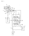
- FIG. 1 is a diagram showing a system configuration of a charge control device according to a preferred embodiment of the power generation control device of the present invention.
- reference numeral 1 denotes a generator.
- the generator 1 is composed of an inner rotor 2 and an outer stator 3.
- the inner rotor 2 is connected to one end of a crankshaft 5 of a four-stroke cycle engine 4.
- the outer stator 3 has a three-phase output winding 6, which is connected to the input side of a switching circuit 7.
- the output side of the switching circuit 7 is connected to a battery 8 and a load 9.
- the switching circuit 7 is a three-phase bridge circuit composed of six FETs 71, 72, 73, 74, 75, and 76.
- Reference numeral 10 denotes an FET driver as an output control device for changing the duty phases of the FETs 71 to 76 of the switching circuit 7 to thereby perform duty control.
- the inner rotor 2 of the generator 1 is provided with a sensor magnet 11 having a predetermined number of magnetic poles arranged in the circumferential direction thereof.
- the adjacent magnetic poles have different polarities.
- a crank angle sensor 12 is opposed to the circumferential surface of the sensor magnet 11.
- the crank angle sensor 12 is composed of a plurality of magnetoelectric transducers (Hall elements).
- the sensor magnet 11 has eight magnetic poles.
- the magnetic poles are arranged at 45° intervals.
- the crank angle sensor 12 has three Hall elements arranged at 15° intervals. These Hall elements successively output detection signals (which will be hereinafter referred to as "pitch signals”) at 15° intervals.
- the detection signals from the Hall elements are input into the FET driver 10.
- the FET driver 10 performs switching control in a predetermined stroke of the four strokes of the engine where the friction is low, according to engine speed, thus supplying a current I to the battery 8 and the load 9.
- the horizontal axis represents crank angle ⁇ and the vertical axis represents engine speed Ne.
- the horizontal axis is provided with a scale marked at 15° intervals in accordance with the output from the crank angle sensor 12. The left end of this scale corresponds to the compression top dead center (top position).
- a plurality of charge periods, or power generation periods are shown along this scale, and these charge periods are different according to engine speed Ne. More specifically, different charge periods A, B, C, D, and E are set according to engine speed Ne.
- the charge period A is set to a range from the initial stage of the expansion stroke to the initial stage of the exhaust stroke (crank angle of 30° to 210°).
- the charge period B is set to a range slightly delayed from the charge period A (crank angle of 45° to 240°).
- the charge period C is set to a range from the middle of the expansion stroke to the end of the exhaust stroke (crank angle of 90° to 360°).
- the charge period D is set to a range from the middle of the expansion stroke to the end of the intake stroke (crank angle of 90° to 540°).
- charging is performed in only the limited different ranges starting from the expansion stroke of the four strokes in a predetermined engine speed region from a predetermined idling speed NeID to a predetermined normal charge starting speed NeCH higher than the idling speed NeID.
- the charge period E is set to a range including all of the four strokes, so that charge control is performed in all of the four strokes according to load condition and battery voltage.
- FIG. 3 is a graph showing the basic output characteristic of the generator 1.
- the horizontal axis represents engine speed Ne and the vertical axis represents output current I.
- the engine speed Ne reaches the idling speed NeID
- charging is started.
- the normal charge starting speed NeCH normal charge is not performed, that is, charging is performed in only the predetermined charge periods as described above with reference to FIG. 2 (which will be hereinafter referred to as "periodic charge").
- the periodic charge is ended and the charge amount is controlled in all of the four strokes of the engine according to load condition and battery voltage.
- the engine speed region from the idling speed NeID to the normal charge starting speed NeCH is referred to as a periodic charge region, and the engine speed region higher than the normal charge starting speed NeCH is referred to as a normal charge region.
- FIG. 4 is a block diagram showing the function of an essential part of the FET driver 10. As shown in FIG. 4 , the FET driver 10 includes a charge period control block 101, regulated voltage control block 102, duty setting means 103, and AND gate 104.
- the charge period control block 101 includes a mechanical angle counter 13, top dead center detecting means 14, crank angle detecting means 15, engine speed detecting means 16, charge period storing means 17, and charge period determining means 18.
- the mechanical angle counter 13 is composed of a first counter 131 for counting pitch signals input at 15° intervals and a second counter 132 incrementing its counter value by 1 every time six pitch signals are counted by the first counter 131.
- the counter value of the second counter 132 is increased one by one at 90° intervals.
- the initial value of the counter value of the second counter 132 is "0", and the maximum value of the counter value of the second counter 132 is "7". Accordingly, the counter value of the second counter 132 is circulated at 720° intervals, i.e., with the cycle of the four strokes of the engine 4.
- the top dead center detecting means 14 decides the compression top dead center at the position where the counter value of the second counter 132 is "0". However, the compression top dead center cannot be determined only by the counter value of the second counter 132. In this preferred embodiment, the compression top dead center is determined by the counter value of the second counter 132 and an external signal. As the external signal, an FI signal deciding a fuel injection timing in fuel injection control may be used. The FI signal is output in a predetermined period near the compression top dead center, so as to inject the fuel. Accordingly, when the increment of the counter value of the second counter 132 is detected in the output period of the FI signal, the timing of the increment of this counter value is determined as the compression top dead center. After the compression top dead center is determined, the counter value of the second counter 132 is reset to "0".
- the engine speed detecting means 16 monitors the period of the pitch signals and detects the engine speed Ne determined by this period.
- the charge period storing means 17 preliminarily stores a table showing the correspondence between the charge periods A to E and the engine speed Ne. Each charge period is set in units of 15°.
- the charge period storing means 17 When inputting an engine speed Ne from the engine speed detecting means 16, the charge period storing means 17 outputs data indicating the charge period corresponding to this engine speed Ne to the charge period determining means 18.
- the charge period determining means 18 compares the charge period input from the charge period storing means 17 and the crank angle input from the crank angle detecting means 15, and outputs a charge control signal in the case that the crank angle falls within the charge period.
- the regulated voltage control block 102 includes regulated voltage detecting means 19, regulated voltage setting means 20, voltage comparing means 21, and duty changing means 22.
- the regulated voltage setting means 20 preliminarily stores a regulated voltage set value Vref.
- the regulated voltage set value Vref is a predetermined battery voltage value of 14.5 V.
- the regulated voltage detecting means 19 detects a present battery voltage Vb as a regulated voltage and outputs it to the voltage comparing means 21.
- the voltage comparing means 21 compares the regulated voltage set value Vref and the detected voltage value Vb, and outputs the result of comparison to the duty changing means 22.
- the duty changing means 22 changes the duty of any one of the FETs according to the result of comparison between the input voltage values Vref and Vb. More specifically, when the detected voltage value Vb is smaller than the regulated voltage set value Vref, the duty is increased, whereas when the detected voltage value Vb is larger than the regulated voltage set value Vref, the duty is decreased.
- the duty changing means 22 outputs a duty changing signal for increasing or decreasing the duty as mentioned above.
- the amount of change in the duty may be a fixed value or may be variable according to the deviation of the detected voltage value Vb from the regulated voltage set value Vref. More specifically, when the deviation is large, the amount of change in the duty may be increased, whereas when the deviation is small, the amount of change in the duty may be decreased.
- the duty changing signal is input into the duty setting means 103.
- the duty setting means 103 outputs the duty changed above and a drive command for the switching circuit 7 to the AND gate 104.
- the charge control signal from the charge period determining means 18 is input as a gate signal into the AND gate 104. Accordingly, while the charge control signal is ON, the duty and the drive command for the switching circuit 7 output from the duty setting means 103 are input into the switching circuit 7.
- the switching circuit 7 is driven in response to the drive signal output from the duty setting means 103, and a given one of the FETs 71 to 76 is kept on during the phase according to the input duty in accordance with a predetermined switching pattern. While this FET is ON, the current generated in the three-phase output winding 6 of the generator 1 is supplied to the battery 8 and the load 9.
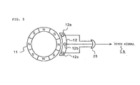
- FIG. 5 is a schematic diagram showing the positional relation between the crank angle sensor 12 and the sensor magnet 11.
- the sensor magnet 11 is a ringlike permanent magnet, which has a plurality of N poles and S poles alternately arranged at 45° intervals.
- the crank angle sensor 12 is composed of three Hall elements 12a, 12b, and 12c opposed to the outer circumferential surface of the sensor magnet 11. These three Hall elements 12a, 12b, and 12c are arranged at 15° intervals. Outputs from the Hall elements 12a, 12b, and 12c are input through an OR gate 25 to the first counter 131. In other words, the pitch signals are formed at 15° intervals according to the positional relation between the sensor magnet 11 and the Hall elements 12a to 12c.
- FIG. 6 is a schematic diagram for illustrating the operation of the top dead center detecting means 14. As shown in FIG. 6 , every time six pitch signals are detected (i.e., every time a mechanical angle of 90° is detected), the counter value of the second counter 132 is incremented from “0" to "7", and this cycle is repeated. Further, while the FI signal is ON, the counter value of the second counter 132 is reset to "0".
- the temporary counter value prior to resetting shown at the top position in FIG. 6 and the FI signal shown at the middle position in FIG. 6 are put into AND to obtain a decisive counter value shown at the bottom position in FIG. 6 .
- the counter values 0 to 2 are determined as the expansion stroke
- the counter values 2 to 4 are determined as the exhaust stroke
- the counter values 4 to 6 are determined as the intake stroke
- the counter values 6 to 8 are determined as the compression stroke.
- the switching circuit 7 performs switching of the FETs 71 to 76 in accordance with a predetermined switching pattern to convert the current generated by the generator 1 into a direct current.
- a masking pattern is preliminarily set in a time period other than the charge periods A to D, and all the FETs 71 to 76 are turned off in this time period to thereby stop the output from the generator 1.
- the regulated voltage detecting means 19 reads a plurality of voltage values for the battery voltage in each stroke of the engine and detects the average of these voltage values as the battery voltage (regulated voltage).
- This average may be weighted according to the charge periods A to E. More specifically, when charging is performed in only the charge periods A to D of all the engine strokes, the average is multiplied by a coefficient less than 1.0, whereas when charging is performed in all the engine strokes (the charge period E), the average is multiplied by a coefficient of 1.0.
- the top dead center detecting means 14 detects the top dead center by performing an AND operation between the temporary counter value and the FI signal at 90° intervals to thereby obtain the decisive counter value.
- the top dead center may be determined by calculating an average of engine speeds at 90° intervals and setting the counter value "0" at the mechanical angle where the difference in this average in all the engine strokes becomes maximum. This modification is suitable for an engine with a carburetor in which the FI signal cannot be obtained.
- the engine strokes are detected and a predetermined region of the engine strokes where the friction is low is set as a charge period.
- the charge period may be made variable in consideration of load condition. For example, a crank angular velocity in the predetermined region prior to the compression stroke may be detected, and if the crank angular velocity detected above is less than a reference value, it is determined that the load is high, so that the charge period is shortened. More specifically, even though the charge period is set to the charge period D determind by a certain engine speed, for example, the charge period is shortened to stop charging at the end of the exhaust stroke rather than at the end of the intake stroke in the case that the load is determined to be high.
- the charge period is varied to the charge period C. Further, even though the charge period is set to the charge period C determined by a lower engine speed, the charge period is shortened to stop charging at the initial stage of the exhaust stroke rather than at the end of the exhaust stroke in the case that the load is determined to be high. In other words, the charge period is varied to the charge period A or B.
- the invention is directed to reduce engine torque fluctuations due to load by power generation and perform minimum power generation.
- An engine speed Ne and a crank angle based on a top dead center are detected by using pitch signals input from a crank angle sensor 12.
- Charge period storing means 17 preliminarily stores a plurality of charge periods different in length as a function of engine speed Ne. These charge periods correspond to some of the four strokes of the engine where the friction is low.
- Charge period determining means 18 compares a present crank angle and a charge period corresponding to a present engine speed and outputs a charge control signal to an AND gate 104 when the present crank angle falls within this charge period.
- a duty decided by a regulated voltage control block 102 is input into duty setting means 103. When the AND gate 104 is opened, the duty from the duty setting means 103 is input into a switching circuit 7.
Landscapes
- Engineering & Computer Science (AREA)
- Power Engineering (AREA)
- Control Of Eletrric Generators (AREA)
- Control Of Charge By Means Of Generators (AREA)
Abstract
Description
- The present invention relates to a power generation control device, and more particularly to a power generation control device for controlling power generation so that an output current generated from an engine driven generator is supplied to a battery and a load in only a predetermined region in the engine strokes where a friction in the engine is low.
- In a vehicle adapted to be driven by an engine, such as a motorcycle and a four-wheel vehicle, a generator adapted to be driven by the engine is provided. A battery for supplying electric power to be used in the vehicle is charged with an output current generated from the generator. Further, in general, an on-vehicle generator serves also as an engine starting motor.
- It is known that the amount of power generation by an on-vehicle generator is variably controlled according to load on an engine in the vehicle. For example, Patent Document No.
JP-A-3-504407 - Further, Patent Literature No.
JP-A-3-212200 - In the existing power generation control device or charge control device as described in Patent Document No.
JP-A-3-504407 JP-A-3-212200 - Particularly in the case that the engine is operated in a low engine speed region, the output torque of the engine is generally low. Accordingly, even though the amount of power generation is limited, there is a possibility that the engine operation may become unstable due to the torque fluctuations caused by the difference in friction between the strokes. In other words, there is a case that even though the amount of power generation is controlled according to only the loaded condition of an engine in general, the smoothness of the engine operation cannot be largely improved.
- It is accordingly an object of the present invention to provide a power generation control device which can smooth the torque particularly in a low engine speed region by controlling the amount of power generation in consideration of the friction in each stroke.
- In accordance with a first aspect of the present invention, there is provided a power generation control device for a generator adapted to be driven by a four-stroke cycle engine, the power generation control device including a switching circuit for controlling an output current from the generator; and power generation period control means for operating the switching circuit in only a predetermined power generation period in the four strokes of the engine; wherein the power generation period ranges from the expansion stroke to the intake stroke of the four strokes.
- In accordance with a second aspect of the present invention, the power generation period is set according to engine speed so that the lower the engine speed, the more the start of the power generation period is shifted toward the expansion stroke and the shorter the range of the power generation period.
- In accordance with a third aspect of the present invention, the power generation period is effective only between a predetermined idling speed and a predetermined charge starting speed higher than the idling speed; and the switching circuit is operated in all of the four strokes in an engine speed region higher than or equal to the charge starting speed to thereby perform power generation control in all of the four strokes.
- In accordance with a fourth aspect of the present invention, the generator is connected to a battery adapted to be charged by the output current from the generator; and the switching circuit is driven in accordance with a duty decided so that a terminal voltage of the battery is converged to a predetermined regulated voltage.
- According to the first aspect, power generation is performed in only the power generation period set in the range from the expansion stroke to the intake stroke where the friction is low, so that a load due to this power generation is added to the friction in the engine itself. Accordingly, the torque can be made uniform between these strokes where the friction is low and the other stroke where the friction is large, thereby stabilizing an intake efficiency.
- According to the second aspect, the lower the engine speed, the shorter the range of the power generation period. In particular, power generation is performed in the expansion stroke where the friction is lower. Accordingly, the influence of load due to the power generation can be minimized and minimum power generation can be performed at the same time. Further, fuel economy can be improved by such minimum power generation.
- According to the third aspect, power generation is performed only in a relatively low engine speed region ranging from the idling speed to the charge starting speed. Accordingly, as compared with the case that power generation is performed in a low engine speed region with low torque over the four strokes, an increase in load due to power generation can be suppressed. Accordingly, engine operation in the low engine speed region can be stabilized.
- According to the fourth aspect, in a system for supplying electric power generated from the generator to the battery, charge control of the battery can be performed with reference to the predetermined regulated voltage.
-
-
FIG. 1 is a diagram showing a system configuration of a charge control device according to a preferred embodiment of the present invention. -
FIG. 2 is a diagram showing the relation between engine speed and charge period according to the preferred embodiment. -
FIG. 3 is a graph showing the output characteristic of a generator. -
FIG. 4 is a block diagram showing the function of an essential part of an FET driver. -
FIG. 5 is a schematic diagram showing the positional relation between a crank angle sensor and a sensor magnet. -
FIG. 6 is a schematic diagram for illustrating the operation of top dead center detecting means. - A preferred embodiment of the present invention will now be described with reference to the drawings.
FIG. 1 is a diagram showing a system configuration of a charge control device according to a preferred embodiment of the power generation control device of the present invention. - In
FIG. 1 ,reference numeral 1 denotes a generator. Thegenerator 1 is composed of aninner rotor 2 and anouter stator 3. Theinner rotor 2 is connected to one end of acrankshaft 5 of a four-stroke cycle engine 4. Theouter stator 3 has a three-phase output winding 6, which is connected to the input side of aswitching circuit 7. The output side of theswitching circuit 7 is connected to abattery 8 and a load 9. Theswitching circuit 7 is a three-phase bridge circuit composed of sixFETs Reference numeral 10 denotes an FET driver as an output control device for changing the duty phases of theFETs 71 to 76 of theswitching circuit 7 to thereby perform duty control. - The
inner rotor 2 of thegenerator 1 is provided with asensor magnet 11 having a predetermined number of magnetic poles arranged in the circumferential direction thereof. The adjacent magnetic poles have different polarities. Acrank angle sensor 12 is opposed to the circumferential surface of thesensor magnet 11. Thecrank angle sensor 12 is composed of a plurality of magnetoelectric transducers (Hall elements). In this preferred embodiment, thesensor magnet 11 has eight magnetic poles. In other words, the magnetic poles are arranged at 45° intervals. On the other hand, thecrank angle sensor 12 has three Hall elements arranged at 15° intervals. These Hall elements successively output detection signals (which will be hereinafter referred to as "pitch signals") at 15° intervals. The detection signals from the Hall elements are input into theFET driver 10. - The FET
driver 10 performs switching control in a predetermined stroke of the four strokes of the engine where the friction is low, according to engine speed, thus supplying a current I to thebattery 8 and the load 9. - The outline of the charge control in this preferred embodiment will now be described with reference to
FIG. 2 . InFIG. 2 , the horizontal axis represents crank angle α and the vertical axis represents engine speed Ne. The horizontal axis is provided with a scale marked at 15° intervals in accordance with the output from thecrank angle sensor 12. The left end of this scale corresponds to the compression top dead center (top position). When thecrankshaft 5 of theengine 4 is rotated, an expansion stroke, exhaust stroke, intake stroke, and compression stroke are successively repeated at 180° intervals from the top position as a start point. - A plurality of charge periods, or power generation periods are shown along this scale, and these charge periods are different according to engine speed Ne. More specifically, different charge periods A, B, C, D, and E are set according to engine speed Ne. The charge period A is set to a range from the initial stage of the expansion stroke to the initial stage of the exhaust stroke (crank angle of 30° to 210°). The charge period B is set to a range slightly delayed from the charge period A (crank angle of 45° to 240°). The charge period C is set to a range from the middle of the expansion stroke to the end of the exhaust stroke (crank angle of 90° to 360°). The charge period D is set to a range from the middle of the expansion stroke to the end of the intake stroke (crank angle of 90° to 540°). In this manner, charging is performed in only the limited different ranges starting from the expansion stroke of the four strokes in a predetermined engine speed region from a predetermined idling speed NeID to a predetermined normal charge starting speed NeCH higher than the idling speed NeID. In an engine speed region higher than the normal charge starting speed NeCH, the charge period E is set to a range including all of the four strokes, so that charge control is performed in all of the four strokes according to load condition and battery voltage.
- In the expansion stroke, maximum torque can be obtained by the combustion of fuel in the engine, so that there is a low possibility that the engine speed may become unstable when a load due to power generation is applied to the engine. In the compression stroke, the friction is large and the torque is low, so that the load due to power generation has a large effect on the engine speed. In this preferred embodiment, when the engine speed Ne is less than the normal charge starting speed NeCH, charging is stopped in the compression stroke where the load due to power generation has a large effect on the engine speed, whereas charging is performed in only the expansion stroke to the intake stroke where the load due to power generation has a small effect on the engine speed.
-
FIG. 3 is a graph showing the basic output characteristic of thegenerator 1. InFIG. 3 , the horizontal axis represents engine speed Ne and the vertical axis represents output current I. As apparent fromFIG. 3 , when the engine speed Ne reaches the idling speed NeID, charging is started. Until the engine speed Ne reaches the normal charge starting speed NeCH, normal charge is not performed, that is, charging is performed in only the predetermined charge periods as described above with reference toFIG. 2 (which will be hereinafter referred to as "periodic charge"). When the engine speed Ne reaches the normal charge starting speed NeCH, the periodic charge is ended and the charge amount is controlled in all of the four strokes of the engine according to load condition and battery voltage. The engine speed region from the idling speed NeID to the normal charge starting speed NeCH is referred to as a periodic charge region, and the engine speed region higher than the normal charge starting speed NeCH is referred to as a normal charge region. -
FIG. 4 is a block diagram showing the function of an essential part of theFET driver 10. As shown inFIG. 4 , theFET driver 10 includes a chargeperiod control block 101, regulatedvoltage control block 102, duty setting means 103, and ANDgate 104. - The charge
period control block 101 includes amechanical angle counter 13, top dead center detecting means 14, crankangle detecting means 15, enginespeed detecting means 16, charge period storing means 17, and chargeperiod determining means 18. - The
mechanical angle counter 13 is composed of afirst counter 131 for counting pitch signals input at 15° intervals and asecond counter 132 incrementing its counter value by 1 every time six pitch signals are counted by thefirst counter 131. In other words, the counter value of thesecond counter 132 is increased one by one at 90° intervals. The initial value of the counter value of thesecond counter 132 is "0", and the maximum value of the counter value of thesecond counter 132 is "7". Accordingly, the counter value of thesecond counter 132 is circulated at 720° intervals, i.e., with the cycle of the four strokes of theengine 4. - The top dead center detecting means 14 decides the compression top dead center at the position where the counter value of the
second counter 132 is "0". However, the compression top dead center cannot be determined only by the counter value of thesecond counter 132. In this preferred embodiment, the compression top dead center is determined by the counter value of thesecond counter 132 and an external signal. As the external signal, an FI signal deciding a fuel injection timing in fuel injection control may be used. The FI signal is output in a predetermined period near the compression top dead center, so as to inject the fuel. Accordingly, when the increment of the counter value of thesecond counter 132 is detected in the output period of the FI signal, the timing of the increment of this counter value is determined as the compression top dead center. After the compression top dead center is determined, the counter value of thesecond counter 132 is reset to "0". - The crank
angle detecting means 15 detects a crank angle with reference to the compression top dead center according to the counter value from thesecond counter 132 of themechanical angle counter 13 and the pitch signals. For example, in the case that three pitch signals are input from the time the counter value "0" is input, the crank angle is detected as 45° (0° + 15° x 3 = 45°). In the case that four pitch signals are input from the time the counter value "2" is input, the crank angle is detected as 240° (90° x 2 + 15° x 4 = 240°). - The engine
speed detecting means 16 monitors the period of the pitch signals and detects the engine speed Ne determined by this period. The charge period storing means 17 preliminarily stores a table showing the correspondence between the charge periods A to E and the engine speed Ne. Each charge period is set in units of 15°. When inputting an engine speed Ne from the enginespeed detecting means 16, the charge period storing means 17 outputs data indicating the charge period corresponding to this engine speed Ne to the chargeperiod determining means 18. The chargeperiod determining means 18 compares the charge period input from the charge period storing means 17 and the crank angle input from the crankangle detecting means 15, and outputs a charge control signal in the case that the crank angle falls within the charge period. - The regulated
voltage control block 102 includes regulatedvoltage detecting means 19, regulated voltage setting means 20,voltage comparing means 21, andduty changing means 22. The regulated voltage setting means 20 preliminarily stores a regulated voltage set value Vref. The regulated voltage set value Vref is a predetermined battery voltage value of 14.5 V. The regulatedvoltage detecting means 19 detects a present battery voltage Vb as a regulated voltage and outputs it to thevoltage comparing means 21. Thevoltage comparing means 21 compares the regulated voltage set value Vref and the detected voltage value Vb, and outputs the result of comparison to theduty changing means 22. - The duty changing means 22 changes the duty of any one of the FETs according to the result of comparison between the input voltage values Vref and Vb. More specifically, when the detected voltage value Vb is smaller than the regulated voltage set value Vref, the duty is increased, whereas when the detected voltage value Vb is larger than the regulated voltage set value Vref, the duty is decreased. The duty changing means 22 outputs a duty changing signal for increasing or decreasing the duty as mentioned above. The amount of change in the duty may be a fixed value or may be variable according to the deviation of the detected voltage value Vb from the regulated voltage set value Vref. More specifically, when the deviation is large, the amount of change in the duty may be increased, whereas when the deviation is small, the amount of change in the duty may be decreased. The duty changing signal is input into the duty setting means 103. The duty setting means 103 outputs the duty changed above and a drive command for the
switching circuit 7 to the ANDgate 104. - On the other hand, the charge control signal from the charge
period determining means 18 is input as a gate signal into the ANDgate 104. Accordingly, while the charge control signal is ON, the duty and the drive command for theswitching circuit 7 output from the duty setting means 103 are input into theswitching circuit 7. Theswitching circuit 7 is driven in response to the drive signal output from the duty setting means 103, and a given one of theFETs 71 to 76 is kept on during the phase according to the input duty in accordance with a predetermined switching pattern. While this FET is ON, the current generated in the three-phase output winding 6 of thegenerator 1 is supplied to thebattery 8 and the load 9. -
FIG. 5 is a schematic diagram showing the positional relation between thecrank angle sensor 12 and thesensor magnet 11. As shown inFIG. 5 , thesensor magnet 11 is a ringlike permanent magnet, which has a plurality of N poles and S poles alternately arranged at 45° intervals. Thecrank angle sensor 12 is composed of threeHall elements sensor magnet 11. These threeHall elements Hall elements OR gate 25 to thefirst counter 131. In other words, the pitch signals are formed at 15° intervals according to the positional relation between thesensor magnet 11 and theHall elements 12a to 12c. -
FIG. 6 is a schematic diagram for illustrating the operation of the top deadcenter detecting means 14. As shown inFIG. 6 , every time six pitch signals are detected (i.e., every time a mechanical angle of 90° is detected), the counter value of thesecond counter 132 is incremented from "0" to "7", and this cycle is repeated. Further, while the FI signal is ON, the counter value of thesecond counter 132 is reset to "0". - More specifically, the temporary counter value prior to resetting shown at the top position in
FIG. 6 and the FI signal shown at the middle position inFIG. 6 are put into AND to obtain a decisive counter value shown at the bottom position inFIG. 6 . As a result, the counter values 0 to 2 are determined as the expansion stroke, the counter values 2 to 4 are determined as the exhaust stroke, the counter values 4 to 6 are determined as the intake stroke, and the counter values 6 to 8 are determined as the compression stroke. - The
switching circuit 7 performs switching of theFETs 71 to 76 in accordance with a predetermined switching pattern to convert the current generated by thegenerator 1 into a direct current. In a low engine speed region from the idling speed NeID to the normal charge starting speed NeCH, charging is performed in only the charge periods A to D. Accordingly, a masking pattern is preliminarily set in a time period other than the charge periods A to D, and all the FETs 71 to 76 are turned off in this time period to thereby stop the output from thegenerator 1. - As described above, the charging current is changed according to engine stroke, resulting in variations in battery voltage. To cope with this problem, the regulated voltage detecting means 19 reads a plurality of voltage values for the battery voltage in each stroke of the engine and detects the average of these voltage values as the battery voltage (regulated voltage). This average may be weighted according to the charge periods A to E. More specifically, when charging is performed in only the charge periods A to D of all the engine strokes, the average is multiplied by a coefficient less than 1.0, whereas when charging is performed in all the engine strokes (the charge period E), the average is multiplied by a coefficient of 1.0.
- As described above, the top dead center detecting means 14 detects the top dead center by performing an AND operation between the temporary counter value and the FI signal at 90° intervals to thereby obtain the decisive counter value. As a modification, the top dead center may be determined by calculating an average of engine speeds at 90° intervals and setting the counter value "0" at the mechanical angle where the difference in this average in all the engine strokes becomes maximum. This modification is suitable for an engine with a carburetor in which the FI signal cannot be obtained.
- In this preferred embodiment, the engine strokes are detected and a predetermined region of the engine strokes where the friction is low is set as a charge period. As a modification, the charge period may be made variable in consideration of load condition. For example, a crank angular velocity in the predetermined region prior to the compression stroke may be detected, and if the crank angular velocity detected above is less than a reference value, it is determined that the load is high, so that the charge period is shortened. More specifically, even though the charge period is set to the charge period D determind by a certain engine speed, for example, the charge period is shortened to stop charging at the end of the exhaust stroke rather than at the end of the intake stroke in the case that the load is determined to be high. In other words, the charge period is varied to the charge period C. Further, even though the charge period is set to the charge period C determined by a lower engine speed, the charge period is shortened to stop charging at the initial stage of the exhaust stroke rather than at the end of the exhaust stroke in the case that the load is determined to be high. In other words, the charge period is varied to the charge period A or B.
- The invention is directed to reduce engine torque fluctuations due to load by power generation and perform minimum power generation.
- An engine speed Ne and a crank angle based on a top dead center are detected by using pitch signals input from a
crank angle sensor 12. Charge period storing means 17 preliminarily stores a plurality of charge periods different in length as a function of engine speed Ne. These charge periods correspond to some of the four strokes of the engine where the friction is low. Chargeperiod determining means 18 compares a present crank angle and a charge period corresponding to a present engine speed and outputs a charge control signal to an ANDgate 104 when the present crank angle falls within this charge period. A duty decided by a regulatedvoltage control block 102 is input into duty setting means 103. When the ANDgate 104 is opened, the duty from the duty setting means 103 is input into aswitching circuit 7.
Claims (4)
- A power generation control device for a generator (1) adapted to be driven by a four-stroke cycle engine (4), said power generation control device comprising:a switching circuit (7) for controlling an output current from said generator (1); andpower generation period control means (10) for operating said switching circuit (7) in only a predetermined power generation period in the four strokes of said engine;wherein said power generation period ranges from the expansion stroke to the intake stroke of said four strokes.
- The power generation control device according to claim 1,
wherein
said power generation period is set according to engine speed so that the lower said engine speed, the more the start of said power generation period is shifted toward the expansion stroke and the shorter the range of said power generation period. - The power generation control device according to claim 1 or 2,
wherein:said power generation period is effective only between a predetermined idling speed and a predetermined charge starting speed higher than said idling speed; andsaid switching circuit (7) is operated in all of the four strokes in an engine speed region higher than or equal to said charge starting speed to thereby perform power generation control in all of the four strokes. - The power generation control device according to any one of claims 1 to 3, wherein:said generator (1) is connected to a battery (8) adapted to be charged by the output current from said generator (1); andsaid switching circuit (7) is driven in accordance with a duty decided so that a terminal voltage of said battery (8) is converged to a predetermined regulated voltage.
Applications Claiming Priority (1)
| Application Number | Priority Date | Filing Date | Title |
|---|---|---|---|
| JP2007247867A JP5158682B2 (en) | 2007-09-25 | 2007-09-25 | Power generation control device |
Publications (2)
| Publication Number | Publication Date |
|---|---|
| EP2068437A1 true EP2068437A1 (en) | 2009-06-10 |
| EP2068437B1 EP2068437B1 (en) | 2010-03-17 |
Family
ID=39832432
Family Applications (1)
| Application Number | Title | Priority Date | Filing Date |
|---|---|---|---|
| EP08012943A Not-in-force EP2068437B1 (en) | 2007-09-25 | 2008-07-17 | Control device for a generator driven by a four-stroke cycle engine |
Country Status (9)
| Country | Link |
|---|---|
| US (1) | US7982324B2 (en) |
| EP (1) | EP2068437B1 (en) |
| JP (1) | JP5158682B2 (en) |
| KR (1) | KR20090031809A (en) |
| CN (1) | CN101399460B (en) |
| CA (1) | CA2636971C (en) |
| DE (1) | DE602008000835D1 (en) |
| ES (1) | ES2341304T3 (en) |
| TW (1) | TWI412225B (en) |
Families Citing this family (7)
| Publication number | Priority date | Publication date | Assignee | Title |
|---|---|---|---|---|
| JP5035895B2 (en) * | 2007-09-27 | 2012-09-26 | 本田技研工業株式会社 | Power generation control device |
| JP5283259B2 (en) * | 2008-09-19 | 2013-09-04 | 本田技研工業株式会社 | Power generation control device |
| CN102396148B (en) * | 2009-04-16 | 2014-06-18 | 株式会社电装 | Power-generation control device |
| JP5382202B2 (en) * | 2010-03-25 | 2014-01-08 | トヨタ自動車株式会社 | Vehicle regeneration control system |
| CN103061943B (en) * | 2013-01-05 | 2016-03-23 | 广东康菱动力科技有限公司 | High-voltage large-capacity motor emergency starting generator set and starting method |
| JP6301240B2 (en) * | 2014-02-07 | 2018-03-28 | 本田技研工業株式会社 | Battery charger for vehicle |
| JP2018053774A (en) * | 2016-09-28 | 2018-04-05 | ヤマハ発動機株式会社 | Vehicle |
Citations (5)
| Publication number | Priority date | Publication date | Assignee | Title |
|---|---|---|---|---|
| JPH03212200A (en) | 1990-01-17 | 1991-09-17 | Hitachi Ltd | Generator controller, control method and application thereof on vehicle generator controller and control method |
| JPH03504407A (en) | 1988-05-25 | 1991-09-26 | ヨシダ,ルイス,ティー. | Method and apparatus for managing alternator load on engine |
| US5608309A (en) * | 1993-02-24 | 1997-03-04 | Hitachi, Ltd. | Vehicle-use alternating current generator control system |
| EP1102381A1 (en) * | 1999-11-20 | 2001-05-23 | MAN Nutzfahrzeuge Aktiengesellschaft | Voltage regulator for the alternator of a vehicle |
| US20040150233A1 (en) * | 2000-12-19 | 2004-08-05 | Denso Corporation | Vehicle motor-generator apparatus utilizing synchronous machine having field winding |
Family Cites Families (11)
| Publication number | Priority date | Publication date | Assignee | Title |
|---|---|---|---|---|
| JPH0834723B2 (en) * | 1986-12-22 | 1996-03-29 | 日本電装株式会社 | Generator control device mounted on the vehicle |
| JPH0691759B2 (en) * | 1988-08-12 | 1994-11-14 | 株式会社日立製作所 | Power generation control device for internal combustion engine |
| JPH09140196A (en) | 1995-11-14 | 1997-05-27 | Denso Corp | Power generation control device for vehicles |
| JP3784243B2 (en) * | 2000-06-30 | 2006-06-07 | 本田技研工業株式会社 | Engine drive power generator |
| JP3778342B2 (en) * | 2000-10-11 | 2006-05-24 | 本田技研工業株式会社 | Output generator for synchronous generator |
| JP2006129680A (en) * | 2004-11-01 | 2006-05-18 | Yamaha Motor Co Ltd | Generator control device, generator control method, and motorcycle |
| JP4487736B2 (en) * | 2004-11-12 | 2010-06-23 | 国産電機株式会社 | Battery charger |
| US8091519B2 (en) * | 2006-05-12 | 2012-01-10 | Bennion Robert F | Paired-piston linear engine |
| JP5035895B2 (en) * | 2007-09-27 | 2012-09-26 | 本田技研工業株式会社 | Power generation control device |
| JP5380927B2 (en) * | 2008-07-02 | 2014-01-08 | 株式会社デンソー | Power generation control device and power generation control system |
| JP2010016949A (en) * | 2008-07-02 | 2010-01-21 | Denso Corp | Power generation control device and power generation control system |
-
2007
- 2007-09-25 JP JP2007247867A patent/JP5158682B2/en not_active Expired - Fee Related
-
2008
- 2008-07-03 CA CA2636971A patent/CA2636971C/en not_active Expired - Fee Related
- 2008-07-17 EP EP08012943A patent/EP2068437B1/en not_active Not-in-force
- 2008-07-17 ES ES08012943T patent/ES2341304T3/en active Active
- 2008-07-17 DE DE602008000835T patent/DE602008000835D1/en active Active
- 2008-07-22 KR KR1020080071119A patent/KR20090031809A/en not_active Ceased
- 2008-07-23 CN CN2008101316947A patent/CN101399460B/en not_active Expired - Fee Related
- 2008-07-24 TW TW097128182A patent/TWI412225B/en not_active IP Right Cessation
- 2008-09-22 US US12/235,398 patent/US7982324B2/en not_active Expired - Fee Related
Patent Citations (5)
| Publication number | Priority date | Publication date | Assignee | Title |
|---|---|---|---|---|
| JPH03504407A (en) | 1988-05-25 | 1991-09-26 | ヨシダ,ルイス,ティー. | Method and apparatus for managing alternator load on engine |
| JPH03212200A (en) | 1990-01-17 | 1991-09-17 | Hitachi Ltd | Generator controller, control method and application thereof on vehicle generator controller and control method |
| US5608309A (en) * | 1993-02-24 | 1997-03-04 | Hitachi, Ltd. | Vehicle-use alternating current generator control system |
| EP1102381A1 (en) * | 1999-11-20 | 2001-05-23 | MAN Nutzfahrzeuge Aktiengesellschaft | Voltage regulator for the alternator of a vehicle |
| US20040150233A1 (en) * | 2000-12-19 | 2004-08-05 | Denso Corporation | Vehicle motor-generator apparatus utilizing synchronous machine having field winding |
Also Published As
| Publication number | Publication date |
|---|---|
| KR20090031809A (en) | 2009-03-30 |
| CN101399460A (en) | 2009-04-01 |
| US20090079190A1 (en) | 2009-03-26 |
| DE602008000835D1 (en) | 2010-04-29 |
| JP2009081916A (en) | 2009-04-16 |
| TWI412225B (en) | 2013-10-11 |
| JP5158682B2 (en) | 2013-03-06 |
| ES2341304T3 (en) | 2010-06-17 |
| CA2636971A1 (en) | 2009-03-25 |
| CA2636971C (en) | 2012-04-10 |
| US7982324B2 (en) | 2011-07-19 |
| TW200922111A (en) | 2009-05-16 |
| CN101399460B (en) | 2011-09-07 |
| EP2068437B1 (en) | 2010-03-17 |
Similar Documents
| Publication | Publication Date | Title |
|---|---|---|
| EP2068437B1 (en) | Control device for a generator driven by a four-stroke cycle engine | |
| JP5035895B2 (en) | Power generation control device | |
| US7443044B2 (en) | Engine control device | |
| JP2528995B2 (en) | In-vehicle generator control system | |
| US7081738B2 (en) | Generating device having magneto generator | |
| US20050120782A1 (en) | Engine rotation information detection device | |
| CN105874189B (en) | Engine unit and vehicle | |
| CN1507146A (en) | Generator-motor systems for vehicles | |
| JP4577031B2 (en) | Ignition device for internal combustion engine | |
| TWI646257B (en) | Engine control device, engine unit and vehicle | |
| CN102396148B (en) | Power-generation control device | |
| JP5283259B2 (en) | Power generation control device | |
| JP4468969B2 (en) | Control device for internal combustion engine | |
| JP5446449B2 (en) | Power generation control device | |
| JP4947033B2 (en) | Vehicle power generation control device and vehicle power generation control system | |
| JPH05302526A (en) | Device for restraining variation in engine speed | |
| JP4973639B2 (en) | Charge control device and charge control system | |
| JP5380927B2 (en) | Power generation control device and power generation control system | |
| CN103582998B (en) | Drive control device and power generation control method | |
| JP2010016949A (en) | Power generation control device and power generation control system | |
| EP3647575A1 (en) | Engine rotational speed variation amount detecting device and engine control device | |
| US20230179000A1 (en) | Battery string state of charge balancing with phase sharing | |
| JP2021087311A (en) | Control device for vehicle | |
| JP5637742B2 (en) | Method for controlling generator of internal combustion engine | |
| JPS61135936A (en) | Torque fluctuation reducing device for internal combustion engine |
Legal Events
| Date | Code | Title | Description |
|---|---|---|---|
| PUAI | Public reference made under article 153(3) epc to a published international application that has entered the european phase |
Free format text: ORIGINAL CODE: 0009012 |
|
| 17P | Request for examination filed |
Effective date: 20080717 |
|
| AK | Designated contracting states |
Kind code of ref document: A1 Designated state(s): AT BE BG CH CY CZ DE DK EE ES FI FR GB GR HR HU IE IS IT LI LT LU LV MC MT NL NO PL PT RO SE SI SK TR |
|
| AX | Request for extension of the european patent |
Extension state: AL BA MK RS |
|
| GRAP | Despatch of communication of intention to grant a patent |
Free format text: ORIGINAL CODE: EPIDOSNIGR1 |
|
| GRAS | Grant fee paid |
Free format text: ORIGINAL CODE: EPIDOSNIGR3 |
|
| RAP1 | Party data changed (applicant data changed or rights of an application transferred) |
Owner name: HONDA MOTOR CO., LTD. |
|
| GRAA | (expected) grant |
Free format text: ORIGINAL CODE: 0009210 |
|
| AKX | Designation fees paid |
Designated state(s): DE ES FR IT |
|
| AK | Designated contracting states |
Kind code of ref document: B1 Designated state(s): DE ES FR IT |
|
| REF | Corresponds to: |
Ref document number: 602008000835 Country of ref document: DE Date of ref document: 20100429 Kind code of ref document: P |
|
| REG | Reference to a national code |
Ref country code: ES Ref legal event code: FG2A Ref document number: 2341304 Country of ref document: ES Kind code of ref document: T3 |
|
| PLBE | No opposition filed within time limit |
Free format text: ORIGINAL CODE: 0009261 |
|
| STAA | Information on the status of an ep patent application or granted ep patent |
Free format text: STATUS: NO OPPOSITION FILED WITHIN TIME LIMIT |
|
| 26N | No opposition filed |
Effective date: 20101220 |
|
| REG | Reference to a national code |
Ref country code: DE Ref legal event code: R084 Ref document number: 602008000835 Country of ref document: DE Effective date: 20140430 |
|
| REG | Reference to a national code |
Ref country code: FR Ref legal event code: PLFP Year of fee payment: 9 |
|
| PGFP | Annual fee paid to national office [announced via postgrant information from national office to epo] |
Ref country code: ES Payment date: 20160613 Year of fee payment: 9 |
|
| PGFP | Annual fee paid to national office [announced via postgrant information from national office to epo] |
Ref country code: FR Payment date: 20160613 Year of fee payment: 9 |
|
| PGFP | Annual fee paid to national office [announced via postgrant information from national office to epo] |
Ref country code: DE Payment date: 20160712 Year of fee payment: 9 Ref country code: IT Payment date: 20160720 Year of fee payment: 9 |
|
| REG | Reference to a national code |
Ref country code: DE Ref legal event code: R119 Ref document number: 602008000835 Country of ref document: DE |
|
| REG | Reference to a national code |
Ref country code: FR Ref legal event code: ST Effective date: 20180330 |
|
| PG25 | Lapsed in a contracting state [announced via postgrant information from national office to epo] |
Ref country code: DE Free format text: LAPSE BECAUSE OF NON-PAYMENT OF DUE FEES Effective date: 20180201 |
|
| PG25 | Lapsed in a contracting state [announced via postgrant information from national office to epo] |
Ref country code: FR Free format text: LAPSE BECAUSE OF NON-PAYMENT OF DUE FEES Effective date: 20170731 |
|
| PG25 | Lapsed in a contracting state [announced via postgrant information from national office to epo] |
Ref country code: IT Free format text: LAPSE BECAUSE OF NON-PAYMENT OF DUE FEES Effective date: 20170717 |
|
| REG | Reference to a national code |
Ref country code: ES Ref legal event code: FD2A Effective date: 20181105 |
|
| PG25 | Lapsed in a contracting state [announced via postgrant information from national office to epo] |
Ref country code: ES Free format text: LAPSE BECAUSE OF NON-PAYMENT OF DUE FEES Effective date: 20170718 |