EP2068429A2 - Systems and methods involving thyristors - Google Patents
Systems and methods involving thyristors Download PDFInfo
- Publication number
- EP2068429A2 EP2068429A2 EP08170282A EP08170282A EP2068429A2 EP 2068429 A2 EP2068429 A2 EP 2068429A2 EP 08170282 A EP08170282 A EP 08170282A EP 08170282 A EP08170282 A EP 08170282A EP 2068429 A2 EP2068429 A2 EP 2068429A2
- Authority
- EP
- European Patent Office
- Prior art keywords
- thyristor
- processor
- rowgoski
- measuring
- signal
- Prior art date
- Legal status (The legal status is an assumption and is not a legal conclusion. Google has not performed a legal analysis and makes no representation as to the accuracy of the status listed.)
- Withdrawn
Links
- 238000000034 method Methods 0.000 title claims description 49
- 238000004891 communication Methods 0.000 claims abstract description 12
- 238000010304 firing Methods 0.000 claims description 9
- 238000005070 sampling Methods 0.000 claims description 7
- 238000005259 measurement Methods 0.000 claims description 5
- 238000012545 processing Methods 0.000 claims description 4
- 230000001276 controlling effect Effects 0.000 description 25
- 230000005355 Hall effect Effects 0.000 description 4
- 239000004020 conductor Substances 0.000 description 2
- 230000010354 integration Effects 0.000 description 2
- 239000004065 semiconductor Substances 0.000 description 2
- RYGMFSIKBFXOCR-UHFFFAOYSA-N Copper Chemical compound [Cu] RYGMFSIKBFXOCR-UHFFFAOYSA-N 0.000 description 1
- XEEYBQQBJWHFJM-UHFFFAOYSA-N Iron Chemical group [Fe] XEEYBQQBJWHFJM-UHFFFAOYSA-N 0.000 description 1
- 230000003321 amplification Effects 0.000 description 1
- 238000006243 chemical reaction Methods 0.000 description 1
- 229910052802 copper Inorganic materials 0.000 description 1
- 239000010949 copper Substances 0.000 description 1
- 230000001419 dependent effect Effects 0.000 description 1
- 238000010586 diagram Methods 0.000 description 1
- 239000000835 fiber Substances 0.000 description 1
- 230000004907 flux Effects 0.000 description 1
- 238000009413 insulation Methods 0.000 description 1
- 238000003199 nucleic acid amplification method Methods 0.000 description 1
- 238000013021 overheating Methods 0.000 description 1
- 238000002360 preparation method Methods 0.000 description 1
- 230000001105 regulatory effect Effects 0.000 description 1
Images


Classifications
-
- H—ELECTRICITY
- H02—GENERATION; CONVERSION OR DISTRIBUTION OF ELECTRIC POWER
- H02M—APPARATUS FOR CONVERSION BETWEEN AC AND AC, BETWEEN AC AND DC, OR BETWEEN DC AND DC, AND FOR USE WITH MAINS OR SIMILAR POWER SUPPLY SYSTEMS; CONVERSION OF DC OR AC INPUT POWER INTO SURGE OUTPUT POWER; CONTROL OR REGULATION THEREOF
- H02M7/00—Conversion of AC power input into DC power output; Conversion of DC power input into AC power output
- H02M7/02—Conversion of AC power input into DC power output without possibility of reversal
- H02M7/04—Conversion of AC power input into DC power output without possibility of reversal by static converters
- H02M7/12—Conversion of AC power input into DC power output without possibility of reversal by static converters using discharge tubes with control electrode or semiconductor devices with control electrode
- H02M7/145—Conversion of AC power input into DC power output without possibility of reversal by static converters using discharge tubes with control electrode or semiconductor devices with control electrode using devices of a thyratron or thyristor type requiring extinguishing means
- H02M7/155—Conversion of AC power input into DC power output without possibility of reversal by static converters using discharge tubes with control electrode or semiconductor devices with control electrode using devices of a thyratron or thyristor type requiring extinguishing means using semiconductor devices only
- H02M7/162—Conversion of AC power input into DC power output without possibility of reversal by static converters using discharge tubes with control electrode or semiconductor devices with control electrode using devices of a thyratron or thyristor type requiring extinguishing means using semiconductor devices only in a bridge configuration
- H02M7/1623—Conversion of AC power input into DC power output without possibility of reversal by static converters using discharge tubes with control electrode or semiconductor devices with control electrode using devices of a thyratron or thyristor type requiring extinguishing means using semiconductor devices only in a bridge configuration with control circuit
-
- G—PHYSICS
- G01—MEASURING; TESTING
- G01R—MEASURING ELECTRIC VARIABLES; MEASURING MAGNETIC VARIABLES
- G01R15/00—Details of measuring arrangements of the types provided for in groups G01R17/00 - G01R29/00, G01R33/00 - G01R33/26 or G01R35/00
- G01R15/14—Adaptations providing voltage or current isolation, e.g. for high-voltage or high-current networks
- G01R15/18—Adaptations providing voltage or current isolation, e.g. for high-voltage or high-current networks using inductive devices, e.g. transformers
- G01R15/181—Adaptations providing voltage or current isolation, e.g. for high-voltage or high-current networks using inductive devices, e.g. transformers using coils without a magnetic core, e.g. Rogowski coils
-
- H—ELECTRICITY
- H02—GENERATION; CONVERSION OR DISTRIBUTION OF ELECTRIC POWER
- H02M—APPARATUS FOR CONVERSION BETWEEN AC AND AC, BETWEEN AC AND DC, OR BETWEEN DC AND DC, AND FOR USE WITH MAINS OR SIMILAR POWER SUPPLY SYSTEMS; CONVERSION OF DC OR AC INPUT POWER INTO SURGE OUTPUT POWER; CONTROL OR REGULATION THEREOF
- H02M1/00—Details of apparatus for conversion
- H02M1/0003—Details of control, feedback or regulation circuits
- H02M1/0009—Devices or circuits for detecting current in a converter
Definitions
- Embodiments relate generally to power semiconductor converters, and more particularly to measuring the current in thyristors and thyristor bridge circuits using Rowgoski coils.
- shunts are one method for diagnosing and controlling thyristor bridge circuits.
- shunts may be placed on the direct current (dc) output of the thyristor bridge circuit.
- the shunt wires are often subjected to high voltages. Thus, insulation failures may be prevalent. Shunts also consume large amounts of energy and are prone to overheating.
- Another method for diagnosing and controlling thyristor bridge circuits uses iron core alternating current (ac) transformers on the incoming ac busses of the thyristor bridge circuit.
- ac iron core alternating current
- Hall Effect current sensors may also be used to measure current in a thyristor bridge circuit.
- the Hall Effect current sensors are placed on the incoming ac bus or outgoing dc bus of each power converter.
- Hall Effect current sensors do not generally output a highly linear representation of current.
- Modified versions of Hall Effect current sensors (such as flux balance devices) are capable of linear operation over a specified range. They suffer from greater size and are more expensive than ac current transformers.
- An exemplary embodiment includes a system for measuring and controlling a thyristor comprising a thyristor, a Rowgoski coil in operable communication therewith the thyristor, and a processor operative to receive signals from the Rowgoski coil, determine an alternating current value, a direct current value of the thyristor, and control the thyristor.
- An exemplary method includes method for measuring the current in a thyristor, the method comprising integrating a signal received from a Rowgoski coil, wherein the Rowgoski coil is in operable communication therewith a thyristor, sending the signal to a processor, and processing the signal to determine an alternating current value and a direct current value in the thyristor with the processor.
- An alternate exempliary embodimetn of a system for measuring and controlling a thyristor bridge circuit comprising, a thyristor bridge circuit including a plurality of thyristors, a Rowgoski coil in operable communication therewith a thyristor of the plurality of thyristors, an analog to digital converter operative to receive scaled analog signals from the Rowgoski coil and convert the scaled analog signals to a digital format, a serial output unit operative to receive signals from the analog to digital converter and output signals via a first serial link, a processor operative to receive the signals from the serial output unit and determine an alternating current value and a direct current value of the thyristor, and wherein the processor is further operative to control the thyristor, and a thyristor gating unit operative to receive signals from the processor via a second serial link and to send gate firing pulses to the thyristor.
- a Rowgoski coil is a toroidal coil that may be coupled around a conductor. An alternating magnetic field produced by current in the conductor induces a voltage in the coil proportional to the rate of change of current.
- Rowgoski coils used in a thyristor bridge are relatively efficient and small compared to other types of current measuring devices. They are also easily insulated. These characteristics make using Rowgoski coils an attractive method for determining current in a thyristor and other types of power semiconductor converters.
- the illustrated embodiments show the use of Rowgoski coils to determine the ac and dc current in thyristors.
- the system 100 includes an exemplary thyristor bridge circuit 102 that comprises thyristors 104 connected to a dc circuit via connections 103.
- Rowgoski coils 106 are coupled to each of the thyristors 104.
- the Rowgoski coils 106 are used in a pulsed current position 105 of the thyristors 104 and are connected such that one Rowgoski coil 106 may monitor a pair of thyristors 104.
- Each of the thyristors 104 may be connected to an integrated amplifier 108.
- the outputs of the integrated amplifiers 108 are connected to an analog to digital converter 110 that is connected to a serial output device 112.
- the output of the serial output device 112 is connected to a processor 116 via a serial link 114.
- the processor 116 may be connected to a memory 118.
- the processor 116 is connected to a thyristor gating unit 120 via a serial link 122.
- the integrated amplifiers 108 receive voltage signals representing current derivatives from the Rogowski coils 106 and send integrated amplified signals to the analog to digital converter 110.
- the illustrated embodiment uses a delta-sigma method to convert the analog signal to a digital signal, however other embodiments may use any appropriate method for analog to digital conversion of the signal.
- the amplitude of the voltage sent by the Rogowski coils 106 may not require amplifying by the integrated amplifiers 108, thus some alternate embodiments may not include the integrated amplifiers 108 but may passively thus partially integrate the signal in preparation for further integration to be performed numerically in the processor 116.
- the signals are received by the serial output device 112 and sent to the processor 116 via the serial link 114.
- the signals received by the processor 116 may be stored in the memory 118.
- the signals received by the processor 116 from the serial link 114 may be further integrated to determine the ac current of the thyristors 104.
- the processor 116 is connected to the thyristor gating unit 120 with the copper based serial link 122. In alternate embodiments, the processor 116 may be connected to the thyristor gating unit 120 with any appropriate connection such as a fiber optic based serial connection, for example.
- the thyristor gating unit 120 is connected to the gate terminals 101 of the thyristors 104.
- the use of the serial link 122 allows the processor 116 to be located remotely from the thyristor gating unit 120 and the thyristors 104.
- the processor 116 may also be used to control a plurality of thyristor circuits via additional thyristor gating units similar to the thyristor gating unit 120 and serial signal inputs similar to the serial link 114.
- the illustrated embodiment includes a second serial link 123 that is connected to another thyristor gating unit (not shown) that may be similar to the thyristor gating unit 120.
- a serial link 115 is connected to another serial output device (not shown) may provide signals from another set of Rowgoski coils 105 (not shown).
- the Rowgoski coils 106 output a derivative of the current (di/dt) flowing through the thyristor 104.
- the signal must be integrated.
- the integrated signal yields a representation of the actual ac current flowing in the thyristor 104.
- the signal may be partially integrated by the integrated amplifier 108.
- the processor 116 may complete the integration of the signal.
- the illustrated embodiment includes the integrated amplifier 108, however, the in some alternate embodiments, the signal output by the Rowgoski coil 106 may not require amplification, but may require scaling. Thus, in alternate embodiments, the amplifier 108 may, for example scale the signal and perform other required signal attenuation.
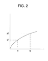
- FIG. 2 illustrates an example of a graph of an integrated output ac current signal.
- the processor 116 calculates the dc current of the thyristor 104 by sampling a first signal at a time (t1), wherein the first signal is a value (y1). In the illustrated embodiment, y1 is considered a zero current point regardless of the actual measured current at time tl.
- the processor 116 directs the thyristor 104 to gate at time (t2) and receives a second signal with a value of (y2). The processor 116 then takes the difference between the y2 and y1 values (y2-y1). The resultant difference is the dc current of the thyristor 104.
- FIG. 3 illustrates an alternate embodiment of a method that may be implemented by the processor 116 for determining the dc current of the thyristor 104.
- FIG. 3 includes a graph of an integrated output ac current signal.
- the second value (y2) may be a calculated average of measurements taken over a conduction interval (t3) of the thyristor. That is, a plurality of measurements spaced in time are acquired by the processor over t3 and averaged to form value y2. The result is a measured value of dc current for the thyristor more representative of actual current.
- the processor 116 uses the calculated current and voltage values of the thyristor 104 to determine the appropriate control signals to send to the thyristor gating unit 120.
- the thyristor gating unit 120 receives the control signals from the processor and generates firing pulses that are sent to the gate terminal 101 of the thyristor 104.
- the illustrated embodiment includes thyristors 104 that may be controlled by the processor 116, by controlling each of the thyristors 104, the processor may control the thyristor bridge circuit 102.
- the control may include, for example, actively balancing current, controlling the output voltage, and regulating the current.
Landscapes
- Engineering & Computer Science (AREA)
- Power Engineering (AREA)
- Rectifiers (AREA)
- Power Conversion In General (AREA)
- Arrangements For Transmission Of Measured Signals (AREA)
Abstract
Description
- Embodiments relate generally to power semiconductor converters, and more particularly to measuring the current in thyristors and thyristor bridge circuits using Rowgoski coils.
- In this regard, a variety of measurement schemes have been used to diagnose and control thyristor bridge circuits. Using shunts is one method for diagnosing and controlling thyristor bridge circuits. For control purposes, shunts may be placed on the direct current (dc) output of the thyristor bridge circuit. The shunt wires are often subjected to high voltages. Thus, insulation failures may be prevalent. Shunts also consume large amounts of energy and are prone to overheating.
- Another method for diagnosing and controlling thyristor bridge circuits uses iron core alternating current (ac) transformers on the incoming ac busses of the thyristor bridge circuit. To use this method, a cable or bus must be run through the transformers at the time of assembly. Measuring large currents on bus bars also requires large and expensive transformers.
- Hall Effect current sensors may also be used to measure current in a thyristor bridge circuit. The Hall Effect current sensors are placed on the incoming ac bus or outgoing dc bus of each power converter. However Hall Effect current sensors do not generally output a highly linear representation of current. Modified versions of Hall Effect current sensors (such as flux balance devices) are capable of linear operation over a specified range. They suffer from greater size and are more expensive than ac current transformers.
- Thus, it is desirable to use an apparatus and method for determining the ac and dc current in a thyristor circuit that does not require large or expensive components and outputs a linear representation of current. Additionally, it is desirable to us an apparatus and method that allows the current and voltage outputs of a thyristor circuit to be controlled by a remote processor.
- An exemplary embodiment includes a system for measuring and controlling a thyristor comprising a thyristor, a Rowgoski coil in operable communication therewith the thyristor, and a processor operative to receive signals from the Rowgoski coil, determine an alternating current value, a direct current value of the thyristor, and control the thyristor.
- An exemplary method includes method for measuring the current in a thyristor, the method comprising integrating a signal received from a Rowgoski coil, wherein the Rowgoski coil is in operable communication therewith a thyristor, sending the signal to a processor, and processing the signal to determine an alternating current value and a direct current value in the thyristor with the processor.
- An alternate exempliary embodimetn of a system for measuring and controlling a thyristor bridge circuit comprising, a thyristor bridge circuit including a plurality of thyristors, a Rowgoski coil in operable communication therewith a thyristor of the plurality of thyristors, an analog to digital converter operative to receive scaled analog signals from the Rowgoski coil and convert the scaled analog signals to a digital format, a serial output unit operative to receive signals from the analog to digital converter and output signals via a first serial link, a processor operative to receive the signals from the serial output unit and determine an alternating current value and a direct current value of the thyristor, and wherein the processor is further operative to control the thyristor, and a thyristor gating unit operative to receive signals from the processor via a second serial link and to send gate firing pulses to the thyristor.
- These and other features, aspects, and advantages will become better understood when the following detailed description, which is given by way of example only, is read with reference to the accompanying drawings in which like characters represent like parts throughout the drawings, in which:
-
FIG. 1 is a block diagram of an exemplary system for determining the current of a plurality of thyristors; -
FIG. 2 is a graph illustrating an example of an integrated output current signal; and -
FIG. 3 is a graph illustrating another example of an integrated output current signal. - In the following detailed description, numerous specific details are set forth in order to provide a thorough understanding of various embodiments of the present invention. However, those skilled in the art will understand that some embodiments invention may be practiced without these specific details, that they are not limited to the depicted embodiments. In other instances, well known methods, procedures, and components have not been described in detail.
- Further, various operations may be described as multiple discrete steps performed in a manner that is helpful for understanding the described. However, the order of description should not be construed as to imply that these operations need be performed in the order they are presented, or that they are even order dependent. Moreover, repeated usage of the phrase "in an embodiment" does not necessarily refer to the same embodiment, although it may. Lastly, the terms "comprising," "including," "having," and the like, as used in the present application, are intended to be synonymous unless otherwise indicated.
- A Rowgoski coil is a toroidal coil that may be coupled around a conductor. An alternating magnetic field produced by current in the conductor induces a voltage in the coil proportional to the rate of change of current. Rowgoski coils used in a thyristor bridge are relatively efficient and small compared to other types of current measuring devices. They are also easily insulated. These characteristics make using Rowgoski coils an attractive method for determining current in a thyristor and other types of power semiconductor converters. The illustrated embodiments show the use of Rowgoski coils to determine the ac and dc current in thyristors.
- Referring to
Fig. 1 , the system 100 includes an exemplarythyristor bridge circuit 102 that comprisesthyristors 104 connected to a dc circuit viaconnections 103.Rowgoski coils 106 are coupled to each of thethyristors 104. In the illustrated embodiment, theRowgoski coils 106 are used in a pulsedcurrent position 105 of thethyristors 104 and are connected such that oneRowgoski coil 106 may monitor a pair ofthyristors 104. - Each of the
thyristors 104 may be connected to an integratedamplifier 108. The outputs of the integratedamplifiers 108 are connected to an analog todigital converter 110 that is connected to aserial output device 112. The output of theserial output device 112 is connected to aprocessor 116 via aserial link 114. Theprocessor 116 may be connected to amemory 118. - The
processor 116 is connected to athyristor gating unit 120 via aserial link 122. - Exemplary methods for measuring the current in a
thyristor bridge circuit 102 are described below. In this regard, referring toFig. 1 , the integratedamplifiers 108 receive voltage signals representing current derivatives from the Rogowskicoils 106 and send integrated amplified signals to the analog todigital converter 110. The illustrated embodiment uses a delta-sigma method to convert the analog signal to a digital signal, however other embodiments may use any appropriate method for analog to digital conversion of the signal. In some alternate embodiments, the amplitude of the voltage sent by the Rogowskicoils 106 may not require amplifying by the integratedamplifiers 108, thus some alternate embodiments may not include theintegrated amplifiers 108 but may passively thus partially integrate the signal in preparation for further integration to be performed numerically in theprocessor 116. - Once amplified, the signals are received by the
serial output device 112 and sent to theprocessor 116 via theserial link 114. In some embodiments, the signals received by theprocessor 116 may be stored in thememory 118. - The signals received by the
processor 116 from theserial link 114 may be further integrated to determine the ac current of thethyristors 104. - In the illustrated embodiment, the
processor 116 is connected to thethyristor gating unit 120 with the copper basedserial link 122. In alternate embodiments, theprocessor 116 may be connected to thethyristor gating unit 120 with any appropriate connection such as a fiber optic based serial connection, for example. - The
thyristor gating unit 120 is connected to thegate terminals 101 of thethyristors 104. The use of theserial link 122 allows theprocessor 116 to be located remotely from thethyristor gating unit 120 and thethyristors 104. - The
processor 116 may also be used to control a plurality of thyristor circuits via additional thyristor gating units similar to thethyristor gating unit 120 and serial signal inputs similar to theserial link 114. The illustrated embodiment includes a secondserial link 123 that is connected to another thyristor gating unit (not shown) that may be similar to thethyristor gating unit 120. Aserial link 115 is connected to another serial output device (not shown) may provide signals from another set of Rowgoski coils 105 (not shown). - In operation, the Rowgoski
coils 106 output a derivative of the current (di/dt) flowing through thethyristor 104. Thus, to determine the ac value in thethyristor 104, the signal must be integrated. The integrated signal yields a representation of the actual ac current flowing in thethyristor 104. The signal may be partially integrated by theintegrated amplifier 108. Theprocessor 116 may complete the integration of the signal. The illustrated embodiment includes theintegrated amplifier 108, however, the in some alternate embodiments, the signal output by theRowgoski coil 106 may not require amplification, but may require scaling. Thus, in alternate embodiments, theamplifier 108 may, for example scale the signal and perform other required signal attenuation. -
FIG. 2 illustrates an example of a graph of an integrated output ac current signal. Theprocessor 116 calculates the dc current of thethyristor 104 by sampling a first signal at a time (t1), wherein the first signal is a value (y1). In the illustrated embodiment, y1 is considered a zero current point regardless of the actual measured current at time tl. Theprocessor 116 directs thethyristor 104 to gate at time (t2) and receives a second signal with a value of (y2). Theprocessor 116 then takes the difference between the y2 and y1 values (y2-y1). The resultant difference is the dc current of thethyristor 104. -
FIG. 3 illustrates an alternate embodiment of a method that may be implemented by theprocessor 116 for determining the dc current of thethyristor 104.FIG. 3 includes a graph of an integrated output ac current signal. The second value (y2) may be a calculated average of measurements taken over a conduction interval (t3) of the thyristor. That is, a plurality of measurements spaced in time are acquired by the processor over t3 and averaged to form value y2. The result is a measured value of dc current for the thyristor more representative of actual current. - The
processor 116 uses the calculated current and voltage values of thethyristor 104 to determine the appropriate control signals to send to thethyristor gating unit 120. Thethyristor gating unit 120 receives the control signals from the processor and generates firing pulses that are sent to thegate terminal 101 of thethyristor 104. The illustrated embodiment includesthyristors 104 that may be controlled by theprocessor 116, by controlling each of thethyristors 104, the processor may control thethyristor bridge circuit 102. The control may include, for example, actively balancing current, controlling the output voltage, and regulating the current. - This written description uses examples to disclose the invention, including the best mode, and also to enable practice of the embodiments, including making and using any devices or systems and performing any incorporated methods. The patentable scope of the embodiments are defined by the claims, and may include other examples. Such other examples are intended to be within the scope of the claims if they have structural elements that do not differ from the literal language of the claims, or if they include equivalent structural elements with insubstantial differences from the literal languages of the claims.
- For completeness, various aspects of the invention are now set out in the following numbered clauses:
- 1. A system for measuring and controlling a thyristor comprising:
- a thyristor;
- a Rowgoski coil in operable communication therewith the thyristor; and
- a processor operative to receive signals from the Rowgoski coil, determine a direct current value of the thyristor, and control the thyristor.
- 2. The system for measuring and controlling a thyristor of clause 1, further comprising a thyristor gating unit operative to receive signals from the processor and to send gate firing pulses to the thyristor.
- 3. The system for measuring and controlling a thyristor of clause 1, further comprising an integrated amplifier for connecting the Rowgoski coil and an analog to digital converter.
- 4. The system for measuring and controlling a thyristor of clause 3, further comprising:
- a serial output unit operative to receive signals from the integrated amplifier and send signals to the processor via a serial link; and
- a memory operative to store measurements from the Rowgoski coil.
- 5. The system for measuring and controlling a thyristor of clause 1, wherein the processor is operative to determine the direct current of the thyristor by sampling a first signal from the thyristor prior to gating the thyristor and sampling a second signal from the thyristor after gating the thyristor and calculating an average of the second signal and the first signal.
- 6. The system for measuring and controlling a thyristor of clause 1, wherein the processor is operative to determine the direct current of the thyristor by sampling a first signal from the thyristor prior to gating the thyristor and sampling a second signal from the thyristor after gating the thyristor and calculating the difference between the second signal and the first signal.
- 7. The system for measuring and controlling a thyristor of clause 1, further comprising:
- a plurality of thyristors;
- a plurality of Rowgoski coils, wherein each of the plurality of Rowgoski coils is in operable communication therewith a corresponding thyristor of the plurality of thyristors;
- a plurality of amplifiers each amplifier connected to one of the plurality of Rowgoski coils, wherein the plurality of amplifiers are connected to an analog to digital converter and the analog to digital converter is connected to a serial output device, and the processor is operative to receive signals from the serial output device and
- determine an alternating current value and a direct current value of each of the plurality of thyristors; and
- a thyristor gating unit operative to receive signals from the processor via a serial link, and send gate firing pulses to the plurality of thyristors.
- 8. The system for measuring and controlling a thyristor of claim 7, wherein the plurality of thyristors are connected in a bridge circuit.
- 9. A method for measuring the current in a thyristor, the method comprising:
- integrating a signal received from a Rowgoski coil, wherein the Rowgoski coil is in operable communication therewith a thyristor;
- sending the signal to a processor; and
- processing the signal to determine an alternating current value and a direct current value in the thyristor with the processor.
- 10. The method for measuring and controlling a thyristor of claim 9, wherein the method further comprises:
- amplifying the signal received from the Rowgoski coil; and
- converting the signal from an analog format to a digital format.
- 11. The method for measuring and controlling a thyristor of clause 9, wherein the method further comprises attenuating the signal received from the Rowgoski coil.
- 12. The method for measuring and controlling a thyristor of clause 9, wherein the method further comprises:
- receiving a first converted signal from the Rowgoski coil prior to gating the thyristor;
- receiving a second converted signal from the Rowgoski coil after gating the thyristor;
- determining the dc voltage of the thyristor; and
- sending a control signal from the processor to the thyristor.
- 13. The method for measuring and controlling a thyristor of clause 12, wherein determining the dc voltage of the thyristor includes calculating a difference between the second converted signal and the first converted signal.
- 14. The method for measuring and controlling a thyristor of clause 12, wherein determining the dc voltage of the thyristor includes calculating an average of the second converted signal and the first converted signal.
- 15. The method for measuring and controlling a thyristor of clause 9, wherein the method further comprises sending a control signal from the processor to the thyristor via a thyristor gating unit.
- 16. The method for measuring and controlling a thyristor of clause 9, wherein the method further comprises:
- integrating a signal received from a plurality of Rowgoski coils, wherein each of the Rowgoski coils is in operable communication therewith one of a plurality of thyristors;
- amplifying a plurality of signals from the Rowgoski coils;
- sending the plurality signals to the processor; and
- processing the converted signals to determine an alternating current value and a direct current value of each of the thyristors in the plurality of thyristors with the processor.
- 17. The method for measuring and controlling a thyristor of clause 16, wherein the method further comprises sending control signals from the processor to a thyristor gating unit via a serial link, wherein the thyristor gating unit is operative to control the plurality of thyristors.
- 18. The method for measuring and controlling a thyristor of clause 16, wherein the method further comprises:
- receiving the plurality of signals from the analog to digital converter by a serial output device; and
- sending the plurality of signals to the processor via a serial link.
- 19. A system for measuring and controlling a thyristor bridge circuit comprising:
- a thyristor bridge circuit including a plurality of thyristors;
- a Rowgoski coil in operable communication therewith a thyristor of the plurality of thyristors;
- an analog to digital converter operative to receive scaled analog signals from the Rowgoski coil and convert the scaled analog signals to a digital format;
- a serial output unit operative to receive signals from the analog to digital converter and output signals via a first serial link;
- a processor operative to receive the signals from the serial output unit and determine an alternating current value and a direct current value of the thyristor, and wherein the processor is further operative to control the thyristor; and
- a thyristor gating unit operative to receive signals from the processor via a second serial link and to send gate firing pulses to the thyristor.
- 20. The system for measuring and controlling a thyristor bridge circuit of clause 19, wherein the system further comprises:
- a third serial link operative to receive signals from a Rowgoski coil coupled to a second bridge circuit and send the signals to the processor; and
- a fourth serial link operative to send signals from the processor to a second thyristor gating unit operative to send gate firing pulses to the second bridge circuit.
Claims (15)
- A system (100) for measuring and controlling a thyristor bridge circuit (102) comprising:a thyristor bridge circuit (102) including a plurality of thyristors (104);a Rowgoski coil (106) in operable communication therewith a thyristor ofthe plurality of thyristors (104);an analog to digital converter (110) operative to receive scaled analog signals from the Rowgoski coil (106) and convert the scaled analog signals to a digital format;a serial output unit (112) operative to receive signals from the analog to digital converter (110) and output signals via a first serial link (115);a processor (116) operative to receive the signals from the serial output unit (112) anddetermine an alternating current value and a direct current value of the thyristor (104), and wherein the processor (116) is further operative to control the thyristor (104); anda thyristor gating unit (120) operative to receive signals from the processor (116) via a second serial link (115) and to send gate firing pulses to the thyristor (102).
- The system (100) for measuring and controlling a thyristor bridge circuit (102) of claim 1, wherein the system (100) further comprises:a third serial link (115) operative to receive signals from a Rowgoski coil (106) coupled to a second bridge circuit (102) and send the signals to the processor (116); anda fourth serial link (115) operative to send signals from the processor (116) to a second thyristor gating unit (120) operative to send gate firing pulses to the second bridge circuit (102).
- A method for measuring the current in a thyristor (104), the method comprising:integrating a signal received from a Rowgoski coil (106), wherein the Rowgoski coil (106) is in operable communication therewith a thyristor (104);amplifying the signal received from the Rowgoski coil (106); andconverting the signal from an analog format to a digital format,sending the signal to a processor (116); andprocessing the signal to determine an alternating current value and a direct current value in the thyristor (104) with the processor (116).
- The method for measuring and controlling a thyristor (104) of claim 3, wherein the method further comprises attenuating the signal received from the Rowgoski coil (106).
- The method for measuring and controlling a thyristor (104) of claim 3 or 4, wherein the method further comprises:receiving a first converted signal from the Rowgoski coil (106) prior to gating the thyristor (104);receiving a second converted signal from the Rowgoski coil (106) after gating the thyristor (104);determining the dc voltage of the thyristor (104); andsending a control signal from the processor (116) to the thyristor (104).
- The method for measuring and controlling a thyristor (104) of claim 5, wherein determining the dc voltage of the thyristor (104) includes calculating a difference between the second converted signal and the first converted signal.
- The method for measuring and controlling a thyristor (104) of claim 5, wherein determining the dc voltage of the thyristor (104) includes calculating an average of the second converted signal and the first converted signal.
- The method for measuring and controlling a thyristor (104) of any of claims 3 to 7, wherein the method further comprises sending a control signal from the processor (116) to the thyristor (104) via a thyristor gating unit (120).
- The method for measuring and controlling a thyristor (104) of claim 3 to 8, wherein the method further comprises sending control signals from the processor (116) to a thyristor gating unit (120) via a serial link (115), wherein the thyristor gating unit (120) is operative to control the plurality of thyristors (104).
- The method for measuring and controlling a thyristor (104) of claim 3 to 9, wherein the method further comprises:receiving the plurality of signals from the analog to digital converter (110) by a serial output device (112); andsending the plurality of signals to the processor (116) via a serial link (115).
- A system for measuring and controlling a thyristor (104) comprising:a thyristor;a Rowgoski coil in operable communication therewith the thyristor; anda processor operative to receive signals from the Rowgoski coil, determine a direct current value of the thyristor, and control the thyristor.
- The system for measuring and controlling a thyristor (104) of claim 11, further comprising a thyristor gating unit operative to receive signals from the processor and to send gate firing pulses to the thyristor.
- The system for measuring and controlling a thyristor (104) of claim 11 or 12, further comprising an integrated amplifier for connecting the Rowgoski coil and an analog to digital converter.
- The system for measuring and controlling a thyristor (104) of claim 13, further comprising:a serial output unit operative to receive signals from the integrated amplifier and send signals to the processor via a serial link; anda memory operative to store measurements from the Rowgoski coil.
- The system for measuring and controlling a thyristor (104) of any of claims 11 to 14, wherein the processor is operative to determine the direct current of the thyristor by sampling a first signal from the thyristor prior to gating the thyristor and sampling a second signal from the thyristor after gating the thyristor and calculating an average of the second signal and the first signal.
Applications Claiming Priority (1)
| Application Number | Priority Date | Filing Date | Title |
|---|---|---|---|
| US11/950,866 US7916508B2 (en) | 2007-12-05 | 2007-12-05 | Systems and methods involving thyristors |
Publications (2)
| Publication Number | Publication Date |
|---|---|
| EP2068429A2 true EP2068429A2 (en) | 2009-06-10 |
| EP2068429A3 EP2068429A3 (en) | 2018-02-14 |
Family
ID=40456281
Family Applications (1)
| Application Number | Title | Priority Date | Filing Date |
|---|---|---|---|
| EP08170282.1A Withdrawn EP2068429A3 (en) | 2007-12-05 | 2008-11-28 | Systems and methods involving thyristors |
Country Status (3)
| Country | Link |
|---|---|
| US (1) | US7916508B2 (en) |
| EP (1) | EP2068429A3 (en) |
| CN (1) | CN101453160B (en) |
Cited By (1)
| Publication number | Priority date | Publication date | Assignee | Title |
|---|---|---|---|---|
| EP3907869A1 (en) * | 2020-05-04 | 2021-11-10 | Mitsubishi Electric R&D Centre Europe B.V. | Control process and system for power converter and power converter comprising such a control process and system |
Citations (1)
| Publication number | Priority date | Publication date | Assignee | Title |
|---|---|---|---|---|
| US6064191A (en) * | 1996-08-01 | 2000-05-16 | Switched Reluctance Drives Limited | Current transducer and current-monitoring method |
Family Cites Families (16)
| Publication number | Priority date | Publication date | Assignee | Title |
|---|---|---|---|---|
| US4475150A (en) * | 1982-04-28 | 1984-10-02 | General Electric Company | Coordinated load commutated inverter protection system |
| CA1295674C (en) * | 1985-12-10 | 1992-02-11 | Ssd Ltd. | Ac/dc converters with energy transfer control means |
| IT1236363B (en) * | 1989-11-30 | 1993-02-25 | Danieli Off Mecc | DIRECT CURRENT ELECTRIC ARC OVEN AND CONTROLLED CURRENT SUPPLY PROCEDURE OF A DIRECT ARC ARC OVEN |
| US5015945A (en) * | 1990-06-25 | 1991-05-14 | General Electric Company | Current sensor for measuring current in a semiconductor switch |
| CA2193477C (en) * | 1994-04-06 | 2000-07-18 | Robert C. Degeneff | Load tap changer |
| FR2756095B1 (en) * | 1996-11-15 | 1998-12-24 | Schneider Electric Sa | CIRCUIT BREAKER WITH A CIRCUIT BREAKER AND PROCESSING, CALIBRATION AND COMMUNICATION MODULES |
| US6043999A (en) * | 1998-05-21 | 2000-03-28 | Inventio Ag | Apparatus and method for controlling an elevator power supply |
| US5963441A (en) * | 1998-09-03 | 1999-10-05 | Eaton Corporation | Alternating current rectifier bridge and system for measuring average current per bridge segment |
| JP2001045741A (en) * | 1999-08-03 | 2001-02-16 | Hitachi Ltd | Power conversion device using hard drive GTO |
| US6603795B2 (en) * | 2001-02-08 | 2003-08-05 | Hatch Associates Ltd. | Power control system for AC electric arc furnace |
| WO2003041256A2 (en) * | 2001-11-08 | 2003-05-15 | Sew-Eurodrive Gmbh & Co | Converter and method for determination of a current sinor |
| JP3930394B2 (en) * | 2002-08-06 | 2007-06-13 | 株式会社東芝 | Digital protection control device |
| KR100529520B1 (en) * | 2002-11-21 | 2005-11-21 | 한국전기연구원 | Apparatus for testing control rod drive mechanism of nuclear reactor |
| US7174261B2 (en) * | 2003-03-19 | 2007-02-06 | Power Measurement Ltd. | Power line sensors and systems incorporating same |
| US7521910B2 (en) * | 2003-07-08 | 2009-04-21 | Koninklijke Philips Electronics N.V. | Method and device for measuring current in a switched current path of a circuit |
| US7368890B2 (en) * | 2006-02-07 | 2008-05-06 | Rockwell Automation Technologies, Inc. | Power converter with active discharging for improved auto-restart capability |
-
2007
- 2007-12-05 US US11/950,866 patent/US7916508B2/en active Active
-
2008
- 2008-11-28 EP EP08170282.1A patent/EP2068429A3/en not_active Withdrawn
- 2008-12-05 CN CN200810179818.9A patent/CN101453160B/en not_active Expired - Fee Related
Patent Citations (1)
| Publication number | Priority date | Publication date | Assignee | Title |
|---|---|---|---|---|
| US6064191A (en) * | 1996-08-01 | 2000-05-16 | Switched Reluctance Drives Limited | Current transducer and current-monitoring method |
Cited By (1)
| Publication number | Priority date | Publication date | Assignee | Title |
|---|---|---|---|---|
| EP3907869A1 (en) * | 2020-05-04 | 2021-11-10 | Mitsubishi Electric R&D Centre Europe B.V. | Control process and system for power converter and power converter comprising such a control process and system |
Also Published As
| Publication number | Publication date |
|---|---|
| CN101453160A (en) | 2009-06-10 |
| CN101453160B (en) | 2014-04-16 |
| US7916508B2 (en) | 2011-03-29 |
| EP2068429A3 (en) | 2018-02-14 |
| US20090147555A1 (en) | 2009-06-11 |
Similar Documents
| Publication | Publication Date | Title |
|---|---|---|
| CN100429521C (en) | Method of and device for insulation monitoring | |
| US20110241654A1 (en) | Method and apparatus for dynamic signal switching of a merging unit in an electrical power system | |
| US20120176103A1 (en) | Voltage Conversion and/or Electrical Measurements from 400 Volts Upwards | |
| CN110763902B (en) | High-precision arbitrary waveform electromagnetic current transformer and measuring method | |
| US7489122B2 (en) | Method and device for measuring voltage | |
| CN104221270A (en) | Medical imaging device | |
| CN108957088A (en) | For measuring the system of electric current and manufacturing the method for the system | |
| CN1460182A (en) | Modular system for isolated connection of high voltages with voltage and current detectors | |
| Pettinga et al. | A polyphase 500 kA current measuring system with Rogowski coils | |
| KR100605023B1 (en) | Current measuring device using Rogowski coil | |
| CN115469139A (en) | Current measuring device and method | |
| CN111198297A (en) | Signal acquisition device based on Rogowski coil and zero-flux current sensor | |
| KR101021242B1 (en) | Current measuring device | |
| US7916508B2 (en) | Systems and methods involving thyristors | |
| JP2005189012A (en) | Power measuring device | |
| JP2020204524A (en) | Current sensor and measuring device | |
| EP3557730A1 (en) | Power network device | |
| CN113162334A (en) | Universal motor protector and motor | |
| US5481217A (en) | High current test signal converter circuit | |
| EP3076191A1 (en) | Optical current transducer with offset cancellation | |
| EP3557729B1 (en) | Power network device | |
| CN118566569A (en) | Current acquisition circuit and method | |
| CN210982711U (en) | Three-phase current detection circuit and electric energy metering chip | |
| KR20110045405A (en) | Current measurement module in power semiconductor module test equipment | |
| RU2678330C1 (en) | Currents in the high-voltage oil-filled transformers, auto-transformers or electrical reactors windings measuring device |
Legal Events
| Date | Code | Title | Description |
|---|---|---|---|
| PUAI | Public reference made under article 153(3) epc to a published international application that has entered the european phase |
Free format text: ORIGINAL CODE: 0009012 |
|
| AK | Designated contracting states |
Kind code of ref document: A2 Designated state(s): AT BE BG CH CY CZ DE DK EE ES FI FR GB GR HR HU IE IS IT LI LT LU LV MC MT NL NO PL PT RO SE SI SK TR |
|
| AX | Request for extension of the european patent |
Extension state: AL BA MK RS |
|
| PUAL | Search report despatched |
Free format text: ORIGINAL CODE: 0009013 |
|
| AK | Designated contracting states |
Kind code of ref document: A3 Designated state(s): AT BE BG CH CY CZ DE DK EE ES FI FR GB GR HR HU IE IS IT LI LT LU LV MC MT NL NO PL PT RO SE SI SK TR |
|
| AX | Request for extension of the european patent |
Extension state: AL BA MK RS |
|
| RIC1 | Information provided on ipc code assigned before grant |
Ipc: G01R 15/18 20060101ALI20180110BHEP Ipc: H02M 1/00 20060101ALN20180110BHEP Ipc: H02M 7/162 20060101ALI20180110BHEP Ipc: H02M 1/08 20060101AFI20180110BHEP |
|
| 17P | Request for examination filed |
Effective date: 20180814 |
|
| RBV | Designated contracting states (corrected) |
Designated state(s): AT BE BG CH CY CZ DE DK EE ES FI FR GB GR HR HU IE IS IT LI LT LU LV MC MT NL NO PL PT RO SE SI SK TR |
|
| AKX | Designation fees paid |
Designated state(s): DE ES GB |
|
| AXX | Extension fees paid |
Extension state: AL Extension state: RS Extension state: MK Extension state: BA |
|
| 17Q | First examination report despatched |
Effective date: 20190114 |
|
| STAA | Information on the status of an ep patent application or granted ep patent |
Free format text: STATUS: THE APPLICATION IS DEEMED TO BE WITHDRAWN |
|
| 18D | Application deemed to be withdrawn |
Effective date: 20200603 |
|
| P01 | Opt-out of the competence of the unified patent court (upc) registered |
Effective date: 20230530 |