EP2068412A2 - System and method for securing a busway housing to busway power conductors - Google Patents
System and method for securing a busway housing to busway power conductors Download PDFInfo
- Publication number
- EP2068412A2 EP2068412A2 EP08170070A EP08170070A EP2068412A2 EP 2068412 A2 EP2068412 A2 EP 2068412A2 EP 08170070 A EP08170070 A EP 08170070A EP 08170070 A EP08170070 A EP 08170070A EP 2068412 A2 EP2068412 A2 EP 2068412A2
- Authority
- EP
- European Patent Office
- Prior art keywords
- flanges
- busway
- side plates
- slits
- power
- Prior art date
- Legal status (The legal status is an assumption and is not a legal conclusion. Google has not performed a legal analysis and makes no representation as to the accuracy of the status listed.)
- Withdrawn
Links
- 239000004020 conductor Substances 0.000 title claims abstract description 16
- 238000000034 method Methods 0.000 title claims abstract description 14
- CWYNVVGOOAEACU-UHFFFAOYSA-N Fe2+ Chemical compound [Fe+2] CWYNVVGOOAEACU-UHFFFAOYSA-N 0.000 claims abstract description 10
- 229910052751 metal Inorganic materials 0.000 claims abstract description 10
- 239000002184 metal Substances 0.000 claims abstract description 10
- 229910052782 aluminium Inorganic materials 0.000 claims description 7
- XAGFODPZIPBFFR-UHFFFAOYSA-N aluminium Chemical compound [Al] XAGFODPZIPBFFR-UHFFFAOYSA-N 0.000 claims description 7
- RYGMFSIKBFXOCR-UHFFFAOYSA-N Copper Chemical compound [Cu] RYGMFSIKBFXOCR-UHFFFAOYSA-N 0.000 claims description 3
- 229910052802 copper Inorganic materials 0.000 claims description 3
- 239000010949 copper Substances 0.000 claims description 3
- 239000012858 resilient material Substances 0.000 description 6
- 230000000295 complement effect Effects 0.000 description 5
- 229910000831 Steel Inorganic materials 0.000 description 4
- 239000010959 steel Substances 0.000 description 4
- 229910000838 Al alloy Inorganic materials 0.000 description 2
- 230000008646 thermal stress Effects 0.000 description 2
- 238000010276 construction Methods 0.000 description 1
- 238000002955 isolation Methods 0.000 description 1
- 239000000463 material Substances 0.000 description 1
- 238000012986 modification Methods 0.000 description 1
- 230000004048 modification Effects 0.000 description 1
- 230000007935 neutral effect Effects 0.000 description 1
- 230000005855 radiation Effects 0.000 description 1
- 230000002787 reinforcement Effects 0.000 description 1
- 238000001228 spectrum Methods 0.000 description 1
Images



Classifications
-
- H—ELECTRICITY
- H02—GENERATION; CONVERSION OR DISTRIBUTION OF ELECTRIC POWER
- H02G—INSTALLATION OF ELECTRIC CABLES OR LINES, OR OF COMBINED OPTICAL AND ELECTRIC CABLES OR LINES
- H02G5/00—Installations of bus-bars
- H02G5/04—Partially-enclosed installations, e.g. in ducts and adapted for sliding or rolling current collection
-
- H—ELECTRICITY
- H02—GENERATION; CONVERSION OR DISTRIBUTION OF ELECTRIC POWER
- H02G—INSTALLATION OF ELECTRIC CABLES OR LINES, OR OF COMBINED OPTICAL AND ELECTRIC CABLES OR LINES
- H02G5/00—Installations of bus-bars
- H02G5/06—Totally-enclosed installations, e.g. in metal casings
-
- H—ELECTRICITY
- H02—GENERATION; CONVERSION OR DISTRIBUTION OF ELECTRIC POWER
- H02G—INSTALLATION OF ELECTRIC CABLES OR LINES, OR OF COMBINED OPTICAL AND ELECTRIC CABLES OR LINES
- H02G3/00—Installations of electric cables or lines or protective tubing therefor in or on buildings, equivalent structures or vehicles
- H02G3/02—Details
-
- H—ELECTRICITY
- H02—GENERATION; CONVERSION OR DISTRIBUTION OF ELECTRIC POWER
- H02G—INSTALLATION OF ELECTRIC CABLES OR LINES, OR OF COMBINED OPTICAL AND ELECTRIC CABLES OR LINES
- H02G5/00—Installations of bus-bars
- H02G5/005—Laminated bus-bars
-
- H—ELECTRICITY
- H02—GENERATION; CONVERSION OR DISTRIBUTION OF ELECTRIC POWER
- H02G—INSTALLATION OF ELECTRIC CABLES OR LINES, OR OF COMBINED OPTICAL AND ELECTRIC CABLES OR LINES
- H02G5/00—Installations of bus-bars
- H02G5/02—Open installations
- H02G5/025—Supporting structures
Definitions
- the subject matter described herein relates generally to power busways and, more particularly, to securing a busway housing to busway power conductors.
- Power busways used within multi-phase electric power distribution systems generally consist of long, rectangular bars of copper or aluminum material. Each individual bar is electrically insulated to maintain electrical isolation between the individual phases as well as between the phase conductors and the neutral conductors. In accordance with electrical codes, a ground conductor must be associated within the busway power distribution system.
- U.S. Patent No. 4,804,804 entitled "Thermally Efficient Power Busway Housing” describes a two-piece extruded aluminum alloy housing shaped to provide support and ground conduction facility to power busway conductors described above.
- the two-piece housing is attached together with snap-fit connectors along its top and bottom surfaces.
- the housing is attached to the busway power conductors by means of insulated bolts.
- General Electric's Spectra TM Series Busway uses a unique double-insulated tie bolt to attach the aluminum housing to the busway power conductors.
- the tie bolts are inserted through the center of the busway providing predictable consistent strength and high short circuit rating.
- a power busway assembly comprises a pair of opposing non-ferrous metal apertured side plates.
- the side plates have a U-shaped configuration and intern comprise a pair of top and bottom flanges that are joined by a flat piece.
- the power busway assembly further comprises a means on one end of each of the flanges for interlocking the side plates together.
- the interlocking means intern comprises an angulated projection or an angulated slot.
- First rails extending from one of the pairs of flanges are also included that provide hanger support connection means.
- second rails extending from another one of the pairs of flanges are included that provide ground stab connection means.
- the power busway assembly further comprises at least one brace that is interconnected with the flanges. The brace is dimensioned and configured to bias the interlocking means together.
- a method of securing a busway housing to busway power conductors comprises using a plurality of braces.
- the busway housing comprises a pair of opposing non-ferrous metal apertured side plates.
- the side plates have a U-shaped configuration and intern comprise a pair of top and bottom flanges that are joined by a flat piece.
- the top and bottom flanges comprise slits
- the plurality of braces comprises a hooked end and a flanged end.
- the method comprises inserting the hooked end into one of the slits, and rotating the brace until the flanged end is adjacent to another of the slits.
- the method further comprises providing an axial force to the flanged end, wherein the force is perpendicular to the side plates, and whereby the flanged end completely engages the another of the slits.
- FIG. 1 is a perspective view of a busway housing unit for supporting the bus bar power conductors.
- FIG. 2 is a perspective view of a brace in accordance with one embodiment of the present invention.
- FIG. 2A is a bottom view of the brace shown in FIG. 2 .
- FIG. 2B is a side view of the brace shown in FIG. 2 .
- FIG. 3 is a cross-sectional view along line 3-3 in FIG. 1 of the busway housing unit of FIG. 1 including a plurality of the braces of FIG. 2 .
- FIG. 4 is a perspective view of a bracket according to another aspect of the present invention.
- FIG. 4A is a side view of the bracket shown in FIG. 4 .
- FIG. 4B is an end view of a portion of the bracket shown in FIG. 4 showing a flange and a catch.
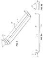
- FIG. 5 is a perspective view of a bracket according to a further aspect of the present invention.
- FIG. 5A is a side view of the bracket shown in FIG. 5 .
- FIG. 5B is an end view of a portion of the bracket shown in FIG. 5 showing a flange and a catch.
- FIG. 6 is a view similar to that of FIG. 3 including a plurality of brackets.
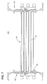
- FIG. 7 is a view similar to that of FIG. 6 including bus bar power conductors.
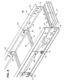
- FIG. 8 is an enlarged, partial perspective view of a power busway assembly shown in FIG. 7 .
- An embodiment of the present invention concerns a system and method for securing a power busway assembly that reduces the need for the use of fasteners, employs fewer components, yet still provides predictable consistent strength and high short circuit rating.
- FIG. 1 A prior art busway housing unit is shown generally at 10 in FIG. 1 .
- Housing unit 10 comprises a side plate or side piece 11 positioned opposite a complementary side plate or side piece 12.
- Side plates 11, 12 each are illustrated as having a U-shaped configuration, may include apertures (not shown) and comprise a non-ferrous metal, such as, an aluminum alloy that greatly increases the tensile strength of the aluminum without substantially deterring from the good electrical and thermal properties.
- the aluminum side plates 11, 12, which form busway housing 10 create a complete 360° high level ground path for ground faults and serves as a continuous bond between busway sections, fittings and bus plugs (not shown).
- Both aluminum side plates 11, 12 are provided with a top flange 13, 15 and a bottom flange 14, 16.
- Top flange 13 and bottom flange 14 extend perpendicularly from flat piece 8 on side plate 11.
- top flange 15 and bottom flange 16 extend perpendicularly from flat piece 9 on side plate 12.
- Rails 19, 20 extend perpendicularly from top flanges 13, 15.
- rails 20 extend perpendicularly from bottom flanges 14, 16 as indicated.
- One pair of rails 19 or 20 can provide hanger support connection means while the other pair of rails can provide ground stab connection means.
- Rails 19, 20 in addition to flanges 13-16 provide added structural support to busway housing unit 10 and increased surface area to side plates 11, 12 for improved thermal radiation to the surrounding air.
- Angulated slot 17 extends along one edge of top flange 13 on side plate 11 to receive a complementary angulated projection 18, which extends along top flange 15 on opposing side plate 12.
- a similar angulated slot 17' extends along bottom flange 16 of side plate 12 to receive a similar angulated projection 18', which extends along bottom flange 14 of side plate 11.
- Angulated slots 17, 17' and angulated projection 18, 18' provide interlocking means, which secure side plates 11 and 12 together.
- bus bars Three or four busway or bus bar power conductors 27, hereafter “bus bars", are attached to busway housing unit 10. Each bus bar 27 represents a separate phase of a three-phase power distribution system. Bus bars 27 are secured to busway housing unit 10 with a plurality of braces 30 (not shown).
- Brace 30 comprises cuffed segment 31, hooked end 32, and flanged end 33. Brace 30 is approximately 1.5" wide and 0.125" in thickness. The length of brace 30 may vary according to the dimensions of busway housing unit 10.
- brace 30 comprises a rigid and resilient material such as steel, which provides important mechanical properties such as strength and durability. These mechanical properties are desirable, for example, when a busway is exposed to dynamic and thermal stresses as a result of a short circuit. Because brace 30 is located outside of busway housing 10, brace 30 has no influence on the electrical properties of the busway.
- FIG. 3 illustrates a cross-section of an assembled busway housing unit 100 that includes a plurality of braces 30.
- Cuffed segment 31 is offset from flat segment 34 and accommodates the interlocking means of flanges 13-16. Specifically, angulated slots 17 and 17' fit directly inside cuffed segment 31, thus biasing the interlocking means of flanges 13-16.
- flat segment 34 sits directly on flanges 13 and 15.
- flat segment 34 sits directly on flanges 14 and 16.
- brace 30 may be interconnected with flanges 13, 15 and 14, 16 through slits 22 and 23.
- Hooked end 32 fits inside complementary slit 22, located on flanges 13 and 14.
- flanged end 33 fits inside complementary slit 23, located on flanges 15 and 16.
- Slit 22 on flange 13 is located directly parallel to slit 22 on flange 14.
- slit 23 on flange 15 is located directly parallel to slit 23 on flange 16.
- slits 22 and 23 are located along identical and regular intervals along the length of side plates 11 and 12, respectively, on approximately 12" centers. The area of each slit 22 is dimensioned to receive hooked end 32 of brace 30.
- each slit 23 is dimensioned to receive flanged end 33 of brace 30.
- hooked end 32 is inserted into slit 22. Then, a rotational force is applied to brace 30 until flanged end 33 is adjacent to complementary slit 23.
- An axial force perpendicular to side plates 11, 12 is applied to flanged end 33. The rotational force coupled with the axial force allows flanged end 33 to completely engage slit 23 and secures brace 30 into position.
- FIG. 4 shows a top view of a bracket 40 in accordance with another aspect of the invention.
- Bracket 40 comprises base 41 and a pair of flanges 44.
- Base 41 includes rib 42, which is a curved stiffening portion that runs longitudinally along the center of base 41.
- Flanges 44 extend perpendicularly from base 41 and comprise angled segment 43 and catch 45.
- Base 51 includes rib 52, which may be similar to rib 42.
- Flanges 54 also extend perpendicularly from base 51 and comprise angled segment 53 and catch 55.
- Brackets 40, 50 are approximately 2.5" wide and 0.1" in thickness.
- the length of brackets 40, 50 are equal and may vary according to the dimensions of busway housing unit 10. More particularly, the length of bases 41, 51 may vary according to lengths of flat pieces 9 and 8, respectively. Furthermore, the distance between catches 45 and 55 is equal.
- Brackets 40 and 50 are comprised of a rigid and resilient material such as steel, which provides important mechanical properties such as strength and durability. These properties are desirable, for example, when a busway is exposed to dynamic and thermal stresses as a result of a short circuit. Because brackets 40 and 50 are located outside of busway housing 10, brackets 40 and 50 have no influence on the electrical properties of the busway.
- FIG. 6 illustrates the assembled busway housing unit 100 of FIG. 3 including a plurality of brackets 40, 50.
- Brackets 40, 50 are dimensioned and configured to further secure busway system 100 by providing supplementary reinforcement to braces 30.
- Base 41 of bracket 40 runs traversely along flat piece 9 on side plate 12 ( FIG. 8 ).
- Rib 42 stiffens base 41 against flat piece 9 in order to prevent bracket 40 from lifting off side plate 12.
- Angled segments 43 curve away from side plate 12. Angled segments 43 distribute the forces from bracket 40 onto side plate 12 for a more secure busway system 100. In addition, angled segments 43 allow bracket 40 to apply an opposing force to flanges 15, 16 to reduce wear on flanges 15, 16 and brace 30.
- bracket 40 may be interconnected with each of flanges 15 and 16 through slits 23.
- Catch 45 hooks onto slits 23 discussed above.
- the width of slits 23 is at least equal to the width of bracket 40.
- the length between catches 45 is at least equal to the width of brace 30. This ensures that catches 45 and either flanged end 33 of brace 30 can both fit inside slot 23 at the same time.
- bracket 50 provides similar structure and functionality to side plate 11 that bracket 40 provides to side plate 12.
Landscapes
- Engineering & Computer Science (AREA)
- Architecture (AREA)
- Civil Engineering (AREA)
- Structural Engineering (AREA)
- Installation Of Bus-Bars (AREA)
Abstract
A power busway assembly includes a pair of opposing non-ferrous metal apertured side plates. The side plates have a U-shaped configuration and include a pair of top and bottom flanges that are joined by a flat piece. The power busway assembly further includes a means on one end of each of the flanges for interlocking the side plates together. The interlocking means intern has an angulated projection or an angulated slot. First rails extending from one of the pairs of flanges are also included that provide hanger support connection means. In addition, second rails extending from another one of the pairs of flanges are included that provide ground stab connection means. The power busway assembly further includes at least one brace that is interconnected with the flanges. The brace is dimensioned and configured to bias the interlocking means together. A method of securing a busway housing to busway power conductors is also presented.
Description
- The subject matter described herein relates generally to power busways and, more particularly, to securing a busway housing to busway power conductors.
- Power busways used within multi-phase electric power distribution systems generally consist of long, rectangular bars of copper or aluminum material. Each individual bar is electrically insulated to maintain electrical isolation between the individual phases as well as between the phase conductors and the neutral conductors. In accordance with electrical codes, a ground conductor must be associated within the busway power distribution system.
-
U.S. Patent No. 4,804,804 entitled "Thermally Efficient Power Busway Housing" describes a two-piece extruded aluminum alloy housing shaped to provide support and ground conduction facility to power busway conductors described above. The two-piece housing is attached together with snap-fit connectors along its top and bottom surfaces. The housing is attached to the busway power conductors by means of insulated bolts. - General Electric's Spectra™ Series Busway uses a unique double-insulated tie bolt to attach the aluminum housing to the busway power conductors. The tie bolts are inserted through the center of the busway providing predictable consistent strength and high short circuit rating.
- While it is effective to use insulated bolts to secure a busway assembly, a large number of bolts are necessary. Furthermore, using bolts complicates the art of busway construction as the bolts themselves may not come in contact with any part of the bus conductors since the busway housing is generally at ground potential. Therefore, it is desirable to provide an improved means for securing a busway assembly that eliminates the use of bolts, uses fewer components, but still provides predictable consistent strength and high short circuit rating.
- In accordance with an embodiment of the present invention, a power busway assembly comprises a pair of opposing non-ferrous metal apertured side plates. The side plates have a U-shaped configuration and intern comprise a pair of top and bottom flanges that are joined by a flat piece. The power busway assembly further comprises a means on one end of each of the flanges for interlocking the side plates together. The interlocking means intern comprises an angulated projection or an angulated slot. First rails extending from one of the pairs of flanges are also included that provide hanger support connection means. In addition, second rails extending from another one of the pairs of flanges are included that provide ground stab connection means. The power busway assembly further comprises at least one brace that is interconnected with the flanges. The brace is dimensioned and configured to bias the interlocking means together.
- In another embodiment of the invention, a method of securing a busway housing to busway power conductors comprises using a plurality of braces. The busway housing comprises a pair of opposing non-ferrous metal apertured side plates. The side plates have a U-shaped configuration and intern comprise a pair of top and bottom flanges that are joined by a flat piece. The top and bottom flanges comprise slits, and the plurality of braces comprises a hooked end and a flanged end. The method comprises inserting the hooked end into one of the slits, and rotating the brace until the flanged end is adjacent to another of the slits. The method further comprises providing an axial force to the flanged end, wherein the force is perpendicular to the side plates, and whereby the flanged end completely engages the another of the slits.
- The following detailed description is made with reference to the accompanying drawings, in which:
-
FIG. 1 is a perspective view of a busway housing unit for supporting the bus bar power conductors. -
FIG. 2 is a perspective view of a brace in accordance with one embodiment of the present invention. -
FIG. 2A is a bottom view of the brace shown inFIG. 2 . -
FIG. 2B is a side view of the brace shown inFIG. 2 . -
FIG. 3 is a cross-sectional view along line 3-3 inFIG. 1 of the busway housing unit ofFIG. 1 including a plurality of the braces ofFIG. 2 . -
FIG. 4 is a perspective view of a bracket according to another aspect of the present invention. -
FIG. 4A is a side view of the bracket shown inFIG. 4 . -
FIG. 4B is an end view of a portion of the bracket shown inFIG. 4 showing a flange and a catch. -
FIG. 5 is a perspective view of a bracket according to a further aspect of the present invention. -
FIG. 5A is a side view of the bracket shown inFIG. 5 . -
FIG. 5B is an end view of a portion of the bracket shown inFIG. 5 showing a flange and a catch. -
FIG. 6 is a view similar to that ofFIG. 3 including a plurality of brackets. -
FIG. 7 is a view similar to that ofFIG. 6 including bus bar power conductors. -
FIG. 8 is an enlarged, partial perspective view of a power busway assembly shown inFIG. 7 . - An embodiment of the present invention concerns a system and method for securing a power busway assembly that reduces the need for the use of fasteners, employs fewer components, yet still provides predictable consistent strength and high short circuit rating.
- A prior art busway housing unit is shown generally at 10 in
FIG. 1 .Housing unit 10 comprises a side plate orside piece 11 positioned opposite a complementary side plate orside piece 12.Side plates aluminum side plates busway housing 10, create a complete 360° high level ground path for ground faults and serves as a continuous bond between busway sections, fittings and bus plugs (not shown). - Both
aluminum side plates top flange bottom flange Top flange 13 andbottom flange 14 extend perpendicularly fromflat piece 8 onside plate 11. Similarly,top flange 15 andbottom flange 16 extend perpendicularly fromflat piece 9 onside plate 12. -
Side plates corresponding rails Rails 19 extend perpendicularly fromtop flanges rails 20 extend perpendicularly frombottom flanges rails Rails busway housing unit 10 and increased surface area toside plates -
Angulated slot 17 extends along one edge oftop flange 13 onside plate 11 to receive a complementaryangulated projection 18, which extends alongtop flange 15 on opposingside plate 12. A similar angulated slot 17' extends alongbottom flange 16 ofside plate 12 to receive a similar angulated projection 18', which extends alongbottom flange 14 ofside plate 11.Angulated slots 17, 17' and angulatedprojection 18, 18' provide interlocking means, which secureside plates - Three or four busway or bus
bar power conductors 27, hereafter "bus bars", are attached to buswayhousing unit 10. Eachbus bar 27 represents a separate phase of a three-phase power distribution system. Bus bars 27 are secured to buswayhousing unit 10 with a plurality of braces 30 (not shown). - Referring now to
FIG. 2 a top view of a brace in accordance with one embodiment of the present invention is shown generally at 30.Brace 30 comprises cuffedsegment 31, hookedend 32, andflanged end 33.Brace 30 is approximately 1.5" wide and 0.125" in thickness. The length ofbrace 30 may vary according to the dimensions ofbusway housing unit 10. - In one particular embodiment, brace 30 comprises a rigid and resilient material such as steel, which provides important mechanical properties such as strength and durability. These mechanical properties are desirable, for example, when a busway is exposed to dynamic and thermal stresses as a result of a short circuit. Because
brace 30 is located outside ofbusway housing 10,brace 30 has no influence on the electrical properties of the busway. -
FIG. 3 illustrates a cross-section of an assembledbusway housing unit 100 that includes a plurality ofbraces 30.Cuffed segment 31 is offset fromflat segment 34 and accommodates the interlocking means of flanges 13-16. Specifically, angulatedslots 17 and 17' fit directly inside cuffedsegment 31, thus biasing the interlocking means of flanges 13-16. When cuffedsegment 31 is in position directly on top of angulatedslot 17,flat segment 34 sits directly onflanges segment 31 is in position directly on top of angulated slot 17',flat segment 34 sits directly onflanges - Furthermore, brace 30 may be interconnected with
flanges slits Hooked end 32 fits insidecomplementary slit 22, located onflanges flanged end 33 fits insidecomplementary slit 23, located onflanges Slit 22 onflange 13 is located directly parallel to slit 22 onflange 14. Similarly, slit 23 onflange 15 is located directly parallel to slit 23 onflange 16. As seen inFIG. 8 , slits 22 and 23 are located along identical and regular intervals along the length ofside plates hooked end 32 ofbrace 30. Similarly, the area of each slit 23 is dimensioned to receiveflanged end 33 ofbrace 30.
Referring again toFIG. 3 , to securebrace 30, hookedend 32 is inserted intoslit 22.
Then, a rotational force is applied to brace 30 untilflanged end 33 is adjacent tocomplementary slit 23. An axial force perpendicular toside plates flanged end 33. The rotational force coupled with the axial force allowsflanged end 33 to completely engage slit 23 and securesbrace 30 into position. - In accordance with another feature of the present invention, a plurality of
brackets busway housing unit 100.FIG. 4 shows a top view of abracket 40 in accordance with another aspect of the invention.Bracket 40 comprisesbase 41 and a pair offlanges 44.Base 41 includesrib 42, which is a curved stiffening portion that runs longitudinally along the center ofbase 41.Flanges 44 extend perpendicularly frombase 41 and comprise angledsegment 43 and catch 45. - Similarly,
bracket 50, shown inFIG. 5 comprisesbase 51 and a pair offlanges 54.Base 51 includesrib 52, which may be similar torib 42.Flanges 54 also extend perpendicularly frombase 51 and comprise angledsegment 53 and catch 55. -
Brackets brackets busway housing unit 10. More particularly, the length ofbases flat pieces -
Brackets brackets busway housing 10,brackets -
FIG. 6 illustrates the assembledbusway housing unit 100 ofFIG. 3 including a plurality ofbrackets Brackets busway system 100 by providing supplementary reinforcement to braces 30.Base 41 ofbracket 40 runs traversely alongflat piece 9 on side plate 12 (FIG. 8 ).Rib 42 stiffensbase 41 againstflat piece 9 in order to preventbracket 40 from lifting offside plate 12. -
Angled segments 43 curve away fromside plate 12.Angled segments 43 distribute the forces frombracket 40 ontoside plate 12 for a moresecure busway system 100. In addition,angled segments 43 allowbracket 40 to apply an opposing force toflanges flanges brace 30. - Furthermore,
bracket 40 may be interconnected with each offlanges slits 23.Catch 45 hooks ontoslits 23 discussed above. As seen inFIG. 8 , the width ofslits 23 is at least equal to the width ofbracket 40. Furthermore, the length between catches 45 is at least equal to the width ofbrace 30. This ensures that catches 45 and eitherflanged end 33 ofbrace 30 can both fit insideslot 23 at the same time. - Referring again to
FIG. 6 ,bracket 50 provides similar structure and functionality toside plate 11 thatbracket 40 provides toside plate 12. - While the present invention has been described in connection with what are presently considered to be the most practical and preferred embodiments, it is to be understood that the present invention is not limited to these herein disclosed embodiments. Rather, the present invention is intended to cover all of the various modifications and equivalent arrangements included within the scope of the appended claims.
- Aspects of the present invention are defined in the following numbered clauses:
- 1. A power busway assembly comprising:
- a pair of opposing non-ferrous metal apertured side plates, each of the plates having a U-shaped configuration comprising a pair of top and bottom flanges joined by a flat piece;
- means on one end of each of the flanges for interlocking the side plates together, the interlocking means comprising an angulated projection or an angulated slot;
- first rails extending from one of the pairs of flanges, the first rails providing hanger support connection means;
- second rails extending from another one of the pairs of flanges, the second rails providing ground stab connection means; and
- at least one brace interconnected with the flanges and being dimensioned and configured to bias the interlocking means together.
- 2. The power busway assembly of clause 1, wherein the side plates are extruded.
- 3. The power busway assembly of clause 1, wherein the non-ferrous metal is selected from the group consisting of aluminum and copper.
- 4. The power busway assembly of clause 1, further comprising:
- slits located along identical and regular intervals along the side plates.
- 5. The power busway assembly of clause 4, wherein the at least one brace comprises a plurality of braces and wherein each is interconnected with the flanges through the slits.
- 6. The power busway assembly of clause 5, wherein the plurality of braces comprise a cuffed segment, a hooked end, and a flanged end.
- 7. The power busway assembly of clause 6, wherein the cuffed segment accommodates said interlocking means.
- 8. The power busway assembly of clause 1, wherein the braces are formed from a rigid and resilient material.
- 9. The power busway assembly of
clause 8, wherein the rigid and resilient material comprises steel. - 10. The power busway assembly of clause 4, further comprising:
- at least one bracket interconnected with the flanges and the at least one bracket being dimensioned and configured to reinforce a pair of opposing braces.
- 11. The power busway assembly of
clause 10, wherein the at least one bracket comprises a plurality of brackets and wherein each is interconnected with the flanges through the slits. - 12. The power busway assembly of
clause 11, wherein the plurality of brackets comprise a base and a pair of flanges. - 13. The power busway assembly of
clause 12,
wherein the base comprises a rib; and
wherein the pair of flanges comprise an angled segment and a catch. - 14. The power busway assembly of
clause 13,
wherein the rib stiffens said base against said flat piece; and
wherein the catch hooks onto the slits. - 15. The power busway assembly of
clause 11, wherein the plurality of brackets are formed from a rigid and resilient material. - 16. The power busway assembly of
clause 15, wherein the rigid and resilient material comprises steel. - 17. A method of securing a busway housing to busway power conductors using a plurality of braces, the busway housing comprising a pair of opposing non-ferrous metal apertured side plates, the plates having a U-shaped configuration comprising a pair of top and bottom flanges joined by a flat piece and comprising slits, the plurality of braces comprising a hooked end and a flanged end, the method comprising:
- inserting the hooked end into one of the slits;
- rotating the brace until the flanged end is adjacent to another of the slits;
- providing an axial force to the flanged end, wherein the force is perpendicular to the side plates whereby the flanged end completely engages the another of the slits.
- 18. The method of
clause 17, wherein the slits are located along identical and regular intervals along the side plates. - 19. The method of
clause 18, further comprising:- securing the plurality of braces along the identical and regular intervals.
- 20. The method of
clause 19, further comprising:- interconnecting a plurality of brackets to the flanges through the slits.
- 21. The method of
clause 20, further comprising:- securing the plurality of brackets along the identical and regular intervals.
Claims (10)
- A power busway assembly comprising:a pair of opposing non-ferrous metal apertured side plates, each of the plates having a U-shaped configuration comprising a pair of top and bottom flanges joined by a flat piece;means on one end of each of the flanges for interlocking the side plates together, the interlocking means comprising an angulated projection or an angulated slot;first rails extending from one of the pairs of flanges, the first rails providing hanger support connection means;second rails extending from another one of the pairs of flanges, the second rails providing ground stab connection means; andat least one brace interconnected with the flanges and being dimensioned and configured to bias the interlocking means together.
- The power busway assembly of claim 1, wherein the side plates are extruded.
- The power busway assembly of claim 1 or claim 2, wherein the non-ferrous metal is selected from the group consisting of aluminum and copper.
- The power busway assembly of any one of the preceding claims, further comprising:slits located along identical and regular intervals along the side plates.
- The power busway assembly of claim 4, wherein the at least one brace comprises a plurality of braces and wherein each of the plurality of braces is interconnected with the flanges through the slits.
- The power busway assembly of any one of the preceding claims, wherein each of the plurality of braces comprises a cuffed segment, the cuffed segment accommodating the interlocking means.
- The power busway assembly of any one of the preceding claims, further comprising:at least one bracket interconnected with the flanges, the at least one bracket being dimensioned and configured to reinforce a pair of opposing braces.
- The power busway assembly of claim 7, wherein the at least one bracket comprises a plurality of brackets and wherein each of the plurality of brackets is interconnected with the flanges through the slits.
- The power busway assembly of claim 8, wherein the each of the plurality of brackets comprises a rib, the rib stiffening each of the plurality of brackets to the flat piece.
- A method of securing a busway housing to busway power conductors using a plurality of braces, the busway housing comprising a pair of opposing non-ferrous metal apertured side plates, the plates having a U-shaped configuration comprising a pair of top and bottom flanges joined by a flat piece and comprising slits, the plurality of braces comprising a hooked end and a flanged end, the method comprising:inserting the hooked end into one of the slits;rotating the brace until the flanged end is adjacent to another of the slits;providing an axial force to the flanged end, wherein the force is perpendicular to the side plates whereby the flanged end completely engages the another of the slits.
Applications Claiming Priority (1)
| Application Number | Priority Date | Filing Date | Title |
|---|---|---|---|
| US11/950,940 US20090145625A1 (en) | 2007-12-05 | 2007-12-05 | System and Method for Securing a Busway Housing to Busway Power Conductors |
Publications (1)
| Publication Number | Publication Date |
|---|---|
| EP2068412A2 true EP2068412A2 (en) | 2009-06-10 |
Family
ID=40373718
Family Applications (1)
| Application Number | Title | Priority Date | Filing Date |
|---|---|---|---|
| EP08170070A Withdrawn EP2068412A2 (en) | 2007-12-05 | 2008-11-27 | System and method for securing a busway housing to busway power conductors |
Country Status (8)
| Country | Link |
|---|---|
| US (1) | US20090145625A1 (en) |
| EP (1) | EP2068412A2 (en) |
| JP (1) | JP2009142148A (en) |
| KR (1) | KR20090059057A (en) |
| CN (1) | CN101453107A (en) |
| AU (1) | AU2008246263A1 (en) |
| CA (1) | CA2644248A1 (en) |
| MX (1) | MX2008015482A (en) |
Cited By (2)
| Publication number | Priority date | Publication date | Assignee | Title |
|---|---|---|---|---|
| US8576082B2 (en) | 2010-07-15 | 2013-11-05 | Jones Group Forensic Engineers | Busway joint parameter detection system |
| EP3151353A1 (en) * | 2015-09-29 | 2017-04-05 | EAE Elektrik Asansör Endüstrisi Insaat Sanayi ve Ticaret Anonim Sirketi | A click-fit casing for a busbar |
Families Citing this family (17)
| Publication number | Priority date | Publication date | Assignee | Title |
|---|---|---|---|---|
| US7819676B1 (en) * | 2009-11-12 | 2010-10-26 | Power Distribution Inc. | Electrical power distribution system |
| KR100986678B1 (en) * | 2009-11-30 | 2010-10-08 | 주식회사 광명전기 | Plug in bus duct |
| US8847088B2 (en) | 2011-09-22 | 2014-09-30 | General Electric Company | Cover mounted handle operating mechanism with integrated interlock assembly for a busplug enclosure |
| KR101225249B1 (en) * | 2011-10-17 | 2013-01-22 | 대한전선 주식회사 | Duct structure for bus duct |
| JP6082547B2 (en) * | 2012-09-04 | 2017-02-15 | 株式会社アテックス | Busbar insert resin molded product manufacturing method |
| CN102868127A (en) * | 2012-09-11 | 2013-01-09 | 江苏华强电力设备有限公司 | Novel bus groove side plate |
| US9281674B2 (en) | 2012-11-01 | 2016-03-08 | Schneider Electric USA, Inc. | Method of busway construction |
| CN104269798A (en) * | 2014-09-20 | 2015-01-07 | 常州市武进庙桥南方锻造有限公司 | Anti-theft type bus duct |
| CN107785844A (en) * | 2016-08-27 | 2018-03-09 | 江苏德驰电气有限公司 | A kind of high current air insulation bus-slot |
| CN107546696A (en) * | 2017-10-18 | 2018-01-05 | 江苏瑞仁汽车部件有限公司 | Concentration bus duct |
| CN108167529B (en) * | 2018-02-05 | 2023-12-19 | 徐工集团工程机械股份有限公司 | Multifunctional pipe line suspension fixing system for engineering machinery |
| CN111490509A (en) * | 2020-04-28 | 2020-08-04 | 镇江市美盛母线有限公司 | A new type of dense busway shell structure |
| CN111490508A (en) * | 2020-04-28 | 2020-08-04 | 镇江市美盛母线有限公司 | A convenient installation intensive busway |
| CN112234556B (en) * | 2020-11-20 | 2022-02-08 | 吉林大洋电气科技有限公司 | Bus duct fixing equipment for power bus processing |
| US11824336B2 (en) * | 2021-10-21 | 2023-11-21 | Siemens Industry, Inc. | Outdoor busway system having protected conductor sections |
| CN114725867B (en) * | 2022-03-24 | 2024-09-20 | 国网浙江省电力有限公司桐庐县供电公司 | Bus duct for easy assembly |
| CN118867925A (en) * | 2024-09-23 | 2024-10-29 | 浙江桥架母线有限公司 | A kind of anti-corrosion protection device for bus duct |
Citations (1)
| Publication number | Priority date | Publication date | Assignee | Title |
|---|---|---|---|---|
| US4804804A (en) | 1987-11-19 | 1989-02-14 | General Electric Company | Thermally efficient power busway housing |
Family Cites Families (2)
| Publication number | Priority date | Publication date | Assignee | Title |
|---|---|---|---|---|
| US4950841A (en) * | 1989-05-30 | 1990-08-21 | General Electric Company | Thermally efficient splice joint for electrical distribution busway |
| US6180885B1 (en) * | 1997-01-17 | 2001-01-30 | General Electric Company | Weatherproofing busway systems |
-
2007
- 2007-12-05 US US11/950,940 patent/US20090145625A1/en not_active Abandoned
-
2008
- 2008-11-20 AU AU2008246263A patent/AU2008246263A1/en not_active Abandoned
- 2008-11-20 CA CA002644248A patent/CA2644248A1/en not_active Abandoned
- 2008-11-27 EP EP08170070A patent/EP2068412A2/en not_active Withdrawn
- 2008-12-02 JP JP2008306922A patent/JP2009142148A/en not_active Withdrawn
- 2008-12-04 MX MX2008015482A patent/MX2008015482A/en not_active Application Discontinuation
- 2008-12-04 KR KR1020080122525A patent/KR20090059057A/en not_active Withdrawn
- 2008-12-05 CN CNA2008101798121A patent/CN101453107A/en active Pending
Patent Citations (1)
| Publication number | Priority date | Publication date | Assignee | Title |
|---|---|---|---|---|
| US4804804A (en) | 1987-11-19 | 1989-02-14 | General Electric Company | Thermally efficient power busway housing |
Cited By (2)
| Publication number | Priority date | Publication date | Assignee | Title |
|---|---|---|---|---|
| US8576082B2 (en) | 2010-07-15 | 2013-11-05 | Jones Group Forensic Engineers | Busway joint parameter detection system |
| EP3151353A1 (en) * | 2015-09-29 | 2017-04-05 | EAE Elektrik Asansör Endüstrisi Insaat Sanayi ve Ticaret Anonim Sirketi | A click-fit casing for a busbar |
Also Published As
| Publication number | Publication date |
|---|---|
| KR20090059057A (en) | 2009-06-10 |
| AU2008246263A1 (en) | 2009-07-02 |
| MX2008015482A (en) | 2009-11-26 |
| JP2009142148A (en) | 2009-06-25 |
| US20090145625A1 (en) | 2009-06-11 |
| CA2644248A1 (en) | 2009-06-05 |
| CN101453107A (en) | 2009-06-10 |
Similar Documents
| Publication | Publication Date | Title |
|---|---|---|
| EP2068412A2 (en) | System and method for securing a busway housing to busway power conductors | |
| US4804804A (en) | Thermally efficient power busway housing | |
| CN107017472B (en) | Power Bus Channel Connectors with Self-Adjusting Brackets | |
| US9590405B1 (en) | Busway joint coupling having an adjustable assembly for joining two busway sections | |
| US6039584A (en) | Electrical power distribution system | |
| CN106953217B (en) | Power Busway Connectors with Laminated Support System | |
| US6781818B2 (en) | Bus brace comb assembly | |
| CN107017536B (en) | Adjustable Power Busway Connectors with Fork Busbars | |
| US8163998B2 (en) | Electrical busway flange end stub | |
| US4886468A (en) | Insulated electrical power distribution busway tabs | |
| US20170201081A1 (en) | Electrical busway joint with external vise braces | |
| EP2806517B1 (en) | Bus bar for electrical power distribution | |
| AU584362B2 (en) | Electrical distribution system with an improved housing | |
| US5828006A (en) | Busway system with wedge brace supports | |
| US10522991B2 (en) | Compact busway for low and medium voltage | |
| WO2017147256A1 (en) | Splice plate assembly for cable tray | |
| CN103682998A (en) | Modular insulator for busbar support and method of assembling | |
| CN101485058B (en) | Insulating element for busbars and insulating and supporting device for busbars comprising this element | |
| MX2014002516A (en) | System and method for providing discrete access points in an electrical busway. | |
| JPS59501441A (en) | Rail insulator for fixing conductor rails on rail supports | |
| CN1879281B (en) | Long stator comprising a ground conductor and maglev railway that is equipped with said stator | |
| US20060121796A1 (en) | Electric phase bus bar | |
| EP0319483A2 (en) | Modular low-voltage electrical panel for modular electrical apparatus | |
| EP3866287B1 (en) | Supporting insulator for conductor rails of a switchboard | |
| CA1316996C (en) | Insulated electrical power distribution busway tabs |
Legal Events
| Date | Code | Title | Description |
|---|---|---|---|
| PUAI | Public reference made under article 153(3) epc to a published international application that has entered the european phase |
Free format text: ORIGINAL CODE: 0009012 |
|
| AK | Designated contracting states |
Kind code of ref document: A2 Designated state(s): AT BE BG CH CY CZ DE DK EE ES FI FR GB GR HR HU IE IS IT LI LT LU LV MC MT NL NO PL PT RO SE SI SK TR |
|
| AX | Request for extension of the european patent |
Extension state: AL BA MK RS |
|
| STAA | Information on the status of an ep patent application or granted ep patent |
Free format text: STATUS: THE APPLICATION IS DEEMED TO BE WITHDRAWN |
|
| 18D | Application deemed to be withdrawn |
Effective date: 20110531 |