EP2068402B1 - A device for measuring the current of a battery on board of a motor-vehicle and a method for assembling the device - Google Patents
A device for measuring the current of a battery on board of a motor-vehicle and a method for assembling the device Download PDFInfo
- Publication number
- EP2068402B1 EP2068402B1 EP07425685A EP07425685A EP2068402B1 EP 2068402 B1 EP2068402 B1 EP 2068402B1 EP 07425685 A EP07425685 A EP 07425685A EP 07425685 A EP07425685 A EP 07425685A EP 2068402 B1 EP2068402 B1 EP 2068402B1
- Authority
- EP
- European Patent Office
- Prior art keywords
- plate
- bar
- groove
- terminal
- shunt
- Prior art date
- Legal status (The legal status is an assumption and is not a legal conclusion. Google has not performed a legal analysis and makes no representation as to the accuracy of the status listed.)
- Not-in-force
Links
- 238000000034 method Methods 0.000 title claims description 10
- 238000003466 welding Methods 0.000 claims abstract description 8
- 239000004020 conductor Substances 0.000 claims abstract description 6
- 239000000843 powder Substances 0.000 claims description 2
- 239000000463 material Substances 0.000 description 7
- RYGMFSIKBFXOCR-UHFFFAOYSA-N Copper Chemical compound [Cu] RYGMFSIKBFXOCR-UHFFFAOYSA-N 0.000 description 6
- 229910000896 Manganin Inorganic materials 0.000 description 6
- 239000010949 copper Substances 0.000 description 6
- 229910052802 copper Inorganic materials 0.000 description 6
- 238000005259 measurement Methods 0.000 description 5
- 238000001514 detection method Methods 0.000 description 2
- 239000011810 insulating material Substances 0.000 description 2
- 229910001369 Brass Inorganic materials 0.000 description 1
- 239000010951 brass Substances 0.000 description 1
- 238000006243 chemical reaction Methods 0.000 description 1
- 230000003750 conditioning effect Effects 0.000 description 1
- 238000001816 cooling Methods 0.000 description 1
- 230000001419 dependent effect Effects 0.000 description 1
- 238000010438 heat treatment Methods 0.000 description 1
- 238000003780 insertion Methods 0.000 description 1
- 230000037431 insertion Effects 0.000 description 1
- 238000003754 machining Methods 0.000 description 1
- 230000035945 sensitivity Effects 0.000 description 1
Images


Classifications
-
- H—ELECTRICITY
- H01—ELECTRIC ELEMENTS
- H01R—ELECTRICALLY-CONDUCTIVE CONNECTIONS; STRUCTURAL ASSOCIATIONS OF A PLURALITY OF MUTUALLY-INSULATED ELECTRICAL CONNECTING ELEMENTS; COUPLING DEVICES; CURRENT COLLECTORS
- H01R11/00—Individual connecting elements providing two or more spaced connecting locations for conductive members which are, or may be, thereby interconnected, e.g. end pieces for wires or cables supported by the wire or cable and having means for facilitating electrical connection to some other wire, terminal, or conductive member, blocks of binding posts
- H01R11/11—End pieces or tapping pieces for wires, supported by the wire and for facilitating electrical connection to some other wire, terminal or conductive member
- H01R11/28—End pieces consisting of a ferrule or sleeve
- H01R11/281—End pieces consisting of a ferrule or sleeve for connections to batteries
- H01R11/287—Intermediate parts between battery post and cable end piece
-
- H—ELECTRICITY
- H01—ELECTRIC ELEMENTS
- H01M—PROCESSES OR MEANS, e.g. BATTERIES, FOR THE DIRECT CONVERSION OF CHEMICAL ENERGY INTO ELECTRICAL ENERGY
- H01M10/00—Secondary cells; Manufacture thereof
- H01M10/42—Methods or arrangements for servicing or maintenance of secondary cells or secondary half-cells
- H01M10/48—Accumulators combined with arrangements for measuring, testing or indicating the condition of cells, e.g. the level or density of the electrolyte
-
- G—PHYSICS
- G01—MEASURING; TESTING
- G01R—MEASURING ELECTRIC VARIABLES; MEASURING MAGNETIC VARIABLES
- G01R1/00—Details of instruments or arrangements of the types included in groups G01R5/00 - G01R13/00 and G01R31/00
- G01R1/20—Modifications of basic electric elements for use in electric measuring instruments; Structural combinations of such elements with such instruments
- G01R1/203—Resistors used for electric measuring, e.g. decade resistors standards, resistors for comparators, series resistors, shunts
-
- G—PHYSICS
- G01—MEASURING; TESTING
- G01R—MEASURING ELECTRIC VARIABLES; MEASURING MAGNETIC VARIABLES
- G01R31/00—Arrangements for testing electric properties; Arrangements for locating electric faults; Arrangements for electrical testing characterised by what is being tested not provided for elsewhere
- G01R31/36—Arrangements for testing, measuring or monitoring the electrical condition of accumulators or electric batteries, e.g. capacity or state of charge [SoC]
- G01R31/364—Battery terminal connectors with integrated measuring arrangements
-
- G—PHYSICS
- G01—MEASURING; TESTING
- G01R—MEASURING ELECTRIC VARIABLES; MEASURING MAGNETIC VARIABLES
- G01R31/00—Arrangements for testing electric properties; Arrangements for locating electric faults; Arrangements for electrical testing characterised by what is being tested not provided for elsewhere
- G01R31/36—Arrangements for testing, measuring or monitoring the electrical condition of accumulators or electric batteries, e.g. capacity or state of charge [SoC]
- G01R31/382—Arrangements for monitoring battery or accumulator variables, e.g. SoC
-
- H—ELECTRICITY
- H01—ELECTRIC ELEMENTS
- H01M—PROCESSES OR MEANS, e.g. BATTERIES, FOR THE DIRECT CONVERSION OF CHEMICAL ENERGY INTO ELECTRICAL ENERGY
- H01M2200/00—Safety devices for primary or secondary batteries
- H01M2200/10—Temperature sensitive devices
- H01M2200/108—Normal resistors
-
- Y—GENERAL TAGGING OF NEW TECHNOLOGICAL DEVELOPMENTS; GENERAL TAGGING OF CROSS-SECTIONAL TECHNOLOGIES SPANNING OVER SEVERAL SECTIONS OF THE IPC; TECHNICAL SUBJECTS COVERED BY FORMER USPC CROSS-REFERENCE ART COLLECTIONS [XRACs] AND DIGESTS
- Y02—TECHNOLOGIES OR APPLICATIONS FOR MITIGATION OR ADAPTATION AGAINST CLIMATE CHANGE
- Y02E—REDUCTION OF GREENHOUSE GAS [GHG] EMISSIONS, RELATED TO ENERGY GENERATION, TRANSMISSION OR DISTRIBUTION
- Y02E60/00—Enabling technologies; Technologies with a potential or indirect contribution to GHG emissions mitigation
- Y02E60/10—Energy storage using batteries
Definitions
- the present invention relates to devices for measuring the current of a battery on board a motor vehicle, of the type indicated in the precharacterizing portion of claim 1.
- a device of this type is shown in FR-A-2 866 158 .
- a battery current sensor in form of a cylindrical bar having its opposite ends fitted within connecting sleeves is known from WO-A-2006/119953 .
- the general technical problem underlying the use of devices of the type referred to above is to measure the state of charge (SOC) of a battery on board a motor vehicle, as well as to assess the state of health (SOH) thereof and the state of function (SOF), i.e., how far it is able to perform its task properly, in particular starting of the engine of the motor vehicle.
- SOC state of charge
- SOF state of function
- Said measurements imply the measurement of the voltage across the poles of the battery, the temperature, and the current supplied and absorbed by the battery. Determination of the voltage does not involve any particular problems. Determination of the temperature is carried out in any suitable way, for example using thermocouples or thermistors or detection circuits. The problem of the measurement of the current does not, instead, have an immediate solution, for the reasons given hereinafter.
- the range of variability of the battery current is extremely wide, measurement thereof being required in various steps of operation of the vehicle.
- the high current requirement imposes the need to use a very low resistance, typically of the order of 100 ⁇ so as to contain the dissipation of power (225 W for a few seconds, in the example considered).
- the use of such a low resistive value poses problems of signal-to-noise ratio on the voltage values detected across the resistance, as well as of sensitivity of the electronics for conditioning and conversion of the signal.
- a noise level of 10 mA pp on a resistance of 100 ⁇ is equivalent to a voltage signal of 1 ⁇ V.
- the solution adopted in more conventional devices consists in making the shunt functioning as sensing element with a material the electrical resistance of which presents an extremely small variation in the required temperature range, such as for example Manganin.
- the present invention relates to devices for measuring the battery current both of the type using a shunt made of a material such as Manganin, the resistivity of which is relatively indifferent to temperature variations, and of the type in which the shunt is made of a material the resistivity of which varies significantly as the temperature varies and for which there is hence provided a circuit for compensation of the detected current value as the temperature varies.
- the purpose of the invention is to provide a device of this type that will present a structure that is extremely simple, light, and easy and fast to assemble.
- the subject of the invention is a device as specified in the annexed Claim 1 and an assembly method as specified in Claim 8. Further characteristics of some advantageous embodiments of the invention form the subject of the annexed dependent claims.
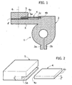
- the number 1 indicates as a whole a terminal of a motor-vehicle battery comprising a body 2, in itself of a known type, made for example of brass, having two elastically deformable terminal arms 2a, 2b for gripping together a terminal of the battery, and a base plate 3.
- the reference number 4 designates as a whole an element for detecting the battery current, or shunt, constituted by a plate, which in the example illustrated is made of a material having a resistivity that is substantially indifferent to temperature variations, such as for example Manganin.
- the plate 4 constituting the shunt has an end 4a connected directly to a bar 5, made of copper, which is in turn designed to be connected to a conductive cable (not illustrated).
- the copper bar 5 is fixed to the base portion 3 of the terminal 2 by means of screws (visible in Figure 1 is just one axis 6 of one of said screws).
- set between the bar 5 and the portion 3 of the terminal 2 is a layer of insulating material 8.
- the shunt 4 is designed to be connected to an electronic detection unit (not illustrated), designed to gather and process the data regarding the voltage across the shunt 4, at the temperature and at the value of the current that traverses it.
- the first end 4a of the plate constituting the shunt 4 is fixed within a groove 5a of the bar 5.
- a second end 4b of the plate 4 is fixed within a groove 2c of the body 2 of the terminal 1.
- a fundamental characteristic of the device and of the method according to the invention lies in the fact that the first end 4a of the plate 4 constituting the shunt is connected directly to the bar 5 only by means of a mechanical connection, without welding.
- the end 4a of the shunt 4 is fixed with an interference fit within the groove 5a.
- the groove 5a is made in the bar 5 with a height a ( Figure 2 ) that is slightly smaller than the height b of the plate 4 constituting the shunt.
- the aforesaid interference fit is obtained by inserting the plate 4 within the groove 5a after having obtained an increase in the height of the groove 5a by means of a step of heating of the bar 5 so as to clamp the plate 4 within the groove following upon subsequent cooling of the bar.
- a further advantage can be obtained by making the plate 4 with a material having a coefficient of thermal expansion higher than that of the material constituting the bar 5, in such a way that the interference between the plate 4 and the groove 5a of the bar 5 increases as the temperature rises during use of the motor vehicle. Said increase in temperature may be considerable above all in the case where the battery of the motor vehicle is housed, as is frequently the case, in the engine compartment.
- the plate 4 a material, such as for example Manganin, that has a coefficient of thermal expansion that is not higher than that of the copper constituting the bar 5 (Manganin has a coefficient of thermal expansion of 14 ⁇ 10 -6 K -1 , whilst the coefficient of copper is 16.5 ⁇ 10 -6 K -1 ).
- the percentage of thermal expansion of copper at 1000°C is 16.5.10 -3 , i.e., approximately 1.65%.
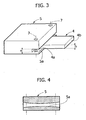
- Figures 3 and 4 illustrate an alternative solution, not forming part of the invention, in which the end 4a of the plate 4 constituting the shunt is once again received within a groove 5a of the bar 5, but the assembly is not by interference fit, the height b of the plate 4 being slightly smaller than the height a of the groove 5a.
- the end 4a is gripped within the groove by permanent deformation of the two opposed faces of the groove against one another. Said deformation can be obtained, for example, by means of screws inserted along the axes designated by 7. Illustrated with proportions exaggerated for reasons of clarity in Figure 4 is a particular embodiment of the two opposed faces of the groove 5a designed to optimize the connection between the bar 5 and the plate 4.
- Figures 5, 6 illustrate a further variant, not forming part of the invention, in which the end 4a of the plate 4 constituting the shunt is gripped between the bar 5 and an auxiliary element 8 in the form of a plane plate, made of conductive or insulating material, according to the need.
- the auxiliary plate 8 is flat and co-operates with a steplike cavity 9 made in the bar 5 to define the groove that receives the plate 4.
- the height of the steplike cavity 9, designated by a is slightly smaller than the height b of the plate 4, in such a way that gripping of the auxiliary plate 8 to the bar 5, which is obtained for example by means of one or more screws of axis 10, causes gripping of the plate 4 between the aforesaid elements.
- Figure 6 illustrates a variant in which the steplike cavity, designated by 11, is made in the auxiliary plate 8, whilst the bar 5 has a plane surface co-operating with the cavity 11 to define the groove that receives the plate 4.
- the end 4b of the plate 4 that is received within the groove 2c of the body 2 of the terminal 1 is also preferably connected directly to the terminal by means of a simple mechanical fit, without welding. Said fit can be obtained by means of simple interference or else, more conveniently, with any of the techniques described above in relation to the end 4a of the plate 4 with reference to Figures 2 , 3 , 4 , 5 and 6 .
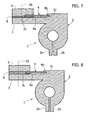
- the plate 4 has, at its first end 4a, an inclined head surface 4c, which co-operates with a corresponding inclined surface of the steplike cavity 9 of the bar 5.
- the end 4a of the plate 4 is gripped between the bar 5 and an auxiliary plate 8, by means of screws of axis 10 that grip said elements to the base portion 3 of the body of the terminal.
- the plate 5 (which is illustrated in said figure in a condition prior to execution of gripping) is pressed at the bottom downwards, against the auxiliary plate 8 and the base portion 3 of the terminal, by means of the screws of axis 10.
- Said downward movement causes, as a consequence of the fitting of the inclined surfaces, not only gripping of the end 4a of the plate 4 between the bar 5 and the auxiliary plate 8, but also a thrust towards the right (as viewed in the figure) of the plate 4, which causes a forcing of the end 4b within the groove 2c, with an interference fit.
- Figure 8 illustrates a solution similar to that of Figure 7 , which differs from the latter only in that therein, in a way similar to what is illustrated in Figure 6 , the groove that receives the end 4a of the plate 4 is made between a plane surface of the bar 5 and a steplike cavity of the auxiliary plate 8. Also in this case, as in the case of Figure 7 , the plate 4 has an inclined head surface 4c, which co-operates with a corresponding inclined surface of the auxiliary plate 8.
- the ensemble is illustrated in a condition prior to gripping of the bar 5 against the auxiliary plate 8 and the base portion 3 in such a way as to obtain, in addition to gripping of the end 4a between the bar 5 and the auxiliary plate 8, also a thrust towards the right (as viewed in the figure) of the plate 8, which increases forcing of the end 4b within the groove 2c.
- Figure 9 is a view corresponding to that of Figure 8 , which differs from the latter in so far as the auxiliary plate 8 does not extend underneath the plate 4 constituting the shunt, the space that separates the plate 4 from the portion 3 being filled with a layer 11 of thermally conductive material.
- the layer 11 can on the other hand be provided also in the embodiments represented in Figures 1 , 7 and 8 .
- conductive paste or powder in a position corresponding to the connection of one or both of the ends 4a, 4b of the plate 4 constituting the shunt.
Landscapes
- Engineering & Computer Science (AREA)
- Manufacturing & Machinery (AREA)
- Chemical & Material Sciences (AREA)
- Chemical Kinetics & Catalysis (AREA)
- Electrochemistry (AREA)
- General Chemical & Material Sciences (AREA)
- Physics & Mathematics (AREA)
- General Physics & Mathematics (AREA)
- Connection Of Batteries Or Terminals (AREA)
- Measuring Instrument Details And Bridges, And Automatic Balancing Devices (AREA)
- Automobile Manufacture Line, Endless Track Vehicle, Trailer (AREA)
Abstract
Description
- The present invention relates to devices for measuring the current of a battery on board a motor vehicle, of the type indicated in the precharacterizing portion of
claim 1. A device of this type is shown inFR-A-2 866 158 WO-A-2006/119953 . - The general technical problem underlying the use of devices of the type referred to above is to measure the state of charge (SOC) of a battery on board a motor vehicle, as well as to assess the state of health (SOH) thereof and the state of function (SOF), i.e., how far it is able to perform its task properly, in particular starting of the engine of the motor vehicle.
- Said measurements imply the measurement of the voltage across the poles of the battery, the temperature, and the current supplied and absorbed by the battery. Determination of the voltage does not involve any particular problems. Determination of the temperature is carried out in any suitable way, for example using thermocouples or thermistors or detection circuits. The problem of the measurement of the current does not, instead, have an immediate solution, for the reasons given hereinafter.
- The range of variability of the battery current is extremely wide, measurement thereof being required in various steps of operation of the vehicle. There may, for example, be required a measurement of a maximum of 1 A with an accepted noise level of 10 mApp (for example, with the ignition key in the ON position and the engine turned off) up to 1,500 A, during starting of the engine. The high current requirement imposes the need to use a very low resistance, typically of the order of 100 µΩ so as to contain the dissipation of power (225 W for a few seconds, in the example considered). On the other hand, the use of such a low resistive value poses problems of signal-to-noise ratio on the voltage values detected across the resistance, as well as of sensitivity of the electronics for conditioning and conversion of the signal. By way of example, a noise level of 10 mApp on a resistance of 100 µΩ is equivalent to a voltage signal of 1µV.
- Added to the aforesaid problems is the need of the value detected to be independent of the temperature, which is subject to wide variations, in particular in the (usual) case where the battery is housed in the engine compartment of the motor vehicle. The solution adopted in more conventional devices consists in making the shunt functioning as sensing element with a material the electrical resistance of which presents an extremely small variation in the required temperature range, such as for example Manganin.
- Illustrated in the document No.
DE 10 2004 042 719 A1EP 07 425 603.3 - The present invention relates to devices for measuring the battery current both of the type using a shunt made of a material such as Manganin, the resistivity of which is relatively indifferent to temperature variations, and of the type in which the shunt is made of a material the resistivity of which varies significantly as the temperature varies and for which there is hence provided a circuit for compensation of the detected current value as the temperature varies.
- The purpose of the invention is to provide a device of this type that will present a structure that is extremely simple, light, and easy and fast to assemble.
- With a view to achieving said purpose, the subject of the invention is a device as specified in the
annexed Claim 1 and an assembly method as specified inClaim 8. Further characteristics of some advantageous embodiments of the invention form the subject of the annexed dependent claims. - The invention will now be described with reference to the annexed plates of drawings, which are provided purely by way of non-limiting example and in which:
-
Figure 1 is a schematic cross-sectional view of a device according to a first embodiment which does not form part of the invention; and -
Figures 2-6 illustrate different embodiments not forming part of the invention, and -
Figures 7-10 illustrate different embodiments of the device and of the method according to the invention. - With reference to
Figure 1 , thenumber 1 indicates as a whole a terminal of a motor-vehicle battery comprising abody 2, in itself of a known type, made for example of brass, having two elastically deformableterminal arms base plate 3. Thereference number 4 designates as a whole an element for detecting the battery current, or shunt, constituted by a plate, which in the example illustrated is made of a material having a resistivity that is substantially indifferent to temperature variations, such as for example Manganin. Theplate 4 constituting the shunt has anend 4a connected directly to abar 5, made of copper, which is in turn designed to be connected to a conductive cable (not illustrated). Thecopper bar 5 is fixed to thebase portion 3 of theterminal 2 by means of screws (visible inFigure 1 is just one axis 6 of one of said screws). In the case of the example illustrated, set between thebar 5 and theportion 3 of theterminal 2 is a layer ofinsulating material 8. - The
shunt 4 is designed to be connected to an electronic detection unit (not illustrated), designed to gather and process the data regarding the voltage across theshunt 4, at the temperature and at the value of the current that traverses it. - In the case of the example illustrated in
Figure 1 , thefirst end 4a of the plate constituting theshunt 4 is fixed within agroove 5a of thebar 5. Likewise, asecond end 4b of theplate 4 is fixed within agroove 2c of thebody 2 of theterminal 1. - A fundamental characteristic of the device and of the method according to the invention lies in the fact that the
first end 4a of theplate 4 constituting the shunt is connected directly to thebar 5 only by means of a mechanical connection, without welding. According to a first embodiment not forming part of the invention, illustrated inFigure 2 , theend 4a of theshunt 4 is fixed with an interference fit within thegroove 5a. This means that thegroove 5a is made in thebar 5 with a height a (Figure 2 ) that is slightly smaller than the height b of theplate 4 constituting the shunt. - In one example of embodiment, not forming part of the invention, the aforesaid interference fit is obtained by inserting the
plate 4 within thegroove 5a after having obtained an increase in the height of thegroove 5a by means of a step of heating of thebar 5 so as to clamp theplate 4 within the groove following upon subsequent cooling of the bar. - In the case of said embodiment, a further advantage can be obtained by making the
plate 4 with a material having a coefficient of thermal expansion higher than that of the material constituting thebar 5, in such a way that the interference between theplate 4 and thegroove 5a of thebar 5 increases as the temperature rises during use of the motor vehicle. Said increase in temperature may be considerable above all in the case
where the battery of the motor vehicle is housed, as is frequently the case, in the engine compartment. - It should be pointed out, however, that it is altogether possible, to use for the
plate 4 a material, such as for example Manganin, that has a coefficient of thermal expansion that is not higher than that of the copper constituting the bar 5 (Manganin has a coefficient of thermal expansion of 14·10-6K-1, whilst the coefficient of copper is 16.5·10-6K-1). The percentage of thermal expansion of copper at 1000°C is 16.5.10-3, i.e., approximately 1.65%. This means that, if thegroove 5a has a height a of the order of a millimetre, the expansion is of the order of one hundredth of a millimetre, a value that is compatible with the precision of the machining operations currently performed and enables in any case a guarantee of the stability of the connection, notwithstanding the lower expansion of the Manganin constituting theplate 4. -
Figures 3 and 4 illustrate an alternative solution, not forming part of the invention, in which theend 4a of theplate 4 constituting the shunt is once again received within agroove 5a of thebar 5, but the assembly is not by interference fit, the height b of theplate 4 being slightly smaller than the height a of thegroove 5a. In this case, subsequent to insertion of theplate 4 within thegroove 5a, theend 4a is gripped within the groove by permanent deformation of the two opposed faces of the groove against one another. Said deformation can be obtained, for example, by means of screws inserted along the axes designated by 7. Illustrated with proportions exaggerated for reasons of clarity inFigure 4 is a particular embodiment of the two opposed faces of thegroove 5a designed to optimize the connection between thebar 5 and theplate 4. -
Figures 5, 6 illustrate a further variant, not forming part of the invention, in which theend 4a of theplate 4 constituting the shunt is gripped between thebar 5 and anauxiliary element 8 in the form of a plane plate, made of conductive or insulating material, according to the need. In the case ofFigure 5 , theauxiliary plate 8 is flat and co-operates with asteplike cavity 9 made in thebar 5 to define the groove that receives theplate 4. The height of thesteplike cavity 9, designated by a is slightly smaller than the height b of theplate 4, in such a way that gripping of theauxiliary plate 8 to thebar 5, which is obtained for example by means of one or more screws ofaxis 10, causes gripping of theplate 4 between the aforesaid elements. -
Figure 6 illustrates a variant in which the steplike cavity, designated by 11, is made in theauxiliary plate 8, whilst thebar 5 has a plane surface co-operating with thecavity 11 to define the groove that receives theplate 4. - With reference once again to
Figure 1 , theend 4b of theplate 4 that is received within thegroove 2c of thebody 2 of theterminal 1 is also preferably connected directly to the terminal by means of a simple mechanical fit, without welding. Said fit can be obtained by means of simple interference or else, more conveniently, with any of the techniques described above in relation to theend 4a of theplate 4 with reference toFigures 2 ,3 ,4 ,5 and 6 . - In a preferred solution, illustrated in
Figure 7 , theplate 4 has, at itsfirst end 4a, aninclined head surface 4c, which co-operates with a corresponding inclined surface of thesteplike cavity 9 of thebar 5. In the case ofFigure 7 , as in that ofFigure 5 , theend 4a of theplate 4 is gripped between thebar 5 and anauxiliary plate 8, by means of screws ofaxis 10 that grip said elements to thebase portion 3 of the body of the terminal. In the case ofFigure 7 , the plate 5 (which is illustrated in said figure in a condition prior to execution of gripping) is pressed at the bottom downwards, against theauxiliary plate 8 and thebase portion 3 of the terminal, by means of the screws ofaxis 10. Said downward movement causes, as a consequence of the fitting of the inclined surfaces, not only gripping of theend 4a of theplate 4 between thebar 5 and theauxiliary plate 8, but also a thrust towards the right (as viewed in the figure) of theplate 4, which causes a forcing of theend 4b within thegroove 2c, with an interference fit. -
Figure 8 illustrates a solution similar to that ofFigure 7 , which differs from the latter only in that therein, in a way similar to what is illustrated inFigure 6 , the groove that receives theend 4a of theplate 4 is made between a plane surface of thebar 5 and a steplike cavity of theauxiliary plate 8. Also in this case, as in the case ofFigure 7 , theplate 4 has aninclined head surface 4c, which co-operates with a corresponding inclined surface of theauxiliary plate 8. InFigure 8 , the ensemble is illustrated in a condition prior to gripping of thebar 5 against theauxiliary plate 8 and thebase portion 3 in such a way as to obtain, in addition to gripping of theend 4a between thebar 5 and theauxiliary plate 8, also a thrust towards the right (as viewed in the figure) of theplate 8, which increases forcing of theend 4b within thegroove 2c. -
Figure 9 is a view corresponding to that ofFigure 8 , which differs from the latter in so far as theauxiliary plate 8 does not extend underneath theplate 4 constituting the shunt, the space that separates theplate 4 from theportion 3 being filled with alayer 11 of thermally conductive material. Of course, thelayer 11 can on the other hand be provided also in the embodiments represented inFigures 1 ,7 and 8 . - The embodiment illustrated in
Figure 10 differs from that ofFigure 9 only in so far as in this case theend 4b of theplate 4 also has aninclined head surface 4d, which improves contact with the body of the terminal. - In all of the variants illustrated above, there can be provided conductive paste or powder in a position corresponding to the connection of one or both of the
ends plate 4 constituting the shunt.
Claims (9)
- A device for measuring the current of a battery on board a motor vehicle, comprising a resistor or shunt, constituted by a plate (4) of electrically conductive material connected in series between a body (2) defining a terminal (1) of the battery and a bar (5) that can be connected to a conductive cable,
wherein said plate (4) constituting the sensor element has a first end (4a) connected directly to said bar (5) only by means of a mechanical connection, without welding, and a second end (4b), opposite to said first end (4a), which is also connected directly to the body (2) of the terminal (1) only by means of a mechanical connection, without welding,
said device being characterized in that:- said second end (4b) of the plate (4) is interference-fitted within a groove (2c) of the body (2) of the terminal (1), and- the first end (4a) of the plate (4) constituting the sensor element or shunt is gripped by screw-connection means (10) between said bar (5) and an auxiliary element (8), and in that said first end (4a) of the plate (4) has an inclined head surface (4c), co-operating with an inclined surface of said bar (5) or of said auxiliary element (8), in such a way that gripping of the plate (4) between the bar (5) and the auxiliary element (8) by said screw-connection means (10) pushes the plate (4) within the groove (2c) of the body (2) of the terminal (1). - The device according to Claim 1, characterized in that said auxiliary element is an auxiliary plate juxtaposed with the bar (5) and defining therewith a groove (5a), within which the plate constituting the sensor element or shunt is gripped.
- The device according to Claim 2, characterized in that said auxiliary plate (8) is substantially flat and co-operates with a steplike cavity (9) formed in said bar (5) to define said groove (5a).
- The device according to Claim 2, characterized in that said auxiliary plate (8) has a steplike cavity (11), which co-operates with a plane surface of said bar (5) to define said groove (5a).
- The device according to Claim 1, characterized in that said second end (4b) of the plate (4) that is received within the groove (2c) of the body (2) of the terminal (1) has an inclined head surface (4d) co-operating with an inclined surface of the groove (2c).
- The device according to any one of the preceding claims, characterized in that in the connections of one or both of the ends (4a,4b) of said plate (4) constituting the resistive element or shunt is interposed a conductive powder or paste.
- The device according to any one of the preceding claims, characterized in that set between said shunt (4) and the body (3) of the terminal is a layer (11) of thermally conductive material.
- A method for assembling a device for measuring the current of a battery on board a motor vehicle, in which said device comprises a resistor or shunt, constituted by a plate (4) made of electrically conductive material connected in series between a body (2) defining a terminal (1) of the battery and a bar (5) that can be connected to a conductive cable,
wherein a first end (4a) of the plate (4) constituting the sensor element is connected directly to said bar (5) only by means of a mechanical connection, without welding, and a second end (4b) of said plate (4) opposite to said first end (4a) is connected directly to the body (2) of the terminal (1) only by means of a mechanical connection, without welding, said method being characterized in that:- the first end (4a) of the plate (4) constituting the sensor element or shunt is gripped by screw-connection means (10) between said bar (5) and an auxiliary element (8), and in that said first end (4a) of the plate (4) has an inclined head surface (4c), co-operating with an inclined surface of said bar (5) or of said auxiliary element (8) in such a way that gripping of the plate (4) by said screw connection means (10) between the bar (5) and the auxiliary element (8) pushes the plate (4) within the groove (2c) of the body (2) of the terminal (1). - The method according to Claim 8, characterized in that said second end (4b) of the plate (4) that is received within the groove (2c) of the body (2) of the terminal (1) has an inclined head surface (4d) co-operating with an inclined surface of the groove (2c).
Priority Applications (3)
| Application Number | Priority Date | Filing Date | Title |
|---|---|---|---|
| EP07425685A EP2068402B1 (en) | 2007-10-30 | 2007-10-30 | A device for measuring the current of a battery on board of a motor-vehicle and a method for assembling the device |
| DE602007004511T DE602007004511D1 (en) | 2007-10-30 | 2007-10-30 | Device for detecting the current of a vehicle battery and method of assembling this device |
| AT07425685T ATE456170T1 (en) | 2007-10-30 | 2007-10-30 | DEVICE FOR DETECTING THE CURRENT OF A VEHICLE BATTERY AND METHOD OF ASSEMBLY OF THIS DEVICE |
Applications Claiming Priority (1)
| Application Number | Priority Date | Filing Date | Title |
|---|---|---|---|
| EP07425685A EP2068402B1 (en) | 2007-10-30 | 2007-10-30 | A device for measuring the current of a battery on board of a motor-vehicle and a method for assembling the device |
Publications (2)
| Publication Number | Publication Date |
|---|---|
| EP2068402A1 EP2068402A1 (en) | 2009-06-10 |
| EP2068402B1 true EP2068402B1 (en) | 2010-01-20 |
Family
ID=39203214
Family Applications (1)
| Application Number | Title | Priority Date | Filing Date |
|---|---|---|---|
| EP07425685A Not-in-force EP2068402B1 (en) | 2007-10-30 | 2007-10-30 | A device for measuring the current of a battery on board of a motor-vehicle and a method for assembling the device |
Country Status (3)
| Country | Link |
|---|---|
| EP (1) | EP2068402B1 (en) |
| AT (1) | ATE456170T1 (en) |
| DE (1) | DE602007004511D1 (en) |
Families Citing this family (6)
| Publication number | Priority date | Publication date | Assignee | Title |
|---|---|---|---|---|
| DE102009000827A1 (en) * | 2009-02-13 | 2010-08-19 | Robert Bosch Gmbh | Device and method for connecting at least two electrical connections |
| KR101956406B1 (en) * | 2011-07-14 | 2019-03-08 | 콘티넨탈 테베스 아게 운트 코. 오하게 | Device for measuring an electric current |
| EP3168935A1 (en) * | 2015-11-11 | 2017-05-17 | HOPPECKE Batterien GmbH & Co. KG. | Connecting device and battery assembly |
| PL3330720T3 (en) * | 2016-11-30 | 2020-02-28 | Yuyang Dnu Co., Ltd | System for charge-discharge cycler |
| EP3527995B1 (en) * | 2018-02-20 | 2023-01-25 | Fico Triad, S.A. | Shunt resistor and measurement system |
| CN108776309A (en) * | 2018-05-03 | 2018-11-09 | 南京大雷科技有限公司 | A kind of discharging detection device of new energy car battery |
Family Cites Families (4)
| Publication number | Priority date | Publication date | Assignee | Title |
|---|---|---|---|---|
| DE102004006298B4 (en) * | 2004-02-09 | 2006-08-17 | Siemens Ag | Connecting arrangement for a measuring element of a battery sensor |
| DE102004042719A1 (en) | 2004-09-03 | 2005-09-29 | Audi Ag | Current sensor has measurement resistance made as narrower length or meander integrated in same material as conductor |
| DE102005021959A1 (en) * | 2005-05-12 | 2006-11-23 | Leopold Kostal Gmbh & Co. Kg | Battery current sensor for a motor vehicle |
| DE102006036247A1 (en) * | 2006-02-16 | 2007-08-23 | Kromberg & Schubert Gmbh & Co. Kg | Terminal device e.g. for current measurement of motor vehicle battery, has pin-shaped section for positioning in battery terminal recess |
-
2007
- 2007-10-30 DE DE602007004511T patent/DE602007004511D1/en active Active
- 2007-10-30 EP EP07425685A patent/EP2068402B1/en not_active Not-in-force
- 2007-10-30 AT AT07425685T patent/ATE456170T1/en not_active IP Right Cessation
Also Published As
| Publication number | Publication date |
|---|---|
| DE602007004511D1 (en) | 2010-03-11 |
| EP2068402A1 (en) | 2009-06-10 |
| ATE456170T1 (en) | 2010-02-15 |
Similar Documents
| Publication | Publication Date | Title |
|---|---|---|
| EP2068402B1 (en) | A device for measuring the current of a battery on board of a motor-vehicle and a method for assembling the device | |
| US8319499B2 (en) | Coated motor vehicle battery sensor element and method for producing a motor vehicle battery sensor element | |
| EP2042879B1 (en) | Battery current sensor for a motor vehicle | |
| CN102246355B (en) | battery measuring clip | |
| US7381101B2 (en) | Battery post connector | |
| JP3146405B2 (en) | Temperature sensor | |
| JP5243417B2 (en) | Battery sensor unit manufacturing method and battery sensor unit | |
| JP2016503176A (en) | Measuring device with resistor to be measured | |
| US20090224768A1 (en) | Shunt resistor with measurement circuit | |
| JP5435442B2 (en) | Battery state detection sensor device | |
| JP4494895B2 (en) | Battery status detection unit | |
| CN111854991A (en) | Temperature measuring device for electrical energy storage | |
| GB2547342A (en) | Resistance measurement tool | |
| JP2977189B2 (en) | Conductive contact pin | |
| JP2014062826A (en) | Battery internal resistance measurement device | |
| JP5614806B2 (en) | Shunt resistor device | |
| JP5435928B2 (en) | Bus bar device and battery liquid temperature estimating device | |
| CN104220881B (en) | The battery sensor of electronics | |
| US20220089044A1 (en) | Device for electrical charging of a vehicle battery of an electrically operated vehicle, and method for manufacturing a device for electrical charging of a vehicle battery of an electrically operated vehicle | |
| JP2005017070A (en) | Thermistor type temperature detector for vehicles | |
| JPH0921706A (en) | Thermocouple temperature measuring instrument | |
| EP1810041B1 (en) | Battery sensor device | |
| JP3079882B2 (en) | Temperature compensator | |
| CN116207531B (en) | Connector, battery management system and connector loosening detection method | |
| JP3647160B2 (en) | Condenser temperature measuring device |
Legal Events
| Date | Code | Title | Description |
|---|---|---|---|
| PUAI | Public reference made under article 153(3) epc to a published international application that has entered the european phase |
Free format text: ORIGINAL CODE: 0009012 |
|
| 17P | Request for examination filed |
Effective date: 20080523 |
|
| AK | Designated contracting states |
Kind code of ref document: A1 Designated state(s): AT BE BG CH CY CZ DE DK EE ES FI FR GB GR HU IE IS IT LI LT LU LV MC MT NL PL PT RO SE SI SK TR |
|
| AX | Request for extension of the european patent |
Extension state: AL BA HR MK RS |
|
| GRAP | Despatch of communication of intention to grant a patent |
Free format text: ORIGINAL CODE: EPIDOSNIGR1 |
|
| GRAS | Grant fee paid |
Free format text: ORIGINAL CODE: EPIDOSNIGR3 |
|
| GRAA | (expected) grant |
Free format text: ORIGINAL CODE: 0009210 |
|
| AK | Designated contracting states |
Kind code of ref document: B1 Designated state(s): AT BE BG CH CY CZ DE DK EE ES FI FR GB GR HU IE IS IT LI LT LU LV MC MT NL PL PT RO SE SI SK TR |
|
| REG | Reference to a national code |
Ref country code: GB Ref legal event code: FG4D |
|
| REG | Reference to a national code |
Ref country code: CH Ref legal event code: EP |
|
| AKX | Designation fees paid |
Designated state(s): AT BE BG CH CY CZ DE DK EE ES FI FR GB GR HU IE IS IT LI LT LU LV MC MT NL PL PT RO SE SI SK TR |
|
| REG | Reference to a national code |
Ref country code: IE Ref legal event code: FG4D |
|
| REF | Corresponds to: |
Ref document number: 602007004511 Country of ref document: DE Date of ref document: 20100311 Kind code of ref document: P |
|
| REG | Reference to a national code |
Ref country code: NL Ref legal event code: VDEP Effective date: 20100120 |
|
| LTIE | Lt: invalidation of european patent or patent extension |
Effective date: 20100120 |
|
| PG25 | Lapsed in a contracting state [announced via postgrant information from national office to epo] |
Ref country code: AT Free format text: LAPSE BECAUSE OF FAILURE TO SUBMIT A TRANSLATION OF THE DESCRIPTION OR TO PAY THE FEE WITHIN THE PRESCRIBED TIME-LIMIT Effective date: 20100120 |
|
| PG25 | Lapsed in a contracting state [announced via postgrant information from national office to epo] |
Ref country code: NL Free format text: LAPSE BECAUSE OF FAILURE TO SUBMIT A TRANSLATION OF THE DESCRIPTION OR TO PAY THE FEE WITHIN THE PRESCRIBED TIME-LIMIT Effective date: 20100120 Ref country code: PT Free format text: LAPSE BECAUSE OF FAILURE TO SUBMIT A TRANSLATION OF THE DESCRIPTION OR TO PAY THE FEE WITHIN THE PRESCRIBED TIME-LIMIT Effective date: 20100520 Ref country code: IS Free format text: LAPSE BECAUSE OF FAILURE TO SUBMIT A TRANSLATION OF THE DESCRIPTION OR TO PAY THE FEE WITHIN THE PRESCRIBED TIME-LIMIT Effective date: 20100520 Ref country code: LT Free format text: LAPSE BECAUSE OF FAILURE TO SUBMIT A TRANSLATION OF THE DESCRIPTION OR TO PAY THE FEE WITHIN THE PRESCRIBED TIME-LIMIT Effective date: 20100120 Ref country code: ES Free format text: LAPSE BECAUSE OF FAILURE TO SUBMIT A TRANSLATION OF THE DESCRIPTION OR TO PAY THE FEE WITHIN THE PRESCRIBED TIME-LIMIT Effective date: 20100501 |
|
| PG25 | Lapsed in a contracting state [announced via postgrant information from national office to epo] |
Ref country code: FI Free format text: LAPSE BECAUSE OF FAILURE TO SUBMIT A TRANSLATION OF THE DESCRIPTION OR TO PAY THE FEE WITHIN THE PRESCRIBED TIME-LIMIT Effective date: 20100120 Ref country code: SI Free format text: LAPSE BECAUSE OF FAILURE TO SUBMIT A TRANSLATION OF THE DESCRIPTION OR TO PAY THE FEE WITHIN THE PRESCRIBED TIME-LIMIT Effective date: 20100120 Ref country code: PL Free format text: LAPSE BECAUSE OF FAILURE TO SUBMIT A TRANSLATION OF THE DESCRIPTION OR TO PAY THE FEE WITHIN THE PRESCRIBED TIME-LIMIT Effective date: 20100120 Ref country code: LV Free format text: LAPSE BECAUSE OF FAILURE TO SUBMIT A TRANSLATION OF THE DESCRIPTION OR TO PAY THE FEE WITHIN THE PRESCRIBED TIME-LIMIT Effective date: 20100120 |
|
| PG25 | Lapsed in a contracting state [announced via postgrant information from national office to epo] |
Ref country code: SE Free format text: LAPSE BECAUSE OF FAILURE TO SUBMIT A TRANSLATION OF THE DESCRIPTION OR TO PAY THE FEE WITHIN THE PRESCRIBED TIME-LIMIT Effective date: 20100120 Ref country code: RO Free format text: LAPSE BECAUSE OF FAILURE TO SUBMIT A TRANSLATION OF THE DESCRIPTION OR TO PAY THE FEE WITHIN THE PRESCRIBED TIME-LIMIT Effective date: 20100120 Ref country code: GR Free format text: LAPSE BECAUSE OF FAILURE TO SUBMIT A TRANSLATION OF THE DESCRIPTION OR TO PAY THE FEE WITHIN THE PRESCRIBED TIME-LIMIT Effective date: 20100421 Ref country code: EE Free format text: LAPSE BECAUSE OF FAILURE TO SUBMIT A TRANSLATION OF THE DESCRIPTION OR TO PAY THE FEE WITHIN THE PRESCRIBED TIME-LIMIT Effective date: 20100120 Ref country code: CY Free format text: LAPSE BECAUSE OF FAILURE TO SUBMIT A TRANSLATION OF THE DESCRIPTION OR TO PAY THE FEE WITHIN THE PRESCRIBED TIME-LIMIT Effective date: 20100120 Ref country code: BE Free format text: LAPSE BECAUSE OF FAILURE TO SUBMIT A TRANSLATION OF THE DESCRIPTION OR TO PAY THE FEE WITHIN THE PRESCRIBED TIME-LIMIT Effective date: 20100120 |
|
| PLBE | No opposition filed within time limit |
Free format text: ORIGINAL CODE: 0009261 |
|
| STAA | Information on the status of an ep patent application or granted ep patent |
Free format text: STATUS: NO OPPOSITION FILED WITHIN TIME LIMIT |
|
| PG25 | Lapsed in a contracting state [announced via postgrant information from national office to epo] |
Ref country code: BG Free format text: LAPSE BECAUSE OF FAILURE TO SUBMIT A TRANSLATION OF THE DESCRIPTION OR TO PAY THE FEE WITHIN THE PRESCRIBED TIME-LIMIT Effective date: 20100420 Ref country code: CZ Free format text: LAPSE BECAUSE OF FAILURE TO SUBMIT A TRANSLATION OF THE DESCRIPTION OR TO PAY THE FEE WITHIN THE PRESCRIBED TIME-LIMIT Effective date: 20100120 Ref country code: SK Free format text: LAPSE BECAUSE OF FAILURE TO SUBMIT A TRANSLATION OF THE DESCRIPTION OR TO PAY THE FEE WITHIN THE PRESCRIBED TIME-LIMIT Effective date: 20100120 |
|
| 26N | No opposition filed |
Effective date: 20101021 |
|
| PG25 | Lapsed in a contracting state [announced via postgrant information from national office to epo] |
Ref country code: DK Free format text: LAPSE BECAUSE OF FAILURE TO SUBMIT A TRANSLATION OF THE DESCRIPTION OR TO PAY THE FEE WITHIN THE PRESCRIBED TIME-LIMIT Effective date: 20100120 |
|
| PG25 | Lapsed in a contracting state [announced via postgrant information from national office to epo] |
Ref country code: MC Free format text: LAPSE BECAUSE OF NON-PAYMENT OF DUE FEES Effective date: 20101031 |
|
| PG25 | Lapsed in a contracting state [announced via postgrant information from national office to epo] |
Ref country code: IE Free format text: LAPSE BECAUSE OF NON-PAYMENT OF DUE FEES Effective date: 20101030 |
|
| PG25 | Lapsed in a contracting state [announced via postgrant information from national office to epo] |
Ref country code: MT Free format text: LAPSE BECAUSE OF FAILURE TO SUBMIT A TRANSLATION OF THE DESCRIPTION OR TO PAY THE FEE WITHIN THE PRESCRIBED TIME-LIMIT Effective date: 20100120 |
|
| REG | Reference to a national code |
Ref country code: CH Ref legal event code: PL |
|
| GBPC | Gb: european patent ceased through non-payment of renewal fee |
Effective date: 20111030 |
|
| PG25 | Lapsed in a contracting state [announced via postgrant information from national office to epo] |
Ref country code: LI Free format text: LAPSE BECAUSE OF NON-PAYMENT OF DUE FEES Effective date: 20111031 Ref country code: CH Free format text: LAPSE BECAUSE OF NON-PAYMENT OF DUE FEES Effective date: 20111031 |
|
| PG25 | Lapsed in a contracting state [announced via postgrant information from national office to epo] |
Ref country code: GB Free format text: LAPSE BECAUSE OF NON-PAYMENT OF DUE FEES Effective date: 20111030 |
|
| PG25 | Lapsed in a contracting state [announced via postgrant information from national office to epo] |
Ref country code: LU Free format text: LAPSE BECAUSE OF NON-PAYMENT OF DUE FEES Effective date: 20101030 Ref country code: HU Free format text: LAPSE BECAUSE OF FAILURE TO SUBMIT A TRANSLATION OF THE DESCRIPTION OR TO PAY THE FEE WITHIN THE PRESCRIBED TIME-LIMIT Effective date: 20100721 |
|
| PG25 | Lapsed in a contracting state [announced via postgrant information from national office to epo] |
Ref country code: TR Free format text: LAPSE BECAUSE OF FAILURE TO SUBMIT A TRANSLATION OF THE DESCRIPTION OR TO PAY THE FEE WITHIN THE PRESCRIBED TIME-LIMIT Effective date: 20100120 |
|
| REG | Reference to a national code |
Ref country code: FR Ref legal event code: PLFP Year of fee payment: 10 |
|
| PGFP | Annual fee paid to national office [announced via postgrant information from national office to epo] |
Ref country code: FR Payment date: 20160921 Year of fee payment: 10 |
|
| PGFP | Annual fee paid to national office [announced via postgrant information from national office to epo] |
Ref country code: DE Payment date: 20160922 Year of fee payment: 10 |
|
| REG | Reference to a national code |
Ref country code: DE Ref legal event code: R119 Ref document number: 602007004511 Country of ref document: DE |
|
| REG | Reference to a national code |
Ref country code: FR Ref legal event code: ST Effective date: 20180629 |
|
| PG25 | Lapsed in a contracting state [announced via postgrant information from national office to epo] |
Ref country code: DE Free format text: LAPSE BECAUSE OF NON-PAYMENT OF DUE FEES Effective date: 20180501 |
|
| PG25 | Lapsed in a contracting state [announced via postgrant information from national office to epo] |
Ref country code: FR Free format text: LAPSE BECAUSE OF NON-PAYMENT OF DUE FEES Effective date: 20171031 |
|
| PGFP | Annual fee paid to national office [announced via postgrant information from national office to epo] |
Ref country code: IT Payment date: 20190918 Year of fee payment: 13 |
|
| PG25 | Lapsed in a contracting state [announced via postgrant information from national office to epo] |
Ref country code: IT Free format text: LAPSE BECAUSE OF NON-PAYMENT OF DUE FEES Effective date: 20201030 |