EP2068382B1 - Battery cover - Google Patents
Battery cover Download PDFInfo
- Publication number
- EP2068382B1 EP2068382B1 EP08020914A EP08020914A EP2068382B1 EP 2068382 B1 EP2068382 B1 EP 2068382B1 EP 08020914 A EP08020914 A EP 08020914A EP 08020914 A EP08020914 A EP 08020914A EP 2068382 B1 EP2068382 B1 EP 2068382B1
- Authority
- EP
- European Patent Office
- Prior art keywords
- shells
- tab
- recess
- shell
- cover
- Prior art date
- Legal status (The legal status is an assumption and is not a legal conclusion. Google has not performed a legal analysis and makes no representation as to the accuracy of the status listed.)
- Not-in-force
Links
- 230000008878 coupling Effects 0.000 claims description 12
- 238000010168 coupling process Methods 0.000 claims description 12
- 238000005859 coupling reaction Methods 0.000 claims description 12
- 239000004033 plastic Substances 0.000 claims description 8
- 239000011347 resin Substances 0.000 claims description 8
- 229920005989 resin Polymers 0.000 claims description 8
- 239000000853 adhesive Substances 0.000 claims description 7
- 230000001070 adhesive effect Effects 0.000 claims description 7
- 239000000463 material Substances 0.000 claims description 7
- 238000003466 welding Methods 0.000 description 14
- 238000000034 method Methods 0.000 description 8
- 238000005304 joining Methods 0.000 description 3
- XLYOFNOQVPJJNP-UHFFFAOYSA-N water Substances O XLYOFNOQVPJJNP-UHFFFAOYSA-N 0.000 description 3
- 238000004519 manufacturing process Methods 0.000 description 2
- ATJFFYVFTNAWJD-UHFFFAOYSA-N Tin Chemical compound [Sn] ATJFFYVFTNAWJD-UHFFFAOYSA-N 0.000 description 1
- 230000005574 cross-species transmission Effects 0.000 description 1
- 238000010891 electric arc Methods 0.000 description 1
- 238000004880 explosion Methods 0.000 description 1
- 238000001746 injection moulding Methods 0.000 description 1
- 239000002184 metal Substances 0.000 description 1
- 238000012986 modification Methods 0.000 description 1
- 230000004048 modification Effects 0.000 description 1
- 239000002904 solvent Substances 0.000 description 1
Images


Classifications
-
- H—ELECTRICITY
- H01—ELECTRIC ELEMENTS
- H01M—PROCESSES OR MEANS, e.g. BATTERIES, FOR THE DIRECT CONVERSION OF CHEMICAL ENERGY INTO ELECTRICAL ENERGY
- H01M50/00—Constructional details or processes of manufacture of the non-active parts of electrochemical cells other than fuel cells, e.g. hybrid cells
- H01M50/20—Mountings; Secondary casings or frames; Racks, modules or packs; Suspension devices; Shock absorbers; Transport or carrying devices; Holders
-
- H—ELECTRICITY
- H01—ELECTRIC ELEMENTS
- H01M—PROCESSES OR MEANS, e.g. BATTERIES, FOR THE DIRECT CONVERSION OF CHEMICAL ENERGY INTO ELECTRICAL ENERGY
- H01M50/00—Constructional details or processes of manufacture of the non-active parts of electrochemical cells other than fuel cells, e.g. hybrid cells
-
- Y—GENERAL TAGGING OF NEW TECHNOLOGICAL DEVELOPMENTS; GENERAL TAGGING OF CROSS-SECTIONAL TECHNOLOGIES SPANNING OVER SEVERAL SECTIONS OF THE IPC; TECHNICAL SUBJECTS COVERED BY FORMER USPC CROSS-REFERENCE ART COLLECTIONS [XRACs] AND DIGESTS
- Y02—TECHNOLOGIES OR APPLICATIONS FOR MITIGATION OR ADAPTATION AGAINST CLIMATE CHANGE
- Y02E—REDUCTION OF GREENHOUSE GAS [GHG] EMISSIONS, RELATED TO ENERGY GENERATION, TRANSMISSION OR DISTRIBUTION
- Y02E60/00—Enabling technologies; Technologies with a potential or indirect contribution to GHG emissions mitigation
- Y02E60/10—Energy storage using batteries
Definitions
- the embodiments of the present invention relate to battery covers.
- the cell core and circuit board have to be protected within a cover that is capable of securing the cell core and protecting the electronic functions of the circuit board.
- the cover may include an upper shell and a lower shell that can be welded together to produce a compartment for housing the cell core and circuit board.
- most of these methods are more concerned about the process of joining the two shells and fail to take into account potential exposures to water and moisture.
- the welding of the upper and lower shells may not be continuous. As such, poor coupling between the shells may lead to water seepage causing shorts and possible explosion of the battery.
- JP 2005310679 discloses a battery cover according to the preamble part of claim 1.
- JP 2005190852 discloses another battery cover.
- US 2003/0017372 discloses a housing for implantable medical devices.
- a first embodiment of the present invention discloses a battery cover comprising: an upper shell and a lower shell coupled to the upper shell using at least one loop of continuous weld, wherein the shells are configured to create a compartment for receiving a cell core and a circuit board.
- the shells can be formed of resin or plastic material and can further include adhesives to facilitate coupling of the shells to each other.
- a battery cover according to the invention comprises: an upper shell having an upper tab with a first bond wire and an upper recess with a second bond wire, and a lower shell having a lower tab and a lower recess, the lower shell adaptable to be coupled to the upper shell, wherein the upper recess is configured to receive the lower tab and the lower recess is configured to receive the upper tab, the first end second bond wires operable to form at least one loop of continuous weld.
- the bond wires may have rectangular, triangular or trapezoidal cross-sections.
- adhesives may also be used to facilitate coupling of the shells.
- the shells can be formed of resin or plastic material and take on rectangular or circular shapes. In one instance, the shells can be coupled using ultrasonic welding, wherein the shells are configured to create a compartment for receiving a cell core and a circuit board.
- Fig. 1 illustrates a battery cover having upper and lower shells
- Fig. 2 illustrates a cross-sectional view of the upper shell
- Fig. 3 illustrates a cross-sectional view of the lower shell
- Fig. 4 illustrates a cross-sectional view of Fig. 1 ;
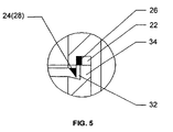
- Fig. 5 illustrates an enlarged view of the portion indicated by A in Fig. 4 .
- Figs. 1-5 illustrating a first embodiment of a battery cover 10 having an upper shell 20 and a lower shell 30.
- the shells 20, 30 can be coupled to each other in order to create a compartment for receiving a cell core or cell and a circuit board (not shown).
- the compartment created by the shells 20, 30 may also be used to store various electronic devices and components.
- the shells 20, 30 can take on rectangular, circular or other polygonal shapes and be fabricated of metal, resin, plastic or other suitable material. To reduce cost and simplify the manufacturing process, the shells 20, 30 can be formed of resin or plastic via injection molding technique.
- the coupling utilizes at least one loop of continuous weld to ensure that the shells 20, 30 are securely fastened to each other.
- the welding technique can include tin welding, gas welding, electric arc welding, laser welding or ultrasonic welding.
- the shells 20, 30 can be formed of resin or plastic material and coupled using ultrasonic welding.
- the shells 20, 30 can be formed of resin or plastic material and coupled using ultrasonic welding with about one to three loops of continuous weld.
- FIGs. 2-3 illustrating cross-sectional views of the upper and lower shells 20, 30, respectively.
- an upper recess 22 and an upper tab 24 are disposed about the edges of the upper shell 20 while a lower recess 32 and a lower tab 34 are disposed about the edges of the lower shell 30.
- the recesses 22, 32 and tabs 24, 34 are continuously disposed about the edges of the shells 20, 30, respectively.
- only one recess 22, 32 and one tab 24, 34 are shown for each shell 20, 30, there may be multiple recesses 22, 32 and tabs 24, 34.
- the upper recess 22 is adaptable for receiving the lower tab 34 while the lower recess 32 is adaptable for receiving the upper tab 24 to provide a secure coupling between the two shells 20, 30.
- a first bond wire 26 is disposed within the upper recess 22 while a second bond wire 28 is disposed about the upper tab 24.
- the second bond wire 28 functions as the upper tab 24.
- the bond wires 26, 28 may also be continuously disposed about the upper shell 20.
- the first bond wire 26 becomes disposed between the upper recess 22 and the lower tab 34 while the second bond wire 28 becomes disposed between the joining of the lower recess 32 and the upper tab 24.
- the bond wires 26, 28 facilitate in the joining of the recesses 22, 32 and tabs 24, 34.
- Figs. 4-5 illustrating cross-sectional views of the battery cover 10 further detailing the coupling between the upper and lower shells 20, 30.
- the lower tab 34 can be received by the upper recess 22 while the upper tab 24 can be received by the lower recess 32 to provide a secure coupling between the two shells 20, 30.
- the first and second bond wires 26, 28 disposed about the upper recess 22 and upper tab 24, respectively are able to be received by the corresponding lower tab 34 and the lower recess 32, respectively.
- the heat generated is able to cause spill over and fusing of the two bond wires 26, 28 to form one loop of continuous weld.
- the bond wires 26, 28 may fuse within the respective regions and become two loops of continuous weld. It will be appreciated by one skilled in the art that additional bond wires 26, 28 may be disposed about the recesses 22, 32 or tabs 24, 34 to provide additional loops of continuous weld.
- the recesses 22, 32 and the tabs 24, 34 may be freely oriented about the shells 20, 30, respectively.
- the upper recess 22 is closer to the edge than the upper tab 24 (e.g., the upper tab 24 is surrounded by the upper recess 22)
- the alternative may be incorporated with the upper recess 22 being enclosed by the upper tab 24.
- the recesses 22, 32 and the tabs 24, 34 may be disposed anywhere about the surfaces of the shells 20, 30 as necessary without restriction.
- bond wires 26, 28 are shown to be disposed about the upper recess 22 and tab 24, respectively, it is understood that the bond wires 26, 28 may also be disposed about the lower recess 32 and tab 34 or any combinations thereof as necessary to provide the necessary coupling. And although the bond wires 26, 28 as shown have rectangular and triangular cross-sections, respectively, it is understood that the bond wires 26, 28 can take other polygonal shapes including trapezoidal cross-sections.
- the process of coupling the shells 20, 30 with heat or solvents can be accomplished by known welding techniques and will not be discussed in further detail.
- adhesives may be disposed about the recesses 22, 32 to further facilitate the coupling of the shells 20, 30, the adhesives being applied to the upper recess 22, the lower recess 32, or both recesses 22, 32.
- adhesives may be applied to the tabs 24, 34.
- Figs. 1-5 illustrates a battery 10 having a cell core, circuit board and shells 20, 30, the cell core and circuit board being situated within the shells 20, 30 whereby the shells 20, 30 are capable of being joined using the presently disclosed embodiments.
- the types of cell core and circuit board and their usages are known by one skilled in the art and will not be described in further detail.
- the shells 20, 30 are able to form at least one loop of continuous weld, they are able to securely maintain the cell core in its position and protect the circuit board and all of its electronic functions.
- the shells 20, 30 are able to minimize and protect against water and moisture from coming into contact with the cell core and circuit board thereby reducing the chances of circuits shorting and exploding, thus increasing the safety and efficiency of the battery.
Landscapes
- Chemical & Material Sciences (AREA)
- Chemical Kinetics & Catalysis (AREA)
- Electrochemistry (AREA)
- General Chemical & Material Sciences (AREA)
- Battery Mounting, Suspending (AREA)
- Sealing Battery Cases Or Jackets (AREA)
Abstract
Description
- This application claims priority to Chinese Patent Application No.
200720183467.X, filed December 3, 2007 - The embodiments of the present invention relate to battery covers.
- During the battery manufacturing process, the cell core and circuit board have to be protected within a cover that is capable of securing the cell core and protecting the electronic functions of the circuit board. The cover may include an upper shell and a lower shell that can be welded together to produce a compartment for housing the cell core and circuit board. However, most of these methods are more concerned about the process of joining the two shells and fail to take into account potential exposures to water and moisture. Furthermore, to reduce cost and increase efficiency, the welding of the upper and lower shells may not be continuous. As such, poor coupling between the shells may lead to water seepage causing shorts and possible explosion of the battery.
-
JP 2005310679 -
JP 2005190852 -
US 2003/0017372 discloses a housing for implantable medical devices. - Accordingly, a first embodiment of the present invention discloses a battery cover comprising: an upper shell and a lower shell coupled to the upper shell using at least one loop of continuous weld, wherein the shells are configured to create a compartment for receiving a cell core and a circuit board. The shells can be formed of resin or plastic material and can further include adhesives to facilitate coupling of the shells to each other.
A battery cover according to the invention comprises: an upper shell having an upper tab with a first bond wire and an upper recess with a second bond wire, and a lower shell having a lower tab and a lower recess, the lower shell adaptable to be coupled to the upper shell, wherein the upper recess is configured to receive the lower tab and the lower recess is configured to receive the upper tab, the first end second bond wires operable to form at least one loop of continuous weld. The bond wires may have rectangular, triangular or trapezoidal cross-sections. Furthermore, adhesives may also be used to facilitate coupling of the shells. Like above, the shells can be formed of resin or plastic material and take on rectangular or circular shapes. In one instance, the shells can be coupled using ultrasonic welding, wherein the shells are configured to create a compartment for receiving a cell core and a circuit board. - Other variations, embodiments and features of the present invention will become evident from the following detailed description, drawings and claims.
-
Fig. 1 illustrates a battery cover having upper and lower shells; -
Fig. 2 illustrates a cross-sectional view of the upper shell; -
Fig. 3 illustrates a cross-sectional view of the lower shell; -
Fig. 4 illustrates a cross-sectional view ofFig. 1 ; and -
Fig. 5 illustrates an enlarged view of the portion indicated by A inFig. 4 . - It will be appreciated by those of ordinary skill in the art that the invention can be embodied in other specific forms without departing from the spirit or essential character thereof. The presently disclosed embodiments are therefore considered in all respects to be illustrative and not restrictive.
- Reference is made to
Figs. 1-5 illustrating a first embodiment of abattery cover 10 having anupper shell 20 and alower shell 30. Theshells shells shells shells - In this instance, the coupling utilizes at least one loop of continuous weld to ensure that the
shells shells shells - Reference is now made to
Figs. 2-3 illustrating cross-sectional views of the upper andlower shells upper recess 22 and anupper tab 24 are disposed about the edges of theupper shell 20 while alower recess 32 and alower tab 34 are disposed about the edges of thelower shell 30. In one instance, therecesses tabs shells recesses tabs tab shell multiple recesses tabs - In one embodiment, the
upper recess 22 is adaptable for receiving thelower tab 34 while thelower recess 32 is adaptable for receiving theupper tab 24 to provide a secure coupling between the twoshells first bond wire 26 is disposed within theupper recess 22 while asecond bond wire 28 is disposed about theupper tab 24. In this case, thesecond bond wire 28 functions as theupper tab 24. Like therecesses tabs bond wires upper shell 20. Subsequently when theshells first bond wire 26 becomes disposed between theupper recess 22 and thelower tab 34 while thesecond bond wire 28 becomes disposed between the joining of thelower recess 32 and theupper tab 24. Thebond wires recesses tabs - Reference is now made to
Figs. 4-5 illustrating cross-sectional views of thebattery cover 10 further detailing the coupling between the upper andlower shells lower shells lower tab 34 can be received by theupper recess 22 while theupper tab 24 can be received by thelower recess 32 to provide a secure coupling between the twoshells second bond wires upper recess 22 andupper tab 24, respectively, are able to be received by the correspondinglower tab 34 and thelower recess 32, respectively. When theshells bond wires bond wires additional bond wires recesses tabs - It will be understood that the
recesses tabs shells upper recess 22 is closer to the edge than the upper tab 24 (e.g., theupper tab 24 is surrounded by the upper recess 22), the alternative may be incorporated with theupper recess 22 being enclosed by theupper tab 24. Likewise, the same applies to thelower recess 32 and thelower tab 34. Also, even though the edges of theshells recesses tabs shells - Likewise, although the
bond wires upper recess 22 andtab 24, respectively, it is understood that thebond wires lower recess 32 andtab 34 or any combinations thereof as necessary to provide the necessary coupling. And although thebond wires bond wires shells - In another embodiment, adhesives may be disposed about the
recesses shells upper recess 22, thelower recess 32, or both recesses 22, 32. In addition, adhesives may be applied to thetabs -
Figs. 1-5 illustrates abattery 10 having a cell core, circuit board andshells shells shells shells shells - Although the invention has been described in detail with reference to several embodiments, additional variations and modifications exist within the scope of the invention as described and defined in the following claims.
Claims (6)
- A battery cover comprising:an upper shell (20); anda lower shell (30) coupled to the upper shell (20) using at least one loop of continuous weld, wherein the shells (20, 30) are configured to create a compartment for receiving a cell core and a circuit board,characterized in thatthe upper shell (20) has an upper tab (24) with a first bond wire (26) and an upper recess (22) with a second bond wire (28); andthe lower shell (30) has a lower tab (34) and a lower recess (32), the lower shell (30) adaptable to be coupled to the upper shell (20), wherein the upper recess (22) is configured to receive the lower tab (34) and the lower recess (32) is configured to receive the upper tab (24), the first and second bond wires (26, 28) operable to form at least one loop of continuous weld.
- The cover of claim 1, wherein the shells can be formed of resin or plastic material.
- The cover of claim 1 or 2, further comprising adhesives for coupling the shells.
- The cover of anyone of claims 1 to 3, wherein the bond wires (26, 28) have rectangular, triangular or trapezoidal cross-sections.
- The cover of claim 1 or 2, wherein the upper or lower recess (22, 32) further includes adhesives for coupling the shells.
- The cover of any one of claims 1 and 3 to 5, wherein the shells (20, 30) can be formed of resin or plastic material in a rectangular or circular shape.
Applications Claiming Priority (1)
| Application Number | Priority Date | Filing Date | Title |
|---|---|---|---|
| CNU200720183467XU CN201122609Y (en) | 2007-12-03 | 2007-12-03 | Battery case and battery including the battery case |
Publications (3)
| Publication Number | Publication Date |
|---|---|
| EP2068382A2 EP2068382A2 (en) | 2009-06-10 |
| EP2068382A3 EP2068382A3 (en) | 2010-02-24 |
| EP2068382B1 true EP2068382B1 (en) | 2011-05-11 |
Family
ID=40009849
Family Applications (1)
| Application Number | Title | Priority Date | Filing Date |
|---|---|---|---|
| EP08020914A Not-in-force EP2068382B1 (en) | 2007-12-03 | 2008-12-02 | Battery cover |
Country Status (4)
| Country | Link |
|---|---|
| US (1) | US8241776B2 (en) |
| EP (1) | EP2068382B1 (en) |
| CN (1) | CN201122609Y (en) |
| AT (1) | ATE509379T1 (en) |
Families Citing this family (12)
| Publication number | Priority date | Publication date | Assignee | Title |
|---|---|---|---|---|
| CN101425678B (en) | 2007-10-30 | 2011-11-23 | 比亚迪股份有限公司 | Battery protection method and system |
| CN201178103Y (en) | 2007-11-24 | 2009-01-07 | 比亚迪股份有限公司 | A lithium-ion battery spacer and a lithium-ion battery containing the spacer |
| CN201122624Y (en) * | 2007-11-30 | 2008-09-24 | 比亚迪股份有限公司 | An electrode lead-out structure and a battery comprising the electrode lead-out structure |
| CN201122609Y (en) | 2007-12-03 | 2008-09-24 | 比亚迪股份有限公司 | Battery case and battery including the battery case |
| CN102074730A (en) * | 2009-11-24 | 2011-05-25 | 欣旺达电子股份有限公司 | Thin-wall plastic frame battery using ultrasonic wave welding way and packaging method thereof |
| CN101800295A (en) * | 2010-04-16 | 2010-08-11 | 沧州荣泰新能源科技有限公司 | Plastic shell of power lithium battery with blocking seal groove on upper cover |
| GB201022043D0 (en) * | 2010-12-24 | 2011-02-02 | Atraverda Ltd | Method of assembling a battery |
| KR20140000770A (en) * | 2012-06-25 | 2014-01-06 | 에스케이이노베이션 주식회사 | Battery module for secondary battery |
| CN104385573A (en) * | 2014-08-28 | 2015-03-04 | 江苏中科天霸新能源科技有限公司 | Welding method for fuel tank of fuel cell |
| CN107615512B (en) * | 2015-12-31 | 2021-01-22 | 深圳市大富精工有限公司 | Battery and battery case thereof |
| CN105576156A (en) * | 2016-02-15 | 2016-05-11 | 东莞市云帆电子科技有限公司 | Battery filled with sealant |
| CN112259864A (en) * | 2020-10-23 | 2021-01-22 | 上海兰钧新能源科技有限公司 | Soft package module, assembly process thereof and electric automobile |
Family Cites Families (22)
| Publication number | Priority date | Publication date | Assignee | Title |
|---|---|---|---|---|
| US3648337A (en) * | 1970-08-24 | 1972-03-14 | Mallory & Co Inc P R | Encapsulating of electronic components |
| JPS56167267A (en) | 1980-05-26 | 1981-12-22 | Shin Kobe Electric Mach Co Ltd | Manufacture of assembled element for lead acid battery |
| JPS59121778A (en) | 1982-12-28 | 1984-07-13 | Yuasa Battery Co Ltd | Manufacturing method for lead storage battery |
| JP3286474B2 (en) | 1994-09-29 | 2002-05-27 | 三洋電機株式会社 | Electric equipment with built-in battery |
| JPH09103034A (en) | 1995-10-06 | 1997-04-15 | Denso Corp | Charger |
| DE60045183D1 (en) | 1999-05-17 | 2010-12-16 | Panasonic Corp | CIRCUIT AND DEVICE FOR THE PROTECTION OF A SECONDARY BATTERY |
| US6413668B1 (en) | 2000-01-10 | 2002-07-02 | Delphi Technologies, Inc. | Lithium ion battery and container |
| US6326766B1 (en) * | 2000-06-09 | 2001-12-04 | Shoot The Moon Products Ii, Llc | Rechargable battery pack and battery pack charger with safety mechanisms |
| ATE460753T1 (en) * | 2001-07-19 | 2010-03-15 | Greatbatch Ltd | CURVED HOUSING FOR AN IMPLANTABLE MEDICAL DEVICE |
| US7129001B2 (en) | 2001-12-18 | 2006-10-31 | Gs Yuasa Corporation | Cell comprising a power-generating element fastened by sheets |
| JP4282470B2 (en) * | 2003-12-25 | 2009-06-24 | 三洋電機株式会社 | Battery pack |
| JP2005216632A (en) * | 2004-01-28 | 2005-08-11 | Sanyo Electric Co Ltd | Battery pack |
| JP2005310679A (en) * | 2004-04-23 | 2005-11-04 | Sanyo Electric Co Ltd | Battery pack |
| JP2006049047A (en) * | 2004-08-03 | 2006-02-16 | Sanyo Electric Co Ltd | Battery pack and method of manufacturing battery pack |
| US7659029B2 (en) | 2004-10-26 | 2010-02-09 | Nissan Motor Co., Ltd. | Battery module with insulating plates nipping electrode tabs |
| CN2829107Y (en) | 2005-06-14 | 2006-10-18 | 惠州Tcl金能电池有限公司 | Leading-out terminal structure of lithium-ion battery |
| CN101075667A (en) | 2006-05-16 | 2007-11-21 | 有量科技股份有限公司 | Lithium battery protection device and method thereof |
| US7968817B2 (en) * | 2006-10-11 | 2011-06-28 | Greatbatch Ltd. | Laser weld process for seam welded electrochemical devices |
| CN101425678B (en) | 2007-10-30 | 2011-11-23 | 比亚迪股份有限公司 | Battery protection method and system |
| CN201178103Y (en) | 2007-11-24 | 2009-01-07 | 比亚迪股份有限公司 | A lithium-ion battery spacer and a lithium-ion battery containing the spacer |
| CN201122624Y (en) | 2007-11-30 | 2008-09-24 | 比亚迪股份有限公司 | An electrode lead-out structure and a battery comprising the electrode lead-out structure |
| CN201122609Y (en) | 2007-12-03 | 2008-09-24 | 比亚迪股份有限公司 | Battery case and battery including the battery case |
-
2007
- 2007-12-03 CN CNU200720183467XU patent/CN201122609Y/en not_active Expired - Fee Related
-
2008
- 2008-10-08 US US12/247,425 patent/US8241776B2/en not_active Expired - Fee Related
- 2008-12-02 AT AT08020914T patent/ATE509379T1/en not_active IP Right Cessation
- 2008-12-02 EP EP08020914A patent/EP2068382B1/en not_active Not-in-force
Also Published As
| Publication number | Publication date |
|---|---|
| US20090142661A1 (en) | 2009-06-04 |
| EP2068382A3 (en) | 2010-02-24 |
| US8241776B2 (en) | 2012-08-14 |
| EP2068382A2 (en) | 2009-06-10 |
| CN201122609Y (en) | 2008-09-24 |
| ATE509379T1 (en) | 2011-05-15 |
Similar Documents
| Publication | Publication Date | Title |
|---|---|---|
| EP2068382B1 (en) | Battery cover | |
| CN1922745B (en) | Integral cap assembly including protective circuit board and secondary battery including the same | |
| KR100699686B1 (en) | Protective circuit module molded body and battery including same | |
| US10553387B1 (en) | Fuse with arc-suppressing housing walls | |
| KR101980151B1 (en) | Printed circuit board and a method of bonding and electrode lead of battery to printed circuit board | |
| JP3614767B2 (en) | Method for forming exterior body of electrical product | |
| JP2017157334A (en) | Secondary battery and assembled battery | |
| US8902594B2 (en) | Electrochemical capacitor | |
| US20100143788A1 (en) | Secondary battery | |
| KR101342603B1 (en) | Battery pack | |
| US8802263B2 (en) | Battery pack and method of manufacturing the same | |
| CN103490103A (en) | Rechargeable battery | |
| CN102448241A (en) | Wiring structure and joint box including the same | |
| JP4097387B2 (en) | Junction box | |
| JP4778699B2 (en) | Battery pack | |
| CN1217831A (en) | Protective device for electronic circuit | |
| US12597673B2 (en) | Battery pack and electronic device | |
| JP5005246B2 (en) | Battery pack and manufacturing method thereof | |
| JP5345995B2 (en) | Protection element assembly and secondary battery provided with the same | |
| JP3909515B2 (en) | Battery pack | |
| JP4837296B2 (en) | Battery pack | |
| KR20180111325A (en) | Secondary battery and method for manufacturing the same | |
| US10998539B2 (en) | Secondary battery and method for manufacturing the same | |
| JP5046568B2 (en) | Battery pack | |
| JP4912350B2 (en) | Manufacturing method of electronic device |
Legal Events
| Date | Code | Title | Description |
|---|---|---|---|
| PUAI | Public reference made under article 153(3) epc to a published international application that has entered the european phase |
Free format text: ORIGINAL CODE: 0009012 |
|
| 17P | Request for examination filed |
Effective date: 20081217 |
|
| AK | Designated contracting states |
Kind code of ref document: A2 Designated state(s): AT BE BG CH CY CZ DE DK EE ES FI FR GB GR HR HU IE IS IT LI LT LU LV MC MT NL NO PL PT RO SE SI SK TR |
|
| AX | Request for extension of the european patent |
Extension state: AL BA MK RS |
|
| PUAL | Search report despatched |
Free format text: ORIGINAL CODE: 0009013 |
|
| AK | Designated contracting states |
Kind code of ref document: A3 Designated state(s): AT BE BG CH CY CZ DE DK EE ES FI FR GB GR HR HU IE IS IT LI LT LU LV MC MT NL NO PL PT RO SE SI SK TR |
|
| AX | Request for extension of the european patent |
Extension state: AL BA MK RS |
|
| AKX | Designation fees paid |
Designated state(s): AT BE BG CH CY CZ DE DK EE ES FI FR GB GR HR HU IE IS IT LI LT LU LV MC MT NL NO PL PT RO SE SI SK TR |
|
| GRAP | Despatch of communication of intention to grant a patent |
Free format text: ORIGINAL CODE: EPIDOSNIGR1 |
|
| GRAC | Information related to communication of intention to grant a patent modified |
Free format text: ORIGINAL CODE: EPIDOSCIGR1 |
|
| GRAS | Grant fee paid |
Free format text: ORIGINAL CODE: EPIDOSNIGR3 |
|
| GRAA | (expected) grant |
Free format text: ORIGINAL CODE: 0009210 |
|
| AK | Designated contracting states |
Kind code of ref document: B1 Designated state(s): AT BE BG CH CY CZ DE DK EE ES FI FR GB GR HR HU IE IS IT LI LT LU LV MC MT NL NO PL PT RO SE SI SK TR |
|
| REG | Reference to a national code |
Ref country code: GB Ref legal event code: FG4D |
|
| REG | Reference to a national code |
Ref country code: CH Ref legal event code: EP |
|
| REG | Reference to a national code |
Ref country code: IE Ref legal event code: FG4D |
|
| REG | Reference to a national code |
Ref country code: DE Ref legal event code: R096 Ref document number: 602008006828 Country of ref document: DE Effective date: 20110622 |
|
| REG | Reference to a national code |
Ref country code: NL Ref legal event code: VDEP Effective date: 20110511 |
|
| PG25 | Lapsed in a contracting state [announced via postgrant information from national office to epo] |
Ref country code: NO Free format text: LAPSE BECAUSE OF FAILURE TO SUBMIT A TRANSLATION OF THE DESCRIPTION OR TO PAY THE FEE WITHIN THE PRESCRIBED TIME-LIMIT Effective date: 20110811 Ref country code: SE Free format text: LAPSE BECAUSE OF FAILURE TO SUBMIT A TRANSLATION OF THE DESCRIPTION OR TO PAY THE FEE WITHIN THE PRESCRIBED TIME-LIMIT Effective date: 20110511 Ref country code: LT Free format text: LAPSE BECAUSE OF FAILURE TO SUBMIT A TRANSLATION OF THE DESCRIPTION OR TO PAY THE FEE WITHIN THE PRESCRIBED TIME-LIMIT Effective date: 20110511 Ref country code: PT Free format text: LAPSE BECAUSE OF FAILURE TO SUBMIT A TRANSLATION OF THE DESCRIPTION OR TO PAY THE FEE WITHIN THE PRESCRIBED TIME-LIMIT Effective date: 20110912 |
|
| PG25 | Lapsed in a contracting state [announced via postgrant information from national office to epo] |
Ref country code: LV Free format text: LAPSE BECAUSE OF FAILURE TO SUBMIT A TRANSLATION OF THE DESCRIPTION OR TO PAY THE FEE WITHIN THE PRESCRIBED TIME-LIMIT Effective date: 20110511 Ref country code: SI Free format text: LAPSE BECAUSE OF FAILURE TO SUBMIT A TRANSLATION OF THE DESCRIPTION OR TO PAY THE FEE WITHIN THE PRESCRIBED TIME-LIMIT Effective date: 20110511 Ref country code: AT Free format text: LAPSE BECAUSE OF FAILURE TO SUBMIT A TRANSLATION OF THE DESCRIPTION OR TO PAY THE FEE WITHIN THE PRESCRIBED TIME-LIMIT Effective date: 20110511 Ref country code: FI Free format text: LAPSE BECAUSE OF FAILURE TO SUBMIT A TRANSLATION OF THE DESCRIPTION OR TO PAY THE FEE WITHIN THE PRESCRIBED TIME-LIMIT Effective date: 20110511 Ref country code: BE Free format text: LAPSE BECAUSE OF FAILURE TO SUBMIT A TRANSLATION OF THE DESCRIPTION OR TO PAY THE FEE WITHIN THE PRESCRIBED TIME-LIMIT Effective date: 20110511 Ref country code: CY Free format text: LAPSE BECAUSE OF FAILURE TO SUBMIT A TRANSLATION OF THE DESCRIPTION OR TO PAY THE FEE WITHIN THE PRESCRIBED TIME-LIMIT Effective date: 20110511 Ref country code: GR Free format text: LAPSE BECAUSE OF FAILURE TO SUBMIT A TRANSLATION OF THE DESCRIPTION OR TO PAY THE FEE WITHIN THE PRESCRIBED TIME-LIMIT Effective date: 20110812 Ref country code: ES Free format text: LAPSE BECAUSE OF FAILURE TO SUBMIT A TRANSLATION OF THE DESCRIPTION OR TO PAY THE FEE WITHIN THE PRESCRIBED TIME-LIMIT Effective date: 20110822 Ref country code: IS Free format text: LAPSE BECAUSE OF FAILURE TO SUBMIT A TRANSLATION OF THE DESCRIPTION OR TO PAY THE FEE WITHIN THE PRESCRIBED TIME-LIMIT Effective date: 20110911 |
|
| PG25 | Lapsed in a contracting state [announced via postgrant information from national office to epo] |
Ref country code: NL Free format text: LAPSE BECAUSE OF FAILURE TO SUBMIT A TRANSLATION OF THE DESCRIPTION OR TO PAY THE FEE WITHIN THE PRESCRIBED TIME-LIMIT Effective date: 20110511 |
|
| PG25 | Lapsed in a contracting state [announced via postgrant information from national office to epo] |
Ref country code: CZ Free format text: LAPSE BECAUSE OF FAILURE TO SUBMIT A TRANSLATION OF THE DESCRIPTION OR TO PAY THE FEE WITHIN THE PRESCRIBED TIME-LIMIT Effective date: 20110511 Ref country code: EE Free format text: LAPSE BECAUSE OF FAILURE TO SUBMIT A TRANSLATION OF THE DESCRIPTION OR TO PAY THE FEE WITHIN THE PRESCRIBED TIME-LIMIT Effective date: 20110511 |
|
| PG25 | Lapsed in a contracting state [announced via postgrant information from national office to epo] |
Ref country code: DK Free format text: LAPSE BECAUSE OF FAILURE TO SUBMIT A TRANSLATION OF THE DESCRIPTION OR TO PAY THE FEE WITHIN THE PRESCRIBED TIME-LIMIT Effective date: 20110511 Ref country code: SK Free format text: LAPSE BECAUSE OF FAILURE TO SUBMIT A TRANSLATION OF THE DESCRIPTION OR TO PAY THE FEE WITHIN THE PRESCRIBED TIME-LIMIT Effective date: 20110511 Ref country code: PL Free format text: LAPSE BECAUSE OF FAILURE TO SUBMIT A TRANSLATION OF THE DESCRIPTION OR TO PAY THE FEE WITHIN THE PRESCRIBED TIME-LIMIT Effective date: 20110511 Ref country code: RO Free format text: LAPSE BECAUSE OF FAILURE TO SUBMIT A TRANSLATION OF THE DESCRIPTION OR TO PAY THE FEE WITHIN THE PRESCRIBED TIME-LIMIT Effective date: 20110511 |
|
| PLBE | No opposition filed within time limit |
Free format text: ORIGINAL CODE: 0009261 |
|
| STAA | Information on the status of an ep patent application or granted ep patent |
Free format text: STATUS: NO OPPOSITION FILED WITHIN TIME LIMIT |
|
| 26N | No opposition filed |
Effective date: 20120214 |
|
| PG25 | Lapsed in a contracting state [announced via postgrant information from national office to epo] |
Ref country code: HR Free format text: LAPSE BECAUSE OF FAILURE TO SUBMIT A TRANSLATION OF THE DESCRIPTION OR TO PAY THE FEE WITHIN THE PRESCRIBED TIME-LIMIT Effective date: 20111123 Ref country code: IT Free format text: LAPSE BECAUSE OF FAILURE TO SUBMIT A TRANSLATION OF THE DESCRIPTION OR TO PAY THE FEE WITHIN THE PRESCRIBED TIME-LIMIT Effective date: 20110511 |
|
| REG | Reference to a national code |
Ref country code: DE Ref legal event code: R097 Ref document number: 602008006828 Country of ref document: DE Effective date: 20120214 |
|
| PG25 | Lapsed in a contracting state [announced via postgrant information from national office to epo] |
Ref country code: MC Free format text: LAPSE BECAUSE OF NON-PAYMENT OF DUE FEES Effective date: 20111231 |
|
| REG | Reference to a national code |
Ref country code: IE Ref legal event code: MM4A |
|
| PG25 | Lapsed in a contracting state [announced via postgrant information from national office to epo] |
Ref country code: IE Free format text: LAPSE BECAUSE OF NON-PAYMENT OF DUE FEES Effective date: 20111202 |
|
| PG25 | Lapsed in a contracting state [announced via postgrant information from national office to epo] |
Ref country code: MT Free format text: LAPSE BECAUSE OF FAILURE TO SUBMIT A TRANSLATION OF THE DESCRIPTION OR TO PAY THE FEE WITHIN THE PRESCRIBED TIME-LIMIT Effective date: 20110511 |
|
| PG25 | Lapsed in a contracting state [announced via postgrant information from national office to epo] |
Ref country code: LU Free format text: LAPSE BECAUSE OF NON-PAYMENT OF DUE FEES Effective date: 20111202 |
|
| PG25 | Lapsed in a contracting state [announced via postgrant information from national office to epo] |
Ref country code: BG Free format text: LAPSE BECAUSE OF FAILURE TO SUBMIT A TRANSLATION OF THE DESCRIPTION OR TO PAY THE FEE WITHIN THE PRESCRIBED TIME-LIMIT Effective date: 20110811 |
|
| REG | Reference to a national code |
Ref country code: CH Ref legal event code: PL |
|
| PG25 | Lapsed in a contracting state [announced via postgrant information from national office to epo] |
Ref country code: TR Free format text: LAPSE BECAUSE OF FAILURE TO SUBMIT A TRANSLATION OF THE DESCRIPTION OR TO PAY THE FEE WITHIN THE PRESCRIBED TIME-LIMIT Effective date: 20110511 |
|
| PG25 | Lapsed in a contracting state [announced via postgrant information from national office to epo] |
Ref country code: CH Free format text: LAPSE BECAUSE OF NON-PAYMENT OF DUE FEES Effective date: 20121231 Ref country code: HU Free format text: LAPSE BECAUSE OF FAILURE TO SUBMIT A TRANSLATION OF THE DESCRIPTION OR TO PAY THE FEE WITHIN THE PRESCRIBED TIME-LIMIT Effective date: 20110511 Ref country code: LI Free format text: LAPSE BECAUSE OF NON-PAYMENT OF DUE FEES Effective date: 20121231 |
|
| PG25 | Lapsed in a contracting state [announced via postgrant information from national office to epo] |
Ref country code: HR Free format text: LAPSE BECAUSE OF FAILURE TO SUBMIT A TRANSLATION OF THE DESCRIPTION OR TO PAY THE FEE WITHIN THE PRESCRIBED TIME-LIMIT Effective date: 20110511 |
|
| REG | Reference to a national code |
Ref country code: FR Ref legal event code: PLFP Year of fee payment: 8 |
|
| REG | Reference to a national code |
Ref country code: FR Ref legal event code: PLFP Year of fee payment: 9 |
|
| PGFP | Annual fee paid to national office [announced via postgrant information from national office to epo] |
Ref country code: GB Payment date: 20161222 Year of fee payment: 9 Ref country code: DE Payment date: 20161213 Year of fee payment: 9 |
|
| PGFP | Annual fee paid to national office [announced via postgrant information from national office to epo] |
Ref country code: FR Payment date: 20161222 Year of fee payment: 9 |
|
| REG | Reference to a national code |
Ref country code: DE Ref legal event code: R119 Ref document number: 602008006828 Country of ref document: DE |
|
| GBPC | Gb: european patent ceased through non-payment of renewal fee |
Effective date: 20171202 |
|
| REG | Reference to a national code |
Ref country code: FR Ref legal event code: ST Effective date: 20180831 |
|
| PG25 | Lapsed in a contracting state [announced via postgrant information from national office to epo] |
Ref country code: FR Free format text: LAPSE BECAUSE OF NON-PAYMENT OF DUE FEES Effective date: 20180102 Ref country code: DE Free format text: LAPSE BECAUSE OF NON-PAYMENT OF DUE FEES Effective date: 20180703 |
|
| PG25 | Lapsed in a contracting state [announced via postgrant information from national office to epo] |
Ref country code: GB Free format text: LAPSE BECAUSE OF NON-PAYMENT OF DUE FEES Effective date: 20171202 |