EP2068038A1 - Reduction gear - Google Patents
Reduction gear Download PDFInfo
- Publication number
- EP2068038A1 EP2068038A1 EP07828462A EP07828462A EP2068038A1 EP 2068038 A1 EP2068038 A1 EP 2068038A1 EP 07828462 A EP07828462 A EP 07828462A EP 07828462 A EP07828462 A EP 07828462A EP 2068038 A1 EP2068038 A1 EP 2068038A1
- Authority
- EP
- European Patent Office
- Prior art keywords
- carrier
- support shaft
- crank member
- reduction gear
- central axis
- Prior art date
- Legal status (The legal status is an assumption and is not a legal conclusion. Google has not performed a legal analysis and makes no representation as to the accuracy of the status listed.)
- Granted
Links
Images




Classifications
-
- F—MECHANICAL ENGINEERING; LIGHTING; HEATING; WEAPONS; BLASTING
- F16—ENGINEERING ELEMENTS AND UNITS; GENERAL MEASURES FOR PRODUCING AND MAINTAINING EFFECTIVE FUNCTIONING OF MACHINES OR INSTALLATIONS; THERMAL INSULATION IN GENERAL
- F16H—GEARING
- F16H1/00—Toothed gearings for conveying rotary motion
- F16H1/28—Toothed gearings for conveying rotary motion with gears having orbital motion
- F16H1/36—Toothed gearings for conveying rotary motion with gears having orbital motion with two central gears coupled by intermeshing orbital gears
-
- F—MECHANICAL ENGINEERING; LIGHTING; HEATING; WEAPONS; BLASTING
- F16—ENGINEERING ELEMENTS AND UNITS; GENERAL MEASURES FOR PRODUCING AND MAINTAINING EFFECTIVE FUNCTIONING OF MACHINES OR INSTALLATIONS; THERMAL INSULATION IN GENERAL
- F16H—GEARING
- F16H1/00—Toothed gearings for conveying rotary motion
- F16H1/28—Toothed gearings for conveying rotary motion with gears having orbital motion
- F16H1/32—Toothed gearings for conveying rotary motion with gears having orbital motion in which the central axis of the gearing lies inside the periphery of an orbital gear
Definitions
- the present invention relates to a reduction gear transmission utilized in an industrial robot or a machine tool, etc.
- the present invention relates to a reduction gear transmission that is a kind of eccentrically oscillating type reduction gear transmission.
- the external gear rotates with respect to the internal gear when the external gear is caused to revolve orbitally around a central axis of the internal gear while the two are maintaining a meshed state.
- An eccentrically oscillating type of reduction gear transmission that utilizes this phenomenon has been developed, and such is taught, for example, in Japanese Patent Application Publication No. 1997-57678 .
- This type of reduction gear transmission comprises an internal gear, an external gear, a carrier, a crankshaft, and a bearing.
- the external gear rotates while revolving orbitally around the central axis of the internal gear while maintaining a meshed state with the internal gear.
- a plurality of through holes formed at positions offset from the center are formed in the external gear.
- the carrier is supported so as to be capable of rotating around the central axis of the internal gear.
- the crankshaft is attached to the carrier in a manner that allows the rotation of the crankshaft.
- the crankshaft comprises a shaft part and an eccentric member that has a central axis formed in a position offset from a central axis of the shaft part.
- the eccentric member of the crankshaft engages with the through hole of the external gear.
- the bearing is disposed between the carrier and the shaft part of the crankshaft, and supports the shaft part of the crankshaft such that it can rotate with respect to the carrier. In the configuration described above, when the crankshaft is rotated by a motor, the eccentric member of the crankshaft rotates eccentrically.
- the eccentric member of the crankshaft rotates eccentrically
- the external gear rotates while revolving orbitally around the central axis of the internal gear.
- the carrier rotates with respect to the internal gear.
- the rotation of the crankshaft can be transmitted to the rotation of the carrier, and the number of rotations of the carrier can be reduced compared to the number of rotations of the crankshaft.
- the crankshaft In the eccentrically oscillating type reduction gear transmission, the crankshaft must be provided such that it can rotate with respect to the carrier.
- the shaft part of the crankshaft is supported by a tapered roller bearing, and the crankshaft is thus supported such that it can rotate with respect to the carrier.
- the shaft part is formed on the crankshaft, and this shaft part is supported by the bearing.
- the shaft part of the crankshaft extends from the eccentric member towards both sides in the rotation axis direction of the crankshaft, and consequently the length of the crankshaft in its rotation axis direction is increased. As a result, the length of the reduction gear transmission in its rotation axis direction is increased.
- the present invention solves the above problem.
- the present invention teaches a technique that decreases the length of the reduction gear transmission in its rotation axis direction.
- a reduction gear transmission of the present invention comprises at least an internal gear, an external gear, a carrier, a crank member, and a bearing mechanism.
- the external gear comprises a through hole at a position offset from its central axis, wherein the external gear is supported such that the external gear is capable of rotating on its central axis while revolving with respect to a central axis of the internal gear while maintaining a meshed state with the internal gear.
- the carrier comprises a support shaft that extends into the through hole of the external gear. The carrier is supported such that the carrier is capable of rotating with respect to the central axis of the internal gear.
- the crank member comprises a though hole into which the support shaft extends and an eccentric member that engages inside the through hole of the external gear.
- a central axis of the eccentric member is offset from a central axis of the support shaft.
- the bearing mechanism comprises an inner ring into which the support shaft of the carrier fits and an outer ring that fits into the through hole of the crank member.
- the bearing mechanism supports the crank member such that the crank member is capable of rotating with respect to the central axis of the support shaft.
- a clearance that extends along the support shaft between the carrier and the inner ring is narrower than a clearance that extends along the support shaft between the carrier and an end face of the crank member.
- the term that "the clearance between the carrier and the inner ring being narrower than the clearance between the carrier and the crank member" also includes the case in which a clearance is not present between the carrier and the inner ring.
- the bearing mechanism is provided between the crank member and the support shaft formed on the carrier, and the crank member is supported so as to be capable of rotating with respect to the support shaft.
- the crank member thus no longer needs to be provided with a shaft part specifically for mounting the bearing mechanism. It is possible to reduce the size of the reduction gear transmission in its rotation axis direction by reducing the length of the crank member in its rotation axis direction.
- the bearing mechanism is disposed between the support shaft and the crank member and the length of the reduction gear transmission in its rotation axis direction is reduced, it may no longer be possible to maintain an adequate clearance between the crank member and the carrier (a clearance extending in the rotation axis direction).
- the crank member and the carrier may make contact if the crank member moves even slightly in the axial direction of the support shaft.
- the clearance that extends along the support shaft between the carrier and the inner ring of the bearing mechanism is narrower than the clearance between the carrier and the end face of the crank member. The clearance between the crank member and the carrier can thus be maintained even in the case where the bearing mechanism has moved to its maximum extent in the axial direction of the support shaft. According to this reduction gear transmission, it is possible to reliably prevent the crank member and the carrier from making contact, and the length of the reduction gear transmission in its rotation axis direction can be significantly reduced.
- a spacer member is disposed between the carrier and the bearing mechanism.
- the spacer member it is possible to adjust the clearance extending along the support shaft between the carrier and the inner ring of the bearing mechanism.
- the clearance extending along the support shaft between the carrier and the inner ring of the bearing mechanism can reliably be made narrower than the clearance between the carrier and the end face of the crank member.
- the carrier comprises a protrusion that protrudes along the support shaft and toward the inner ring of the bearing mechanism. It is thereby possible to reliably make the clearance extending along the support shaft between the carrier and the inner ring of the bearing mechanism narrower than the clearance between the carrier and the crank member without using the spacer member, or by using the protrusion in combination with the spacer member.
- the inner ring of the bearing mechanism comprises a protrusion that protrudes along the support shaft and toward the carrier. It is thereby possible to reliably make the clearance extending along the support shaft between the carrier and the inner ring of the bearing mechanism narrower than the clearance between the carrier and the crank member without using the spacer member, or by using the protrusion that protrudes toward the carrier in combination with the spacer member.
- the support shaft comprises an expanded portion at which the diameter of the support shaft is expanded.
- the support shaft is partially composed of the expanded portion along its axial direction, and the bearing mechanism comprises a pair of bearings.
- the expanded portion of the support shaft is disposed between the pair of bearings.
- the bearing mechanisms are prevented from moving in the axial direction of the support shaft by the expanded portion of the support shaft. The bearing mechanisms can be maintained correctly in position by the spacer member, etc. and the expanded portion of the support shaft.
- the pair of bearings is a pair of tapered roller bearings. It is thereby possible to prevent the crank member from moving in the axial direction of the support shaft.
- the clearance between the crank member and the carrier can be made comparatively small, and the size of the reduction gear transmission in its rotation axis direction can be further reduced.
- the length of the reduction gear transmission in its rotation axis direction can be reduced and, for example, a joint part of an industrial robot can be configured in a compact manner.
- FIG. 1 shows a reduction gear transmission 10 in which the present invention has been realized.
- the reduction gear transmission 10 can be suitably used in, for example, a joint part 100 of an industrial robot.
- the joint part 100 comprises a first arm 102, a second arm 104, the reduction gear transmission 10, and a motor 106.
- the second arm 104 is connected via the reduction gear transmission 10 to the first arm 102 in a manner capable of swinging.
- the reduction gear transmission 10 also has a hollow structure having a central hole 42.
- the motor 106 has a hollow structure having a central hole 108.
- the central hole 42 of the reduction gear transmission 10 and the central hole 108 of the motor 106 communicate with one another, and electrical wiring, etc. can be disposed from the first arm 102 side to the second arm 104 side through these central holes 42 and 108.
- the reduction gear transmission 10 comprises an internal gear 20, a carrier 30, an input shaft 40, three crank members 60, and a pair of external gears 80a and 80b.
- the internal gear 20 is fixed, together with the motor 106, to the first arm 102.
- the carrier 30 is fixed to the second arm 104.
- the input shaft 40 is fixed to an output shaft (not shown) of the motor 106.
- the reduction gear transmission 10 when the input shaft 40 is rotated by the motor 106, the pair of external gears 80a and 80b rotates while revolving orbitally with respect to the internal gear 20, and the carrier 30 rotates with respect to the internal gear 20.
- the speed of rotation of the motor 106 is reduced, that is, the rotary torque of the motor 106 is amplified.
- the second arm 104 thereby swings with respect to the first arm 102 at low speed and high torque.
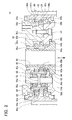
- FIG. 2 shows the configuration of the reduction gear transmission 10.
- FIG. 3 shows a plan view viewed in the direction of the arrow III of FIG. 2 .
- the configuration of the reduction gear transmission 10 will be described in detail with reference to FIGS. 2 and 3 .
- the internal gear 20 has a cylindrical shape.
- a plurality of pins 22 is disposed equidistantly along an inner circumferential surface of the internal gear 20.
- the internal gear 20 is an internal gear type pin gear.
- a plurality of holes 24 is formed in the internal gear 20. These holes 24 allow the passage of bolts or the like used for fixing.
- the pair of external gears 80a and 80b has an identical shape.
- the external gears 80a and 80b are approximately disc shaped.
- Gear parts 82a and 82b that mesh with the gear pins 22 of the internal gear 20 are formed along an outer circumferential surface of the external gears 80a and 80b.
- the following are formed in the external gears 80a and 80b: three pairs of carrier through holes 84a and 84b, and three pairs of crank through holes 86a and 86b.
- the external gear 80a that is positioned at an upper side in FIG. 2 will be termed "a first external gear 80a”
- the external gear 80b that is positioned at a lower side in FIG. 2 will be termed "a second external gear 80b”.
- the carrier 30 comprises a pair of sheet shaped parts 30a and 30c that faces one another, and three columnar members 30b that extend between the pair of sheet shaped parts 30a and 30c.
- the pair of sheet shaped parts 30a and 30c is positioned at each of the ends in an axial direction of the pair of external gears 80a and 80b. That is, the external gears 80a and 80b of the pair have a positional relationship such that they are housed between the pair of sheet shaped parts 30a and 30c.
- the three columnar members 30b are disposed equidistantly along a circumferential direction.
- the carrier 30 has a configuration in which the pair of sheet shaped parts 30a and 30c is joined by the plurality of columnar members 30b.
- one of the sheet shaped parts 30a (at the upper side in FIG. 2 ) is formed integrally with the three columnar members 30b, and the other of the sheet shaped parts 30c (at the lower side in FIG. 2 ) is fixed to the columnar members 30b by a plurality of bolts 32.
- the sheet shaped part 30a positioned at the upper side in FIG. 2 may be termed "a first sheet shaped part 30a”
- the sheet shaped part 30c positioned at the lower side in FIG. 2 may be termed "a second sheet shaped part 30c”.
- the columnar members 30b pass through the carrier through holes 84a and 84b of the external gears 80a and 80b.
- a clearance is formed between each of the columnar members 30b and the respective carrier through holes 84a and 84b, this clearance allows the external gears 80a and 80b to rotate eccentrically (revolve orbitally) with respect to the carrier 30.
- three support shafts 50 are formed on the carrier 30. One end part (at the upper side in FIG. 2 ) of the support shafts 50 is fixed to the first sheet shaped part 30a, and the other end part (at the lower side in FIG. 2 ) of the support shafts 50 is fixed to the second sheet shaped part 30c.
- the support shafts 50 extend between the pair of sheet shaped parts 30a and 30c of the carrier 30.
- the support shafts 50 pass through the crank through holes 86a and 86b of the external gears 80a and 80b.
- An expanded portion 52 in which the diameter of the support shaft 50 is configured greater than the remaining portion is formed at a central part in an axial direction of the support shafts 50.
- the carrier 30 is attached to the internal gear 20 via a pair of angular ball bearings 28a and 28b.
- the carrier 30 is supported so as to be capable of rotating with respect to the internal gear 20. Oil seals 29a and 29b are formed between the carrier 30 and the internal gear 20.
- the crank members 60 are attached to the support shafts 50 via a pair of tapered roller bearings 56a and 56b.
- the crank members 60 each has an approximately cylindrical shape, and the pair of tapered roller bearings 56a and 56b are housed within through holes 66 of the crank members 60.
- the pair of tapered roller bearings 56a and 56b allows the respective crank member 60 to rotate around the respective support shaft 50 and prevents the crank member 60 from moving in the axial direction of the respective support shaft 50.
- the expanded portion 52 of the respective support shafts 50 is disposed between the pair of tapered roller bearings 56a and 56b. Stopping rings 46a and 46b for preventing removal are attached inside the through holes 66 of the crank members 60.
- the tapered roller bearing 56a positioned at the upper side in FIG. 2 may be termed "a first tapered roller bearing 56a”
- the tapered roller bearing 56b positioned at the lower side in FIG. 2 may be termed "a second tapered roller bearing 56b".
- a pair of eccentric members 62a and 62b and a follower gear 68 are formed on each of the crank members 60.
- the eccentric members 62a and 62b are disc shaped, and their respective central axis thereof is offset in a radial direction from a rotation central axis (i.e. a central axis of the support shaft 50) of the crank member 60.
- the first eccentric member 62a (at the upper side in FIG. 2 ) and the second eccentric member 62b (at the lower side in FIG. 2 ) are offset in opposing directions with respect to each other, and the two rotate eccentrically with a phase difference of 180 degrees.
- the first eccentric member 62a fits into the crank through hole 86a of the first external gear 80a via a needle shaped roller bearing 64a.
- the second eccentric member 62b fits into the crank through hole 86b of the second external gear 80b via a needle shaped roller bearing 64b.
- the first external gear 80a and the second external gear 80b are thereby driven by the rotation of the crank member 60 to rotate eccentrically with a phase difference of 180 degrees.
- the eccentric rotation caused by the crank member 60 causes the first external gear 80a and the second external gear 80b to rotate while revolving orbitally with respect to the internal gear 20 while maintaining a meshed state with the internal gear 20.
- At least a part of the tapered roller bearings 56a or 56b being the pair thereof is positioned within the range of the length in the axial direction in which the eccentric members 62a and 62b of the crank member 60 are formed.
- the reduction gear transmission 10 can thereby be reduced in length in its rotation axis direction; shorter in comparison with a configuration in which, for example, the crank member 60 is supported by a thrust bearing or the like.
- the input shaft 40 is provided with a driving gear 44.
- the driving gear 44 meshes with the follower gears 68 of the crank members 60.
- Each of the crank members 60 thus rotates when the input shaft 40 rotates.
- Oil seals 36a and 36b are formed between the input shaft 40 and the carrier 30.
- the through hole 42 is formed in the input shaft 40, and electrical wiring or the like can be disposed within the through hole 42.
- FIG. 4 shows an enlargement of an assembly portion of the crank member 60.
- inner rings 57a and 57b of the pair of tapered roller bearings 56a and 56b fit into the support shafts 50
- outer rings 58a and 58b of the pair of tapered roller bearings 56a and 56b fit into the through holes 66 of the crank members 60.
- a cylindrical spacer 54a is formed between the inner ring 57a of the first tapered roller bearing 56a and the first sheet shaped part 30a of the carrier 30.
- a cylindrical spacer 54b is formed between the inner ring 57b of the second tapered roller bearing 56b and the second sheet shaped part 30c of the carrier 30.
- a clearance along which the support shaft 50 extends is thus formed between the inner rings 57a and 57b of the tapered roller bearings 56a and 56b and the sheet shaped parts 30a and 30c of the carrier 30. Further, the expanded portion 52 of the support shaft 50 protrudes between the pair of tapered roller bearings 56a and 56b.
- the inner rings 57a and 57b of the tapered roller bearings 56a and 56b are held by the cylindrical spacers 54a and 54b and the expanded portion 52 of the support shaft 50, thereby preventing the tapered roller bearings 56a and 56b from moving in the axial direction of the support shaft 50.
- a clearance D (the clearance along a direction which the support shaft 50 extends) is maintained between the crank member 60 and the sheet shaped parts 30a and 30c of the carrier 30.
- the crank member 60 is prevented from making contact with the sheet shaped parts 30a and 30c of the carrier 30 even if the clearance D between the crank member 60 and the carrier 30 is set to be comparatively narrow. Since the clearance D between the crank member 60 and the carrier 30 can be set to be comparatively narrow, it is possible to decrease the length of the reduction gear transmission 10 in its rotation axis direction.
- a clearance may be formed between the inner rings 57a and 57b of the tapered roller bearings 56a and 56b and the sheet shaped parts 30a and 30c of the carrier 30 based on, for example, allowances that arise due to accuracy of the components or accuracy in assembly.
- a predetermined clearance may be designed between the inner rings 57a and 57b and the sheet shaped parts 30a and 30c with taking the allowances rising from accuracy of the components or accuracy in assembly into consideration. For example, in the case of the present embodiment, as shown in FIG.
- a clearance E along a direction which the support shaft 50 extends may be formed between the inner rings 57a and 57b and the sheet shaped parts 30a and 30c by reducing the height to which the cylindrical spacers 54a and 54b rise.
- the clearance E that is present between the inner rings 57a and 57b and the sheet shaped parts 30a and 30c must be narrower than the clearance D between the crank member 60 and the sheet shaped parts 30a and 30c of the carrier 30.
- the present embodiment has a configuration in which the outer rings 58a and 58b of the pair of tapered roller bearings 56a and 56b are completely housed within the through holes 66 of the crank members 60.
- the outer rings 58a and 58b do not necessarily need to be completely housed within the through holes 66 of the crank members 60, and the present embodiment may have a configuration in which a part of the outer rings 58a and 58b is housed within the through holes 66 of the crank members 60.
- the clearance E between the inner rings 57a and 57b and the sheet shaped parts 30a and 30c may be designed narrower than a clearance (a clearance along which the support shaft 50 extends) between the outer rings 58a and 58b and the sheet shaped parts 30a and 30c of the carrier 30.
- the expanded portion 52 of the support shaft 50, and the inner rings 57a and 57b of the tapered roller bearings 56a and 56b are supported by the cylindrical spacers 54a and 54b between the pair of sheet shaped parts 30a and 30c of the carrier 30.
- the distance between the pair of sheet shaped parts 30a and 30c is thereby maintained even in the case where external force is applied to the pair of sheet shaped parts 30a and 30c, and consequently the crank member 60 is prevented from making contact with the sheet shaped parts 30a and 30c of the carrier 30.
- the expanded portion 52 of the support shaft 50 is held by the pair of tapered roller bearings 56a and 56b.
- the support shaft 50 is thereby prevented from moving in an axial direction with respect to the carrier 30, and the support shaft 50 is prevented from falling off the carrier 30.
- the operation of the reduction gear transmission 10 will be described.
- the driving gear 44 formed on the input shaft 40 rotates.
- the crank member 60 rotates around the support shaft 50 as the follower gear 68 that is meshing with the driving gear 44 rotates.
- the crank member 60 rotates without making contact with the carrier 30 due to the assembled structure of the crank member shown in FIG. 4 .
- the rotation of the crank member 60 causes the first eccentric member 62a and the second eccentric member 62b of the crank member 60 to rotate eccentrically with the phase difference of 180 degrees.
- the first external gear 80a rotates while revolving orbitally around the central axis of the internal gear 20 while maintaining a meshed state with the internal gear 20.
- the second external gear 80b rotates while revolving orbitally around the central axis of the internal gear 20 while maintaining a meshed state with the internal gear 20.
- the first external gear 80a and the second external gear 80b revolve orbitally with the phase difference of 180 degrees.
- the ratio of the number of orbital revolutions of the external gears 80a and 80b to the number of rotations is determined by the relationship between the number of teeth of the external gears 80a and 80b and the number of teeth of the internal gear 20. For example, in the case where the difference in number of teeth is one, with the number of teeth of the internal gear 20 being fifty-two and the number of teeth of the external gears 80a and 80b being fifty-one, one rotation of the external gears 80a and 80b is caused by 52 orbital revolutions of the external gears 80a and 80b. As a result, the number of rotations is reduced by 1/52 between the external gears 80a and 80b and the internal gear 20.
- the carrier 30 is rotated with respect to the internal gear 20 by the rotation of the external gears 80a and 80b. As shown in FIG. 1 , the internal gear 20 is fixed to the first arm 102 side, and the carrier 30 is fixed to the second arm 104 side, thus allowing the second arm 104 to swing with respect to the first arm 102.
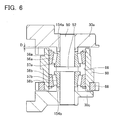
- FIG. 6 shows the assembled structure of the crank member 60 described in the present embodiment.
- a configuration equivalent to the cylindrical spacers 54a and 54b used in embodiment 1 is formed integrally on the sheet shaped parts 30a and 30c of the carrier 30. That is, protrusions 154a and 154b that protrude along the support shafts 50 toward the tapered roller bearings 56a and 56b are formed on the respective sheet shaped parts 30a and 30c of the carrier 30.
- the protrusions 154a and 154b can prevent excess space (e.g.
- the protrusions 154a and 154b prevent the tapered roller bearings 56a and 56b from moving in the axial direction of the support shaft 50.
- the crank member 60 can be prevented from making contact with the sheet shaped parts 30a and 30c of the carrier 30. Compared to the configuration of embodiment 1, the number of components can be reduced, and the assembly process of the reduction gear transmission 10 becomes easier.
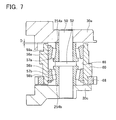
- FIG. 7 shows the assembled structure of the crank member 60 described in the present embodiment.
- a configuration equivalent to the cylindrical spacers 54a and 54b used in embodiment 1 is formed integrally on the inner rings 57a and 57b of the tapered roller bearings 56a and 56b. That is, protrusions 254a and 254b that protrude along the support shafts 50 toward the sheet shaped parts 30a and 30c of the carrier 30 are formed on the inner rings 57a and 57b of the tapered roller bearings 56a and 56b.
- the protrusions 254a and 254b can prevent excess space (e.g. greater than the clearance D) from being formed between the inner rings 57a and 57b of the tapered roller bearings 56a and 56b and the sheet shaped parts 30a and 30c of the carrier 30.
- the protrusions 254a and 254b prevent the tapered roller bearings 56a and 56b from moving in the axial direction of the support shaft 50.
- the crank member 60 can be prevented from making contact with the sheet shaped parts 30a and 30c of the carrier 30.
- the number of components can be reduced, and the assembly process of the reduction gear transmission 10 becomes easier.
- FIG. 8 shows the assembled structure of the crank member 60 described in the present embodiment.
- stopping rings 354a and 354b that can each be attached to the support shafts 50 in a manner allowing removal are provided.
- the stopping rings 354a and 354b can prevent excess space (e.g. greater than the clearance D) from being formed between the inner rings 57a and 57b of the tapered roller bearings 56a and 56b and the sheet shaped parts 30a and 30c of the carrier 30.
- the "space” referred to here means a space (clearance) allowing the tapered roller bearings 56a and 56b to move in the axial direction of the support shaft 50.
- the "space” in this case refers to a space formed between the stopping rings 354a and 354b and the sheet shaped parts 30a and 30c of the carrier 30.
- the stopping rings 354a and 354b prevent movement in the axial direction of the support shaft 50, thereby preventing the tapered roller bearings 56a and 56b from moving in the axial direction of the support shaft 50.
- the crank member 60 can be prevented from making contact with the sheet shaped parts 30a and 30c of the carrier 30.
- the carrier 30 has a configuration provided with sufficient structural strength, it is not necessary to provide the columnar members 30b on the carrier 30.
- three crank members 60 have been utilized.
- the number of crank members 60 is not restricted to three.
- the number of crank members 60 may be less than three, or may be four or more.
- two external gears 80a and 80b have been utilized.
- the number of external gears is not restricted to two.
- the number of external gears may be one, or may be three or more. If the number of external gears is reduced, the length of the reduction gear transmission in the rotation axis direction can be reduced. If the number of external gears is increased, the rotational balance of the reduction gear transmission improves.
- the number of external gears can be selected in accordance with the aim and intended use of the reduction gear transmission.
Landscapes
- Engineering & Computer Science (AREA)
- General Engineering & Computer Science (AREA)
- Mechanical Engineering (AREA)
- Retarders (AREA)
Abstract
Description
- This application claims priority to Japanese Patent Application No.
2006-268655, filed on September 29, 2006
The present invention relates to a reduction gear transmission utilized in an industrial robot or a machine tool, etc. In particular, the present invention relates to a reduction gear transmission that is a kind of eccentrically oscillating type reduction gear transmission. - In preparing an internal gear and an external gear, the external gear rotates with respect to the internal gear when the external gear is caused to revolve orbitally around a central axis of the internal gear while the two are maintaining a meshed state. An eccentrically oscillating type of reduction gear transmission that utilizes this phenomenon has been developed, and such is taught, for example, in Japanese Patent Application Publication No.
1997-57678
The external gear rotates while revolving orbitally around the central axis of the internal gear while maintaining a meshed state with the internal gear. A plurality of through holes formed at positions offset from the center are formed in the external gear. The carrier is supported so as to be capable of rotating around the central axis of the internal gear. The crankshaft is attached to the carrier in a manner that allows the rotation of the crankshaft. The crankshaft comprises a shaft part and an eccentric member that has a central axis formed in a position offset from a central axis of the shaft part. The eccentric member of the crankshaft engages with the through hole of the external gear. The bearing is disposed between the carrier and the shaft part of the crankshaft, and supports the shaft part of the crankshaft such that it can rotate with respect to the carrier.
In the configuration described above, when the crankshaft is rotated by a motor, the eccentric member of the crankshaft rotates eccentrically. When the eccentric member of the crankshaft rotates eccentrically, the external gear rotates while revolving orbitally around the central axis of the internal gear. When the external gear rotates, the carrier rotates with respect to the internal gear. The rotation of the crankshaft can be transmitted to the rotation of the carrier, and the number of rotations of the carrier can be reduced compared to the number of rotations of the crankshaft. - In the eccentrically oscillating type reduction gear transmission, the crankshaft must be provided such that it can rotate with respect to the carrier. For example, in the reduction gear transmission of Japanese Patent Application Publication No.
1997-57678 - In a conventional reduction gear transmission, the shaft part is formed on the crankshaft, and this shaft part is supported by the bearing. The shaft part of the crankshaft extends from the eccentric member towards both sides in the rotation axis direction of the crankshaft, and consequently the length of the crankshaft in its rotation axis direction is increased. As a result, the length of the reduction gear transmission in its rotation axis direction is increased.
The present invention solves the above problem. The present invention teaches a technique that decreases the length of the reduction gear transmission in its rotation axis direction. - A reduction gear transmission of the present invention comprises at least an internal gear, an external gear, a carrier, a crank member, and a bearing mechanism. The external gear comprises a through hole at a position offset from its central axis, wherein the external gear is supported such that the external gear is capable of rotating on its central axis while revolving with respect to a central axis of the internal gear while maintaining a meshed state with the internal gear. The carrier comprises a support shaft that extends into the through hole of the external gear. The carrier is supported such that the carrier is capable of rotating with respect to the central axis of the internal gear. The crank member comprises a though hole into which the support shaft extends and an eccentric member that engages inside the through hole of the external gear. A central axis of the eccentric member is offset from a central axis of the support shaft. The bearing mechanism comprises an inner ring into which the support shaft of the carrier fits and an outer ring that fits into the through hole of the crank member. The bearing mechanism supports the crank member such that the crank member is capable of rotating with respect to the central axis of the support shaft. In this reduction gear transmission, a clearance that extends along the support shaft between the carrier and the inner ring is narrower than a clearance that extends along the support shaft between the carrier and an end face of the crank member.
The term that "the clearance between the carrier and the inner ring being narrower than the clearance between the carrier and the crank member" also includes the case in which a clearance is not present between the carrier and the inner ring. - In this reduction gear transmission, the bearing mechanism is provided between the crank member and the support shaft formed on the carrier, and the crank member is supported so as to be capable of rotating with respect to the support shaft. The crank member thus no longer needs to be provided with a shaft part specifically for mounting the bearing mechanism. It is possible to reduce the size of the reduction gear transmission in its rotation axis direction by reducing the length of the crank member in its rotation axis direction.
When the bearing mechanism is disposed between the support shaft and the crank member and the length of the reduction gear transmission in its rotation axis direction is reduced, it may no longer be possible to maintain an adequate clearance between the crank member and the carrier (a clearance extending in the rotation axis direction). Under such a circumstance, the crank member and the carrier may make contact if the crank member moves even slightly in the axial direction of the support shaft. In such a case, it consequently becomes necessary to prevent the bearing mechanism that is supporting the crank member from moving in the axial direction of the support shaft so as to prevent the crank member from moving in the axial direction of the support shaft.
In the reduction gear transmission of the present invention, the clearance that extends along the support shaft between the carrier and the inner ring of the bearing mechanism is narrower than the clearance between the carrier and the end face of the crank member. The clearance between the crank member and the carrier can thus be maintained even in the case where the bearing mechanism has moved to its maximum extent in the axial direction of the support shaft.
According to this reduction gear transmission, it is possible to reliably prevent the crank member and the carrier from making contact, and the length of the reduction gear transmission in its rotation axis direction can be significantly reduced. - It is preferred that, in this reduction gear transmission, a spacer member is disposed between the carrier and the bearing mechanism.
By using the spacer member, it is possible to adjust the clearance extending along the support shaft between the carrier and the inner ring of the bearing mechanism. The clearance extending along the support shaft between the carrier and the inner ring of the bearing mechanism can reliably be made narrower than the clearance between the carrier and the end face of the crank member. - Alternatively, it is preferred that the carrier comprises a protrusion that protrudes along the support shaft and toward the inner ring of the bearing mechanism.
It is thereby possible to reliably make the clearance extending along the support shaft between the carrier and the inner ring of the bearing mechanism narrower than the clearance between the carrier and the crank member without using the spacer member, or by using the protrusion in combination with the spacer member. - Alternatively, it is preferred that the inner ring of the bearing mechanism comprises a protrusion that protrudes along the support shaft and toward the carrier.
It is thereby possible to reliably make the clearance extending along the support shaft between the carrier and the inner ring of the bearing mechanism narrower than the clearance between the carrier and the crank member without using the spacer member, or by using the protrusion that protrudes toward the carrier in combination with the spacer member. - In this reduction gear transmission, it is preferred that the support shaft comprises an expanded portion at which the diameter of the support shaft is expanded. The support shaft is partially composed of the expanded portion along its axial direction, and the bearing mechanism comprises a pair of bearings. In this case, it is preferred that the expanded portion of the support shaft is disposed between the pair of bearings.
In this reduction gear transmission, the bearing mechanisms are prevented from moving in the axial direction of the support shaft by the expanded portion of the support shaft. The bearing mechanisms can be maintained correctly in position by the spacer member, etc. and the expanded portion of the support shaft. - In this reduction gear transmission, it is preferred that the pair of bearings is a pair of tapered roller bearings.
It is thereby possible to prevent the crank member from moving in the axial direction of the support shaft. The clearance between the crank member and the carrier can be made comparatively small, and the size of the reduction gear transmission in its rotation axis direction can be further reduced. - According to the reduction gear transmission of the present invention, the length of the reduction gear transmission in its rotation axis direction can be reduced and, for example, a joint part of an industrial robot can be configured in a compact manner.
-
-
FIG. 1 shows a joint part utilizing a reduction gear transmission of an embodiment 1. -
FIG. 2 shows a cross-sectional view of the reduction gear transmission of embodiment 1. -
FIG. 3 shows a plan view of the reduction gear transmission of embodiment 1 (viewed in the direction of the arrow III ofFIG. 2 ). -
FIG. 4 shows an assembled structure of a crank member of embodiment 1. -
FIG. 5 shows a variant of the assembled structure of the crank member of embodiment 1. -
FIG. 6 shows an assembled structure of a crank member of an embodiment 2. -
FIG. 7 shows an assembled structure of a crank member of an embodiment 3. -
FIG. 8 shows an assembled structure of a crank member of an embodiment 4. - Preferred Features of the Embodiments of the Invention are listed below
- (Feature 1) The reduction gear transmission comprises a pair of external gears. The pair of external gears has a phase difference of 180 degrees with respect to each other, and rotates while revolving orbitally around a central axis of an internal gear.
- (Feature 2) The carrier comprises a pair of sheet shaped parts disposed at both ends (one each) in the rotation axis direction of the external gear, and a plurality of columnar parts that extends between the pair of sheet shaped parts.
- (Feature 3) A plurality of support shafts is formed on the carrier. The plurality of support shafts extends between the pair of sheet shaped parts of the carrier. The plurality of support shafts is disposed equidistantly in a circumferential direction.
- (Feature 4) A pair of eccentric members is formed on the crank member. The central axis of one of the pair of eccentric members and the central axis of the other of the pair of eccentric members are offset from the central axis of the support shaft in opposing directions with respect to each other. One of the pair of eccentric members fits into a through hole formed in one of the pair of external gears. The other of the pair of eccentric members fits into a through hole formed in the other of the pair of external gears. The pair of eccentric members thus rotates eccentrically with a phase difference of 180 degrees therebetween and following the rotation of the crank member, and the pair of external gears rotates while revolving orbitally around the central axis of the internal gear with a mutual phase difference of 180 degrees.
- (Feature 5) At least a part of a bearing mechanism disposed between a support shaft and a through hole of the crank member is positioned within the range of the length in the axial direction where the eccentric member of the crank member is formed.
-
FIG. 1 shows areduction gear transmission 10 in which the present invention has been realized. As shown inFIG. 1 , thereduction gear transmission 10 can be suitably used in, for example, ajoint part 100 of an industrial robot. Thejoint part 100 comprises afirst arm 102, asecond arm 104, thereduction gear transmission 10, and amotor 106. Thesecond arm 104 is connected via thereduction gear transmission 10 to thefirst arm 102 in a manner capable of swinging. Thereduction gear transmission 10 also has a hollow structure having acentral hole 42. Further, themotor 106 has a hollow structure having acentral hole 108. Thecentral hole 42 of thereduction gear transmission 10 and thecentral hole 108 of themotor 106 communicate with one another, and electrical wiring, etc. can be disposed from thefirst arm 102 side to thesecond arm 104 side through thesecentral holes - The
reduction gear transmission 10 comprises aninternal gear 20, acarrier 30, aninput shaft 40, threecrank members 60, and a pair ofexternal gears internal gear 20 is fixed, together with themotor 106, to thefirst arm 102. Thecarrier 30 is fixed to thesecond arm 104. Theinput shaft 40 is fixed to an output shaft (not shown) of themotor 106. In thereduction gear transmission 10, when theinput shaft 40 is rotated by themotor 106, the pair ofexternal gears internal gear 20, and thecarrier 30 rotates with respect to theinternal gear 20. In this occasion, the speed of rotation of themotor 106 is reduced, that is, the rotary torque of themotor 106 is amplified. Thesecond arm 104 thereby swings with respect to thefirst arm 102 at low speed and high torque. -
FIG. 2 shows the configuration of thereduction gear transmission 10.FIG. 3 shows a plan view viewed in the direction of the arrow III ofFIG. 2 . Moreover, in order to clearly show the configuration of theexternal gear 80b, etc., a state is shown in which parts of thecarrier 30 and theinput shaft 40, etc. have been removed. The configuration of thereduction gear transmission 10 will be described in detail with reference toFIGS. 2 and3 .
Theinternal gear 20 has a cylindrical shape. A plurality ofpins 22 is disposed equidistantly along an inner circumferential surface of theinternal gear 20. Theinternal gear 20 is an internal gear type pin gear. A plurality ofholes 24 is formed in theinternal gear 20. Theseholes 24 allow the passage of bolts or the like used for fixing.
The pair ofexternal gears external gears Gear parts internal gear 20 are formed along an outer circumferential surface of theexternal gears external gears holes holes external gear 80a that is positioned at an upper side inFIG. 2 will be termed "a firstexternal gear 80a", and theexternal gear 80b that is positioned at a lower side inFIG. 2 will be termed "a secondexternal gear 80b". - The
carrier 30 comprises a pair of sheet shapedparts columnar members 30b that extend between the pair of sheet shapedparts parts external gears external gears parts columnar members 30b are disposed equidistantly along a circumferential direction. Thecarrier 30 has a configuration in which the pair of sheet shapedparts columnar members 30b. Moreover, one of the sheet shapedparts 30a (at the upper side inFIG. 2 ) is formed integrally with the threecolumnar members 30b, and the other of the sheet shapedparts 30c (at the lower side inFIG. 2 ) is fixed to thecolumnar members 30b by a plurality ofbolts 32. Below, the sheet shapedpart 30a positioned at the upper side inFIG. 2 may be termed "a first sheet shapedpart 30a", and the sheet shapedpart 30c positioned at the lower side inFIG. 2 may be termed "a second sheet shapedpart 30c". - The
columnar members 30b pass through the carrier throughholes external gears columnar members 30b and the respective carrier throughholes external gears carrier 30.
Further, threesupport shafts 50 are formed on thecarrier 30. One end part (at the upper side inFIG. 2 ) of thesupport shafts 50 is fixed to the first sheet shapedpart 30a, and the other end part (at the lower side inFIG. 2 ) of thesupport shafts 50 is fixed to the second sheet shapedpart 30c. That is, thesupport shafts 50 extend between the pair of sheet shapedparts carrier 30. Thesupport shafts 50 pass through the crank throughholes external gears portion 52 in which the diameter of thesupport shaft 50 is configured greater than the remaining portion is formed at a central part in an axial direction of thesupport shafts 50.
Thecarrier 30 is attached to theinternal gear 20 via a pair ofangular ball bearings carrier 30 is supported so as to be capable of rotating with respect to theinternal gear 20. Oil seals 29a and 29b are formed between thecarrier 30 and theinternal gear 20. - The crank
members 60 are attached to thesupport shafts 50 via a pair of taperedroller bearings members 60 each has an approximately cylindrical shape, and the pair of taperedroller bearings holes 66 of thecrank members 60. The pair of taperedroller bearings member 60 to rotate around therespective support shaft 50 and prevents thecrank member 60 from moving in the axial direction of therespective support shaft 50. The expandedportion 52 of therespective support shafts 50 is disposed between the pair of taperedroller bearings rings holes 66 of thecrank members 60. Below, the taperedroller bearing 56a positioned at the upper side inFIG. 2 may be termed "a first taperedroller bearing 56a", and the taperedroller bearing 56b positioned at the lower side inFIG. 2 may be termed "a second taperedroller bearing 56b". - A pair of
eccentric members follower gear 68 are formed on each of thecrank members 60. Theeccentric members crank member 60. The firsteccentric member 62a (at the upper side inFIG. 2 ) and the secondeccentric member 62b (at the lower side inFIG. 2 ) are offset in opposing directions with respect to each other, and the two rotate eccentrically with a phase difference of 180 degrees. The firsteccentric member 62a fits into the crank throughhole 86a of the firstexternal gear 80a via a needle shapedroller bearing 64a. The secondeccentric member 62b fits into the crank throughhole 86b of the secondexternal gear 80b via a needle shapedroller bearing 64b. The firstexternal gear 80a and the secondexternal gear 80b are thereby driven by the rotation of thecrank member 60 to rotate eccentrically with a phase difference of 180 degrees. The eccentric rotation caused by thecrank member 60 causes the firstexternal gear 80a and the secondexternal gear 80b to rotate while revolving orbitally with respect to theinternal gear 20 while maintaining a meshed state with theinternal gear 20. - At least a part of the tapered
roller bearings eccentric members crank member 60 are formed. Thereduction gear transmission 10 can thereby be reduced in length in its rotation axis direction; shorter in comparison with a configuration in which, for example, thecrank member 60 is supported by a thrust bearing or the like. - The
input shaft 40 is provided with adriving gear 44. Thedriving gear 44 meshes with the follower gears 68 of thecrank members 60. Each of thecrank members 60 thus rotates when theinput shaft 40 rotates. Oil seals 36a and 36b are formed between theinput shaft 40 and thecarrier 30. The throughhole 42 is formed in theinput shaft 40, and electrical wiring or the like can be disposed within the throughhole 42. -
FIG. 4 shows an enlargement of an assembly portion of thecrank member 60. As shown inFIG. 4 ,inner rings roller bearings support shafts 50, andouter rings roller bearings holes 66 of thecrank members 60. Acylindrical spacer 54a is formed between theinner ring 57a of the first taperedroller bearing 56a and the first sheet shapedpart 30a of thecarrier 30. Similarly, acylindrical spacer 54b is formed between theinner ring 57b of the second taperedroller bearing 56b and the second sheet shapedpart 30c of thecarrier 30. A clearance along which thesupport shaft 50 extends is thus formed between theinner rings roller bearings parts carrier 30. Further, the expandedportion 52 of thesupport shaft 50 protrudes between the pair of taperedroller bearings inner rings roller bearings cylindrical spacers portion 52 of thesupport shaft 50, thereby preventing the taperedroller bearings support shaft 50. Since the pair of taperedroller bearings support shaft 50, a clearance D (the clearance along a direction which thesupport shaft 50 extends) is maintained between thecrank member 60 and the sheet shapedparts carrier 30. Thecrank member 60 is prevented from making contact with the sheet shapedparts carrier 30 even if the clearance D between thecrank member 60 and thecarrier 30 is set to be comparatively narrow. Since the clearance D between thecrank member 60 and thecarrier 30 can be set to be comparatively narrow, it is possible to decrease the length of thereduction gear transmission 10 in its rotation axis direction. - Moreover, a clearance may be formed between the
inner rings roller bearings parts carrier 30 based on, for example, allowances that arise due to accuracy of the components or accuracy in assembly. Alternatively, a predetermined clearance may be designed between theinner rings parts FIG. 5 , a clearance E along a direction which thesupport shaft 50 extends may be formed between theinner rings parts cylindrical spacers inner rings parts crank member 60 and the sheet shapedparts carrier 30. - Moreover, the present embodiment has a configuration in which the
outer rings roller bearings holes 66 of thecrank members 60. However, theouter rings holes 66 of thecrank members 60, and the present embodiment may have a configuration in which a part of theouter rings holes 66 of thecrank members 60. In this case, since theouter rings crank members 60, the clearance E between theinner rings parts support shaft 50 extends) between theouter rings parts carrier 30. - In the configuration of the present embodiment, the expanded
portion 52 of thesupport shaft 50, and theinner rings roller bearings cylindrical spacers parts carrier 30. The distance between the pair of sheet shapedparts parts crank member 60 is prevented from making contact with the sheet shapedparts carrier 30. Further, the expandedportion 52 of thesupport shaft 50 is held by the pair of taperedroller bearings support shaft 50 is thereby prevented from moving in an axial direction with respect to thecarrier 30, and thesupport shaft 50 is prevented from falling off thecarrier 30. - Next, the operation of the
reduction gear transmission 10 will be described. When theinput shaft 40 is rotated by themotor 106, thedriving gear 44 formed on theinput shaft 40 rotates. When thedriving gear 44 rotates, thecrank member 60 rotates around thesupport shaft 50 as thefollower gear 68 that is meshing with thedriving gear 44 rotates. On this occasion, thecrank member 60 rotates without making contact with thecarrier 30 due to the assembled structure of the crank member shown inFIG. 4 . The rotation of thecrank member 60 causes the firsteccentric member 62a and the secondeccentric member 62b of thecrank member 60 to rotate eccentrically with the phase difference of 180 degrees. In accordance with the eccentric rotation of the firsteccentric member 62a, the firstexternal gear 80a rotates while revolving orbitally around the central axis of theinternal gear 20 while maintaining a meshed state with theinternal gear 20. Further, in accordance with the eccentric rotation of the secondeccentric member 62b, the secondexternal gear 80b rotates while revolving orbitally around the central axis of theinternal gear 20 while maintaining a meshed state with theinternal gear 20. On this occasion, the firstexternal gear 80a and the secondexternal gear 80b revolve orbitally with the phase difference of 180 degrees. By revolving orbitally while maintaining a meshed state with theinternal gear 20, theexternal gears external gears external gears internal gear 20. For example, in the case where the difference in number of teeth is one, with the number of teeth of theinternal gear 20 being fifty-two and the number of teeth of theexternal gears external gears external gears external gears internal gear 20. Thecarrier 30 is rotated with respect to theinternal gear 20 by the rotation of theexternal gears FIG. 1 , theinternal gear 20 is fixed to thefirst arm 102 side, and thecarrier 30 is fixed to thesecond arm 104 side, thus allowing thesecond arm 104 to swing with respect to thefirst arm 102. - In the present embodiment, a variant will be described of an assembled structure of the
crank member 60 within thereduction gear transmission 10 of embodiment 1.FIG. 6 shows the assembled structure of thecrank member 60 described in the present embodiment. As shown inFIG. 6 , in the assembled structure of the present embodiment, a configuration equivalent to thecylindrical spacers parts carrier 30. That is,protrusions support shafts 50 toward the taperedroller bearings parts carrier 30. Theprotrusions inner rings roller bearings parts carrier 30. Like thecylindrical spacers protrusions roller bearings support shaft 50. According to the configuration of the present embodiment, as well, thecrank member 60 can be prevented from making contact with the sheet shapedparts carrier 30. Compared to the configuration of embodiment 1, the number of components can be reduced, and the assembly process of thereduction gear transmission 10 becomes easier. - In the present embodiment, another variant will be described of an assembled structure of the
crank member 60 within thereduction gear transmission 10 of embodiment 1.FIG. 7 shows the assembled structure of thecrank member 60 described in the present embodiment. As shown inFIG. 7 , in the assembled structure of the present embodiment, a configuration equivalent to thecylindrical spacers inner rings roller bearings protrusions support shafts 50 toward the sheet shapedparts carrier 30 are formed on theinner rings roller bearings protrusions inner rings roller bearings parts carrier 30. Like thecylindrical spacers protrusions roller bearings support shaft 50. According to the configuration of the present embodiment, as well, thecrank member 60 can be prevented from making contact with the sheet shapedparts carrier 30. Compared to the configuration of embodiment 1, the number of components can be reduced, and the assembly process of thereduction gear transmission 10 becomes easier. - In the present embodiment, yet another variant will be described of an assembled structure of the
crank member 60 within thereduction gear transmission 10 of embodiment 1.FIG. 8 shows the assembled structure of thecrank member 60 described in the present embodiment. As shown inFIG. 8 , in the assembled structure of the present embodiment, instead of thecylindrical spacers rings support shafts 50 in a manner allowing removal are provided. The stoppingrings inner rings roller bearings parts carrier 30. Moreover, the "space" referred to here means a space (clearance) allowing the taperedroller bearings support shaft 50. In the present embodiment, since the taperedroller bearings support shafts 50, and the taperedroller bearings support shafts 50; the "space" in this case refers to a space formed between the stoppingrings parts carrier 30. Like thecylindrical spacers rings support shaft 50, thereby preventing the taperedroller bearings support shaft 50. According to the configuration of the present embodiment, as well, thecrank member 60 can be prevented from making contact with the sheet shapedparts carrier 30. - Specific embodiments of the present invention are described above, but these merely illustrate some possibilities of the invention and do not restrict the claims thereof. The art set forth in the claims includes variations and modifications of the specific examples set forth above.
In the embodiments described above, an example of a hollowreduction gear transmission 10 has been described which has acentral hole 42. However, the technique described in the present embodiments can also be applied to a reduction gear transmission that is not hollow and does not have acentral hole 42.
In the embodiments described above, thecolumnar members 30b are provided on thecarrier 30, and thecolumnar members 30b pass through the throughholes external gears carrier 30 has a configuration provided with sufficient structural strength, it is not necessary to provide thecolumnar members 30b on thecarrier 30.
In the embodiments described above, threecrank members 60 have been utilized. However, the number of crankmembers 60 is not restricted to three. The number of crankmembers 60 may be less than three, or may be four or more.
In the embodiments described above, twoexternal gears - The technical elements disclosed in the specification or the drawings may be utilized separately or in all types of combinations, and are not limited to the combinations set forth in the claims at the time of filing of the application. Furthermore, the art disclosed herein may be utilized to simultaneously achieve a plurality of aims or to achieve one of these aims.
Claims (6)
- A reduction gear transmission comprising:an internal gear;an external gear that comprises a through hole at a position offset from its central axis, wherein the external gear is supported such that the external gear is capable of rotating on its central axis while revolving with respect to a central axis of the internal gear and maintaining a meshed state with the internal gear;a carrier that comprises a support shaft that extends into the through hole of the external gear, wherein the carrier is supported such that the carrier is capable of rotating with respect to the central axis of the internal gear;a crank member that comprises a though hole into which the support shaft extends and an eccentric member that engages inside the through hole of the external gear, wherein a central axis of the eccentric member is offset from a central axis of the support shaft; anda bearing mechanism that comprises an inner ring into which the support shaft fits and an outer ring that fits into the through hole of the crank member, wherein the bearing mechanism supports the crank member such that the crank member is capable of rotating with respect to the central axis of the support shaft,wherein a clearance that extends along the support shaft between the carrier and the inner ring is narrower than a clearance that extends along the support shaft between the carrier and an end face of the crank member.
- A reduction gear transmission as set forth in claim 1, further comprising a spacer member that is disposed between the carrier and the inner ring.
- A reduction gear transmission as set forth in claim 1 or 2, wherein the carrier comprises a protrusion that protrudes along the support shaft and toward the inner ring.
- A reduction gear transmission as set forth in any one of claims 1 to 3, wherein the inner ring comprises a protrusion that protrudes along the support shaft and toward the carrier.
- A reduction gear transmission as set forth in any one of claims 1 to 4, whereinthe support shaft comprises an expanded portion at which the diameter of the support shaft is expanded, wherein the support shaft is partially composed of the expanded portion along its axial direction, andthe bearing mechanism comprises a pair of bearings, wherein the expanded portion is disposed between the pair of bearings.
- A reduction gear transmission as set forth in claim 5, wherein the pair of bearings is a pair of tapered roller bearings.
Applications Claiming Priority (2)
| Application Number | Priority Date | Filing Date | Title |
|---|---|---|---|
| JP2006268655 | 2006-09-29 | ||
| PCT/JP2007/068716 WO2008038680A1 (en) | 2006-09-29 | 2007-09-26 | Reduction gear |
Publications (3)
| Publication Number | Publication Date |
|---|---|
| EP2068038A1 true EP2068038A1 (en) | 2009-06-10 |
| EP2068038A4 EP2068038A4 (en) | 2011-02-23 |
| EP2068038B1 EP2068038B1 (en) | 2013-04-03 |
Family
ID=39230116
Family Applications (1)
| Application Number | Title | Priority Date | Filing Date |
|---|---|---|---|
| EP07828462A Active EP2068038B1 (en) | 2006-09-29 | 2007-09-26 | Reduction gear |
Country Status (6)
| Country | Link |
|---|---|
| US (1) | US8047943B2 (en) |
| EP (1) | EP2068038B1 (en) |
| JP (1) | JP5221358B2 (en) |
| KR (1) | KR101353172B1 (en) |
| CN (1) | CN101517265B (en) |
| WO (1) | WO2008038680A1 (en) |
Families Citing this family (21)
| Publication number | Priority date | Publication date | Assignee | Title |
|---|---|---|---|---|
| US9879760B2 (en) | 2002-11-25 | 2018-01-30 | Delbert Tesar | Rotary actuator with shortest force path configuration |
| JP5145099B2 (en) * | 2008-03-28 | 2013-02-13 | ナブテスコ株式会社 | Sealed device |
| WO2012033043A1 (en) * | 2010-09-09 | 2012-03-15 | Ntn株式会社 | Reduction device |
| JP2012197875A (en) * | 2011-03-22 | 2012-10-18 | Seiko Epson Corp | Speed reducer |
| JP5807355B2 (en) | 2011-03-22 | 2015-11-10 | セイコーエプソン株式会社 | Reducer, robot hand and robot |
| JP2012197874A (en) | 2011-03-22 | 2012-10-18 | Seiko Epson Corp | Reduction gear |
| JP2012197916A (en) | 2011-03-23 | 2012-10-18 | Seiko Epson Corp | Speed reducer, robot hand and robot |
| JP5988424B2 (en) * | 2012-07-03 | 2016-09-07 | ナブテスコ株式会社 | Eccentric oscillating gear unit |
| US10140621B2 (en) * | 2012-09-20 | 2018-11-27 | Ebay Inc. | Determining and using brand information in electronic commerce |
| US9862263B2 (en) | 2013-03-01 | 2018-01-09 | Delbert Tesar | Multi-speed hub drive wheels |
| US10414271B2 (en) | 2013-03-01 | 2019-09-17 | Delbert Tesar | Multi-speed hub drive wheels |
| KR20140121098A (en) * | 2013-04-05 | 2014-10-15 | 주식회사 팬택 | Method and apparatus for transmitting buffer state report of user equipment in wireless communication system |
| US9365105B2 (en) | 2013-10-11 | 2016-06-14 | Delbert Tesar | Gear train and clutch designs for multi-speed hub drives |
| TW201534525A (en) * | 2014-03-03 | 2015-09-16 | Harmonic Innovation Technology Co Ltd | Driving module with high torque |
| US10422387B2 (en) | 2014-05-16 | 2019-09-24 | Delbert Tesar | Quick change interface for low complexity rotary actuator |
| US9657813B2 (en) | 2014-06-06 | 2017-05-23 | Delbert Tesar | Modified parallel eccentric rotary actuator |
| US9915319B2 (en) | 2014-09-29 | 2018-03-13 | Delbert Tesar | Compact parallel eccentric rotary actuator |
| US11014658B1 (en) | 2015-01-02 | 2021-05-25 | Delbert Tesar | Driveline architecture for rotorcraft featuring active response actuators |
| CN105991235B (en) * | 2015-03-04 | 2020-10-30 | 株式会社Ntt都科摩 | Method for adjusting code modulation scheme, user equipment and base station |
| US10464413B2 (en) | 2016-06-24 | 2019-11-05 | Delbert Tesar | Electric multi-speed hub drive wheels |
| JP2024033999A (en) * | 2022-08-31 | 2024-03-13 | 株式会社島津製作所 | gear system |
Family Cites Families (10)
| Publication number | Priority date | Publication date | Assignee | Title |
|---|---|---|---|---|
| JPS593048A (en) | 1982-06-24 | 1984-01-09 | Sumitomo Electric Ind Ltd | How to apply optical fiber |
| JPS593048U (en) * | 1982-06-30 | 1984-01-10 | 株式会社小松製作所 | reducer device |
| JPS6224157A (en) | 1985-07-25 | 1987-02-02 | Matsushita Electric Works Ltd | Resistance measuring apparatus |
| JPS6224157U (en) * | 1985-07-29 | 1987-02-14 | ||
| JP2542510B2 (en) * | 1987-03-27 | 1996-10-09 | 住友重機械工業株式会社 | Gearbox with planetary gear mechanism |
| JP2900535B2 (en) | 1990-06-13 | 1999-06-02 | 株式会社ニコン | Magneto-optical recording method with high recording sensitivity |
| JPH0448450U (en) * | 1990-08-28 | 1992-04-24 | ||
| JP3659707B2 (en) * | 1995-08-24 | 2005-06-15 | ナブテスコ株式会社 | Turning part structure for robots, etc. |
| JP4608252B2 (en) * | 2004-07-06 | 2011-01-12 | ナブテスコ株式会社 | Eccentric oscillating gear unit |
| JP2006268655A (en) | 2005-03-25 | 2006-10-05 | Hitachi Information Systems Ltd | Input form management system |
-
2007
- 2007-09-26 KR KR1020097006299A patent/KR101353172B1/en not_active Expired - Fee Related
- 2007-09-26 JP JP2008536401A patent/JP5221358B2/en active Active
- 2007-09-26 EP EP07828462A patent/EP2068038B1/en active Active
- 2007-09-26 US US12/310,387 patent/US8047943B2/en active Active
- 2007-09-26 WO PCT/JP2007/068716 patent/WO2008038680A1/en not_active Ceased
- 2007-09-26 CN CN2007800357286A patent/CN101517265B/en active Active
Also Published As
| Publication number | Publication date |
|---|---|
| CN101517265A (en) | 2009-08-26 |
| KR20090059133A (en) | 2009-06-10 |
| US8047943B2 (en) | 2011-11-01 |
| EP2068038B1 (en) | 2013-04-03 |
| JPWO2008038680A1 (en) | 2010-01-28 |
| CN101517265B (en) | 2011-06-08 |
| US20100009801A1 (en) | 2010-01-14 |
| KR101353172B1 (en) | 2014-01-17 |
| WO2008038680A1 (en) | 2008-04-03 |
| EP2068038A4 (en) | 2011-02-23 |
| JP5221358B2 (en) | 2013-06-26 |
Similar Documents
| Publication | Publication Date | Title |
|---|---|---|
| EP2068038B1 (en) | Reduction gear | |
| EP2077404A1 (en) | Reduction gear | |
| EP2169263B1 (en) | Reduction gear device with motors, and industrial machine | |
| KR101066233B1 (en) | Reduction gear | |
| EP2450596B1 (en) | Planetary gear mechanism | |
| JP5533194B2 (en) | Transmission gear unit | |
| JP2010156430A (en) | Deceleration device | |
| JP2009166168A (en) | Joint driving device of robot | |
| JP5264761B2 (en) | Reduction gear | |
| JP2011027253A (en) | Planetary gear mechanism | |
| JP2019090477A (en) | Eccentric oscillation type gear device | |
| EP2351947A1 (en) | Gear transmitting device | |
| JP2010014177A (en) | Eccentric rocking type gear transmission device | |
| JP6208820B2 (en) | Reduction gear | |
| KR20180064288A (en) | Reducer device | |
| CN106402282A (en) | Eccentric oscillating gear device and method for manufacturing same | |
| JP2014005900A (en) | Eccentric rocking gear device | |
| JP5961214B2 (en) | Reduction gear | |
| JP2013245801A (en) | Internal gear reducer utilizing planetary motion | |
| JP2005201308A (en) | Eccentric oscillation type planetary gear unit | |
| JP4901242B2 (en) | Differential oscillating speed reducer | |
| JP7624847B2 (en) | Transmission device | |
| JP2020139535A (en) | Eccentric swing type transmission | |
| CN111720497B (en) | Cycloidal speed reducer, method for manufacturing cycloidal speed reducer, and motor unit | |
| JP2024024381A (en) | Reducer and rotating equipment |
Legal Events
| Date | Code | Title | Description |
|---|---|---|---|
| PUAI | Public reference made under article 153(3) epc to a published international application that has entered the european phase |
Free format text: ORIGINAL CODE: 0009012 |
|
| 17P | Request for examination filed |
Effective date: 20090402 |
|
| AK | Designated contracting states |
Kind code of ref document: A1 Designated state(s): AT BE BG CH CY CZ DE DK EE ES FI FR GB GR HU IE IS IT LI LT LU LV MC MT NL PL PT RO SE SI SK TR |
|
| AX | Request for extension of the european patent |
Extension state: AL BA HR MK RS |
|
| A4 | Supplementary search report drawn up and despatched |
Effective date: 20110126 |
|
| 17Q | First examination report despatched |
Effective date: 20111011 |
|
| DAX | Request for extension of the european patent (deleted) | ||
| GRAP | Despatch of communication of intention to grant a patent |
Free format text: ORIGINAL CODE: EPIDOSNIGR1 |
|
| GRAS | Grant fee paid |
Free format text: ORIGINAL CODE: EPIDOSNIGR3 |
|
| GRAA | (expected) grant |
Free format text: ORIGINAL CODE: 0009210 |
|
| AK | Designated contracting states |
Kind code of ref document: B1 Designated state(s): AT BE BG CH CY CZ DE DK EE ES FI FR GB GR HU IE IS IT LI LT LU LV MC MT NL PL PT RO SE SI SK TR |
|
| REG | Reference to a national code |
Ref country code: GB Ref legal event code: FG4D |
|
| REG | Reference to a national code |
Ref country code: AT Ref legal event code: REF Ref document number: 604935 Country of ref document: AT Kind code of ref document: T Effective date: 20130415 Ref country code: CH Ref legal event code: EP |
|
| REG | Reference to a national code |
Ref country code: SE Ref legal event code: TRGR |
|
| REG | Reference to a national code |
Ref country code: IE Ref legal event code: FG4D |
|
| REG | Reference to a national code |
Ref country code: DE Ref legal event code: R096 Ref document number: 602007029500 Country of ref document: DE Effective date: 20130529 |
|
| REG | Reference to a national code |
Ref country code: AT Ref legal event code: MK05 Ref document number: 604935 Country of ref document: AT Kind code of ref document: T Effective date: 20130403 |
|
| PG25 | Lapsed in a contracting state [announced via postgrant information from national office to epo] |
Ref country code: SI Free format text: LAPSE BECAUSE OF FAILURE TO SUBMIT A TRANSLATION OF THE DESCRIPTION OR TO PAY THE FEE WITHIN THE PRESCRIBED TIME-LIMIT Effective date: 20130403 |
|
| REG | Reference to a national code |
Ref country code: NL Ref legal event code: VDEP Effective date: 20130403 |
|
| REG | Reference to a national code |
Ref country code: LT Ref legal event code: MG4D |
|
| PG25 | Lapsed in a contracting state [announced via postgrant information from national office to epo] |
Ref country code: IS Free format text: LAPSE BECAUSE OF FAILURE TO SUBMIT A TRANSLATION OF THE DESCRIPTION OR TO PAY THE FEE WITHIN THE PRESCRIBED TIME-LIMIT Effective date: 20130803 Ref country code: PT Free format text: LAPSE BECAUSE OF FAILURE TO SUBMIT A TRANSLATION OF THE DESCRIPTION OR TO PAY THE FEE WITHIN THE PRESCRIBED TIME-LIMIT Effective date: 20130805 Ref country code: NL Free format text: LAPSE BECAUSE OF FAILURE TO SUBMIT A TRANSLATION OF THE DESCRIPTION OR TO PAY THE FEE WITHIN THE PRESCRIBED TIME-LIMIT Effective date: 20130403 Ref country code: BE Free format text: LAPSE BECAUSE OF FAILURE TO SUBMIT A TRANSLATION OF THE DESCRIPTION OR TO PAY THE FEE WITHIN THE PRESCRIBED TIME-LIMIT Effective date: 20130403 Ref country code: GR Free format text: LAPSE BECAUSE OF FAILURE TO SUBMIT A TRANSLATION OF THE DESCRIPTION OR TO PAY THE FEE WITHIN THE PRESCRIBED TIME-LIMIT Effective date: 20130704 Ref country code: AT Free format text: LAPSE BECAUSE OF FAILURE TO SUBMIT A TRANSLATION OF THE DESCRIPTION OR TO PAY THE FEE WITHIN THE PRESCRIBED TIME-LIMIT Effective date: 20130403 Ref country code: FI Free format text: LAPSE BECAUSE OF FAILURE TO SUBMIT A TRANSLATION OF THE DESCRIPTION OR TO PAY THE FEE WITHIN THE PRESCRIBED TIME-LIMIT Effective date: 20130403 Ref country code: LT Free format text: LAPSE BECAUSE OF FAILURE TO SUBMIT A TRANSLATION OF THE DESCRIPTION OR TO PAY THE FEE WITHIN THE PRESCRIBED TIME-LIMIT Effective date: 20130403 Ref country code: ES Free format text: LAPSE BECAUSE OF FAILURE TO SUBMIT A TRANSLATION OF THE DESCRIPTION OR TO PAY THE FEE WITHIN THE PRESCRIBED TIME-LIMIT Effective date: 20130714 |
|
| PG25 | Lapsed in a contracting state [announced via postgrant information from national office to epo] |
Ref country code: CY Free format text: LAPSE BECAUSE OF FAILURE TO SUBMIT A TRANSLATION OF THE DESCRIPTION OR TO PAY THE FEE WITHIN THE PRESCRIBED TIME-LIMIT Effective date: 20130403 Ref country code: LV Free format text: LAPSE BECAUSE OF FAILURE TO SUBMIT A TRANSLATION OF THE DESCRIPTION OR TO PAY THE FEE WITHIN THE PRESCRIBED TIME-LIMIT Effective date: 20130403 Ref country code: BG Free format text: LAPSE BECAUSE OF FAILURE TO SUBMIT A TRANSLATION OF THE DESCRIPTION OR TO PAY THE FEE WITHIN THE PRESCRIBED TIME-LIMIT Effective date: 20130703 Ref country code: PL Free format text: LAPSE BECAUSE OF FAILURE TO SUBMIT A TRANSLATION OF THE DESCRIPTION OR TO PAY THE FEE WITHIN THE PRESCRIBED TIME-LIMIT Effective date: 20130403 |
|
| PG25 | Lapsed in a contracting state [announced via postgrant information from national office to epo] |
Ref country code: SK Free format text: LAPSE BECAUSE OF FAILURE TO SUBMIT A TRANSLATION OF THE DESCRIPTION OR TO PAY THE FEE WITHIN THE PRESCRIBED TIME-LIMIT Effective date: 20130403 Ref country code: DK Free format text: LAPSE BECAUSE OF FAILURE TO SUBMIT A TRANSLATION OF THE DESCRIPTION OR TO PAY THE FEE WITHIN THE PRESCRIBED TIME-LIMIT Effective date: 20130403 Ref country code: EE Free format text: LAPSE BECAUSE OF FAILURE TO SUBMIT A TRANSLATION OF THE DESCRIPTION OR TO PAY THE FEE WITHIN THE PRESCRIBED TIME-LIMIT Effective date: 20130403 Ref country code: CZ Free format text: LAPSE BECAUSE OF FAILURE TO SUBMIT A TRANSLATION OF THE DESCRIPTION OR TO PAY THE FEE WITHIN THE PRESCRIBED TIME-LIMIT Effective date: 20130403 |
|
| PLBE | No opposition filed within time limit |
Free format text: ORIGINAL CODE: 0009261 |
|
| STAA | Information on the status of an ep patent application or granted ep patent |
Free format text: STATUS: NO OPPOSITION FILED WITHIN TIME LIMIT |
|
| PG25 | Lapsed in a contracting state [announced via postgrant information from national office to epo] |
Ref country code: RO Free format text: LAPSE BECAUSE OF FAILURE TO SUBMIT A TRANSLATION OF THE DESCRIPTION OR TO PAY THE FEE WITHIN THE PRESCRIBED TIME-LIMIT Effective date: 20130403 |
|
| 26N | No opposition filed |
Effective date: 20140106 |
|
| REG | Reference to a national code |
Ref country code: DE Ref legal event code: R097 Ref document number: 602007029500 Country of ref document: DE Effective date: 20140106 |
|
| PG25 | Lapsed in a contracting state [announced via postgrant information from national office to epo] |
Ref country code: MC Free format text: LAPSE BECAUSE OF FAILURE TO SUBMIT A TRANSLATION OF THE DESCRIPTION OR TO PAY THE FEE WITHIN THE PRESCRIBED TIME-LIMIT Effective date: 20130403 |
|
| REG | Reference to a national code |
Ref country code: CH Ref legal event code: PL |
|
| GBPC | Gb: european patent ceased through non-payment of renewal fee |
Effective date: 20130926 |
|
| REG | Reference to a national code |
Ref country code: FR Ref legal event code: ST Effective date: 20140530 |
|
| REG | Reference to a national code |
Ref country code: IE Ref legal event code: MM4A |
|
| PG25 | Lapsed in a contracting state [announced via postgrant information from national office to epo] |
Ref country code: IE Free format text: LAPSE BECAUSE OF NON-PAYMENT OF DUE FEES Effective date: 20130926 Ref country code: GB Free format text: LAPSE BECAUSE OF NON-PAYMENT OF DUE FEES Effective date: 20130926 Ref country code: CH Free format text: LAPSE BECAUSE OF NON-PAYMENT OF DUE FEES Effective date: 20130930 Ref country code: LI Free format text: LAPSE BECAUSE OF NON-PAYMENT OF DUE FEES Effective date: 20130930 |
|
| PG25 | Lapsed in a contracting state [announced via postgrant information from national office to epo] |
Ref country code: FR Free format text: LAPSE BECAUSE OF NON-PAYMENT OF DUE FEES Effective date: 20130930 |
|
| PG25 | Lapsed in a contracting state [announced via postgrant information from national office to epo] |
Ref country code: TR Free format text: LAPSE BECAUSE OF FAILURE TO SUBMIT A TRANSLATION OF THE DESCRIPTION OR TO PAY THE FEE WITHIN THE PRESCRIBED TIME-LIMIT Effective date: 20130403 Ref country code: MT Free format text: LAPSE BECAUSE OF FAILURE TO SUBMIT A TRANSLATION OF THE DESCRIPTION OR TO PAY THE FEE WITHIN THE PRESCRIBED TIME-LIMIT Effective date: 20130403 |
|
| PG25 | Lapsed in a contracting state [announced via postgrant information from national office to epo] |
Ref country code: HU Free format text: LAPSE BECAUSE OF FAILURE TO SUBMIT A TRANSLATION OF THE DESCRIPTION OR TO PAY THE FEE WITHIN THE PRESCRIBED TIME-LIMIT; INVALID AB INITIO Effective date: 20070926 Ref country code: LU Free format text: LAPSE BECAUSE OF NON-PAYMENT OF DUE FEES Effective date: 20130926 |
|
| PGFP | Annual fee paid to national office [announced via postgrant information from national office to epo] |
Ref country code: IT Payment date: 20150924 Year of fee payment: 9 |
|
| PG25 | Lapsed in a contracting state [announced via postgrant information from national office to epo] |
Ref country code: IT Free format text: LAPSE BECAUSE OF NON-PAYMENT OF DUE FEES Effective date: 20160926 |
|
| P01 | Opt-out of the competence of the unified patent court (upc) registered |
Effective date: 20230615 |
|
| PGFP | Annual fee paid to national office [announced via postgrant information from national office to epo] |
Ref country code: SE Payment date: 20230920 Year of fee payment: 17 |
|
| REG | Reference to a national code |
Ref country code: SE Ref legal event code: EUG |
|
| PGFP | Annual fee paid to national office [announced via postgrant information from national office to epo] |
Ref country code: DE Payment date: 20250919 Year of fee payment: 19 |
|
| PG25 | Lapsed in a contracting state [announced via postgrant information from national office to epo] |
Ref country code: SE Free format text: LAPSE BECAUSE OF NON-PAYMENT OF DUE FEES Effective date: 20240927 |