EP2067730B1 - Air splicing device for splice-connecting two glass fiber roving strands and process of splice-connecting the same - Google Patents
Air splicing device for splice-connecting two glass fiber roving strands and process of splice-connecting the same Download PDFInfo
- Publication number
- EP2067730B1 EP2067730B1 EP07023410A EP07023410A EP2067730B1 EP 2067730 B1 EP2067730 B1 EP 2067730B1 EP 07023410 A EP07023410 A EP 07023410A EP 07023410 A EP07023410 A EP 07023410A EP 2067730 B1 EP2067730 B1 EP 2067730B1
- Authority
- EP
- European Patent Office
- Prior art keywords
- strand
- splice
- air
- splice chamber
- splicing device
- Prior art date
- Legal status (The legal status is an assumption and is not a legal conclusion. Google has not performed a legal analysis and makes no representation as to the accuracy of the status listed.)
- Active
Links
- 239000003365 glass fiber Substances 0.000 title claims abstract description 36
- 238000000034 method Methods 0.000 title claims description 13
- 230000004044 response Effects 0.000 claims description 7
- 230000000977 initiatory effect Effects 0.000 claims description 2
- 230000009849 deactivation Effects 0.000 description 1
- 230000001627 detrimental effect Effects 0.000 description 1
- 238000010586 diagram Methods 0.000 description 1
- 239000000835 fiber Substances 0.000 description 1
- 239000011521 glass Substances 0.000 description 1
- 238000003825 pressing Methods 0.000 description 1
- 230000001960 triggered effect Effects 0.000 description 1
Images

Classifications
-
- B—PERFORMING OPERATIONS; TRANSPORTING
- B65—CONVEYING; PACKING; STORING; HANDLING THIN OR FILAMENTARY MATERIAL
- B65H—HANDLING THIN OR FILAMENTARY MATERIAL, e.g. SHEETS, WEBS, CABLES
- B65H69/00—Methods of, or devices for, interconnecting successive lengths of material; Knot-tying devices ;Control of the correct working of the interconnecting device
- B65H69/06—Methods of, or devices for, interconnecting successive lengths of material; Knot-tying devices ;Control of the correct working of the interconnecting device by splicing
- B65H69/061—Methods of, or devices for, interconnecting successive lengths of material; Knot-tying devices ;Control of the correct working of the interconnecting device by splicing using pneumatic means
-
- B—PERFORMING OPERATIONS; TRANSPORTING
- B65—CONVEYING; PACKING; STORING; HANDLING THIN OR FILAMENTARY MATERIAL
- B65H—HANDLING THIN OR FILAMENTARY MATERIAL, e.g. SHEETS, WEBS, CABLES
- B65H2701/00—Handled material; Storage means
- B65H2701/30—Handled filamentary material
- B65H2701/31—Textiles threads or artificial strands of filaments
- B65H2701/312—Fibreglass strands
Definitions
- the present invention relates to an air-splicing device for splice-connecting two glass fiber roving strands.
- the present invention may relate to a hand-held air-splicing device for said application.
- the present invention aims at providing for an air-splicing device, such as a hand-held air-splicing device, particularly suited for splice-connecting two glass fiber roving strands.
- an air-splicing device such as a hand-held air-splicing device
- the present invention aims at providing for a process of splice-connecting two glass fiber roving strands by making use of such an air-splicing device, which process results in an improved quality of splice joints in splice-connecting of glass fiber roving strands.
- the object set out above is achieved by an air-splicing device for splice-connecting two glass fiber roving strands defined in detail in claim 1.
- the above-identified object is achieved by a process of splice-connecting two glass fiber roving strands defined in detail in claim 13.
- two of the key features of the present invention which act together with the remaining features of the respective claimed combination are that, in the strand channel, two splice chambers are provided side by side with at least one strand clamp in-between which splice chambers are capable of being fed by pressurized air independently of each other.
- the two splice chambers of the air-splicing device of the instant invention are not fed simultaneously with pressurized air. Rather the two splice chambers are fed with pressurized air in a timely offset manner.
- the second splice chamber is not launched before feeding of the first splice chamber with pressurized air has been terminated; but this is not necessary, since rather there may be (and typically will be) to some degree an overlapping in the feeding of pressurized air to the first and the second splice chamber.
- the time lag between launching the first splice chamber and the second splice chamber may be about 3 seconds or more. Very good results have been achieved by a time lag of 5 seconds.
- a distance between said two splice chambers may be about 3 to 6 cm, preferably between about 4 and 5 cm. Best quality results in typical glass fiber roving splicing applications have been achieved with thus dimensioned air-splicing devices according to the invention.
- a second preferred embodiment of the inventive air-splicing device is characterized in that said two strand cutters are located on either side outside of said two outer strand clamps.
- the two outer strand clamps are preferably arranged between the two strand cutters.
- the air-splicing device comprises exactly four strand clamps two of which are arranged pair-wise on either side of the first splice chamber and the other two of which are arranged pair-wise on either side of the second splice chamber.
- two outer strand clamps and two inner strand clamps wherein there may be preferably a distance of about 3 to 5 cm between the said two inner strand clamps.
- each of the strand clamps of this embodiment is adapted to fix both roving strands which are fixed by the strand clamps in an essentially parallel alignment next to each other.
- the air-splicing device further comprises a control unit with a memory having stored at least one splicing programme controlling the individual mechanical components of the air-splicing device, said splicing programme
- the duration of the individual feeding of pressurized air to the splice chambers, the time lag between initializing the feeding of pressurized air to the first and the second splice chamber respectively, and any other appropriate parameter of the splicing programme can be stored in the memory of the splicing unit depending on the individual splicing application.
- the control unit in response to said stored splicing programme, may initiate feeding pressurised air to the second splice chamber only after feeding pressurised air to the first splice chamber has been terminated.
- the strand clamps fixing the two roving strands in the region of the second splice chamber may be actuated timely offset only after actuating the strand clamps fixing the two roving strands in the region of the first splice chamber
- the control unit in response the individal stored splicing programme, may actuate all of the strand clamps simultaneously for fixing both glass fiber roving strands in the region of both splice chambers, before initiating feeding pressurised air to the first splice chamber.
- the control unit in response the individual stored splicing programme, may actuate both strand cutters simultaneously only after termination of feeding pressurized air to the second splice chamber.
- a process of splice-connecting two glass fiber roving strands by making use of an inventive air-splicing device discussed above comprises the following steps:
- the strand clamps need not to be clamps which allow positive actuation for a predetermined time for engaging the strands and releasing same after actuation has been terminated. Rather, the strand clamps may be of a type that fixes the respective strand, upon inserting same into the clamp, without further e.g. by some friction. This is particularly useful if the device is designed for hand-held operation since it allows introducing, with only one hand, the two strands one after the other into the strand channel and the strand clamps located therein while the operator holds the device with his other hand.
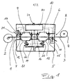
- the air-splicing device shown in Fig. 1 is adapted to splice-connecting two glass fiber roving strands such as the inner trailing strand 1 of a first glass fiber roving bobbin 2 to the outer trailing strand 3 of a second glass fiber roving bobbin 4. It comprises a housing 5 having a strand channel 6 which is open at its two opposing ends, i.e. the first end 7 and the second end 8, such that said first strand 1 and said second strand 3 can pass straight through said strand channel 6.
- the strand channel 6 receives a first splice chamber 9 and a second splice chamber 10 which are arranged side-by-side with a distance of about 5 cm.
- Air supply ducts 11 and 12 run into the first splice chamber 9 and a second splice chamber 10 respectively which air ducts are connectable to a typical pressurized air source (not shown).
- the strand channel receives four strand clamps namely a first outer strand clamp 13 and a first inner strand clamp 14 which are arranged pair-wise on either side of the first splice chamber 9 and a second outer strand clamp 15 and a second inner strand clamp 16 which are arranged pair-wise on either side of the second splice chamber 10.
- a first outer strand clamp 13 and a first inner strand clamp 14 which are arranged pair-wise on either side of the first splice chamber 9
- a second outer strand clamp 15 and a second inner strand clamp 16 which are arranged pair-wise on either side of the second splice chamber 10.
- Each of the strand clamps is adapted to fix both roving strands 1 and 3 which are fixed by the strand clamps in a parallel alignment immediately next to each other.
- the strand channel 6 receives two strand cutters namely a first strand cutter 17 being arranged next to and outside of the first outer strand clamp 13 and a second strand cutter 18 being arranged next to and outside of the second outer strand clamp 15.
- the air-splicing device comprises a control unit 23 with a memory having stored at least one splicing programme controlling the actuating of individual mechanical components of the air-splicing device such as the four strand clamps 13 to 16, the two strand cutters 17 and 18 and a first valve 19 and a second valve 20 arranged in the first air supply duct 11 and the second air supply duct 12 respectively.
- the control unit 23 reflecting the particular splice programme stored in the memory thereof, positively actuates all four strand clamps 13, 14, 15, and 16, the fist valve 19 and the second valve 20, as well as the first strand cutter 17 and the second strand cutter 18.
- the scheme being as follows:
- the splicing programme is triggered by pressing the switch 24 which may be provided in the region of a grip of the device.
- the fist pair of strand clamps i.e. the first outer strand clamp 13 and the first inner strand clamp 14 are actuated to engage both strands and to fix same, in the region of the first splice chamber 9, in a parallel alignment immediately next to each other.
- the valve 19 is opened to launch feeding pressurized air into the first splice chamber 9.
- the second pair of strand clamps i.e.
- the second outer strand clamp 15 and the second inner strand clamp 16 are actuated to engage both strands and to fix same, in the region of the second splice chamber 10, in a parallel alignment immediately next to each other.
- the valve 20 is opened to launch feeding pressurized air into the second splice chamber 10.
- the first strand cutter 17 is actuated to cut off the protruding end section 21 of the outer trailing strand 3 of the second glass fiber roving bobbin 4.
- feeding pressurized air to the second splice chamber 10 is terminated.
- the second strand cutter 18 is actuated to cut off the protruding end section 22 of the inner trailing strand 1 of the first glass fiber roving bobbin 2.
- both strand cutters 17 and 18 are deactivated.
- all four strand clamps 13, 14, 15, and 16 are deactivated. Now the splicing process cycle has finished and the two roving strands 1 and 3 are splice connected.
- the above described process is just an example which is not binding and from which an expert may deviate in many regards.
- the first and the second pair of strand clamps may rather be actuated simultaneously instead of consecutively and/or may be deactivated rather consecutively instead of simultaneously.
- the first and second strand cutters may rather be actuated simultaneously (after termination of feeding pressurized air to the second splice chamber 10) instead of consecutively and/or may be deactivated rather consecutively instead of simultaneously.
- the strand clamps need not to be of a type requiring individual positive actuation and deactivation but may rather be of a type that fixes the respective strand, upon inserting same into the clamp, without further e.g. by some friction.
Abstract
Description
- The present invention relates to an air-splicing device for splice-connecting two glass fiber roving strands. In particular, the present invention may relate to a hand-held air-splicing device for said application.
- There are available on the market various air-splicing devices for knot-free joining of filament yarns such as the AirSplicer™-17-2 and the AirSplicer™-40-2, both of Heberlein Fiber Technology, Inc., 9630 Wattwil (CH). Whereas glass fiber rovings are mentioned as a possible application of the AirSplicer™-40-2, the results that may be achieved so far are not satisfactory. In fact, tests have revealed that the splice joint of two glass roving strands may be of poor quality in the terms of strength; in a typical application the strength of the splice joint was tested to be only about 35% of the strength of the regular roving strands.
- In addition to the prior art discussed above, there are various patent publications relating to air-splicing devices for splice-connecting threaded filament yarns. Typically, the respective devices comprise one splice chamber similar as it applies to the above mentioned prior art devices. However, there are also disclosed air-splicing devices having two splice chambers arranged in series (e.g.
US 4292796 ,GB 956992 DE 4226025 ). But again, in spite of glass fiber filament yarns being mentioned in German Letters patent4226025 , these devices do not perform well in glass fiber rovings related applications. - In view of the prior art discussed above, the present invention aims at providing for an air-splicing device, such as a hand-held air-splicing device, particularly suited for splice-connecting two glass fiber roving strands. Similarly, the present invention aims at providing for a process of splice-connecting two glass fiber roving strands by making use of such an air-splicing device, which process results in an improved quality of splice joints in splice-connecting of glass fiber roving strands.
- In accordance with the present invention the object set out above is achieved by an air-splicing device for splice-connecting two glass fiber roving strands defined in detail in claim 1. Similarly, the above-identified object is achieved by a process of splice-connecting two glass fiber roving strands defined in detail in
claim 13. - Accordingly two of the key features of the present invention which act together with the remaining features of the respective claimed combination are that, in the strand channel, two splice chambers are provided side by side with at least one strand clamp in-between which splice chambers are capable of being fed by pressurized air independently of each other. In contrast to what is taught in the above-mentioned references relating to air-splicing devices with two splice chambers, the two splice chambers of the air-splicing device of the instant invention are not fed simultaneously with pressurized air. Rather the two splice chambers are fed with pressurized air in a timely offset manner. This might even include that the second splice chamber is not launched before feeding of the first splice chamber with pressurized air has been terminated; but this is not necessary, since rather there may be (and typically will be) to some degree an overlapping in the feeding of pressurized air to the first and the second splice chamber. For typical applications the time lag between launching the first splice chamber and the second splice chamber may be about 3 seconds or more. Very good results have been achieved by a time lag of 5 seconds.
- Experiments made with the air-splicing device of the present invention have shown that by making use of said device and/or applying the process of the present invention, splice joints of glass fiber roving strands can be made the average value of tensile strength of the splice being close to or even higher than the tensile strength usually measured at regular strands without splice. This is a quite surprising result in consideration that application of standard air-splicing devices presently on the market result in a fairly poor quality of the splice joint as set out above.
- According to a first preferred embodiment of the present invention there may be a distance between said two splice chambers of about 3 to 6 cm, preferably between about 4 and 5 cm. Best quality results in typical glass fiber roving splicing applications have been achieved with thus dimensioned air-splicing devices according to the invention.
- A second preferred embodiment of the inventive air-splicing device is characterized in that said two strand cutters are located on either side outside of said two outer strand clamps. With other words, the two outer strand clamps are preferably arranged between the two strand cutters. Again this is quite surprising because the strand clamps fix both roving strands in the respective splice chamber on either side thereof which, in consideration of the prior art teaching, would have to be regarded rather detrimental for the quality of the splice joint.
- According to a still further preferred embodiment of the present invention the air-splicing device comprises exactly four strand clamps two of which are arranged pair-wise on either side of the first splice chamber and the other two of which are arranged pair-wise on either side of the second splice chamber. Thus there are provided, in this particular embodiment, two outer strand clamps and two inner strand clamps, wherein there may be preferably a distance of about 3 to 5 cm between the said two inner strand clamps. Preferably, each of the strand clamps of this embodiment is adapted to fix both roving strands which are fixed by the strand clamps in an essentially parallel alignment next to each other. This, again, is a significant difference as compared with typical prior art air-splicing devices in which the two filaments cross each other in about the middle of the splice chamber but are spaced from each other at both edges thereof, to which end both strands are fixed on either side of the splice chamber by individual strand clamps spaced apart with respect to each other.
- In a still further preferred embodiment the air-splicing device further comprises a control unit with a memory having stored at least one splicing programme controlling the individual mechanical components of the air-splicing device, said splicing programme
- actuating at least one strand clamp located outside of said first splice chamber and at least one strand clamp located between the two splice chambers for fixing both glass fiber roving strands in the region of the first splice chamber,
- feeding pressurised air to the first splice chamber,
- actuating at least one strand clamp located outside of said second splice chamber and at least one strand clamp located between the two splice chambers for fixing both glass fiber roving strands in the region of the second splice chamber,
- feeding pressurised air to the second splice chamber timely offset with respect to said feeding of pressurized air to the first splice chamber,
- actuating both strand cutters for cutting off the free ends of both glass fiber roving strands.
- The duration of the individual feeding of pressurized air to the splice chambers, the time lag between initializing the feeding of pressurized air to the first and the second splice chamber respectively, and any other appropriate parameter of the splicing programme can be stored in the memory of the splicing unit depending on the individual splicing application. E.g., the control unit, in response to said stored splicing programme, may initiate feeding pressurised air to the second splice chamber only after feeding pressurised air to the first splice chamber has been terminated.
- Whereas, depending on the individual time lag between initializing the feeding of pressurized air to the first and the second splice chamber respectively, the strand clamps fixing the two roving strands in the region of the second splice chamber may be actuated timely offset only after actuating the strand clamps fixing the two roving strands in the region of the first splice chamber, the control unit, in response the individal stored splicing programme, may actuate all of the strand clamps simultaneously for fixing both glass fiber roving strands in the region of both splice chambers, before initiating feeding pressurised air to the first splice chamber.
- Similar applies to actuation of the strand cutters. Whereas, depending on the individual time lag between the feeding of pressurized air to the first and the second splice chamber respectively, the strand cutter next to the first splice chamber may be actuated (before or after termination of feeding pressurized air to the second splice chamber) earlier than the strand cutter next to the second splice chamber, the control unit, in response the individual stored splicing programme, may actuate both strand cutters simultaneously only after termination of feeding pressurized air to the second splice chamber.
- According to another aspect of the present invention a process of splice-connecting two glass fiber roving strands by making use of an inventive air-splicing device discussed above comprises the following steps:
- introducing the two glass fiber roving strands into the strand channel;
- fixing the two glass fiber roving strands in the region of the first splice chamber by at least two strand clamps arranged at either side of the first splice chamber;
- feeding pressurised air to said first splice chamber;
- fixing the two glass fiber roving strands in the region of the second splice chamber by at least two strand clamps arranged at either side of the second splice chamber;
- feeding pressurised air to said second splice chamber timely offset with respect to said feeding pressurised air to said first splice chamber;
- cutting off the free ends of the strands by actuating the strand cutters.
- In order to avoid repetitions reference is made to the above explanations of the inventive air-splicing device which explanations also highlight the advantages of the method set out above. In view of the particular relevance thereof, it is to be mentioned at this point only that most preferably the two roving strands are inserted into the strand channel in an essentially parallel alignment next to each other.
- Just by way of precaution it shall be mentioned that the strand clamps need not to be clamps which allow positive actuation for a predetermined time for engaging the strands and releasing same after actuation has been terminated. Rather, the strand clamps may be of a type that fixes the respective strand, upon inserting same into the clamp, without further e.g. by some friction. This is particularly useful if the device is designed for hand-held operation since it allows introducing, with only one hand, the two strands one after the other into the strand channel and the strand clamps located therein while the operator holds the device with his other hand.
- In the following, a preferred embodiment of the present invention is described in detail, making reference to the attached drawing in which
-
Fig. 1 shows a schematic cut through a preferred air-splicing device according to the present invention and -
Fig. 2 shows a diagram illustrating a process to be perfomed by said device. - The air-splicing device shown in
Fig. 1 is adapted to splice-connecting two glass fiber roving strands such as the inner trailing strand 1 of a first glassfiber roving bobbin 2 to the outertrailing strand 3 of a second glassfiber roving bobbin 4. It comprises ahousing 5 having astrand channel 6 which is open at its two opposing ends, i.e. thefirst end 7 and thesecond end 8, such that said first strand 1 and saidsecond strand 3 can pass straight through saidstrand channel 6. - The
strand channel 6 receives afirst splice chamber 9 and asecond splice chamber 10 which are arranged side-by-side with a distance of about 5 cm.Air supply ducts first splice chamber 9 and asecond splice chamber 10 respectively which air ducts are connectable to a typical pressurized air source (not shown). - The strand channel receives four strand clamps namely a first
outer strand clamp 13 and a firstinner strand clamp 14 which are arranged pair-wise on either side of thefirst splice chamber 9 and a secondouter strand clamp 15 and a secondinner strand clamp 16 which are arranged pair-wise on either side of thesecond splice chamber 10. Thus there are provided twoouter strand clamps inner strand clamps strands 1 and 3 which are fixed by the strand clamps in a parallel alignment immediately next to each other. - Further, the
strand channel 6 receives two strand cutters namely afirst strand cutter 17 being arranged next to and outside of the firstouter strand clamp 13 and asecond strand cutter 18 being arranged next to and outside of the secondouter strand clamp 15. - Still further the air-splicing device comprises a
control unit 23 with a memory having stored at least one splicing programme controlling the actuating of individual mechanical components of the air-splicing device such as the fourstrand clamps 13 to 16, the twostrand cutters first valve 19 and asecond valve 20 arranged in the firstair supply duct 11 and the secondair supply duct 12 respectively. As shown in more detail inFig. 2 , thecontrol unit 23, reflecting the particular splice programme stored in the memory thereof, positively actuates all four strand clamps 13, 14, 15, and 16, thefist valve 19 and thesecond valve 20, as well as thefirst strand cutter 17 and thesecond strand cutter 18. The scheme being as follows: - After having inserted both
strands 1 and 3 into thestrand channel 6, the splicing programme is triggered by pressing theswitch 24 which may be provided in the region of a grip of the device. At the time t1 the fist pair of strand clamps, i.e. the firstouter strand clamp 13 and the firstinner strand clamp 14, are actuated to engage both strands and to fix same, in the region of thefirst splice chamber 9, in a parallel alignment immediately next to each other. At the time t2 thevalve 19 is opened to launch feeding pressurized air into thefirst splice chamber 9. At the time t3 the second pair of strand clamps, i.e. the secondouter strand clamp 15 and the secondinner strand clamp 16, are actuated to engage both strands and to fix same, in the region of thesecond splice chamber 10, in a parallel alignment immediately next to each other. At the time t4 thevalve 20 is opened to launch feeding pressurized air into thesecond splice chamber 10. At the time t5 feeding pressurized air to thefirst splice chamber 9 is terminated. At the time t6 thefirst strand cutter 17 is actuated to cut off theprotruding end section 21 of the outer trailingstrand 3 of the second glass fiberroving bobbin 4. At the time t7 feeding pressurized air to thesecond splice chamber 10 is terminated. At the time t8 thesecond strand cutter 18 is actuated to cut off the protruding end section 22 of the inner trailing strand 1 of the first glass fiberroving bobbin 2. At the time t9 bothstrand cutters roving strands 1 and 3 are splice connected. - Apparently, the above described process is just an example which is not binding and from which an expert may deviate in many regards. E.g., the first and the second pair of strand clamps may rather be actuated simultaneously instead of consecutively and/or may be deactivated rather consecutively instead of simultaneously. Similarly the first and second strand cutters may rather be actuated simultaneously (after termination of feeding pressurized air to the second splice chamber 10) instead of consecutively and/or may be deactivated rather consecutively instead of simultaneously. And still further, the strand clamps, as mentioned earlier, need not to be of a type requiring individual positive actuation and deactivation but may rather be of a type that fixes the respective strand, upon inserting same into the clamp, without further e.g. by some friction.
Claims (14)
- Air-splicing device for splice-connecting two glass-fiber roving strands (1, 3), comprising- a strand channel (6) open at its two opposing ends (7, 8),- two splice chambers (9, 10) arranged side-by-side in said strand channel, said first and second splice chambers being feedable with pressurised air independently of each other,- at least three strand clamps (13, 14, 15, 16) two of which are outer strand clamps (13, 15) arranged at either side outside of said two splice chambers and at least one of which is an inner strand clamp (14, 16) arranged between said two splice chambers,- two strand cutters (17, 18) arranged at the opposite ends of the strand channel.
- Air-splicing device according to claim 1, wherein there is a distance of 3 to 6 cm between said two splice chambers (9, 10).
- Air-splicing device according to claim 2, wherein there is a distance of 4 to 5 cm between said two splice chambers (9, 10).
- Air-splicing device according to one of the claims 1 to 3, wherein said two strand cutters (17, 18) are located on either side outside of said two outer strand clamps (13, 15).
- Air-splicing device according to one of the preceding claims, comprising exactly four strand clamps (13, 14, 15, 16) two of which are arranged pair-wise on either side of the first splice chamber (9) and the other two of which are arranged pair-wise on either side of the second splice chamber (10).
- Air-splicing device according to claim 5, wherein there is a distance of 3 to 5 cm between those two inner strand clamps (14, 16) which are arranged between the two splice chambers (9, 10).
- Air-splicing device according to one of the claims 1 to 6, wherein each of the strand clamps (13, 14, 15, 16) is adapted to fix both roving strands (1, 3) in an essentially parallel alignment next to each other.
- Air-splicing device according to one of the preceding claims further comprising a control unit (23) with a memory having stored at least one splicing programme controlling the individual mechanical components of the air-splicing device, said splicing programme- actuating at least one strand clamp (13) located outside of said first splice chamber (9) and at least one strand clamp (14) located between the two splice chambers (9, 10) for fixing both glass fiber roving strands (1, 3) in the region of the first splice chamber,- feeding pressurised air to the first splice chamber,- actuating at least one strand clamp (15) located outside of said second splice chamber (10) and at least one strand clamp (16) located between the two splice chambers (9, 10) for fixing both glass fiber roving strands in the region of the second splice chamber,- feeding pressurised air to the second splice chamber timely offset with respect to said feeding of pressurized air to the first splice chamber,- actuating both strand cutters (17, 18) for cutting off the free ends of both glass fiber roving strands (1, 3).
- Air-splicing device according to claim 8, wherein the control unit (23), in response to said stored splicing programme, initiates feeding of the second splice chamber (10) with pressurised air only after feeding of the first splice chamber (9) with pressurised air has been terminated.
- Air-splicing device according to claim 8 or claim 9, wherein the control unit (23), in response to said stored splicing programme, actuates all of the strand clamps (13, 14, 15, 16) simultaneously for fixing both glass fiber roving strands (1, 3) in the region of both splice chambers (9, 10), before initiating feeding pressurised air to the first splice chamber (9).
- Air-splicing device according to one of the claims 8 to 10, wherein the control unit (23), in response to said stored splicing programme, actuates at least one of the strand cutters (17, 18) only after termination of feeding pressurised air to said second splice chamber (10).
- Air-splicing device according to claim 11, wherein the control unit (23), in response to said stored splicing programme, actuates both strand cutters (17, 18) only after termination of feeding pressurised air to said second splice chamber (10).
- Process of splice-connecting two glass fiber roving strands by making use of an air-splicing device according to claim 1, the process comprising the following steps:- introducing the two glass fiber roving strands (1, 3) into the strand channel (6);- fixing the two glass fiber roving strands in the region of the first splice chamber (9) by at least two strand clamps (13, 14) arranged at either side of the first splice chamber;- feeding pressurised air to said first splice chamber;- fixing the two glass fiber roving strands (1, 3) in the region of the second splice chamber (10) by at least two strand clamps (15, 16) arranged at either side of the second splice chamber (10);- feeding pressurised air to said second splice chamber (10) timely offset with respect to said feeding pressurised air to said first splice chamber;- cutting off the free ends of the strand by actuating the strand cutters (17, 18).
- Process according to claim 13, wherein the two glass fiber roving strands (1, 3) are inserted into the strand channel (6) in an essentially parallel alignment next to each other.
Priority Applications (4)
| Application Number | Priority Date | Filing Date | Title |
|---|---|---|---|
| DE602007006678T DE602007006678D1 (en) | 2007-12-04 | 2007-12-04 | An air splicer for splice bonding two fiberglass roving bundles and method for splicing the same |
| EP07023410A EP2067730B1 (en) | 2007-12-04 | 2007-12-04 | Air splicing device for splice-connecting two glass fiber roving strands and process of splice-connecting the same |
| AT07023410T ATE468293T1 (en) | 2007-12-04 | 2007-12-04 | AIR SPLICE DEVICE FOR SPLICING TWO ROVING BUNDLES MADE OF GLASS FIBERS AND METHOD FOR SPLICING THE SAME |
| US12/328,470 US7870714B2 (en) | 2007-12-04 | 2008-12-04 | Air-splicing device for splice-connecting two glass fiber roving strands and process of splice-connecting same |
Applications Claiming Priority (1)
| Application Number | Priority Date | Filing Date | Title |
|---|---|---|---|
| EP07023410A EP2067730B1 (en) | 2007-12-04 | 2007-12-04 | Air splicing device for splice-connecting two glass fiber roving strands and process of splice-connecting the same |
Publications (2)
| Publication Number | Publication Date |
|---|---|
| EP2067730A1 EP2067730A1 (en) | 2009-06-10 |
| EP2067730B1 true EP2067730B1 (en) | 2010-05-19 |
Family
ID=39361302
Family Applications (1)
| Application Number | Title | Priority Date | Filing Date |
|---|---|---|---|
| EP07023410A Active EP2067730B1 (en) | 2007-12-04 | 2007-12-04 | Air splicing device for splice-connecting two glass fiber roving strands and process of splice-connecting the same |
Country Status (4)
| Country | Link |
|---|---|
| US (1) | US7870714B2 (en) |
| EP (1) | EP2067730B1 (en) |
| AT (1) | ATE468293T1 (en) |
| DE (1) | DE602007006678D1 (en) |
Cited By (1)
| Publication number | Priority date | Publication date | Assignee | Title |
|---|---|---|---|---|
| EP3738913A1 (en) | 2019-05-14 | 2020-11-18 | Cetex Institut gGmbH | Method and device for continuous processing of single or multiple rovings |
Families Citing this family (8)
| Publication number | Priority date | Publication date | Assignee | Title |
|---|---|---|---|---|
| CN102472869A (en) * | 2009-07-29 | 2012-05-23 | Ppg工业俄亥俄公司 | Spliced fiber glass rovings and methods and systems for splicing fiber glass rovings |
| US9884740B2 (en) * | 2009-11-09 | 2018-02-06 | Toray Industries, Inc. | Fiber bundle with pieced part, process for producing same, and process for producing carbon fiber |
| WO2011106523A1 (en) * | 2010-02-26 | 2011-09-01 | Zoltek Companies, Inc. | Spliced carbon fiber tow and method and apparatus for splicing carbon fiber tow |
| CN102212908B (en) * | 2011-06-07 | 2013-07-24 | 无锡市三达纺配有限公司 | Upper shell of air splicer with reliable twisting |
| RU2473723C2 (en) * | 2011-08-08 | 2013-01-27 | Закрытое Акционерное Общество "Препрег - Современные Композиционные Материалы" | Unit and method of flattening harness and the flattening plant |
| CN102330231A (en) * | 2011-09-24 | 2012-01-25 | 无锡星卫星机械科技有限公司 | Twisting and knotting machine for wool top joints |
| CN108409164A (en) * | 2017-02-09 | 2018-08-17 | 巨石集团有限公司 | A kind of glass fiber bundle knotting method and splicing glass fiber bundle |
| KR102067355B1 (en) * | 2019-01-02 | 2020-02-11 | 김일열 | Air splicing device |
Family Cites Families (6)
| Publication number | Priority date | Publication date | Assignee | Title |
|---|---|---|---|---|
| BE625194A (en) | 1961-11-23 | |||
| US4002013A (en) * | 1976-01-13 | 1977-01-11 | E. I. Du Pont De Nemours And Company | Process and apparatus |
| JPS55106968A (en) | 1979-02-09 | 1980-08-16 | Murata Mach Ltd | Pneumatic type thread connector |
| DE4226025C2 (en) | 1991-09-19 | 1996-10-24 | Akzo Nobel Nv | Device for splicing multifilament yarns |
| EP1420091B1 (en) * | 2001-06-12 | 2011-10-05 | Mitsubishi Rayon Co., Ltd. | Production device for carbon fibers and production method therefor |
| US6907721B2 (en) * | 2002-12-19 | 2005-06-21 | Invista North America, S.A.R.L. | Spliced yarn and method for forming the same |
-
2007
- 2007-12-04 AT AT07023410T patent/ATE468293T1/en not_active IP Right Cessation
- 2007-12-04 DE DE602007006678T patent/DE602007006678D1/en active Active
- 2007-12-04 EP EP07023410A patent/EP2067730B1/en active Active
-
2008
- 2008-12-04 US US12/328,470 patent/US7870714B2/en active Active
Cited By (3)
| Publication number | Priority date | Publication date | Assignee | Title |
|---|---|---|---|---|
| EP3738913A1 (en) | 2019-05-14 | 2020-11-18 | Cetex Institut gGmbH | Method and device for continuous processing of single or multiple rovings |
| DE102019112554A1 (en) * | 2019-05-14 | 2020-11-19 | Cetex Institut gGmbH | Method and device for the continuous processing of several rovings |
| DE102019112554B4 (en) * | 2019-05-14 | 2020-12-17 | Cetex Institut gGmbH | Method and device for the continuous processing of several rovings |
Also Published As
| Publication number | Publication date |
|---|---|
| DE602007006678D1 (en) | 2010-07-01 |
| US7870714B2 (en) | 2011-01-18 |
| EP2067730A1 (en) | 2009-06-10 |
| US20090139197A1 (en) | 2009-06-04 |
| ATE468293T1 (en) | 2010-06-15 |
Similar Documents
| Publication | Publication Date | Title |
|---|---|---|
| EP2067730B1 (en) | Air splicing device for splice-connecting two glass fiber roving strands and process of splice-connecting the same | |
| EP2126617B1 (en) | Retention and rotation clamp assembly for use with an angled optical fiber cleaver | |
| US8505271B2 (en) | Spliced fiber glass rovings and methods and systems for splicing fiber glass rovings | |
| US8254743B2 (en) | Optical fiber cable holder, fusion splicer including the holder, and fusion splicing method using the holder | |
| CN101111789B (en) | Optical fibre cleaving device | |
| EP0507585B1 (en) | Optical fibre splicing | |
| US20160306126A1 (en) | Tool for preparing a cable for termination | |
| US5195157A (en) | Optical fibre splicing | |
| JPH0151432B2 (en) | ||
| JP4630266B2 (en) | Optical fiber cord holder, method of manufacturing optical fiber cord with connector using the same, and fusion splicer | |
| JP2008181004A (en) | Ferrule holder | |
| US6904226B2 (en) | Apparatus and method for preparing a coated optical fiber | |
| JPS6211322B2 (en) | ||
| US20010003241A1 (en) | Method for the pneumatic splicing of threads or yarns containing an elastomer and device for performing said splicing | |
| EP1344739B1 (en) | Splicing method of core yarns and automatic winder comprising core yarn splicing device | |
| JPS61211017A (en) | Method of combining section and combination | |
| JP4752730B2 (en) | Optical fiber heating reinforcement processing apparatus and optical fiber fusion splicing apparatus | |
| WO1998042608A1 (en) | Pneumatic yarn splicer | |
| JP4268892B2 (en) | Optical fiber coupler manufacturing method and optical fiber coupler manufacturing apparatus | |
| US6561700B1 (en) | Fiber optic cable splice apparatus and method | |
| US20040232189A1 (en) | Device and method for separating at least one optical fiber | |
| JP3134317U (en) | Connector assembly tool | |
| JP2006053399A (en) | Optical fiber coupler manufacturing apparatus | |
| KR20030061485A (en) | System for manufacture optical fiber couplers | |
| JPS5975214A (en) | Reinforcing method of optical fiber arc welding connection part |
Legal Events
| Date | Code | Title | Description |
|---|---|---|---|
| PUAI | Public reference made under article 153(3) epc to a published international application that has entered the european phase |
Free format text: ORIGINAL CODE: 0009012 |
|
| AK | Designated contracting states |
Kind code of ref document: A1 Designated state(s): AT BE BG CH CY CZ DE DK EE ES FI FR GB GR HU IE IS IT LI LT LU LV MC MT NL PL PT RO SE SI SK TR |
|
| AX | Request for extension of the european patent |
Extension state: AL BA HR MK RS |
|
| 17P | Request for examination filed |
Effective date: 20090708 |
|
| RIN1 | Information on inventor provided before grant (corrected) |
Inventor name: SIKULA, DUSAN Inventor name: SABO, FRANTISEK Inventor name: HAJTMAN, MAREK |
|
| GRAP | Despatch of communication of intention to grant a patent |
Free format text: ORIGINAL CODE: EPIDOSNIGR1 |
|
| AKX | Designation fees paid |
Designated state(s): AT BE BG CH CY CZ DE DK EE ES FI FR GB GR HU IE IS IT LI LT LU LV MC MT NL PL PT RO SE SI SK TR |
|
| GRAS | Grant fee paid |
Free format text: ORIGINAL CODE: EPIDOSNIGR3 |
|
| GRAA | (expected) grant |
Free format text: ORIGINAL CODE: 0009210 |
|
| AK | Designated contracting states |
Kind code of ref document: B1 Designated state(s): AT BE BG CH CY CZ DE DK EE ES FI FR GB GR HU IE IS IT LI LT LU LV MC MT NL PL PT RO SE SI SK TR |
|
| REG | Reference to a national code |
Ref country code: GB Ref legal event code: FG4D |
|
| REG | Reference to a national code |
Ref country code: CH Ref legal event code: EP |
|
| REG | Reference to a national code |
Ref country code: IE Ref legal event code: FG4D |
|
| REF | Corresponds to: |
Ref document number: 602007006678 Country of ref document: DE Date of ref document: 20100701 Kind code of ref document: P |
|
| REG | Reference to a national code |
Ref country code: NL Ref legal event code: T3 |
|
| LTIE | Lt: invalidation of european patent or patent extension |
Effective date: 20100519 |
|
| PG25 | Lapsed in a contracting state [announced via postgrant information from national office to epo] |
Ref country code: SE Free format text: LAPSE BECAUSE OF FAILURE TO SUBMIT A TRANSLATION OF THE DESCRIPTION OR TO PAY THE FEE WITHIN THE PRESCRIBED TIME-LIMIT Effective date: 20100519 Ref country code: LT Free format text: LAPSE BECAUSE OF FAILURE TO SUBMIT A TRANSLATION OF THE DESCRIPTION OR TO PAY THE FEE WITHIN THE PRESCRIBED TIME-LIMIT Effective date: 20100519 Ref country code: ES Free format text: LAPSE BECAUSE OF FAILURE TO SUBMIT A TRANSLATION OF THE DESCRIPTION OR TO PAY THE FEE WITHIN THE PRESCRIBED TIME-LIMIT Effective date: 20100830 |
|
| REG | Reference to a national code |
Ref country code: SK Ref legal event code: T3 Ref document number: E 7648 Country of ref document: SK |
|
| PG25 | Lapsed in a contracting state [announced via postgrant information from national office to epo] |
Ref country code: IS Free format text: LAPSE BECAUSE OF FAILURE TO SUBMIT A TRANSLATION OF THE DESCRIPTION OR TO PAY THE FEE WITHIN THE PRESCRIBED TIME-LIMIT Effective date: 20100919 Ref country code: AT Free format text: LAPSE BECAUSE OF FAILURE TO SUBMIT A TRANSLATION OF THE DESCRIPTION OR TO PAY THE FEE WITHIN THE PRESCRIBED TIME-LIMIT Effective date: 20100519 Ref country code: SI Free format text: LAPSE BECAUSE OF FAILURE TO SUBMIT A TRANSLATION OF THE DESCRIPTION OR TO PAY THE FEE WITHIN THE PRESCRIBED TIME-LIMIT Effective date: 20100519 |
|
| PG25 | Lapsed in a contracting state [announced via postgrant information from national office to epo] |
Ref country code: CY Free format text: LAPSE BECAUSE OF FAILURE TO SUBMIT A TRANSLATION OF THE DESCRIPTION OR TO PAY THE FEE WITHIN THE PRESCRIBED TIME-LIMIT Effective date: 20100609 Ref country code: PL Free format text: LAPSE BECAUSE OF FAILURE TO SUBMIT A TRANSLATION OF THE DESCRIPTION OR TO PAY THE FEE WITHIN THE PRESCRIBED TIME-LIMIT Effective date: 20100519 |
|
| PG25 | Lapsed in a contracting state [announced via postgrant information from national office to epo] |
Ref country code: PT Free format text: LAPSE BECAUSE OF FAILURE TO SUBMIT A TRANSLATION OF THE DESCRIPTION OR TO PAY THE FEE WITHIN THE PRESCRIBED TIME-LIMIT Effective date: 20100920 Ref country code: GR Free format text: LAPSE BECAUSE OF FAILURE TO SUBMIT A TRANSLATION OF THE DESCRIPTION OR TO PAY THE FEE WITHIN THE PRESCRIBED TIME-LIMIT Effective date: 20100820 Ref country code: EE Free format text: LAPSE BECAUSE OF FAILURE TO SUBMIT A TRANSLATION OF THE DESCRIPTION OR TO PAY THE FEE WITHIN THE PRESCRIBED TIME-LIMIT Effective date: 20100519 Ref country code: DK Free format text: LAPSE BECAUSE OF FAILURE TO SUBMIT A TRANSLATION OF THE DESCRIPTION OR TO PAY THE FEE WITHIN THE PRESCRIBED TIME-LIMIT Effective date: 20100519 |
|
| PG25 | Lapsed in a contracting state [announced via postgrant information from national office to epo] |
Ref country code: CZ Free format text: LAPSE BECAUSE OF FAILURE TO SUBMIT A TRANSLATION OF THE DESCRIPTION OR TO PAY THE FEE WITHIN THE PRESCRIBED TIME-LIMIT Effective date: 20100519 Ref country code: RO Free format text: LAPSE BECAUSE OF FAILURE TO SUBMIT A TRANSLATION OF THE DESCRIPTION OR TO PAY THE FEE WITHIN THE PRESCRIBED TIME-LIMIT Effective date: 20100519 |
|
| PLBE | No opposition filed within time limit |
Free format text: ORIGINAL CODE: 0009261 |
|
| STAA | Information on the status of an ep patent application or granted ep patent |
Free format text: STATUS: NO OPPOSITION FILED WITHIN TIME LIMIT |
|
| PGFP | Annual fee paid to national office [announced via postgrant information from national office to epo] |
Ref country code: LV Payment date: 20101123 Year of fee payment: 4 |
|
| 26N | No opposition filed |
Effective date: 20110222 |
|
| REG | Reference to a national code |
Ref country code: DE Ref legal event code: R097 Ref document number: 602007006678 Country of ref document: DE Effective date: 20110221 |
|
| PG25 | Lapsed in a contracting state [announced via postgrant information from national office to epo] |
Ref country code: MC Free format text: LAPSE BECAUSE OF NON-PAYMENT OF DUE FEES Effective date: 20101231 |
|
| PG25 | Lapsed in a contracting state [announced via postgrant information from national office to epo] |
Ref country code: IE Free format text: LAPSE BECAUSE OF NON-PAYMENT OF DUE FEES Effective date: 20101204 |
|
| PG25 | Lapsed in a contracting state [announced via postgrant information from national office to epo] |
Ref country code: IT Free format text: LAPSE BECAUSE OF NON-PAYMENT OF DUE FEES Effective date: 20101204 Ref country code: MT Free format text: LAPSE BECAUSE OF FAILURE TO SUBMIT A TRANSLATION OF THE DESCRIPTION OR TO PAY THE FEE WITHIN THE PRESCRIBED TIME-LIMIT Effective date: 20100519 |
|
| REG | Reference to a national code |
Ref country code: CH Ref legal event code: PL |
|
| PG25 | Lapsed in a contracting state [announced via postgrant information from national office to epo] |
Ref country code: LV Free format text: LAPSE BECAUSE OF NON-PAYMENT OF DUE FEES Effective date: 20111204 |
|
| PG25 | Lapsed in a contracting state [announced via postgrant information from national office to epo] |
Ref country code: BG Free format text: LAPSE BECAUSE OF FAILURE TO SUBMIT A TRANSLATION OF THE DESCRIPTION OR TO PAY THE FEE WITHIN THE PRESCRIBED TIME-LIMIT Effective date: 20100519 Ref country code: LU Free format text: LAPSE BECAUSE OF NON-PAYMENT OF DUE FEES Effective date: 20101204 Ref country code: HU Free format text: LAPSE BECAUSE OF FAILURE TO SUBMIT A TRANSLATION OF THE DESCRIPTION OR TO PAY THE FEE WITHIN THE PRESCRIBED TIME-LIMIT Effective date: 20101120 |
|
| PG25 | Lapsed in a contracting state [announced via postgrant information from national office to epo] |
Ref country code: CH Free format text: LAPSE BECAUSE OF NON-PAYMENT OF DUE FEES Effective date: 20111231 Ref country code: LI Free format text: LAPSE BECAUSE OF NON-PAYMENT OF DUE FEES Effective date: 20111231 |
|
| PG25 | Lapsed in a contracting state [announced via postgrant information from national office to epo] |
Ref country code: BG Free format text: LAPSE BECAUSE OF FAILURE TO SUBMIT A TRANSLATION OF THE DESCRIPTION OR TO PAY THE FEE WITHIN THE PRESCRIBED TIME-LIMIT Effective date: 20100819 |
|
| PGFP | Annual fee paid to national office [announced via postgrant information from national office to epo] |
Ref country code: GB Payment date: 20131227 Year of fee payment: 7 |
|
| PGFP | Annual fee paid to national office [announced via postgrant information from national office to epo] |
Ref country code: IT Payment date: 20131220 Year of fee payment: 7 Ref country code: FI Payment date: 20131230 Year of fee payment: 7 Ref country code: TR Payment date: 20131127 Year of fee payment: 7 |
|
| PG25 | Lapsed in a contracting state [announced via postgrant information from national office to epo] |
Ref country code: FI Free format text: LAPSE BECAUSE OF NON-PAYMENT OF DUE FEES Effective date: 20141204 |
|
| GBPC | Gb: european patent ceased through non-payment of renewal fee |
Effective date: 20141204 |
|
| PG25 | Lapsed in a contracting state [announced via postgrant information from national office to epo] |
Ref country code: GB Free format text: LAPSE BECAUSE OF NON-PAYMENT OF DUE FEES Effective date: 20141204 |
|
| REG | Reference to a national code |
Ref country code: FR Ref legal event code: PLFP Year of fee payment: 9 |
|
| PG25 | Lapsed in a contracting state [announced via postgrant information from national office to epo] |
Ref country code: IT Free format text: LAPSE BECAUSE OF NON-PAYMENT OF DUE FEES Effective date: 20141204 |
|
| REG | Reference to a national code |
Ref country code: FR Ref legal event code: PLFP Year of fee payment: 10 |
|
| PG25 | Lapsed in a contracting state [announced via postgrant information from national office to epo] |
Ref country code: TR Free format text: LAPSE BECAUSE OF NON-PAYMENT OF DUE FEES Effective date: 20141204 |
|
| REG | Reference to a national code |
Ref country code: FR Ref legal event code: PLFP Year of fee payment: 11 |
|
| PGFP | Annual fee paid to national office [announced via postgrant information from national office to epo] |
Ref country code: BE Payment date: 20221227 Year of fee payment: 16 |
|
| PGFP | Annual fee paid to national office [announced via postgrant information from national office to epo] |
Ref country code: DE Payment date: 20221228 Year of fee payment: 16 |
|
| PGFP | Annual fee paid to national office [announced via postgrant information from national office to epo] |
Ref country code: SK Payment date: 20231120 Year of fee payment: 17 |
|
| PGFP | Annual fee paid to national office [announced via postgrant information from national office to epo] |
Ref country code: NL Payment date: 20231226 Year of fee payment: 17 Ref country code: FR Payment date: 20231227 Year of fee payment: 17 |
|
| PGFP | Annual fee paid to national office [announced via postgrant information from national office to epo] |
Ref country code: BE Payment date: 20231227 Year of fee payment: 17 |