EP2067696B1 - Actuation system for a lift assisting device and roller bearings used therein - Google Patents
Actuation system for a lift assisting device and roller bearings used therein Download PDFInfo
- Publication number
- EP2067696B1 EP2067696B1 EP08168716.2A EP08168716A EP2067696B1 EP 2067696 B1 EP2067696 B1 EP 2067696B1 EP 08168716 A EP08168716 A EP 08168716A EP 2067696 B1 EP2067696 B1 EP 2067696B1
- Authority
- EP
- European Patent Office
- Prior art keywords
- track
- actuation system
- assisting device
- coupled
- comprised
- Prior art date
- Legal status (The legal status is an assumption and is not a legal conclusion. Google has not performed a legal analysis and makes no representation as to the accuracy of the status listed.)
- Not-in-force
Links
- 238000000034 method Methods 0.000 claims description 10
- 229910001220 stainless steel Inorganic materials 0.000 claims description 10
- 239000010935 stainless steel Substances 0.000 claims description 10
- 229910000831 Steel Inorganic materials 0.000 claims description 9
- 239000010959 steel Substances 0.000 claims description 9
- -1 polytetrafluoroethylene Polymers 0.000 claims description 7
- 230000008569 process Effects 0.000 claims description 7
- RZVHIXYEVGDQDX-UHFFFAOYSA-N 9,10-anthraquinone Chemical group C1=CC=C2C(=O)C3=CC=CC=C3C(=O)C2=C1 RZVHIXYEVGDQDX-UHFFFAOYSA-N 0.000 claims description 6
- 229920000728 polyester Polymers 0.000 claims description 6
- 230000004044 response Effects 0.000 claims description 6
- 238000005121 nitriding Methods 0.000 claims description 5
- OKTJSMMVPCPJKN-UHFFFAOYSA-N Carbon Chemical compound [C] OKTJSMMVPCPJKN-UHFFFAOYSA-N 0.000 claims description 4
- 239000004593 Epoxy Substances 0.000 claims description 4
- JOYRKODLDBILNP-UHFFFAOYSA-N Ethyl urethane Chemical compound CCOC(N)=O JOYRKODLDBILNP-UHFFFAOYSA-N 0.000 claims description 4
- 239000004642 Polyimide Substances 0.000 claims description 4
- 238000005452 bending Methods 0.000 claims description 4
- 229910002804 graphite Inorganic materials 0.000 claims description 4
- 239000010439 graphite Substances 0.000 claims description 4
- ISWSIDIOOBJBQZ-UHFFFAOYSA-N phenol group Chemical group C1(=CC=CC=C1)O ISWSIDIOOBJBQZ-UHFFFAOYSA-N 0.000 claims description 4
- 229920001721 polyimide Polymers 0.000 claims description 4
- 229920001343 polytetrafluoroethylene Polymers 0.000 claims description 4
- 239000004810 polytetrafluoroethylene Substances 0.000 claims description 4
- 239000000805 composite resin Substances 0.000 claims description 2
- 230000008878 coupling Effects 0.000 claims description 2
- 238000010168 coupling process Methods 0.000 claims description 2
- 238000005859 coupling reaction Methods 0.000 claims description 2
- 239000004744 fabric Substances 0.000 claims description 2
- 239000000835 fiber Substances 0.000 claims description 2
- 229920000642 polymer Polymers 0.000 claims description 2
- 229920001187 thermosetting polymer Polymers 0.000 claims description 2
- 229910001213 440C Inorganic materials 0.000 description 5
- 230000007246 mechanism Effects 0.000 description 4
- 229920006362 Teflon® Polymers 0.000 description 3
- 230000000712 assembly Effects 0.000 description 3
- 238000000429 assembly Methods 0.000 description 3
- 239000004519 grease Substances 0.000 description 3
- 238000012423 maintenance Methods 0.000 description 3
- 238000005096 rolling process Methods 0.000 description 3
- 229920004943 Delrin® Polymers 0.000 description 2
- 238000005260 corrosion Methods 0.000 description 2
- 230000007797 corrosion Effects 0.000 description 2
- 239000000428 dust Substances 0.000 description 2
- 230000001050 lubricating effect Effects 0.000 description 2
- 239000000463 material Substances 0.000 description 2
- 238000004881 precipitation hardening Methods 0.000 description 2
- 239000011347 resin Substances 0.000 description 2
- 229920005989 resin Polymers 0.000 description 2
- 229910000984 420 stainless steel Inorganic materials 0.000 description 1
- 229920005123 Celcon® Polymers 0.000 description 1
- 239000004809 Teflon Substances 0.000 description 1
- RTAQQCXQSZGOHL-UHFFFAOYSA-N Titanium Chemical compound [Ti] RTAQQCXQSZGOHL-UHFFFAOYSA-N 0.000 description 1
- DHKHKXVYLBGOIT-UHFFFAOYSA-N acetaldehyde Diethyl Acetal Natural products CCOC(C)OCC DHKHKXVYLBGOIT-UHFFFAOYSA-N 0.000 description 1
- 230000004075 alteration Effects 0.000 description 1
- 230000009286 beneficial effect Effects 0.000 description 1
- 230000005540 biological transmission Effects 0.000 description 1
- 229910052793 cadmium Inorganic materials 0.000 description 1
- BDOSMKKIYDKNTQ-UHFFFAOYSA-N cadmium atom Chemical compound [Cd] BDOSMKKIYDKNTQ-UHFFFAOYSA-N 0.000 description 1
- 239000011248 coating agent Substances 0.000 description 1
- 238000000576 coating method Methods 0.000 description 1
- 238000010276 construction Methods 0.000 description 1
- 229920001577 copolymer Polymers 0.000 description 1
- 238000006073 displacement reaction Methods 0.000 description 1
- 239000000945 filler Substances 0.000 description 1
- 239000002828 fuel tank Substances 0.000 description 1
- 239000000314 lubricant Substances 0.000 description 1
- 238000004519 manufacturing process Methods 0.000 description 1
- 229910001105 martensitic stainless steel Inorganic materials 0.000 description 1
- 230000013011 mating Effects 0.000 description 1
- 239000007779 soft material Substances 0.000 description 1
- BFKJFAAPBSQJPD-UHFFFAOYSA-N tetrafluoroethene Chemical compound FC(F)=C(F)F BFKJFAAPBSQJPD-UHFFFAOYSA-N 0.000 description 1
- 229920001169 thermoplastic Polymers 0.000 description 1
- 239000004416 thermosoftening plastic Substances 0.000 description 1
- 239000010936 titanium Substances 0.000 description 1
- 229910052719 titanium Inorganic materials 0.000 description 1
- UONOETXJSWQNOL-UHFFFAOYSA-N tungsten carbide Chemical compound [W+]#[C-] UONOETXJSWQNOL-UHFFFAOYSA-N 0.000 description 1
Images



Classifications
-
- B—PERFORMING OPERATIONS; TRANSPORTING
- B64—AIRCRAFT; AVIATION; COSMONAUTICS
- B64C—AEROPLANES; HELICOPTERS
- B64C9/00—Adjustable control surfaces or members, e.g. rudders
- B64C9/14—Adjustable control surfaces or members, e.g. rudders forming slots
- B64C9/22—Adjustable control surfaces or members, e.g. rudders forming slots at the front of the wing
-
- F—MECHANICAL ENGINEERING; LIGHTING; HEATING; WEAPONS; BLASTING
- F16—ENGINEERING ELEMENTS AND UNITS; GENERAL MEASURES FOR PRODUCING AND MAINTAINING EFFECTIVE FUNCTIONING OF MACHINES OR INSTALLATIONS; THERMAL INSULATION IN GENERAL
- F16C—SHAFTS; FLEXIBLE SHAFTS; ELEMENTS OR CRANKSHAFT MECHANISMS; ROTARY BODIES OTHER THAN GEARING ELEMENTS; BEARINGS
- F16C11/00—Pivots; Pivotal connections
- F16C11/02—Trunnions; Crank-pins
-
- F—MECHANICAL ENGINEERING; LIGHTING; HEATING; WEAPONS; BLASTING
- F16—ENGINEERING ELEMENTS AND UNITS; GENERAL MEASURES FOR PRODUCING AND MAINTAINING EFFECTIVE FUNCTIONING OF MACHINES OR INSTALLATIONS; THERMAL INSULATION IN GENERAL
- F16C—SHAFTS; FLEXIBLE SHAFTS; ELEMENTS OR CRANKSHAFT MECHANISMS; ROTARY BODIES OTHER THAN GEARING ELEMENTS; BEARINGS
- F16C13/00—Rolls, drums, discs, or the like; Bearings or mountings therefor
- F16C13/006—Guiding rollers, wheels or the like, formed by or on the outer element of a single bearing or bearing unit, e.g. two adjacent bearings, whose ratio of length to diameter is generally less than one
-
- F—MECHANICAL ENGINEERING; LIGHTING; HEATING; WEAPONS; BLASTING
- F16—ENGINEERING ELEMENTS AND UNITS; GENERAL MEASURES FOR PRODUCING AND MAINTAINING EFFECTIVE FUNCTIONING OF MACHINES OR INSTALLATIONS; THERMAL INSULATION IN GENERAL
- F16C—SHAFTS; FLEXIBLE SHAFTS; ELEMENTS OR CRANKSHAFT MECHANISMS; ROTARY BODIES OTHER THAN GEARING ELEMENTS; BEARINGS
- F16C23/00—Bearings for exclusively rotary movement adjustable for aligning or positioning
- F16C23/02—Sliding-contact bearings
- F16C23/04—Sliding-contact bearings self-adjusting
- F16C23/041—Sliding-contact bearings self-adjusting with edge relief
-
- F—MECHANICAL ENGINEERING; LIGHTING; HEATING; WEAPONS; BLASTING
- F16—ENGINEERING ELEMENTS AND UNITS; GENERAL MEASURES FOR PRODUCING AND MAINTAINING EFFECTIVE FUNCTIONING OF MACHINES OR INSTALLATIONS; THERMAL INSULATION IN GENERAL
- F16C—SHAFTS; FLEXIBLE SHAFTS; ELEMENTS OR CRANKSHAFT MECHANISMS; ROTARY BODIES OTHER THAN GEARING ELEMENTS; BEARINGS
- F16C29/00—Bearings for parts moving only linearly
- F16C29/04—Ball or roller bearings
- F16C29/045—Ball or roller bearings having rolling elements journaled in one of the moving parts
-
- F—MECHANICAL ENGINEERING; LIGHTING; HEATING; WEAPONS; BLASTING
- F16—ENGINEERING ELEMENTS AND UNITS; GENERAL MEASURES FOR PRODUCING AND MAINTAINING EFFECTIVE FUNCTIONING OF MACHINES OR INSTALLATIONS; THERMAL INSULATION IN GENERAL
- F16C—SHAFTS; FLEXIBLE SHAFTS; ELEMENTS OR CRANKSHAFT MECHANISMS; ROTARY BODIES OTHER THAN GEARING ELEMENTS; BEARINGS
- F16C2326/00—Articles relating to transporting
- F16C2326/43—Aeroplanes; Helicopters
-
- Y—GENERAL TAGGING OF NEW TECHNOLOGICAL DEVELOPMENTS; GENERAL TAGGING OF CROSS-SECTIONAL TECHNOLOGIES SPANNING OVER SEVERAL SECTIONS OF THE IPC; TECHNICAL SUBJECTS COVERED BY FORMER USPC CROSS-REFERENCE ART COLLECTIONS [XRACs] AND DIGESTS
- Y02—TECHNOLOGIES OR APPLICATIONS FOR MITIGATION OR ADAPTATION AGAINST CLIMATE CHANGE
- Y02T—CLIMATE CHANGE MITIGATION TECHNOLOGIES RELATED TO TRANSPORTATION
- Y02T50/00—Aeronautics or air transport
- Y02T50/30—Wing lift efficiency
Definitions
- This invention relates to roller bearing assemblies for use in critical applications and, more particularly, to improved roller bearing assemblies used within an actuation system of an aircraft assembly.
- bearings it is well known to use bearings to reduce friction between moving parts of a mechanical assembly. Similarly, it is well known to use bearings that roll on a fixed track to extend a first component from a second component.
- a track style bearing is within a wing of an aircraft.
- fixed wing aircraft typically include slats movably arranged along a leading edge of each wing and flaps movably arranged along a trailing edge of each wing.
- By selectively extending, retracting and deflecting the slats and flaps aerodynamic flow conditions on a wing are influenced so as to increase lift generated by the wing during takeoff or decrease lift during landing.
- leading edge slats are moved forward to extend an effective chord length of the wing and improve lift.
- leading edge slats and trailing edge flaps are placed in a retracted position to optimize aerodynamic conditions.
- GB 2213113 A describes a support arrangement for laterally supporting a leading edge slat upon an aircraft wing.
- Slat support beams are positioned between spaced apart pairs of wing leading edge ribs and are supported upon rollers. The slat is restrained against lateral displacement by side rollers of roller assemblies protruding inwardly from each of the wing ribs at one or more support beam positions.
- US 4471928 describes an actuation and extension mechanism for aerodynamically high-lift devices such as a wing leading edge slat or a wing trailing edge flap; wherein an aerodynamic panel is connected to one end of an extendible track member that is supported and guided by its other end through rollers fixedly mounted to wing rib structure.
- the document describes that the forward end of tracks is pivotally connected to slat panels.
- US 2007/0102587 A1 describes a wing leading edge slat system.
- the document describes that the forward end of a curved track is pivotally coupled to a slat panel.
- GB 2048181 A describes a movable slat arrangement for an airfoil wing of an aircraft.
- the or each movable slat is adjustable between extended and retracted positions by a respective thrust rod which is coupled at one end to a drive crank and at its other end to the slat.
- US 4399970 describes a wing leading edge slat actuation and positioning system.
- the actuation and positioning system comprises a unified drive and a programming mechanism that comprises a contoured camtrack somewhat in the shape of an S-camtrack and having a roller follower which is connected to a link and drive arm.
- GB 2304656 describes a deployment mechanism for moving an aircraft wing leading edge slat or trailing edge flap.
- the mechanism includes an I-section support beam extending between the main aerofoil and the slat or flap.
- the support beam is supported for rolling contact with the main aerofoil by upper and lower straddle rollers.
- the straddle rollers are rotatably mounted on the main aerofoil between an adjacent pair of wing ribs upon axles passing therethrough.
- EP 230681 A2 describes an aircraft leading edge slat.
- the slat is retracted and extended by a drive track which is supported inside the wing by upper rollers located chordwise within the wing cavity, a lower front roller, and a pair of roller rings rotatably mounted at opposite sides of a rotary actuator pinion gear.
- WO 2006/114237 A1 describes a method of supporting a shaft of transmission of an electrically driven accessory drive for vehicles in a bearing housing while using an eccentric bushing.
- EP 771956 A1 describes a slide bearing for an engine-shaft.
- the slide bearing is fitted to a shaft, and has two fixed bearing bushes.
- the latter have radial bearing surfaces on their inner circumferences, for bearing sleeves which have radial play on the shaft, and which are centred by surrounding elements, which are connected to axial bearing rings.
- the ends of the bushes which face away from one another have axial bearing surfaces for the rings.
- leading edge slat designs employ a series of roller style bearings that guide fixed tracks to extend the leading edge slats in order to increase lift at slow speed for landing and takeoff.
- the tracks may have multiple configurations such as, for example, general I-beam and PI-beam shapes. Since the tracks themselves are typically not overly robust in their construction, multiple load conditions may be realized by the track roller bearings. Similarly, side load rollers or pins typically slide against the track to assist in centering the main rollers on the track.
- the wing also includes actuation systems for positioning the slats and flaps.
- Actuation systems include, for example, drive motors (e.g., hydraulic or electric drive motors), drive shafts and other bearings such as spherical bearings, bushings and linkage bearings that assist in deployment and retraction of the slats and flaps.
- drive motors e.g., hydraulic or electric drive motors
- drive shafts e.g., spherical bearings, bushings and linkage bearings that assist in deployment and retraction of the slats and flaps.
- bearings such as spherical bearings, bushings and linkage bearings that assist in deployment and retraction of the slats and flaps.
- the present invention is an actuation system as defined in claim 1 for deploying and retracting a lift assisting device of a wing of an aircraft.
- the actuation system includes a track pivotally coupled to the lift assisting device, a shaft rotating in response to flight control signals to deploy or retract the lift assisting device, means for actuating the lift assisting device between a retracted position and a deployed position along an arcuate path, a plurality of track roller bearings and a plurality of side roller bearings.
- the roller bearings rotatably contact the track to guide the track along the arcuate path.
- the track roller bearings are comprised of an outer ring, a split inner ring and liners disposed between bearing surfaces of the outer and the inner rings.
- the split inner ring is configured for accommodating deflection and bending of a mounting pin coupling the track roller bearing in proximity to the track.
- the track roller bearings are comprised of an outer race, an inner race and needle roller elements.
- the means for actuating includes a gear track coupled to the track and a pinion gear coupled to the shaft.
- the pinion gear has gear teeth that engage the gear track.
- the shaft rotates in a first direction
- the pinion gear engages the gear track to move the lift assisting device from the retracted to the deployed position along the arcuate path.
- the shaft rotates in a second direction
- the pinion gear engages the gear track to move the lift assisting device from the deployed position to the retracted position along the arcuate path.
- the means for actuating includes an actuator arm coupled to the track and an actuator lever coupled to the shaft and to the actuator arm.
- the actuator lever drives the actuator arm to move the track and the lift assisting device from the retracted to the deployed position along the arcuate path.
- the actuator lever drives the actuator arm to move the track and the lift assisting device from the deployed position to the retracted position along the arcuate path.
- each of the plurality of track roller bearings are comprised of an outer ring having inner bearing surfaces, an inner split ring having a first portion and a second portion, each of the first and second portions having outer bearing surfaces, and a plurality of liners disposed between the inner bearing surfaces of the outer ring and the outer bearing surfaces of the inner ring.
- Each of the inner rings is comprised of 17-4PH steel and each of the outer rings is comprised of AISI Type 422 stainless steel.
- each of the outer rings is comprised of AISI Type 422 stainless steel with a special nitriding hardening process.
- FIG. 1 is a plan view of a wing of an aircraft illustrating a plurality of slat panels located at a leading edge of the wing;
- FIG. 2 is a side cross-sectional view of the wing of FIG. 1 taken along line 2-2 illustrating one of the slat panels in a deployed and a retracted position;
- FIG. 3 is a front, partial cross-sectional view of a portion of the wing illustrating an actuation system for a slat panel, in accordance with one embodiment of the present invention
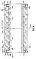
- FIG. 4 is a cross-sectional view of a track roller bearing in accordance with one embodiment of the present invention.
- FIG. 5 is a front, partial cross-sectional view of a portion of the wing illustrating side guide roller bearings in accordance with one embodiment of the present invention.
- FIG. 1 provides a plan view of a leading edge section 12 of a wing 10 of an aircraft 8.
- the wing 10 includes a plurality of slat panels 20 deployed along the leading edge 12 of the wing 10.
- an actuation system selectively extends and retracts the slat panels 20 relative to the leading edge 12 in response to flight control signals, as is generally known in the art.
- FIG. 2 is a partial cross-sectional view of the wing 10 taken along line 2-2 of FIG. 1 and illustrates one of the leading edge slats 20 in a retracted position 20' and in an extended position 20". As shown in FIG.
- the slat 20' in the retracted position (e.g., flight position) the slat 20' is located against the leading edge 12 of the wing 10 and in the deployed position (e.g., take-off and landing position) the slat 20" is deployed downwardly and forwardly away from the leading edge portion 12 of the wing 10 thus increasing a surface area of the wing 10 to vary the wing's lift-enhancing characteristics.
- An actuation system 40 of each slat 20 includes a track 50 extending along an arcuate axis A from a rear portion 52 to a forward portion 54.
- the track 50 may have multiple configurations such as, for example, an I-beam shape and a PI-beam shape.
- webbing that constitutes support elements of the track is not overly robust.
- multiple load conditions are experienced at the track during operation that may be carried and distributed by roller style bearings, as are described herein, to, for example, the wing structure of the aircraft.
- the forward portion 54 of the track 50 is pivotally coupled to an interior surface of the slat 20.
- the track 50 is coupled to the slat 20 by means of, for example, linkage bearings 60.
- the actuation system 40 also includes an actuator lever 70.
- the actuator lever 70 is coupled to the track 50 via an actuator arm 80.
- the actuator lever 70 is also coupled to a shaft 90.
- the shaft 90 extends along the leading edge section 12 of the wing 10 and operates a plurality of actuator levers (similar to lever 70) coupled to respective ones of the plurality of slat panels 20 in response to flight control commands to extend the slats when rotating in a first direction and to retract the slats 20 when rotating in a second direction.
- a plurality of actuator levers similar to lever 70
- a plurality of track roller bearings 100 are disposed about a first outer surface 56 and a second outer surface 58 of the track 50.
- the track roller bearings 100 are in rotational contact with the outer surfaces 56 and 58 of the track 50 to guide the track 50 in its arcuate path along axis A during deployment and retraction.
- the path of travel of the slat 20 is illustrated in FIG. 2 by arrow B.
- the plurality of track roller bearings 100 includes a first pair of track roller bearings 102 and 104 and a second pair of track roller bearings 106 and 108. It should be appreciated that it is within the scope of the present invention to include more or less than the illustrated two pairs of roller bearings.
- three roller bearings may be disposed about one or both of the first outer surface 56 and/or second outer surface 58 of the track 50.
- the plurality of track roller bearings 100 may include rolling element needle style track rollers or self lubricating style track rollers.
- a mounting web 110 encloses at least a portion of the track 50. In one embodiment, the mounting web 110 extends into a fuel tank disposed within the wing of the aircraft.
- the actuation system 40 includes a pinion gear 120 having teeth 122 that drive a gear track 130 disposed within an interior portion 53 of the track 50.
- the gear track 130 is positioned on a vertical centerline 55 of the track 50.
- the pinion gear 120 is coupled to a shaft 124 (such as the shaft 90) that rotates in response to flight control commands. As the shaft 124 and the pinion gear 120 rotate, a drive force is provided to the gear track 130 for driving the track 50 along axis A between one of the retracted position 20' and the extended position 20" ( FIG. 2 ).
- the track roller bearing 100 is coupled to the mounting web 110 about the track 50.
- the track roller bearing 100 is coupled to the mounting web 110 above the track 50.
- the plurality of track roller bearings 100 are coupled to the mounting web 110 about the first and second outer surfaces 56 and 58 of the track 50 to support and guide the track 50 during deployment and retraction.
- the track roller 100 is coupled to the mounting web 110 using opposing bushings 140, a mounting pin 150 and a nut 160.
- the opposing bushings 140 are comprised of eccentric bushings and the nut 160 is comprised of a castellated nut to allow adjustment to the track 50 at fit-up.
- the track roller bearing 100 includes a plurality of needle roller elements 103 (e.g., two rows of needle rollers in a double channel design).
- the needle roller elements 103 are lubricated with grease such as, for example, Aeroshell 33, Mobil 28, Aerospec 200 or Aeroplex 444 as is required by predetermined maintenance procedures.
- an outer ring 105, an inner ring and 107 and needle rollers 103 of the track roller bearings 100 are comprised of hardened stainless steel such as, for example, 440C, 52100, 422 stainless with a special nitriding process (AeroCres®)(AEROCRES is registered trademark of RBC Aircraft Products, Inc., Oxford, Connecticut USA), XD-15NW, and Cronidur 30.
- the track roller bearing 100 is comprised of a lined track roller assembly 200 including an outer ring 210 and an inner ring 220.
- the inner ring 220 is a split ring including a first portion 230 and a second portion 240.
- the first portion 230 and the second portion 240 include respective body portions 232 and 242 as well as head portions 234 and 244.
- the head portions 234 and 244 include flanges 236 and 246, respectively.
- the split ring configuration of the first portion 230 and the second portion 240 due to their ability to deflect relative to one another, accommodate potential deflection and/or bending of the mounting pin 150 from stresses that may be encountered during, for example, aircraft takeoff and landing.
- the flanges 236 and 246 control axial motion of the outer ring 210 to substantially eliminate contact of the outer ring 210 and the opposing bushings 140 utilized to mount the track roller 100 and 200 within the mounting web 110.
- the lined track roller assembly 200 may also include liners 250 disposed between bearing surfaces 212, 214 of the outer ring 210 and bearing surfaces 222, 224, 226 and 228 of the inner ring 220.
- the liners 250 are constructed of polytetrafluoroethylene (commercially available under the designation TEFLON®)(TEFLON is a registered trademark of E.I. DuPont De Nemours and Company, Wilmington, Delaware USA), polyester, graphite, fabric impregnated with a polymer, urethane, polyimide, epoxy, phenolic or other type of resin.
- the liners 250 are molded and are comprised of polytetrafluoroethylene (TEFLON®), polyester, graphite, fibers in a thermosetting composite resin made from polyester, urethane, polyimide, epoxy, phenolic or other type of resin.
- the outer ring 210 and the inner ring 220 is comprised of hardened stainless steel such as, for example, 440C, 52100, Custom 455®, Custom 465® (CUSTOM 455 and CUSTOM 465 are registered trademarks of CRS Holdings, Inc., Wilmington, Delaware, USA), and corrosion resistance steel such as 17-4PH, 15-5PH and PH13-8Mo.
- the lined track roller assembly 200 also includes shields 260 and 270 disposed about shoulder portions 216 and 218 of an outer diameter of the outer ring 210 and extending to an outer diameter 223 of the inner ring 220.
- the inventors have discovered that the shields 260 and 270 reduce friction and discourage dust and other contaminates from entering and compromising contact between the bearing surfaces 212, 214 of the outer ring 210 and bearing surfaces 222, 224, 226 and 228 of the inner ring 220.
- a plurality of side guide roller bearings 300 are disposed about opposing sides of the track 50.
- the side guide roller bearings 300 are in rotational contact with the opposing side surfaces of the track 50 to guide the track 50, along with track roller bearings 100 and 200, in its arcuate path along axis A during deployment and retraction.
- the plurality of side guide roller bearings 300 are in rotational contact with wear pads affixed to the track 50.
- the plurality of side guide roller bearings 300 include needle roller bearings having outer races, inner races and needle rollers constructed of hardened stainless steel such as, for example, 440C, 52100, 422 stainless with a special nitriding process (e.g., the aforementioned AeroCres® process), XD-15NW, and Cronidur 30.
- the side guide roller bearings 300 include end washers and seals. The end washers are constructed of, for example, 52100 steel with cadmium plate or 420 stainless steel.
- the seals are made from a thermoplastic such as, for example, an acetal copolymer with lubricant fillers or Delrin®/Celcon® (DELRIN is a registered trademark of E.I. DuPont De Nemours and Company, Wilmington, Delaware USA, and CELRON is a registered trademark of CNA Holdings, Inc., Summit, New Jersey USA).
- the seals retain grease and prevent of ingress dirt, dust and other contaminates into the bearings 300.
- needle roller elements of the bearings 300 are lubricated with grease such as, for example, Aeroshell 33, Mobil 28, Aerospec 200 or Aeroplex 444 as is required by predetermined maintenance procedures.
- both the rolling element track bearings 100 and self lubricating track roller bearings 200 include a hard outer ring or race to work in harmony with the mating track 50 that the bearings roll against.
- the track 50 is comprised of titanium or steel.
- the track 50 may be coated with a material such as, for example, tungsten carbide, although a coating is not a requirement of the present invention.
- lined track bearings are manufactured from relatively soft materials.
- inner rings are typically comprised of precipitation-hardening martensitic stainless steel such as, for example, 17-4PH steel, having a Rockwell hardness in a range of about HRc 30s to about HRc 40s
- outer rings are typically comprised of precipitation-hardening stainless steel such as, for example, custom 455 steel, having a Rockwell hardness in the range of about HRc 40s.
- Outer rings may also be manufactured as through hardened high strength steel having a Rockwell hardness of in the range of about HRc 50s to avoid flats that can occur.
- each of the outer rings is comprised of AISI Type 422 stainless steel with a special nitriding hardening process (e.g., the aforementioned AeroCres® process).
- Outer rings comprised of AISI Type 422 stainless steel with AeroCres® hardening are preferred for superior corrosion resistance and performance as compared to conventional outer rings manufactured of 440C steel.
Landscapes
- Engineering & Computer Science (AREA)
- General Engineering & Computer Science (AREA)
- Mechanical Engineering (AREA)
- Aviation & Aerospace Engineering (AREA)
- Rolling Contact Bearings (AREA)
- Transmission Devices (AREA)
- Bearings For Parts Moving Linearly (AREA)
- Sliding-Contact Bearings (AREA)
- Support Of The Bearing (AREA)
Description
- This invention relates to roller bearing assemblies for use in critical applications and, more particularly, to improved roller bearing assemblies used within an actuation system of an aircraft assembly.
- It is well known to use bearings to reduce friction between moving parts of a mechanical assembly. Similarly, it is well known to use bearings that roll on a fixed track to extend a first component from a second component. One implementation of such a track style bearing is within a wing of an aircraft. For example, fixed wing aircraft typically include slats movably arranged along a leading edge of each wing and flaps movably arranged along a trailing edge of each wing. By selectively extending, retracting and deflecting the slats and flaps aerodynamic flow conditions on a wing are influenced so as to increase lift generated by the wing during takeoff or decrease lift during landing. For example, during take-off the leading edge slats are moved forward to extend an effective chord length of the wing and improve lift. During flight, the leading edge slats and trailing edge flaps are placed in a retracted position to optimize aerodynamic conditions.
-
GB 2213113 A -
US 4471928 describes an actuation and extension mechanism for aerodynamically high-lift devices such as a wing leading edge slat or a wing trailing edge flap; wherein an aerodynamic panel is connected to one end of an extendible track member that is supported and guided by its other end through rollers fixedly mounted to wing rib structure. The document describes that the forward end of tracks is pivotally connected to slat panels. -
US 2007/0102587 A1 describes a wing leading edge slat system. The document describes that the forward end of a curved track is pivotally coupled to a slat panel. -
GB 2048181 A -
US 4399970 describes a wing leading edge slat actuation and positioning system. The actuation and positioning system comprises a unified drive and a programming mechanism that comprises a contoured camtrack somewhat in the shape of an S-camtrack and having a roller follower which is connected to a link and drive arm. -
GB 2304656 -
EP 230681 A2 -
WO 2006/114237 A1 describes a method of supporting a shaft of transmission of an electrically driven accessory drive for vehicles in a bearing housing while using an eccentric bushing. -
EP 771956 A1 - Generally speaking, leading edge slat designs employ a series of roller style bearings that guide fixed tracks to extend the leading edge slats in order to increase lift at slow speed for landing and takeoff. The tracks may have multiple configurations such as, for example, general I-beam and PI-beam shapes. Since the tracks themselves are typically not overly robust in their construction, multiple load conditions may be realized by the track roller bearings. Similarly, side load rollers or pins typically slide against the track to assist in centering the main rollers on the track. The wing also includes actuation systems for positioning the slats and flaps. Actuation systems include, for example, drive motors (e.g., hydraulic or electric drive motors), drive shafts and other bearings such as spherical bearings, bushings and linkage bearings that assist in deployment and retraction of the slats and flaps. As can be appreciated, aircraft wing designs are being continually developed as engineers seek to improve aircraft performance while increasing system capabilities. Newer designs are tending to increase the number of systems employed within a wing cross section.
- Accordingly, space within the wing cross section is at a premium. Therefore, it is desirable to improve performance characteristics of components (e.g., to reduce maintenance) within the wing while also minimizing space needed for such components.
- Based on the foregoing, it is the general object of this invention to provide an improved bearing for use in crucial applications.
- The present invention is an actuation system as defined in claim 1 for deploying and retracting a lift assisting device of a wing of an aircraft. The actuation system includes a track pivotally coupled to the lift assisting device, a shaft rotating in response to flight control signals to deploy or retract the lift assisting device, means for actuating the lift assisting device between a retracted position and a deployed position along an arcuate path, a plurality of track roller bearings and a plurality of side roller bearings. The roller bearings rotatably contact the track to guide the track along the arcuate path. In one embodiment, the track roller bearings are comprised of an outer ring, a split inner ring and liners disposed between bearing surfaces of the outer and the inner rings. The split inner ring is configured for accommodating deflection and bending of a mounting pin coupling the track roller bearing in proximity to the track. In another embodiment, the track roller bearings are comprised of an outer race, an inner race and needle roller elements.
- In one embodiment, the means for actuating includes a gear track coupled to the track and a pinion gear coupled to the shaft. The pinion gear has gear teeth that engage the gear track. When the shaft rotates in a first direction the pinion gear engages the gear track to move the lift assisting device from the retracted to the deployed position along the arcuate path. When the shaft rotates in a second direction the pinion gear engages the gear track to move the lift assisting device from the deployed position to the retracted position along the arcuate path. In another embodiment, the means for actuating includes an actuator arm coupled to the track and an actuator lever coupled to the shaft and to the actuator arm. When the shaft rotates in the first direction the actuator lever drives the actuator arm to move the track and the lift assisting device from the retracted to the deployed position along the arcuate path. When the shaft rotates in the second direction the actuator lever drives the actuator arm to move the track and the lift assisting device from the deployed position to the retracted position along the arcuate path.
- In still another embodiment, each of the plurality of track roller bearings are comprised of an outer ring having inner bearing surfaces, an inner split ring having a first portion and a second portion, each of the first and second portions having outer bearing surfaces, and a plurality of liners disposed between the inner bearing surfaces of the outer ring and the outer bearing surfaces of the inner ring. Each of the inner rings is comprised of 17-4PH steel and each of the outer rings is comprised of AISI Type 422 stainless steel. In one embodiment, each of the outer rings is comprised of AISI Type 422 stainless steel with a special nitriding hardening process.
-
FIG. 1 is a plan view of a wing of an aircraft illustrating a plurality of slat panels located at a leading edge of the wing; -
FIG. 2 is a side cross-sectional view of the wing ofFIG. 1 taken along line 2-2 illustrating one of the slat panels in a deployed and a retracted position; -
FIG. 3 is a front, partial cross-sectional view of a portion of the wing illustrating an actuation system for a slat panel, in accordance with one embodiment of the present invention; -
FIG. 4 is a cross-sectional view of a track roller bearing in accordance with one embodiment of the present invention; -
FIG. 5 is a front, partial cross-sectional view of a portion of the wing illustrating side guide roller bearings in accordance with one embodiment of the present invention. -
FIG. 1 provides a plan view of aleading edge section 12 of awing 10 of anaircraft 8. Thewing 10 includes a plurality ofslat panels 20 deployed along the leadingedge 12 of thewing 10. As described herein, an actuation system selectively extends and retracts theslat panels 20 relative to the leadingedge 12 in response to flight control signals, as is generally known in the art.FIG. 2 is a partial cross-sectional view of thewing 10 taken along line 2-2 ofFIG. 1 and illustrates one of theleading edge slats 20 in a retracted position 20' and in anextended position 20". As shown inFIG. 2 , in the retracted position (e.g., flight position) the slat 20' is located against the leadingedge 12 of thewing 10 and in the deployed position (e.g., take-off and landing position) theslat 20" is deployed downwardly and forwardly away from theleading edge portion 12 of thewing 10 thus increasing a surface area of thewing 10 to vary the wing's lift-enhancing characteristics. - An actuation system 40 of each
slat 20 includes atrack 50 extending along an arcuate axis A from arear portion 52 to aforward portion 54. It should be appreciated that thetrack 50 may have multiple configurations such as, for example, an I-beam shape and a PI-beam shape. Generally speaking, webbing that constitutes support elements of the track is not overly robust. As such, multiple load conditions are experienced at the track during operation that may be carried and distributed by roller style bearings, as are described herein, to, for example, the wing structure of the aircraft. - As shown in
FIG. 2 , theforward portion 54 of thetrack 50 is pivotally coupled to an interior surface of theslat 20. In one embodiment, thetrack 50 is coupled to theslat 20 by means of, for example,linkage bearings 60. The actuation system 40 also includes anactuator lever 70. Theactuator lever 70 is coupled to thetrack 50 via anactuator arm 80. Theactuator lever 70 is also coupled to ashaft 90. As is generally known in the art, theshaft 90 extends along theleading edge section 12 of thewing 10 and operates a plurality of actuator levers (similar to lever 70) coupled to respective ones of the plurality ofslat panels 20 in response to flight control commands to extend the slats when rotating in a first direction and to retract theslats 20 when rotating in a second direction. - A plurality of
track roller bearings 100 are disposed about a firstouter surface 56 and a secondouter surface 58 of thetrack 50. Thetrack roller bearings 100 are in rotational contact with theouter surfaces track 50 to guide thetrack 50 in its arcuate path along axis A during deployment and retraction. The path of travel of theslat 20 is illustrated inFIG. 2 by arrow B. As shown inFIG. 2 , the plurality oftrack roller bearings 100 includes a first pair oftrack roller bearings track roller bearings outer surface 56 and/or secondouter surface 58 of thetrack 50. As described in detail below, it is also within the scope of the present invention for the plurality oftrack roller bearings 100 to include rolling element needle style track rollers or self lubricating style track rollers. In one embodiment, a mountingweb 110 encloses at least a portion of thetrack 50. In one embodiment, the mountingweb 110 extends into a fuel tank disposed within the wing of the aircraft. - In one embodiment illustrated in
FIG. 3 , the actuation system 40 includes apinion gear 120 havingteeth 122 that drive agear track 130 disposed within aninterior portion 53 of thetrack 50. Preferably, thegear track 130 is positioned on avertical centerline 55 of thetrack 50. Thepinion gear 120 is coupled to a shaft 124 (such as the shaft 90) that rotates in response to flight control commands. As theshaft 124 and thepinion gear 120 rotate, a drive force is provided to thegear track 130 for driving thetrack 50 along axis A between one of the retracted position 20' and theextended position 20" (FIG. 2 ). As shown inFIG. 3 , thetrack roller bearing 100 is coupled to the mountingweb 110 about thetrack 50. For example, as shown inFIG. 3 , thetrack roller bearing 100 is coupled to the mountingweb 110 above thetrack 50. - As shown in
FIG. 2 , the plurality oftrack roller bearings 100 are coupled to the mountingweb 110 about the first and secondouter surfaces track 50 to support and guide thetrack 50 during deployment and retraction. In one embodiment, illustrated inFIG. 3 , thetrack roller 100 is coupled to the mountingweb 110 using opposingbushings 140, a mountingpin 150 and anut 160. In one embodiment, the opposingbushings 140 are comprised of eccentric bushings and thenut 160 is comprised of a castellated nut to allow adjustment to thetrack 50 at fit-up. As shown inFIG. 3 , thetrack roller bearing 100 includes a plurality of needle roller elements 103 (e.g., two rows of needle rollers in a double channel design). Theneedle roller elements 103 are lubricated with grease such as, for example, Aeroshell 33, Mobil 28,Aerospec 200 or Aeroplex 444 as is required by predetermined maintenance procedures. In one embodiment, anouter ring 105, an inner ring and 107 andneedle rollers 103 of thetrack roller bearings 100 are comprised of hardened stainless steel such as, for example, 440C, 52100, 422 stainless with a special nitriding process (AeroCres®)(AEROCRES is registered trademark of RBC Aircraft Products, Inc., Oxford, Connecticut USA), XD-15NW, and Cronidur 30. - In another embodiment, illustrated in
FIG. 4 , thetrack roller bearing 100 is comprised of a linedtrack roller assembly 200 including anouter ring 210 and aninner ring 220. Theinner ring 220 is a split ring including afirst portion 230 and asecond portion 240. In one embodiment, thefirst portion 230 and thesecond portion 240 includerespective body portions head portions head portions flanges first portion 230 and thesecond portion 240 due to their ability to deflect relative to one another, accommodate potential deflection and/or bending of the mountingpin 150 from stresses that may be encountered during, for example, aircraft takeoff and landing. As can be appreciated, unless accounted for a bending of the mountingpin 150 may result in high friction or binding of thetrack roller flanges outer ring 210 to substantially eliminate contact of theouter ring 210 and the opposingbushings 140 utilized to mount thetrack roller web 110. - As shown in
FIG. 4 , the linedtrack roller assembly 200 may also includeliners 250 disposed between bearingsurfaces outer ring 210 and bearingsurfaces inner ring 220. In one embodiment, theliners 250 are constructed of polytetrafluoroethylene (commercially available under the designation TEFLON®)(TEFLON is a registered trademark of E.I. DuPont De Nemours and Company, Wilmington, Delaware USA), polyester, graphite, fabric impregnated with a polymer, urethane, polyimide, epoxy, phenolic or other type of resin. In one embodiment, theliners 250 are molded and are comprised of polytetrafluoroethylene (TEFLON®), polyester, graphite, fibers in a thermosetting composite resin made from polyester, urethane, polyimide, epoxy, phenolic or other type of resin. In one embodiment, theouter ring 210 and theinner ring 220 is comprised of hardened stainless steel such as, for example, 440C, 52100, Custom 455®, Custom 465® (CUSTOM 455 and CUSTOM 465 are registered trademarks of CRS Holdings, Inc., Wilmington, Delaware, USA), and corrosion resistance steel such as 17-4PH, 15-5PH and PH13-8Mo. - In one embodiment, the lined
track roller assembly 200 also includesshields shoulder portions outer ring 210 and extending to anouter diameter 223 of theinner ring 220. The inventors have discovered that theshields surfaces outer ring 210 and bearingsurfaces inner ring 220. - In one embodiment, illustrated in
FIG. 5 , a plurality of side guideroller bearings 300 are disposed about opposing sides of thetrack 50. The side guideroller bearings 300 are in rotational contact with the opposing side surfaces of thetrack 50 to guide thetrack 50, along withtrack roller bearings roller bearings 300 are in rotational contact with wear pads affixed to thetrack 50. In one embodiment, the plurality of side guideroller bearings 300 include needle roller bearings having outer races, inner races and needle rollers constructed of hardened stainless steel such as, for example, 440C, 52100, 422 stainless with a special nitriding process (e.g., the aforementioned AeroCres® process), XD-15NW, and Cronidur 30. In yet another embodiment, the sideguide roller bearings 300 include end washers and seals. The end washers are constructed of, for example, 52100 steel with cadmium plate or 420 stainless steel. The seals are made from a thermoplastic such as, for example, an acetal copolymer with lubricant fillers or Delrin®/Celcon® (DELRIN is a registered trademark of E.I. DuPont De Nemours and Company, Wilmington, Delaware USA, and CELRON is a registered trademark of CNA Holdings, Inc., Summit, New Jersey USA). The seals retain grease and prevent of ingress dirt, dust and other contaminates into thebearings 300. In one embodiment, needle roller elements of thebearings 300 are lubricated with grease such as, for example, Aeroshell 33, Mobil 28,Aerospec 200 or Aeroplex 444 as is required by predetermined maintenance procedures. - As described above, both the rolling
element track bearings 100 and self lubricatingtrack roller bearings 200 include a hard outer ring or race to work in harmony with themating track 50 that the bearings roll against. In one embodiment, thetrack 50 is comprised of titanium or steel. In one embodiment, thetrack 50 may be coated with a material such as, for example, tungsten carbide, although a coating is not a requirement of the present invention. - In addition to a unique bearing mounting configuration, another aspect of the present invention is related to the materials from which the bearings are manufactured. Historically, lined track bearings are manufactured from relatively soft materials. For example, inner rings are typically comprised of precipitation-hardening martensitic stainless steel such as, for example, 17-4PH steel, having a Rockwell hardness in a range of about HRc 30s to about HRc 40s, while outer rings are typically comprised of precipitation-hardening stainless steel such as, for example, custom 455 steel, having a Rockwell hardness in the range of about HRc 40s. Outer rings may also be manufactured as through hardened high strength steel having a Rockwell hardness of in the range of about HRc 50s to avoid flats that can occur. 440C steel has also been used for outer rings. The inventors have discovered that, in certain applications, it is beneficial to maintain inner rings manufactured from 17-4PH steel, and that it is desirable to manufacture outer rings of AISI Type 422 stainless steel. In one embodiment, each of the outer rings is comprised of AISI Type 422 stainless steel with a special nitriding hardening process (e.g., the aforementioned AeroCres® process). Outer rings comprised of AISI Type 422 stainless steel with AeroCres® hardening are preferred for superior corrosion resistance and performance as compared to conventional outer rings manufactured of 440C steel.
- Although the invention has been described with reference to particular embodiments thereof, it will be understood by one of ordinary skill in the art, upon a reading and understanding of the foregoing disclosure, that numerous variations and alterations to the disclosed embodiments will fall within the scope of this invention and of the appended claims.
Claims (14)
- An actuation system for deploying and retracting a lift assisting device (20) of a wing (10) of an aircraft (8), in combination with said lift assisting device (20), the actuation system comprising:a track (50) coupled to the lift assisting device (20), the track (50) having first (56) and second (58) outer surfaces and side surfaces;a shaft (90) for being rotationally coupled within the wing (10) of the aircraft (8) and operable, in response to flight control signals, to deploy or retract the lift assisting device;means (70, 80, 120, 130) for actuating the lift assisting device (20), coupled to the shaft (90), between a retracted position (20') to a deployed position (20") along an arcuate path (A);a plurality of track roller bearings (100; 102, 104, 106, 108) rotatably contacting the first (56) and second (58) outer surfaces of the track (50) to guide the track (50) along the arcuate path (A); anda plurality of side roller bearings (300) rotatably contacting at least one side of the track (50) to guide the track (50) along the arcuate path (A), characterized in that the track (50) is pivotally coupled to the lift assisting device (20) and in that the plurality of track roller bearings (100) includes at least one lined track roller assembly (200) and wherein the lined track roller assembly (200) comprises:further comprising:an outer ring (210) having inner bearing surfaces (212, 214); andan inner ring (220), anda plurality of liners (250) disposed between the inner bearing surfaces (212, 214) of the outer ring (210) and outer bearing surfaces (222, 224, 226, 228) of the inner ring (220).
- The actuation system of claim 1, wherein the means for actuating is comprised of:a gear track (130) coupled to the track (50); anda pinion gear (120) coupled to the shaft (90), the pinion gear (120) having gear teeth (122) that engage the gear track (130);wherein when the shaft (90) rotates in a first direction the pinion gear (120) engages the gear track (130) to move the lift assisting device (20) from the retracted (20') to the deployed (20") position along the arcuate path (A), and when the shaft (90) rotates in a second direction the pinion gear (120) engages the gear track (130) to move the lift assisting device (20) from the deployed position (20") to the retracted position (20') along the arcuate path (A).
- The actuation system of claim 1, wherein the means for actuating is comprised of:an actuator arm (80) coupled to the track (50); andan actuator lever (70) coupled to the shaft (90) and to the actuator arm (80);wherein when the shaft (90) rotates in a first direction the actuator lever (70) drives the actuator arm (80) to move the track (50) and the lift assisting device (20) from the retracted (20') to the deployed (20") position along the arcuate path (A), and when the shaft (90) rotates in a second direction the actuator lever (70) drives the actuator arm (80) to move the track (50) and the lift assisting device (20) from the deployed position (20") to the retracted position (20') along the arcuate path (A).
- The actuation system of claim 1, wherein the plurality of track roller bearings includes at least one track roller bearing (102, 104) in rotational contact with an upper surface (56) of the track (50) and at least one track roller bearing (106, 108) in rotational contact with a lower surface (58) of the track (50).
- The actuation system of claim 1, wherein the actuation system further includes a mounting web (110) enclosing at least a portion of the track (50) and wherein the plurality of track roller bearings (102, 104, 106, 108) are coupled to the mounting web (110).
- The actuation system of claim 5, wherein the track roller bearings (100) are coupled to the mounting web (110) with opposing bushings (140), a mounting pin (150) and a nut (160).
- The actuation system of claim 6, wherein the opposing bushings (140) are comprised of eccentric bushings and the nut (160) is comprised of a castellated nut to allow adjustment to the track (50) at fit-up.
- The actuation system of claim 1, wherein the plurality of track roller bearings (100) includes at least one track roller bearing (100) having needle roller elements (103).
- The actuation system of claim 1, wherein the liners (250) are comprised of at least one of polytetrafluoroethylene, polyester, graphite, fabric impregnated with a polymer, urethane, polyimide, epoxy, and phenolic.
- The actuation system of claim 1, wherein the liners are molded and comprised of at least one of polytetrafluoroethylene, polyester, graphite, fibers in a thermosetting composite resin made from polyester, urethane, polyimide, epoxy, and phenolic.
- The actuation system of claim 1, further comprising:a plurality of shields (260, 270) disposed about shoulder portions (216, 218) of an outer diameter of the outer ring (210) and extending to an outer diameter (223) of the inner ring (220).
- The actuation system of claim 1, wherein the inner ring is a
split ring (220) having a first portion (230) and a second portion (240), each of the first (230) and second (240) portions having the outer bearing surfaces (222, 224, 226, 228); and
wherein the inner rings (220) are comprised of 17-4PH steel and the outer ring (210) is comprised of AISI Type 422 stainless steel with a special nitriding hardening process. - The actuating system of claim 1, wherein the inner ring (220) is a split ring having a first portion (230) and a second portion (240), each of the first (230) and second (240) portions having outer bearing surfaces (222, 224, 226, 228);
wherein the split inner ring (220) is configured for accommodating deflection and bending of a mounting pin (150) coupling the lined track roller bearing (200) to the track (50). - The actuation system of claim 13, wherein the first portion (230) and the second portion (240) of the inner split ring (220) each include a body portion (232, 242) and a head portion (234, 244), and wherein the head portions (234, 244) each have a flange (236, 246) for limiting axial motion of the outer ring (210).
Applications Claiming Priority (1)
| Application Number | Priority Date | Filing Date | Title |
|---|---|---|---|
| US99274607P | 2007-12-06 | 2007-12-06 |
Publications (3)
| Publication Number | Publication Date |
|---|---|
| EP2067696A2 EP2067696A2 (en) | 2009-06-10 |
| EP2067696A3 EP2067696A3 (en) | 2012-04-18 |
| EP2067696B1 true EP2067696B1 (en) | 2013-08-21 |
Family
ID=40219309
Family Applications (1)
| Application Number | Title | Priority Date | Filing Date |
|---|---|---|---|
| EP08168716.2A Not-in-force EP2067696B1 (en) | 2007-12-06 | 2008-11-10 | Actuation system for a lift assisting device and roller bearings used therein |
Country Status (8)
| Country | Link |
|---|---|
| US (2) | US8025257B2 (en) |
| EP (1) | EP2067696B1 (en) |
| JP (2) | JP5162421B2 (en) |
| CN (1) | CN101450712B (en) |
| BR (1) | BRPI0806655B1 (en) |
| CA (1) | CA2643029C (en) |
| ES (1) | ES2436116T3 (en) |
| MX (1) | MX2008015243A (en) |
Cited By (4)
| Publication number | Priority date | Publication date | Assignee | Title |
|---|---|---|---|---|
| US9561845B2 (en) | 2007-12-06 | 2017-02-07 | Roller Bearing Company Of America, Inc. | Bearing installed on an aircraft structure |
| US9890814B2 (en) | 2014-06-03 | 2018-02-13 | Roller Bearing Company Of America, Inc. | Cage for hourglass roller bearings |
| US10012265B2 (en) | 2007-12-06 | 2018-07-03 | Roller Bearing Company Of America, Inc. | Corrosion resistant bearing material |
| US10077808B2 (en) | 2013-12-18 | 2018-09-18 | Roller Bearing Company Of America, Inc. | Roller profile for hourglass roller bearings in aircraft |
Families Citing this family (30)
| Publication number | Priority date | Publication date | Assignee | Title |
|---|---|---|---|---|
| US10023302B2 (en) | 2007-12-06 | 2018-07-17 | Roller Bearing Company Of America, Inc. | Actuation system for a lift assisting device and lined track rollers used therein |
| US20110220762A1 (en) * | 2007-12-06 | 2011-09-15 | Roller Bearing Company Of America, Inc. | Actuation system for a lift assisting device and roller bearings used therein |
| US8025257B2 (en) * | 2007-12-06 | 2011-09-27 | Roller Bearing Company Of America, Inc. | Actuation system for a lift assisting device and roller bearings used therein |
| US10400818B2 (en) * | 2007-12-06 | 2019-09-03 | Roller Bearing Company Of America, Inc. | Track roller bearings with rolling elements or liners |
| GB0906952D0 (en) * | 2009-04-23 | 2009-06-03 | Airbus Uk Ltd | Aircraft assembly and spar |
| US9261132B2 (en) | 2009-04-24 | 2016-02-16 | Roller Bearing Company Of America, Inc. | Low friction bearing assembly and link apparatus |
| ES2427390T3 (en) * | 2009-10-29 | 2013-10-30 | Asco Industries | Guide rail for hyper-sustaining device |
| DE102009057340A1 (en) * | 2009-12-07 | 2011-06-09 | Airbus Operations Gmbh | High lift system for an aircraft, method of moving a lift flap, and aircraft with a high lift system |
| US8876065B2 (en) * | 2011-10-21 | 2014-11-04 | Gulfstream Aerospace Corporation | Flap roller arrangement, flap assembly, and method for removing a roller assembly from a flap fitting |
| WO2014021958A1 (en) | 2012-04-30 | 2014-02-06 | Roller Bearing Company Of America, Inc. | Hybrid bearing assembly with rolling elements and plain bearing |
| GB201209686D0 (en) * | 2012-05-31 | 2012-07-18 | Airbus Operations Ltd | A slat support assembly |
| WO2014100411A1 (en) * | 2012-12-19 | 2014-06-26 | Roller Bearing Company Of America, Inc. | Actuation system for a lift assisting device and lined track rollers used therein |
| JP6178581B2 (en) * | 2013-01-29 | 2017-08-09 | 三菱航空機株式会社 | Aircraft slat, slat mounting position adjustment method, and aircraft |
| US9458825B2 (en) | 2013-03-15 | 2016-10-04 | Frontier Wind, Llc | Actuation mechanisms for load management devices on aerodynamic blades |
| US8951358B2 (en) * | 2013-03-15 | 2015-02-10 | Honeywell International Inc. | Cleaning compositions and methods |
| EP2840272A3 (en) * | 2013-07-12 | 2015-10-21 | Roller Bearing Company of America, Inc. | Electrical conductor for bearing used on actuation system for aircraft lift assisting devices |
| CN104554709B (en) * | 2013-10-21 | 2016-08-24 | 哈尔滨飞机工业集团有限责任公司 | A kind of flap kinematics stopper mechanism |
| CN104033488A (en) * | 2014-06-18 | 2014-09-10 | 洛阳轴研科技股份有限公司 | Design method of miniature ball bearing for ultra-high-speed abrasive drilling |
| JP2016191410A (en) | 2015-03-31 | 2016-11-10 | ミネベア株式会社 | Track roller bearing |
| US10677464B2 (en) * | 2015-05-15 | 2020-06-09 | Rohr, Inc. | Self-centering bolted fluid fitting |
| EP3162903A1 (en) * | 2015-10-26 | 2017-05-03 | SKF Aerospace France | Process of treatment of a ring for a bearing and a bearing |
| EP3339163A1 (en) * | 2016-12-22 | 2018-06-27 | Airbus Operations GmbH | Wing for an aircraft |
| EP3395678B1 (en) | 2017-04-26 | 2021-05-26 | Asco Industries NV | Guidance assembly for an airfoil leading edge high-lift device carrier track |
| EP3501977B1 (en) | 2017-12-19 | 2021-08-11 | Asco Industries NV | Deployment system for an airfoil high lift leading edge device |
| GB2579221A (en) * | 2018-11-26 | 2020-06-17 | Airbus Operations Ltd | Aircraft control mechanism |
| US11001377B1 (en) * | 2020-05-21 | 2021-05-11 | Horizon Aircraft Inc. | Aircraft airfoil and aircraft having the same |
| US11338907B2 (en) * | 2020-05-29 | 2022-05-24 | The Boeing Company | Actuation assemblies for flight control surfaces |
| US11897613B2 (en) | 2021-06-08 | 2024-02-13 | Airbus Operations Gmbh | Wing for an aircraft |
| EP4566940A1 (en) | 2023-12-06 | 2025-06-11 | Airbus Operations GmbH | Drive system for a lift control device of an aircraft, aircraft wing and aircraft |
| US12441455B1 (en) * | 2025-01-27 | 2025-10-14 | The Boeing Company | Wing assemblies and aircraft with gap-adjustment assemblies for slats |
Family Cites Families (24)
| Publication number | Priority date | Publication date | Assignee | Title |
|---|---|---|---|---|
| US2620147A (en) * | 1950-05-31 | 1952-12-02 | Boeing Co | Airplane flap control mechanism |
| US2938680A (en) * | 1957-07-02 | 1960-05-31 | North American Aviation Inc | Multiple position airfoil slat |
| DE2916040C2 (en) * | 1979-04-20 | 1986-01-02 | Messerschmitt-Bölkow-Blohm GmbH, 8012 Ottobrunn | Wing for an aircraft with movable slats |
| US4471928A (en) * | 1980-08-13 | 1984-09-18 | The Boeing Company | Extendible airfoil track assembly |
| US4399970A (en) * | 1980-11-13 | 1983-08-23 | The Boeing Company | Wing leading edge slat |
| GB2097486B (en) * | 1981-04-20 | 1985-07-10 | Kamatics Corp | Bearings |
| JPS62113697A (en) * | 1985-11-14 | 1987-05-25 | 財団法人 日本航空機開発協会 | Link type operation mechanism of aircraft wing rear-edge flap |
| US4753402A (en) * | 1985-12-30 | 1988-06-28 | The Boeing Company | Biased leading edge slat apparatus |
| GB8711252D0 (en) * | 1987-05-13 | 1987-07-15 | British Aerospace | High lift device |
| GB2213113B (en) * | 1987-12-03 | 1991-06-26 | British Aerospace | Support arrangement for extendible high lift devices |
| JPH0623768Y2 (en) * | 1989-08-04 | 1994-06-22 | 日本精工株式会社 | Linear motion guide bearing device |
| US5544847A (en) * | 1993-11-10 | 1996-08-13 | The Boeing Company | Leading edge slat/wing combination |
| GB2304656B (en) * | 1995-08-26 | 1999-10-13 | British Aerospace | Deployment mechanisms for aircraft auxiliary aerofoils |
| DE19541247A1 (en) * | 1995-11-06 | 1997-05-07 | Klein Schanzlin & Becker Ag | Plain bearing for a machine shaft |
| CN1204602A (en) * | 1997-07-08 | 1999-01-13 | 马金山 | Airplane high-efficient control panel |
| US6180574B1 (en) * | 1998-12-16 | 2001-01-30 | Rexnord Corporation | Self-lubricating bearing and coating |
| US6139261A (en) * | 1999-04-16 | 2000-10-31 | General Electric Company | Bushing assembly with removable wear sleeve |
| US7081062B2 (en) * | 2002-11-25 | 2006-07-25 | Delbert Tesar | Standardized rotary actuator |
| CN2741869Y (en) * | 2004-08-25 | 2005-11-23 | 栾松瑞 | Improved plane turning and lifting device |
| JP2006300130A (en) * | 2005-04-18 | 2006-11-02 | Ntn Corp | Bearing structure |
| DE102005019501A1 (en) * | 2005-04-27 | 2006-11-09 | Valeo Wischersysteme Gmbh | Method for supporting a shaft and bearing arrangement |
| US7249735B2 (en) * | 2005-06-30 | 2007-07-31 | The Boeing Company | Translating conduit apparatus for an airplane or equipment |
| US20070102587A1 (en) * | 2005-11-07 | 2007-05-10 | The Boeing Company | Wing leading edge slat system |
| US8025257B2 (en) * | 2007-12-06 | 2011-09-27 | Roller Bearing Company Of America, Inc. | Actuation system for a lift assisting device and roller bearings used therein |
-
2008
- 2008-08-29 US US12/201,062 patent/US8025257B2/en active Active
- 2008-11-05 CA CA2643029A patent/CA2643029C/en active Active
- 2008-11-10 ES ES08168716T patent/ES2436116T3/en active Active
- 2008-11-10 EP EP08168716.2A patent/EP2067696B1/en not_active Not-in-force
- 2008-11-27 JP JP2008302409A patent/JP5162421B2/en not_active Expired - Fee Related
- 2008-11-28 MX MX2008015243A patent/MX2008015243A/en active IP Right Grant
- 2008-12-04 CN CN2008101817137A patent/CN101450712B/en not_active Expired - Fee Related
- 2008-12-05 BR BRPI0806655-8A patent/BRPI0806655B1/en not_active IP Right Cessation
-
2011
- 2011-05-24 US US13/114,099 patent/US8387924B2/en not_active Expired - Fee Related
-
2012
- 2012-12-18 JP JP2012276286A patent/JP2013052873A/en active Pending
Cited By (4)
| Publication number | Priority date | Publication date | Assignee | Title |
|---|---|---|---|---|
| US9561845B2 (en) | 2007-12-06 | 2017-02-07 | Roller Bearing Company Of America, Inc. | Bearing installed on an aircraft structure |
| US10012265B2 (en) | 2007-12-06 | 2018-07-03 | Roller Bearing Company Of America, Inc. | Corrosion resistant bearing material |
| US10077808B2 (en) | 2013-12-18 | 2018-09-18 | Roller Bearing Company Of America, Inc. | Roller profile for hourglass roller bearings in aircraft |
| US9890814B2 (en) | 2014-06-03 | 2018-02-13 | Roller Bearing Company Of America, Inc. | Cage for hourglass roller bearings |
Also Published As
| Publication number | Publication date |
|---|---|
| JP5162421B2 (en) | 2013-03-13 |
| US20110220760A1 (en) | 2011-09-15 |
| BRPI0806655A2 (en) | 2010-04-06 |
| CN101450712B (en) | 2012-06-06 |
| MX2008015243A (en) | 2009-06-17 |
| CN101450712A (en) | 2009-06-10 |
| JP2009137574A (en) | 2009-06-25 |
| EP2067696A2 (en) | 2009-06-10 |
| JP2013052873A (en) | 2013-03-21 |
| US8387924B2 (en) | 2013-03-05 |
| BRPI0806655B1 (en) | 2020-11-17 |
| US20090146014A1 (en) | 2009-06-11 |
| CA2643029A1 (en) | 2009-06-06 |
| US8025257B2 (en) | 2011-09-27 |
| EP2067696A3 (en) | 2012-04-18 |
| ES2436116T3 (en) | 2013-12-27 |
| CA2643029C (en) | 2013-01-15 |
Similar Documents
| Publication | Publication Date | Title |
|---|---|---|
| US8387924B2 (en) | Actuation system for a lift assisting device and roller bearings used therein | |
| US10023302B2 (en) | Actuation system for a lift assisting device and lined track rollers used therein | |
| US10400818B2 (en) | Track roller bearings with rolling elements or liners | |
| US20110220762A1 (en) | Actuation system for a lift assisting device and roller bearings used therein | |
| EP3527488B1 (en) | Single piece inner and outer race roller bearing with rolling elements | |
| US20140131512A1 (en) | Seal and electrical conductor for lined track rollers used on actuation system for aircraft lift assisting devices | |
| US20210277950A1 (en) | Hybrid bearing assembly with rolling elements and plain bearing | |
| US20140339358A1 (en) | Electrical conductor for lined track rollers used on actuation system for aircraft lift assisting devices | |
| US6280141B1 (en) | Swash-plates system for control of the pitch of rotor blades with rotating plate driver | |
| US9278756B2 (en) | Dry lubricated linear actuator for in blade rotor control | |
| JP2013052873A5 (en) | ||
| US9517839B2 (en) | Electromechanical linear actuator for in blade rotor control | |
| EP2840272A2 (en) | Electrical conductor for bearing used on actuation system for aircraft lift assisting devices | |
| DE112012001182T5 (en) | Wind Turbine Generator | |
| CA2114724C (en) | Compensation for kinematic foreshortening effect in pitch control system for rotary wing aircraft | |
| EP2934999B1 (en) | Actuation system for a lift assisting device and lined track rollers used therein | |
| KR102126372B1 (en) | Variable collective pitch rotor and aircraft |
Legal Events
| Date | Code | Title | Description |
|---|---|---|---|
| PUAI | Public reference made under article 153(3) epc to a published international application that has entered the european phase |
Free format text: ORIGINAL CODE: 0009012 |
|
| AK | Designated contracting states |
Kind code of ref document: A2 Designated state(s): AT BE BG CH CY CZ DE DK EE ES FI FR GB GR HR HU IE IS IT LI LT LU LV MC MT NL NO PL PT RO SE SI SK TR |
|
| AX | Request for extension of the european patent |
Extension state: AL BA MK RS |
|
| RIC1 | Information provided on ipc code assigned before grant |
Ipc: F16C 23/04 20060101ALI20111012BHEP Ipc: F16C 23/10 20060101ALI20111012BHEP Ipc: F16C 19/48 20060101ALI20111012BHEP Ipc: F16C 11/02 20060101ALI20111012BHEP Ipc: B64C 9/22 20060101AFI20111012BHEP Ipc: F16C 17/10 20060101ALI20111012BHEP |
|
| PUAL | Search report despatched |
Free format text: ORIGINAL CODE: 0009013 |
|
| AK | Designated contracting states |
Kind code of ref document: A3 Designated state(s): AT BE BG CH CY CZ DE DK EE ES FI FR GB GR HR HU IE IS IT LI LT LU LV MC MT NL NO PL PT RO SE SI SK TR |
|
| AX | Request for extension of the european patent |
Extension state: AL BA MK RS |
|
| RIC1 | Information provided on ipc code assigned before grant |
Ipc: F16C 29/04 20060101ALI20120315BHEP Ipc: F16C 23/04 20060101ALI20120315BHEP Ipc: F16C 23/10 20060101ALI20120315BHEP Ipc: F16C 19/48 20060101ALI20120315BHEP Ipc: F16C 17/10 20060101ALI20120315BHEP Ipc: B64C 9/22 20060101AFI20120315BHEP Ipc: F16C 11/02 20060101ALI20120315BHEP |
|
| 17P | Request for examination filed |
Effective date: 20121012 |
|
| 17Q | First examination report despatched |
Effective date: 20121127 |
|
| AKX | Designation fees paid |
Designated state(s): AT BE BG CH CY LI |
|
| REG | Reference to a national code |
Ref country code: DE Ref legal event code: R108 |
|
| RBV | Designated contracting states (corrected) |
Designated state(s): AT BE BG CH CY CZ LI |
|
| RBV | Designated contracting states (corrected) |
Designated state(s): AT BE BG CH CY CZ DE DK EE ES FI FR GB GR HR HU IE IS IT LI LT LU LV MC MT NL NO PL PT RO SE SI SK TR |
|
| GRAP | Despatch of communication of intention to grant a patent |
Free format text: ORIGINAL CODE: EPIDOSNIGR1 |
|
| INTG | Intention to grant announced |
Effective date: 20130503 |
|
| GRAS | Grant fee paid |
Free format text: ORIGINAL CODE: EPIDOSNIGR3 |
|
| GRAA | (expected) grant |
Free format text: ORIGINAL CODE: 0009210 |
|
| AK | Designated contracting states |
Kind code of ref document: B1 Designated state(s): AT BE BG CH CY CZ DE DK EE ES FI FR GB GR HR HU IE IS IT LI LT LU LV MC MT NL NO PL PT RO SE SI SK TR |
|
| REG | Reference to a national code |
Ref country code: GB Ref legal event code: FG4D |
|
| REG | Reference to a national code |
Ref country code: CH Ref legal event code: EP |
|
| REG | Reference to a national code |
Ref country code: AT Ref legal event code: REF Ref document number: 627893 Country of ref document: AT Kind code of ref document: T Effective date: 20130915 |
|
| REG | Reference to a national code |
Ref country code: IE Ref legal event code: FG4D |
|
| REG | Reference to a national code |
Ref country code: DE Ref legal event code: R096 Ref document number: 602008026916 Country of ref document: DE Effective date: 20131017 |
|
| REG | Reference to a national code |
Ref country code: SE Ref legal event code: TRGR |
|
| REG | Reference to a national code |
Ref country code: CH Ref legal event code: NV Representative=s name: ING. MARCO ZARDI C/O M. ZARDI AND CO. S.A., CH |
|
| REG | Reference to a national code |
Ref country code: ES Ref legal event code: FG2A Ref document number: 2436116 Country of ref document: ES Kind code of ref document: T3 Effective date: 20131227 |
|
| REG | Reference to a national code |
Ref country code: NL Ref legal event code: VDEP Effective date: 20130821 Ref country code: AT Ref legal event code: MK05 Ref document number: 627893 Country of ref document: AT Kind code of ref document: T Effective date: 20130821 |
|
| REG | Reference to a national code |
Ref country code: LT Ref legal event code: MG4D |
|
| PG25 | Lapsed in a contracting state [announced via postgrant information from national office to epo] |
Ref country code: AT Free format text: LAPSE BECAUSE OF FAILURE TO SUBMIT A TRANSLATION OF THE DESCRIPTION OR TO PAY THE FEE WITHIN THE PRESCRIBED TIME-LIMIT Effective date: 20130821 Ref country code: IS Free format text: LAPSE BECAUSE OF FAILURE TO SUBMIT A TRANSLATION OF THE DESCRIPTION OR TO PAY THE FEE WITHIN THE PRESCRIBED TIME-LIMIT Effective date: 20131221 Ref country code: HR Free format text: LAPSE BECAUSE OF FAILURE TO SUBMIT A TRANSLATION OF THE DESCRIPTION OR TO PAY THE FEE WITHIN THE PRESCRIBED TIME-LIMIT Effective date: 20130821 Ref country code: CY Free format text: LAPSE BECAUSE OF FAILURE TO SUBMIT A TRANSLATION OF THE DESCRIPTION OR TO PAY THE FEE WITHIN THE PRESCRIBED TIME-LIMIT Effective date: 20130731 Ref country code: LT Free format text: LAPSE BECAUSE OF FAILURE TO SUBMIT A TRANSLATION OF THE DESCRIPTION OR TO PAY THE FEE WITHIN THE PRESCRIBED TIME-LIMIT Effective date: 20130821 Ref country code: NO Free format text: LAPSE BECAUSE OF FAILURE TO SUBMIT A TRANSLATION OF THE DESCRIPTION OR TO PAY THE FEE WITHIN THE PRESCRIBED TIME-LIMIT Effective date: 20131121 Ref country code: PT Free format text: LAPSE BECAUSE OF FAILURE TO SUBMIT A TRANSLATION OF THE DESCRIPTION OR TO PAY THE FEE WITHIN THE PRESCRIBED TIME-LIMIT Effective date: 20131223 |
|
| PGFP | Annual fee paid to national office [announced via postgrant information from national office to epo] |
Ref country code: GB Payment date: 20131127 Year of fee payment: 6 Ref country code: CH Payment date: 20131106 Year of fee payment: 6 Ref country code: SE Payment date: 20131106 Year of fee payment: 6 |
|
| PG25 | Lapsed in a contracting state [announced via postgrant information from national office to epo] |
Ref country code: LV Free format text: LAPSE BECAUSE OF FAILURE TO SUBMIT A TRANSLATION OF THE DESCRIPTION OR TO PAY THE FEE WITHIN THE PRESCRIBED TIME-LIMIT Effective date: 20130821 Ref country code: PL Free format text: LAPSE BECAUSE OF FAILURE TO SUBMIT A TRANSLATION OF THE DESCRIPTION OR TO PAY THE FEE WITHIN THE PRESCRIBED TIME-LIMIT Effective date: 20130821 Ref country code: GR Free format text: LAPSE BECAUSE OF FAILURE TO SUBMIT A TRANSLATION OF THE DESCRIPTION OR TO PAY THE FEE WITHIN THE PRESCRIBED TIME-LIMIT Effective date: 20131122 Ref country code: SI Free format text: LAPSE BECAUSE OF FAILURE TO SUBMIT A TRANSLATION OF THE DESCRIPTION OR TO PAY THE FEE WITHIN THE PRESCRIBED TIME-LIMIT Effective date: 20130821 Ref country code: FI Free format text: LAPSE BECAUSE OF FAILURE TO SUBMIT A TRANSLATION OF THE DESCRIPTION OR TO PAY THE FEE WITHIN THE PRESCRIBED TIME-LIMIT Effective date: 20130821 |
|
| PGFP | Annual fee paid to national office [announced via postgrant information from national office to epo] |
Ref country code: ES Payment date: 20131119 Year of fee payment: 6 Ref country code: BE Payment date: 20131112 Year of fee payment: 6 Ref country code: FR Payment date: 20131125 Year of fee payment: 6 |
|
| PG25 | Lapsed in a contracting state [announced via postgrant information from national office to epo] |
Ref country code: CY Free format text: LAPSE BECAUSE OF FAILURE TO SUBMIT A TRANSLATION OF THE DESCRIPTION OR TO PAY THE FEE WITHIN THE PRESCRIBED TIME-LIMIT Effective date: 20130821 |
|
| PG25 | Lapsed in a contracting state [announced via postgrant information from national office to epo] |
Ref country code: NL Free format text: LAPSE BECAUSE OF FAILURE TO SUBMIT A TRANSLATION OF THE DESCRIPTION OR TO PAY THE FEE WITHIN THE PRESCRIBED TIME-LIMIT Effective date: 20130821 Ref country code: SK Free format text: LAPSE BECAUSE OF FAILURE TO SUBMIT A TRANSLATION OF THE DESCRIPTION OR TO PAY THE FEE WITHIN THE PRESCRIBED TIME-LIMIT Effective date: 20130821 Ref country code: RO Free format text: LAPSE BECAUSE OF FAILURE TO SUBMIT A TRANSLATION OF THE DESCRIPTION OR TO PAY THE FEE WITHIN THE PRESCRIBED TIME-LIMIT Effective date: 20130821 Ref country code: EE Free format text: LAPSE BECAUSE OF FAILURE TO SUBMIT A TRANSLATION OF THE DESCRIPTION OR TO PAY THE FEE WITHIN THE PRESCRIBED TIME-LIMIT Effective date: 20130821 Ref country code: DK Free format text: LAPSE BECAUSE OF FAILURE TO SUBMIT A TRANSLATION OF THE DESCRIPTION OR TO PAY THE FEE WITHIN THE PRESCRIBED TIME-LIMIT Effective date: 20130821 |
|
| PGFP | Annual fee paid to national office [announced via postgrant information from national office to epo] |
Ref country code: CZ Payment date: 20131104 Year of fee payment: 6 |
|
| PG25 | Lapsed in a contracting state [announced via postgrant information from national office to epo] |
Ref country code: IT Free format text: LAPSE BECAUSE OF FAILURE TO SUBMIT A TRANSLATION OF THE DESCRIPTION OR TO PAY THE FEE WITHIN THE PRESCRIBED TIME-LIMIT Effective date: 20130821 |
|
| PLBE | No opposition filed within time limit |
Free format text: ORIGINAL CODE: 0009261 |
|
| STAA | Information on the status of an ep patent application or granted ep patent |
Free format text: STATUS: NO OPPOSITION FILED WITHIN TIME LIMIT |
|
| 26N | No opposition filed |
Effective date: 20140522 |
|
| PG25 | Lapsed in a contracting state [announced via postgrant information from national office to epo] |
Ref country code: MC Free format text: LAPSE BECAUSE OF FAILURE TO SUBMIT A TRANSLATION OF THE DESCRIPTION OR TO PAY THE FEE WITHIN THE PRESCRIBED TIME-LIMIT Effective date: 20130821 |
|
| REG | Reference to a national code |
Ref country code: IE Ref legal event code: MM4A |
|
| REG | Reference to a national code |
Ref country code: DE Ref legal event code: R097 Ref document number: 602008026916 Country of ref document: DE Effective date: 20140522 |
|
| PG25 | Lapsed in a contracting state [announced via postgrant information from national office to epo] |
Ref country code: IE Free format text: LAPSE BECAUSE OF NON-PAYMENT OF DUE FEES Effective date: 20131110 |
|
| PG25 | Lapsed in a contracting state [announced via postgrant information from national office to epo] |
Ref country code: TR Free format text: LAPSE BECAUSE OF FAILURE TO SUBMIT A TRANSLATION OF THE DESCRIPTION OR TO PAY THE FEE WITHIN THE PRESCRIBED TIME-LIMIT Effective date: 20130821 Ref country code: BE Free format text: LAPSE BECAUSE OF NON-PAYMENT OF DUE FEES Effective date: 20141130 |
|
| REG | Reference to a national code |
Ref country code: SE Ref legal event code: EUG Ref country code: CH Ref legal event code: PL |
|
| GBPC | Gb: european patent ceased through non-payment of renewal fee |
Effective date: 20141110 |
|
| PG25 | Lapsed in a contracting state [announced via postgrant information from national office to epo] |
Ref country code: BG Free format text: LAPSE BECAUSE OF FAILURE TO SUBMIT A TRANSLATION OF THE DESCRIPTION OR TO PAY THE FEE WITHIN THE PRESCRIBED TIME-LIMIT Effective date: 20130821 Ref country code: CZ Free format text: LAPSE BECAUSE OF NON-PAYMENT OF DUE FEES Effective date: 20141110 Ref country code: SE Free format text: LAPSE BECAUSE OF NON-PAYMENT OF DUE FEES Effective date: 20141111 Ref country code: LU Free format text: LAPSE BECAUSE OF NON-PAYMENT OF DUE FEES Effective date: 20131110 Ref country code: CH Free format text: LAPSE BECAUSE OF NON-PAYMENT OF DUE FEES Effective date: 20141130 Ref country code: HU Free format text: LAPSE BECAUSE OF FAILURE TO SUBMIT A TRANSLATION OF THE DESCRIPTION OR TO PAY THE FEE WITHIN THE PRESCRIBED TIME-LIMIT; INVALID AB INITIO Effective date: 20081110 Ref country code: LI Free format text: LAPSE BECAUSE OF NON-PAYMENT OF DUE FEES Effective date: 20141130 |
|
| REG | Reference to a national code |
Ref country code: FR Ref legal event code: ST Effective date: 20150731 |
|
| PG25 | Lapsed in a contracting state [announced via postgrant information from national office to epo] |
Ref country code: MT Free format text: LAPSE BECAUSE OF FAILURE TO SUBMIT A TRANSLATION OF THE DESCRIPTION OR TO PAY THE FEE WITHIN THE PRESCRIBED TIME-LIMIT Effective date: 20130821 |
|
| PG25 | Lapsed in a contracting state [announced via postgrant information from national office to epo] |
Ref country code: GB Free format text: LAPSE BECAUSE OF NON-PAYMENT OF DUE FEES Effective date: 20141110 |
|
| PG25 | Lapsed in a contracting state [announced via postgrant information from national office to epo] |
Ref country code: FR Free format text: LAPSE BECAUSE OF NON-PAYMENT OF DUE FEES Effective date: 20141201 |
|
| REG | Reference to a national code |
Ref country code: ES Ref legal event code: FD2A Effective date: 20151229 |
|
| PG25 | Lapsed in a contracting state [announced via postgrant information from national office to epo] |
Ref country code: ES Free format text: LAPSE BECAUSE OF NON-PAYMENT OF DUE FEES Effective date: 20141111 |
|
| PGFP | Annual fee paid to national office [announced via postgrant information from national office to epo] |
Ref country code: DE Payment date: 20221123 Year of fee payment: 15 |
|
| REG | Reference to a national code |
Ref country code: DE Ref legal event code: R119 Ref document number: 602008026916 Country of ref document: DE |
|
| PG25 | Lapsed in a contracting state [announced via postgrant information from national office to epo] |
Ref country code: DE Free format text: LAPSE BECAUSE OF NON-PAYMENT OF DUE FEES Effective date: 20240601 |
|
| PG25 | Lapsed in a contracting state [announced via postgrant information from national office to epo] |
Ref country code: DE Free format text: LAPSE BECAUSE OF NON-PAYMENT OF DUE FEES Effective date: 20240601 |