EP2067460B1 - Device for Docking a Wheelchair to a Bed - Google Patents
Device for Docking a Wheelchair to a Bed Download PDFInfo
- Publication number
- EP2067460B1 EP2067460B1 EP07122183A EP07122183A EP2067460B1 EP 2067460 B1 EP2067460 B1 EP 2067460B1 EP 07122183 A EP07122183 A EP 07122183A EP 07122183 A EP07122183 A EP 07122183A EP 2067460 B1 EP2067460 B1 EP 2067460B1
- Authority
- EP
- European Patent Office
- Prior art keywords
- bed
- wheelchair
- accordance
- plate
- locking
- Prior art date
- Legal status (The legal status is an assumption and is not a legal conclusion. Google has not performed a legal analysis and makes no representation as to the accuracy of the status listed.)
- Not-in-force
Links
- 238000003032 molecular docking Methods 0.000 title description 2
- 210000000078 claw Anatomy 0.000 claims description 8
- 239000012858 resilient material Substances 0.000 claims description 2
- 230000000474 nursing effect Effects 0.000 description 2
- 238000010276 construction Methods 0.000 description 1
- 238000000034 method Methods 0.000 description 1
Images


Classifications
-
- A—HUMAN NECESSITIES
- A61—MEDICAL OR VETERINARY SCIENCE; HYGIENE
- A61G—TRANSPORT, PERSONAL CONVEYANCES, OR ACCOMMODATION SPECIALLY ADAPTED FOR PATIENTS OR DISABLED PERSONS; OPERATING TABLES OR CHAIRS; CHAIRS FOR DENTISTRY; FUNERAL DEVICES
- A61G7/00—Beds specially adapted for nursing; Devices for lifting patients or disabled persons
- A61G7/10—Devices for lifting patients or disabled persons, e.g. special adaptations of hoists thereto
- A61G7/1025—Lateral movement of patients, e.g. horizontal transfer
- A61G7/103—Transfer boards
-
- A—HUMAN NECESSITIES
- A61—MEDICAL OR VETERINARY SCIENCE; HYGIENE
- A61G—TRANSPORT, PERSONAL CONVEYANCES, OR ACCOMMODATION SPECIALLY ADAPTED FOR PATIENTS OR DISABLED PERSONS; OPERATING TABLES OR CHAIRS; CHAIRS FOR DENTISTRY; FUNERAL DEVICES
- A61G5/00—Chairs or personal conveyances specially adapted for patients or disabled persons, e.g. wheelchairs
- A61G5/10—Parts, details or accessories
-
- A—HUMAN NECESSITIES
- A61—MEDICAL OR VETERINARY SCIENCE; HYGIENE
- A61G—TRANSPORT, PERSONAL CONVEYANCES, OR ACCOMMODATION SPECIALLY ADAPTED FOR PATIENTS OR DISABLED PERSONS; OPERATING TABLES OR CHAIRS; CHAIRS FOR DENTISTRY; FUNERAL DEVICES
- A61G7/00—Beds specially adapted for nursing; Devices for lifting patients or disabled persons
- A61G7/05—Parts, details or accessories of beds
- A61G7/053—Aids for getting into, or out of, bed, e.g. steps, chairs, cane-like supports
Definitions
- the present invention relates to ancillary devices for allowing elderly or disabled persons having difficulties in the limbs to easily move from a wheelchair to the bed or the like or vice-versa without or with minor support of a care worker.
- the ancillary device can be locked to a wheelchair and connected to the frame of a nursing bed or fixed to a sub-chassis of the same.
- the device according to the invention comprises a lock plate which can be changed to fit the actual wheelchair.
- FIG. 1 a perspective view of a preferred embodiment of a device 1 comprising locking means 2 and connecting means 3.
- said device 1 is locked to a preferably tubular side frame 4 of the wheelchair 5 by said locking means 2 and connected to a bed 6 by said connecting means 3.
- the device 1 may be fixed to the bed either at the bed-frame 7 or with other means, as a sub-chassis or an additional track as illustrated in FIGS.1 and 2 .
- the locking means 2 are provided with a patient release handle 8 ( FIGS. 2 -3 ) which preferably is placed so that it can be easily reached from the wheelchair as well as from the bed.
- the device 1 comprises a transfer or sliding plate 9 ( FIG.
- the wheelchair may be of the type having a tubular frame 4 supporting a seat 10 and two large side wheels 11, 12 for patient self-locomotion.
- the transfer plate 9 may be provided with a recess 13 to accommodate the position of the transfer plate 9 to a wheel 11 of the wheelchair.
- the transfer plate 9, said locking means 2 and said connecting means 3 are preferably horizontally mounted.
- the transfer or sliding plate 9 can be moved up/down with respect to the locking means 2 and be locked in a suitable position with the aid of two tubes 14, 141 and respective tube clamps 15, 151 ( FIG. 4 ).
- the transfer plate 9, which serves as a transit seat for the patient, is equipped with a surface that is suitable for sitting and sliding when in use a person is transferred from the wheelchair 5 to the bed 6 or vice-versa ( FIG. 1 ).
- the locking means 2 which form the wheelchair lock, comprise a base plate 16 firmly fixed to a lock plate 17 ( FIG. 5 ) or to a lock plate 18 ( FIG. 6 ).
- the lock plate 17 or 18 and the base plate 16 may be detachably mounted.
- the lock plates 17 or 18 as shown in FIGS. 5 and 6 are connected to the respective base plate 16 by any appropriate mounting method according to the state of the art.
- Both lock plates have a slot 19 made to fit the tube frame of the wheel chair.
- a bar 20 of a resilient material like rubber ( FIG. 5 ) or a claw 21 ( FIG. 6 ) may be located in the slot 19 of the lock plate 17 or 18, respectively. Said claw 21 can be released by the patient release handle 8.
- the bar 20 is intended to press against a frame tube 4 of the wheelchair, whereas the claw 21 may be closed behind a tube 4 of the wheelchair frame.
- the claw 21 may be designed to fit a broad range of wheelchairs, but also be replaced by special locks for wheelchairs outside this range or for other special purposes.
- an additional accessory 22 may be provided to be mounted between the bed and the device.
- said accessory may be a C-shaped track 22 fixed at the bed 6, for example by clamps or screws.
- the track 22 is shown as a C-profile having a slot 23, but it may take other forms depending on the needs of the final design, e.g. two cylindrical tubes or prismatic tracks.
- the connecting means 3 comprise a slider 24 ( FIG. 7 ), so that inside this slot 23 of the track 22 the slider 24 can be moved horizontally and be locked in any position by a fastener handle 25.
- the slider 24 is fixed to the base plate 16 with aid of two tubes 26, 261 and respective tube locks 27, 271 ( FIG. 4 ) which may contribute to adjust the vertical position of the transfer plate 9.
- the fastener handle 25 may include e.g. a screw that press against the inner backside of the track or a pin that fits in holes in the back of the profile.
- the tube clamps 15 and/or 27 may be locks that squeeze against the tubes 14 and/or 26, respectively, as shown in FIGS. 2 and 4 , but also be screws or other principles.
- the planes defined by the tubes 14, 141 and 26, 261 are preferably parallel.
- the height adjustment between the locking means 2 and the transfer plate 9 is here illustrated by means of tubes 14, 26, but other principles may be used depending of the needs of the final design.
- the two lock plates 17 and 18 shown in FIGS. 5 - 6 are examples of alternative embodiments suitable for locking the chair to the bed.
- a preferred embodiment of the invention comprises a rubber bar 20 ( FIG. 5 ) pressed against the frame 4 of the wheelchair or a lock claw 21 ( FIG. 6 ) which closes behind a frame tube 4 of the wheel chair frame.
- the design of the lock plate can be changed to fit any specific wheel chair, so that the rest of the device can fix the majority of indoor wheelchairs by perhaps 2 or 3 different lock plates only, and the parameters which must be changed are simply the claw and possibly the dimension and shape of the slot (19).
- the ends 28 of the tubes 14, 141 ( FIG.
- the plate 16 and/or the slider 24 may be provided with holes of this type such that the ends (not shown in the figures) of the tubes 26, 261 protrude more or less through at least one of said holes in order to adjust the distance between the plate 16 and the slider 24.
- the transfer or sliding plate 9 may have a horizontal narrow prolongation having a border intended to abut against the horizontal front edge of the seat 10 of the wheelchair, so that the other end of this prolongation could rest against a preferably horizontal portion of the other side frame 30 ( FIG. 1 ) of the wheelchair, and this would drastically reduce the torque stress on the area of the connecting means 3.
- further locking means similar to the locking means 2, could be provided for this purpose.
- this narrow horizontal prolongation is detachably mounted but it may also be a simple bar. This embodiments could also shaped to facilitate the patients to move themselves from the bed into the wheelchair or from the chair into the bed.
Landscapes
- Health & Medical Sciences (AREA)
- Life Sciences & Earth Sciences (AREA)
- Animal Behavior & Ethology (AREA)
- General Health & Medical Sciences (AREA)
- Public Health (AREA)
- Veterinary Medicine (AREA)
- Nursing (AREA)
- Invalid Beds And Related Equipment (AREA)
- Carriages For Children, Sleds, And Other Hand-Operated Vehicles (AREA)
Abstract
Description
- The present invention relates to ancillary devices for allowing elderly or disabled persons having difficulties in the limbs to easily move from a wheelchair to the bed or the like or vice-versa without or with minor support of a care worker.
- There is known a multiplicity of systems for moving disabled persons from a wheelchair to the bed and vice versa: see for instance
JP 2003250838 - There is thus a need for a simple construction for a device for allowing said patients or users to smoothly move between a bed and a wheelchair.
- According to the invention as claimed, the ancillary device can be locked to a wheelchair and connected to the frame of a nursing bed or fixed to a sub-chassis of the same. The device according to the invention comprises a lock plate which can be changed to fit the actual wheelchair. Further objects and advantages of this ancillary device, which may be considered as a practical docking station, will become apparent from the following disclosure, the claims and the attached drawings.
-
-
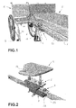
FIG. 1 is a partial perspective of a wheelchair and a bed connected together by means of a device according to the invention, -
FIG. 2 shows a perspective view of said device mounted on a portion of a track fixed at the bed, -
FIG. 3 is a top view of a preferred embodiment of the invention, -
FIG. 4 is a front view of this embodiment, -
FIG. 5 shows a first preferred embodiment of a lock plate of said device, -
FIG. 6 shows a second preferred embodiment of a lock plate of said device, and -
FIG. 7 shows a side view of a device according to the invention. - Referring to the drawings, there is shown in
FIG. 1 a perspective view of a preferred embodiment of a device 1 comprising locking means 2 and connecting means 3. As shown inFIG. 1 said device 1 is locked to a preferably tubular side frame 4 of the wheelchair 5 by said locking means 2 and connected to a bed 6 by said connecting means 3. In use, the device 1 may be fixed to the bed either at the bed-frame 7 or with other means, as a sub-chassis or an additional track as illustrated inFIGS.1 and 2 . The locking means 2 are provided with a patient release handle 8 (FIGS. 2 -3 ) which preferably is placed so that it can be easily reached from the wheelchair as well as from the bed. As shown in thefigures 1 and 2 the device 1 comprises a transfer or sliding plate 9 (FIG. 2 ) which may be adjusted to various vertical positions of the bed and the chair heights as well as the chair's horizontal position at the bed side. The wheelchair may be of the type having a tubular frame 4 supporting a seat 10 and twolarge side wheels 11, 12 for patient self-locomotion. - Referring to
FIGS. 1 and 2 , it can be seen that the transfer plate 9 may be provided with arecess 13 to accommodate the position of the transfer plate 9 to a wheel 11 of the wheelchair. - As shown in
FIG. 2 the transfer plate 9, said locking means 2 and said connecting means 3 are preferably horizontally mounted. In particular, the transfer or sliding plate 9 can be moved up/down with respect to the locking means 2 and be locked in a suitable position with the aid of two tubes 14, 141 and respective tube clamps 15, 151 (FIG. 4 ). The transfer plate 9, which serves as a transit seat for the patient, is equipped with a surface that is suitable for sitting and sliding when in use a person is transferred from the wheelchair 5 to the bed 6 or vice-versa (FIG. 1 ). - As shown in
FIG. 5 or 6 the locking means 2, which form the wheelchair lock, comprise abase plate 16 firmly fixed to a lock plate 17 (FIG. 5 ) or to a lock plate 18 (FIG. 6 ). However, thelock plate 17 or 18 and thebase plate 16 may be detachably mounted. Thelock plates 17 or 18 as shown inFIGS. 5 and 6 are connected to therespective base plate 16 by any appropriate mounting method according to the state of the art. Both lock plates have aslot 19 made to fit the tube frame of the wheel chair. A bar 20 of a resilient material like rubber (FIG. 5 ) or a claw 21 (FIG. 6 ) may be located in theslot 19 of thelock plate 17 or 18, respectively. Said claw 21 can be released by the patient release handle 8. The bar 20 is intended to press against a frame tube 4 of the wheelchair, whereas theclaw 21 may be closed behind a tube 4 of the wheelchair frame. Theclaw 21 may be designed to fit a broad range of wheelchairs, but also be replaced by special locks for wheelchairs outside this range or for other special purposes. - For convenience, an additional accessory 22 (
FIGS. 1 - 2 ) may be provided to be mounted between the bed and the device. According to the embodiment shown inFIG. 2 , said accessory may be a C-shaped track 22 fixed at the bed 6, for example by clamps or screws. InFIG. 2 thetrack 22 is shown as a C-profile having aslot 23, but it may take other forms depending on the needs of the final design, e.g. two cylindrical tubes or prismatic tracks. - The connecting means 3 comprise a slider 24 (
FIG. 7 ), so that inside thisslot 23 of thetrack 22 theslider 24 can be moved horizontally and be locked in any position by afastener handle 25. According toFIGS. 2 and4 , theslider 24 is fixed to thebase plate 16 with aid of twotubes 26, 261 andrespective tube locks 27, 271 (FIG. 4 ) which may contribute to adjust the vertical position of the transfer plate 9. However, this fixing can be of various principles depending on the concrete design of the entire ancillary device. Thefastener handle 25 may include e.g. a screw that press against the inner backside of the track or a pin that fits in holes in the back of the profile. The tube clamps 15 and/or 27 may be locks that squeeze against the tubes 14 and/or 26, respectively, as shown inFIGS. 2 and4 , but also be screws or other principles. The planes defined by thetubes 14, 141 and 26, 261 are preferably parallel. The height adjustment between the locking means 2 and the transfer plate 9 is here illustrated by means oftubes 14, 26, but other principles may be used depending of the needs of the final design. - The two
lock plates 17 and 18 shown inFIGS. 5 - 6 are examples of alternative embodiments suitable for locking the chair to the bed. As has already been said, a preferred embodiment of the invention comprises a rubber bar 20 (FIG. 5 ) pressed against the frame 4 of the wheelchair or a lock claw 21 (FIG. 6 ) which closes behind a frame tube 4 of the wheel chair frame. In this way the design of the lock plate can be changed to fit any specific wheel chair, so that the rest of the device can fix the majority of indoor wheelchairs by perhaps 2 or 3 different lock plates only, and the parameters which must be changed are simply the claw and possibly the dimension and shape of the slot (19). The ends 28 of the tubes 14, 141 (FIG. 4 ) protrude more or less throughholes plate 16 in order to adjust the vertical distance between theplate 16 and the transfer plate 9. Theplate 16 and/or theslider 24 may be provided with holes of this type such that the ends (not shown in the figures) of thetubes 26, 261 protrude more or less through at least one of said holes in order to adjust the distance between theplate 16 and theslider 24. - The invention allows the realization of a diversity of further embodiments. To give just one example, the transfer or sliding plate 9 may have a horizontal narrow prolongation having a border intended to abut against the horizontal front edge of the seat 10 of the wheelchair, so that the other end of this prolongation could rest against a preferably horizontal portion of the other side frame 30 (
FIG. 1 ) of the wheelchair, and this would drastically reduce the torque stress on the area of the connecting means 3. Alternatively, further locking means, similar to the locking means 2, could be provided for this purpose. Preferably this narrow horizontal prolongation is detachably mounted but it may also be a simple bar. This embodiments could also shaped to facilitate the patients to move themselves from the bed into the wheelchair or from the chair into the bed. -
- device 1
- locking means 2
- connecting means 3
- tubular side frame 4
- wheelchair 5
- nursing bed 6
- bed-frame 7
- patient release handle 8
- transfer or sliding plate 9
- tubular frame 4
- seat 10
- two
large side wheels 11, 12 -
recess 13 - tubes 14, 141
- tube clamps 15, 151
-
base plate 16 - lock
plate 17 or 18 -
slot 19 - bar 20
- claw 21
-
track 22 -
slot 23 -
slider 24 -
fastener handle 25 -
tubes 26, 261 - tube locks 27, 271
- end 28 of tubes 14, 141
-
holes -
tubular side frame 30
Claims (14)
- Device for assisting disabled persons to move between a wheelchair and a bed or the like, characterised in that said device comprises a transfer plate (9), locking means (2) for locking said wheelchair to the bed (5) and connecting means (3) for attaching the device at the bed (6), said locking means (2) comprising a lock plate (17, 18) provided with a slot (19) suitable to receive a frame portion (4) of the wheelchair.
- Device in accordance with claim 1, wherein the locking means (2) are provided with a patient release handle (8) which preferably is placed so that it can be easily reached from the wheelchair (5) as well as from the bed (6).
- Device in accordance with claim 1 or 2, comprising a transfer plate (9) and adjusting means to adjust the height of the transfer plate.
- Device in accordance with claim 1 or 2, comprising a transfer plate (9) and means to adjust it to various horizontal positions at the bed side relative to a position of the wheelchair.
- Device in accordance with one of the claims 1 to 4, further comprising a base plate (16), wherein the lock plate (17; 18) and said base plate (16) are separate elements which may be detachably fixed together.
- Device in accordance with one of the claims 1 to 5, wherein a locking element (20; 21) is located in said slot (19) of said the lock plate (17; 18).
- Device in accordance with claim 6, wherein said locking element (21) is a lock claw (21) which preferably can be released by the patient release handle (8).
- Device in accordance with claim 6 or 7, wherein the lock plate (17; 18) and said locking element are designed to fit a broad range of wheelchairs or to be replaced by special locks for wheelchairs outside a given range.
- Device in accordance with one of the claims 6 to 8, wherein said locking element is a bar element (20) of a resilient material, preferably rubber.
- Device according to any one of the preceding claims, wherein the lock plate is exchangeable and/or may be selected so as to temporarily attach the wheelchair to the bed.
- Device accorsing to any one of the preceding claims, wherein the conncecting means (3) are suitable to rigidly connect the device to the frame of the bed.
- Device according to any one of the preceding claims, wherein the height of the lock plate (17, 18) is adjustable.
- Device according to any one of the preceding claims, which is designed to be rigidly attached to a bed.
- Device in accordance with one of the claims 3 to 13, wherein said adjusting means comprise tubes (14, 141; 26, 261) and tube clamps (15, 151) and/or tube locks 27, 271).
Priority Applications (5)
| Application Number | Priority Date | Filing Date | Title |
|---|---|---|---|
| DK07122183.2T DK2067460T3 (en) | 2007-12-03 | 2007-12-03 | Wheelchair and bed interconnecting device |
| EP07122183A EP2067460B1 (en) | 2007-12-03 | 2007-12-03 | Device for Docking a Wheelchair to a Bed |
| AT07122183T ATE485025T1 (en) | 2007-12-03 | 2007-12-03 | DEVICE FOR DOCKING A WHEELCHAIR TO A BED |
| DE602007010012T DE602007010012D1 (en) | 2007-12-03 | 2007-12-03 | Device for docking a wheelchair to a bed |
| NO20085036A NO20085036L (en) | 2007-12-03 | 2008-12-02 | Device for docking a wheelchair for a bed |
Applications Claiming Priority (1)
| Application Number | Priority Date | Filing Date | Title |
|---|---|---|---|
| EP07122183A EP2067460B1 (en) | 2007-12-03 | 2007-12-03 | Device for Docking a Wheelchair to a Bed |
Publications (2)
| Publication Number | Publication Date |
|---|---|
| EP2067460A1 EP2067460A1 (en) | 2009-06-10 |
| EP2067460B1 true EP2067460B1 (en) | 2010-10-20 |
Family
ID=39341962
Family Applications (1)
| Application Number | Title | Priority Date | Filing Date |
|---|---|---|---|
| EP07122183A Not-in-force EP2067460B1 (en) | 2007-12-03 | 2007-12-03 | Device for Docking a Wheelchair to a Bed |
Country Status (5)
| Country | Link |
|---|---|
| EP (1) | EP2067460B1 (en) |
| AT (1) | ATE485025T1 (en) |
| DE (1) | DE602007010012D1 (en) |
| DK (1) | DK2067460T3 (en) |
| NO (1) | NO20085036L (en) |
Families Citing this family (5)
| Publication number | Priority date | Publication date | Assignee | Title |
|---|---|---|---|---|
| GB2467954C (en) * | 2009-02-20 | 2019-05-29 | Roma Medical Aids Ltd | Furniture frame |
| KR101483499B1 (en) * | 2011-08-09 | 2015-01-16 | 가부시키가이샤 티엔케이 | Apparatus for assisting moving between bed and wheelchair |
| GB201215010D0 (en) * | 2012-08-23 | 2012-10-10 | Huntleigh Technology Ltd | Leg lifter apparatus |
| KR102080545B1 (en) * | 2017-09-19 | 2020-02-24 | 연세대학교 원주산학협력단 | Wheelchair comprising mobile device |
| JP7027226B2 (en) * | 2018-03-30 | 2022-03-01 | パラマウントベッド株式会社 | Body support device |
Family Cites Families (4)
| Publication number | Priority date | Publication date | Assignee | Title |
|---|---|---|---|---|
| US1635575A (en) * | 1926-10-28 | 1927-07-12 | Cole Edwin | Transfer device for invalids |
| US4726082A (en) * | 1985-05-07 | 1988-02-23 | Nova Technologies, Inc. | Invalid transfer arrangement |
| TW434008B (en) * | 2000-08-11 | 2001-05-16 | Juang Jin Shan | Auxiliary moving apparatus for wheelchair |
| JP4074766B2 (en) * | 2002-03-04 | 2008-04-09 | 独立行政法人労働者健康福祉機構 | Wheelchair fixing device |
-
2007
- 2007-12-03 EP EP07122183A patent/EP2067460B1/en not_active Not-in-force
- 2007-12-03 AT AT07122183T patent/ATE485025T1/en not_active IP Right Cessation
- 2007-12-03 DK DK07122183.2T patent/DK2067460T3/en active
- 2007-12-03 DE DE602007010012T patent/DE602007010012D1/en active Active
-
2008
- 2008-12-02 NO NO20085036A patent/NO20085036L/en not_active Application Discontinuation
Also Published As
| Publication number | Publication date |
|---|---|
| NO20085036L (en) | 2009-06-04 |
| ATE485025T1 (en) | 2010-11-15 |
| EP2067460A1 (en) | 2009-06-10 |
| DE602007010012D1 (en) | 2010-12-02 |
| DK2067460T3 (en) | 2011-11-07 |
Similar Documents
| Publication | Publication Date | Title |
|---|---|---|
| EP1613524B1 (en) | Center-of-gravity tilt-in-space wheelchair | |
| AU2008246371B2 (en) | Method and apparatus for transferring a wheelchair bound person | |
| US6257664B1 (en) | Multiple adjustable back assembly for use with wheelchair | |
| US7487558B2 (en) | Headboard for a pull-up-in-bed system | |
| US5228747A (en) | Seating system | |
| US6857149B2 (en) | Sleep support system | |
| US10272005B2 (en) | Bedside assistant and its attachment to a bed | |
| US5366277A (en) | Modular pediatric seating system | |
| EP2067460A1 (en) | Device for Docking a Wheelchair to a Bed | |
| US8403420B2 (en) | Reversible footrest | |
| US20120198628A1 (en) | Manually removable foot section | |
| US6460927B1 (en) | Support assembly for use with wheelchair | |
| CA1241902A (en) | Supporting device for wheelchairs | |
| US9737120B2 (en) | Mobility device | |
| WO2020061493A1 (en) | Detachable bed rail | |
| JP2016517713A (en) | Bath chair for the physically disabled | |
| US20070186348A1 (en) | Providing mobility support | |
| EP3914217B1 (en) | Transfer assist pull handles and methods of use thereof | |
| US7188902B1 (en) | Backupholstery adjustment device for wheelchair | |
| US8973938B2 (en) | Universal foot tray for wheelchairs | |
| EP2709491B1 (en) | Lateral support apparatus for a chair | |
| KR20190031963A (en) | A mobile device installed in a wheelchair and wheelchair comprising thereof | |
| US20170252240A1 (en) | Back support attachment and adjustment assembly for a wheelchair | |
| US7854481B2 (en) | Methods and apparatus for assembling a wheel chair | |
| WO2004098480A1 (en) | Calf rest for patient chair |
Legal Events
| Date | Code | Title | Description |
|---|---|---|---|
| PUAI | Public reference made under article 153(3) epc to a published international application that has entered the european phase |
Free format text: ORIGINAL CODE: 0009012 |
|
| AK | Designated contracting states |
Kind code of ref document: A1 Designated state(s): AT BE BG CH CY CZ DE DK EE ES FI FR GB GR HU IE IS IT LI LT LU LV MC MT NL PL PT RO SE SI SK TR |
|
| AX | Request for extension of the european patent |
Extension state: AL BA HR MK RS |
|
| 17P | Request for examination filed |
Effective date: 20091104 |
|
| AKX | Designation fees paid |
Designated state(s): AT BE BG CH CY CZ DE DK EE ES FI FR GB GR HU IE IS IT LI LT LU LV MC MT NL PL PT RO SE SI SK TR |
|
| GRAP | Despatch of communication of intention to grant a patent |
Free format text: ORIGINAL CODE: EPIDOSNIGR1 |
|
| GRAS | Grant fee paid |
Free format text: ORIGINAL CODE: EPIDOSNIGR3 |
|
| GRAA | (expected) grant |
Free format text: ORIGINAL CODE: 0009210 |
|
| AK | Designated contracting states |
Kind code of ref document: B1 Designated state(s): AT BE BG CH CY CZ DE DK EE ES FI FR GB GR HU IE IS IT LI LT LU LV MC MT NL PL PT RO SE SI SK TR |
|
| REG | Reference to a national code |
Ref country code: GB Ref legal event code: FG4D |
|
| REG | Reference to a national code |
Ref country code: CH Ref legal event code: EP |
|
| REG | Reference to a national code |
Ref country code: CH Ref legal event code: NV Representative=s name: ABREMA AGENCE BREVET ET MARQUES, GANGUILLET |
|
| REG | Reference to a national code |
Ref country code: IE Ref legal event code: FG4D |
|
| REF | Corresponds to: |
Ref document number: 602007010012 Country of ref document: DE Date of ref document: 20101202 Kind code of ref document: P |
|
| REG | Reference to a national code |
Ref country code: NL Ref legal event code: T3 |
|
| LTIE | Lt: invalidation of european patent or patent extension |
Effective date: 20101020 |
|
| PG25 | Lapsed in a contracting state [announced via postgrant information from national office to epo] |
Ref country code: LT Free format text: LAPSE BECAUSE OF FAILURE TO SUBMIT A TRANSLATION OF THE DESCRIPTION OR TO PAY THE FEE WITHIN THE PRESCRIBED TIME-LIMIT Effective date: 20101020 |
|
| PG25 | Lapsed in a contracting state [announced via postgrant information from national office to epo] |
Ref country code: IS Free format text: LAPSE BECAUSE OF FAILURE TO SUBMIT A TRANSLATION OF THE DESCRIPTION OR TO PAY THE FEE WITHIN THE PRESCRIBED TIME-LIMIT Effective date: 20110220 Ref country code: LV Free format text: LAPSE BECAUSE OF FAILURE TO SUBMIT A TRANSLATION OF THE DESCRIPTION OR TO PAY THE FEE WITHIN THE PRESCRIBED TIME-LIMIT Effective date: 20101020 Ref country code: BG Free format text: LAPSE BECAUSE OF FAILURE TO SUBMIT A TRANSLATION OF THE DESCRIPTION OR TO PAY THE FEE WITHIN THE PRESCRIBED TIME-LIMIT Effective date: 20110120 Ref country code: AT Free format text: LAPSE BECAUSE OF FAILURE TO SUBMIT A TRANSLATION OF THE DESCRIPTION OR TO PAY THE FEE WITHIN THE PRESCRIBED TIME-LIMIT Effective date: 20101020 Ref country code: PT Free format text: LAPSE BECAUSE OF FAILURE TO SUBMIT A TRANSLATION OF THE DESCRIPTION OR TO PAY THE FEE WITHIN THE PRESCRIBED TIME-LIMIT Effective date: 20110221 Ref country code: SE Free format text: LAPSE BECAUSE OF FAILURE TO SUBMIT A TRANSLATION OF THE DESCRIPTION OR TO PAY THE FEE WITHIN THE PRESCRIBED TIME-LIMIT Effective date: 20101020 Ref country code: SI Free format text: LAPSE BECAUSE OF FAILURE TO SUBMIT A TRANSLATION OF THE DESCRIPTION OR TO PAY THE FEE WITHIN THE PRESCRIBED TIME-LIMIT Effective date: 20101020 Ref country code: FI Free format text: LAPSE BECAUSE OF FAILURE TO SUBMIT A TRANSLATION OF THE DESCRIPTION OR TO PAY THE FEE WITHIN THE PRESCRIBED TIME-LIMIT Effective date: 20101020 |
|
| PG25 | Lapsed in a contracting state [announced via postgrant information from national office to epo] |
Ref country code: BE Free format text: LAPSE BECAUSE OF FAILURE TO SUBMIT A TRANSLATION OF THE DESCRIPTION OR TO PAY THE FEE WITHIN THE PRESCRIBED TIME-LIMIT Effective date: 20101020 Ref country code: GR Free format text: LAPSE BECAUSE OF FAILURE TO SUBMIT A TRANSLATION OF THE DESCRIPTION OR TO PAY THE FEE WITHIN THE PRESCRIBED TIME-LIMIT Effective date: 20110121 |
|
| PG25 | Lapsed in a contracting state [announced via postgrant information from national office to epo] |
Ref country code: MC Free format text: LAPSE BECAUSE OF NON-PAYMENT OF DUE FEES Effective date: 20101231 Ref country code: CZ Free format text: LAPSE BECAUSE OF FAILURE TO SUBMIT A TRANSLATION OF THE DESCRIPTION OR TO PAY THE FEE WITHIN THE PRESCRIBED TIME-LIMIT Effective date: 20101020 Ref country code: ES Free format text: LAPSE BECAUSE OF FAILURE TO SUBMIT A TRANSLATION OF THE DESCRIPTION OR TO PAY THE FEE WITHIN THE PRESCRIBED TIME-LIMIT Effective date: 20110131 Ref country code: EE Free format text: LAPSE BECAUSE OF FAILURE TO SUBMIT A TRANSLATION OF THE DESCRIPTION OR TO PAY THE FEE WITHIN THE PRESCRIBED TIME-LIMIT Effective date: 20101020 |
|
| PLBE | No opposition filed within time limit |
Free format text: ORIGINAL CODE: 0009261 |
|
| STAA | Information on the status of an ep patent application or granted ep patent |
Free format text: STATUS: NO OPPOSITION FILED WITHIN TIME LIMIT |
|
| PG25 | Lapsed in a contracting state [announced via postgrant information from national office to epo] |
Ref country code: DK Free format text: LAPSE BECAUSE OF FAILURE TO SUBMIT A TRANSLATION OF THE DESCRIPTION OR TO PAY THE FEE WITHIN THE PRESCRIBED TIME-LIMIT Effective date: 20101020 Ref country code: SK Free format text: LAPSE BECAUSE OF FAILURE TO SUBMIT A TRANSLATION OF THE DESCRIPTION OR TO PAY THE FEE WITHIN THE PRESCRIBED TIME-LIMIT Effective date: 20101020 Ref country code: PL Free format text: LAPSE BECAUSE OF FAILURE TO SUBMIT A TRANSLATION OF THE DESCRIPTION OR TO PAY THE FEE WITHIN THE PRESCRIBED TIME-LIMIT Effective date: 20101020 Ref country code: RO Free format text: LAPSE BECAUSE OF FAILURE TO SUBMIT A TRANSLATION OF THE DESCRIPTION OR TO PAY THE FEE WITHIN THE PRESCRIBED TIME-LIMIT Effective date: 20101020 |
|
| REG | Reference to a national code |
Ref country code: SE Ref legal event code: RINS |
|
| REG | Reference to a national code |
Ref country code: SE Ref legal event code: TRGR |
|
| 26N | No opposition filed |
Effective date: 20110721 |
|
| REG | Reference to a national code |
Ref country code: DK Ref legal event code: EGE |
|
| PG25 | Lapsed in a contracting state [announced via postgrant information from national office to epo] |
Ref country code: IE Free format text: LAPSE BECAUSE OF NON-PAYMENT OF DUE FEES Effective date: 20101203 |
|
| REG | Reference to a national code |
Ref country code: DK Ref legal event code: T3 |
|
| REG | Reference to a national code |
Ref country code: DE Ref legal event code: R097 Ref document number: 602007010012 Country of ref document: DE Effective date: 20110721 |
|
| PG25 | Lapsed in a contracting state [announced via postgrant information from national office to epo] |
Ref country code: IT Free format text: LAPSE BECAUSE OF FAILURE TO SUBMIT A TRANSLATION OF THE DESCRIPTION OR TO PAY THE FEE WITHIN THE PRESCRIBED TIME-LIMIT Effective date: 20101020 Ref country code: MT Free format text: LAPSE BECAUSE OF FAILURE TO SUBMIT A TRANSLATION OF THE DESCRIPTION OR TO PAY THE FEE WITHIN THE PRESCRIBED TIME-LIMIT Effective date: 20101020 |
|
| REG | Reference to a national code |
Ref country code: CH Ref legal event code: PL |
|
| PG25 | Lapsed in a contracting state [announced via postgrant information from national office to epo] |
Ref country code: CY Free format text: LAPSE BECAUSE OF FAILURE TO SUBMIT A TRANSLATION OF THE DESCRIPTION OR TO PAY THE FEE WITHIN THE PRESCRIBED TIME-LIMIT Effective date: 20101020 |
|
| PG25 | Lapsed in a contracting state [announced via postgrant information from national office to epo] |
Ref country code: LU Free format text: LAPSE BECAUSE OF NON-PAYMENT OF DUE FEES Effective date: 20101203 Ref country code: HU Free format text: LAPSE BECAUSE OF FAILURE TO SUBMIT A TRANSLATION OF THE DESCRIPTION OR TO PAY THE FEE WITHIN THE PRESCRIBED TIME-LIMIT Effective date: 20110421 |
|
| PG25 | Lapsed in a contracting state [announced via postgrant information from national office to epo] |
Ref country code: LI Free format text: LAPSE BECAUSE OF NON-PAYMENT OF DUE FEES Effective date: 20111231 Ref country code: CH Free format text: LAPSE BECAUSE OF NON-PAYMENT OF DUE FEES Effective date: 20111231 Ref country code: TR Free format text: LAPSE BECAUSE OF FAILURE TO SUBMIT A TRANSLATION OF THE DESCRIPTION OR TO PAY THE FEE WITHIN THE PRESCRIBED TIME-LIMIT Effective date: 20101020 |
|
| PGRI | Patent reinstated in contracting state [announced from national office to epo] |
Ref country code: SE Effective date: 20110902 |
|
| REG | Reference to a national code |
Ref country code: FR Ref legal event code: PLFP Year of fee payment: 9 |
|
| PGFP | Annual fee paid to national office [announced via postgrant information from national office to epo] |
Ref country code: DE Payment date: 20151211 Year of fee payment: 9 Ref country code: DK Payment date: 20151221 Year of fee payment: 9 Ref country code: GB Payment date: 20151221 Year of fee payment: 9 |
|
| PGFP | Annual fee paid to national office [announced via postgrant information from national office to epo] |
Ref country code: SE Payment date: 20151221 Year of fee payment: 9 Ref country code: FR Payment date: 20151221 Year of fee payment: 9 Ref country code: NL Payment date: 20151221 Year of fee payment: 9 |
|
| REG | Reference to a national code |
Ref country code: DE Ref legal event code: R119 Ref document number: 602007010012 Country of ref document: DE |
|
| REG | Reference to a national code |
Ref country code: DK Ref legal event code: EBP Effective date: 20161231 |
|
| REG | Reference to a national code |
Ref country code: SE Ref legal event code: EUG |
|
| REG | Reference to a national code |
Ref country code: NL Ref legal event code: MM Effective date: 20170101 |
|
| GBPC | Gb: european patent ceased through non-payment of renewal fee |
Effective date: 20161203 |
|
| PG25 | Lapsed in a contracting state [announced via postgrant information from national office to epo] |
Ref country code: SE Free format text: LAPSE BECAUSE OF FAILURE TO SUBMIT A TRANSLATION OF THE DESCRIPTION OR TO PAY THE FEE WITHIN THE PRESCRIBED TIME-LIMIT Effective date: 20161204 |
|
| PG25 | Lapsed in a contracting state [announced via postgrant information from national office to epo] |
Ref country code: NL Free format text: LAPSE BECAUSE OF NON-PAYMENT OF DUE FEES Effective date: 20170101 |
|
| REG | Reference to a national code |
Ref country code: FR Ref legal event code: ST Effective date: 20170831 |
|
| PG25 | Lapsed in a contracting state [announced via postgrant information from national office to epo] |
Ref country code: FR Free format text: LAPSE BECAUSE OF NON-PAYMENT OF DUE FEES Effective date: 20170102 |
|
| PG25 | Lapsed in a contracting state [announced via postgrant information from national office to epo] |
Ref country code: DE Free format text: LAPSE BECAUSE OF NON-PAYMENT OF DUE FEES Effective date: 20170701 Ref country code: GB Free format text: LAPSE BECAUSE OF NON-PAYMENT OF DUE FEES Effective date: 20161203 |
|
| PG25 | Lapsed in a contracting state [announced via postgrant information from national office to epo] |
Ref country code: DK Free format text: LAPSE BECAUSE OF FAILURE TO SUBMIT A TRANSLATION OF THE DESCRIPTION OR TO PAY THE FEE WITHIN THE PRESCRIBED TIME-LIMIT Effective date: 20161231 |