EP2067006B1 - Gammamètre compact - Google Patents
Gammamètre compact Download PDFInfo
- Publication number
- EP2067006B1 EP2067006B1 EP07808617.0A EP07808617A EP2067006B1 EP 2067006 B1 EP2067006 B1 EP 2067006B1 EP 07808617 A EP07808617 A EP 07808617A EP 2067006 B1 EP2067006 B1 EP 2067006B1
- Authority
- EP
- European Patent Office
- Prior art keywords
- source
- housing
- instrument according
- detector
- pipe
- Prior art date
- Legal status (The legal status is an assumption and is not a legal conclusion. Google has not performed a legal analysis and makes no representation as to the accuracy of the status listed.)
- Active
Links
Images
Classifications
-
- G—PHYSICS
- G01—MEASURING; TESTING
- G01N—INVESTIGATING OR ANALYSING MATERIALS BY DETERMINING THEIR CHEMICAL OR PHYSICAL PROPERTIES
- G01N9/00—Investigating density or specific gravity of materials; Analysing materials by determining density or specific gravity
- G01N9/24—Investigating density or specific gravity of materials; Analysing materials by determining density or specific gravity by observing the transmission of wave or particle radiation through the material
Definitions
- This invention relates to a gamma-ray flow measuring instrument for measuring the density of a fluid in a volume in a container, especially in a fluid flow in a pipe or similar. More specific the invention relates to a construction where a source and detector are partially inserted into the pipe wall and the pipe opening area has a conical shape so as to reduce the vulnerability of the pipe wall and at the same time let the source come as close as possible to the detector.
- gamma sources are often used. These are based on positioning a gamma source and detector on opposite sides of the flow and measuring the differences in detector signal depending on the density of the flow.
- the present systems often require the use of high activity gamma sources of the Cs137 type in the range of 1100-1900kBq (30-50mCurie) and energies in the range of 660keV, and thus requires special handling of radioactive materials in addition to constituting large units to be mounted on the pipe.
- the object of the present invention is to provide a more compact solution which provides sufficiently good measurements and also requires gamma sources with lower activity. This is obtained with an instrument as specified in the independent claims.
- WO97/29356A WO2006/067525 and GB 2325735 propose solutions where the source penetrates the wall completely and thus weakens the wall.
- WO2006/06752 shows a conical source holder, the cone extends into the fluid and thus has a different function than in the present invention.
- the gamma source is inserted into a recess in the pipe wall corresponding to the outer shape of the source housing.
- the source housing may be constituted by an outer lead filled steel housing or titanium housing with a tungsten or steel core or source holder including the gamma source preferably positioned coaxially therein.
- the core or holder also includes a channel from the embedded gamma point source toward the pipe centre. Coaxial with the core and channel a conical protrusion is provided surrounding an extension of the channel and forming a point into a corresponding cavity in the centre of the recess in the pipe wall.
- the recess is made into the pipe wall leaving a part of the pipe wall between the top of the core and the flow.
- the source emits relatively high energy radiation, e.g. a Cs137 source, which results in a requirement for the source housing to provide a good shielding, e.g. being made from lead or a lead filled steel casing with a tungsten core.
- the line between the source and detector has an angle relative to the flow axis.
- This is advantageous because a longer propagation path provides improved measurement sensitivity as the wet gas otherwise has too low attenuation at the relevant photon energies.
- an Am241 source may be placed in a steel core and e.g. having titanium housing, and the pipe wall is replaced by a portion of e.g. a PEEK material low attenuation of the gamma radiation and also being capable of withstanding the conditions in the flow.
- a detector is inserted in a suitable recess, preferably having a cavity in front of the detector with a smaller diameter to reduce the material thickness of the pipe directly between the detector and the flow.
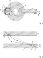
- FIG. 1 illustrates a gamma instrument mounted in a pipe 1.
- the pipe 1 is made from steel and in addition the illustrated pipe comprises a PEEK (polyetheretherketone) material 3 on its inner surface.
- PEEK polyetheretherketone
- the latter may be required if the gamma instrument is combined with other measuring instruments, e.g. with electrodes in contact with the flow, but is not important to the present invention.
- PEEK is often used in relation to multiphase hydrocarbon flows because of its mechanical durability, and chemical neutrality in combination with the components in the flow in varying temperatures.
- a gamma source housing 2 is positioned in a recess in the pipe wall and being fastened therein by any available means.
- the housing and recess is also sealed O-rings 8 to avoid leaks through the recess.
- the housing 2 is preferably made from a high density material like lead, but in some cases, e.g. when using less active gamma sources, steel may be used.
- a lead filled 5 steel housing 2 is shown.
- the source 4 is positioned in a core or source holder 7 positioned coaxially in the housing, and this core has a channel from the source toward the flow inside the pipe.
- the core may be of different types of relatively high density materials but in the illustrated example the core is made from Tungsten or other absorbing materials, and with less active sources a combination of steel housing and enlarged Tungsten core may be used.
- the thickness through the material is as small as possible, but without weakening the pipe wall.
- This conical shape provides a sharp beam cross section as it provides a long channel through the absorbing material, but does not weaken the wall in the same degree as would be the case if the core had the same cross section along its length.
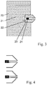
- the essentially conical shape of the tip 10 may in practice deviate from the smooth cone, e.g. due to machining considerations, for example in a stepwise reduction of the radius toward the end of the tip, as is illustrated in figure 4 .
- the preferred source 4 in this embodiment is a Cs 137 source, preferably in the range of 3.7-37 x 10 7 Becquerel (1-10 mCurie), especially 18.5 x 10 7 Becquerel (5mCurie).
- FIG 3 illustrates an alternative embodiment of the source housing and core, where the housing 2 is provided as a steel shell 20 enclosing a Tungsten inner part 21, and in which the core/source holder 22 is also made from Tungsten.
- the core 22 is mounted into the inner part 21 by a threaded coupling 23, and the source 24 is incorporated in the source holder 22.
- the detector 9 which may be on any suitable type, is positioned in a recess in the pipe wall on the other side of the flow.
- the energy being detected is in the range of range ⁇ 660eV, as lower energies from the source will be absorbed by the steel in the pipe wall.
- a cavity is also provided in front of the detector 9 to reduce the wall thickness in front of the detector, thus to reduce the attenuation in front of the detector.
- the pipe wall in front of the detector and the source is approximately 5mm, but this may be chosen according to the specific use of the instrument.
- the detector is positioned on the opposite side of the flow relative to the source.
- the detector may also be provided with a frustoconical shape in order to reduce the weakening of the pipe wall.
- Other configurations may be contemplated, such as several detectors positioned off the beam axis for detecting radiation scattered from the flow, as discussed in Norwegian patent application No. 1999.2988 for the purpose of obtaining salinity independent density measurement in the flow.
- the radiation may be transmitted directly from the one or more sources through different parts of the flow. This way it will be possible to provide measurements of the density on the flow centre as well as close to the pipe wall, so as to make it possible to detect a layered structure where different fluids are found at different distances from the flow centre.
- a radiation beam aimed at measuring close to pipe wall will both leave and enter the pipe wall at an angle.
- the detector and source housing has to be positioned at a distance from the inner pipe wall so as not to weaken the wall.
- the beam has to leave the wall at an angle this also means that it in these cases has to propagate through more pipe wall material before entering the flow.
- a cavity may be provided into the inner pipe wall so as to reduce the propagation length through the pipe wall, and this cavity may be filled with a material being relatively transparent to the radiation, e.g. PEEK material.
- FIG 2 A related solution is illustrated in figure 2 , where the beam has an angle relative to the flow direction and the pipe wall.
- the gamma beam may also be aimed at an angle relative to the flow. This is especially suitable when measuring the density of wet gas flows, where the fluid has a low attenuation rate and the sensitivity may be increased by increasing the propagation length through the fluid flow.
- the angle will depend on the attenuation in the flow and sensitivity of the detector relative to the beam energy, but will usually be below 75 degrees so as to obtain a significant increase in the beam path length.
- a source 14 with lower energy may be used, such as Am241, thus requiring a reduced wall thickness to avoid too much attenuation in the steel pipe walls 1.
- this is solved by constructing the recess by making a hole through the pipe wall and positioning the source housing in the outer parts of this opening, and sealing it for avoiding leaks though the opening in any suitable way being available for a person skilled in the art, e.g. by using O-rings as illustrated in the drawings.
- a recess is left in the inner pipe wall.
- a window 13 for the gamma radiation e.g.
- the source housing 12 is made from an outer casing 15 of a low density materials such as titanium alloys with a steel core 17 containing the source 14.
- the core protrudes with a conical shape 16 toward the flow, but in this case the housing 12 covers the tip of the cone and provides a wall for the gamma rays in the outer end of the channel closest to the flow, so as to protect the source from interactions with leaks etc from the flow passing the peek material 13.
- the housing 12 may have a thickness of 5mm on front of the cone 16.
- Titanium alloys are especially advantageous in this application as it combines mechanical strength with low attenuation, thus acting as a window for the radiation in front of the cone opening. This could also be solved with a thin steel plate in the end of the channel, at the cost of mechanical strength or increased absorption.
- an Am241 source in the range of 180-1100 x 10 7 Becquerel (50-300mCurie) is used and a detector 19 suitable for detecting in the energy range of ⁇ 59,5keV is preferred.
- the embodiments disclosed in figures 1 and 2 are suitable for different applications.
- the compact gamma density measuring instrument illustrated in figure 1 represents the preferred embodiment in situations where the flow is a multiphase flow comprising e.g. oil, water and gas.
- the source and detector is positioned directly opposite each other with a beam having a 90° angle relative to the fluid flow direction.
- the gamma density measuring instrument in figure 2 represents a preferred embodiment in the case where the flow is constituted by wet gas, i.e. mainly gas with some contributions of water and/or oil.
- the invention is aimed at providing a compact solution providing good dynamical range of measurements performed without using strong gamma sources.
- this invention is mainly adapted to measurements in pipes containing fluid flows passing the measuring instrument it may also be used for containers containing fluids, e.g. for measuring the density of a pressurized fluid inside a tank.
Landscapes
- Physics & Mathematics (AREA)
- Health & Medical Sciences (AREA)
- Life Sciences & Earth Sciences (AREA)
- Chemical & Material Sciences (AREA)
- Analytical Chemistry (AREA)
- Biochemistry (AREA)
- General Health & Medical Sciences (AREA)
- General Physics & Mathematics (AREA)
- Immunology (AREA)
- Pathology (AREA)
- Analysing Materials By The Use Of Radiation (AREA)
- Measurement Of Radiation (AREA)
Claims (12)
- Instrument de mesure de densité compact pour mesurer la densité de fluides dans un volume dans un récipient (1), en particulier dans un écoulement de fluide dans un tuyau (1), la paroi de récipient comprenant une cavité ayant une profondeur inférieure à l'épaisseur de la paroi de récipient, l'instrument comprenant une source de rayonnement (4) dans la plage gamma positionnée d'un côté du fluide et un détecteur (9) positionné du côté opposé du fluide pour recevoir ledit rayonnement, et le fluide étant contenu dans le récipient (1),
dans lequel la source (4) est positionnée dans un boîtier de source, ledit boîtier de source étant au moins partiellement ajusté dans la cavité dans la paroi de récipient, ledit boîtier de source (2) comprenant un support de source (7) contenant la source de gamma dans l'axe de support et comprenant un canal à partir de la source à travers une première extrémité du support (7), ladite première extrémité étant adaptée pour être dirigée vers le fluide,
dans lequel la partie externe de ladite première extrémité du support de source est une pointe de forme conique (10) agencée sur le support de source (7) qui fait saillie dans la paroi de tuyau dans laquelle le canal dans le noyau s'étend à travers le support de source et vers l'extérieur à partir de la pointe (10), en faisant ainsi saillie vers le fluide et étant adaptée pour s'ajuster dans ladite cavité correspondante dans la paroi de récipient, en laissant ainsi une partie de la paroi de récipient entre le sommet de la pointe (10) et le fluide. - Instrument selon la revendication 1, dans lequel le détecteur (9) est positionné dans un boîtier de détecteur ajusté dans un évidement dans le récipient à paroi (1) sur le côté opposé du fluide par rapport à la source (4).
- Instrument selon la revendication 1, dans lequel le support de source est fabriqué à partir d'un matériau de densité relativement élevée, par exemple en tungstène.
- Instrument selon la revendication 1, dans lequel ledit support de source est monté dans un boîtier en matériau de densité élevée, par exemple fabriqué en plomb, ledit boîtier étant adapté pour être fixé au récipient.
- Instrument selon la revendication 1, dans lequel le récipient est une section de tuyau adaptée pour être montée dans une canalisation.
- Instrument selon la revendication 1, dans lequel la source est une source de Cs-137 gamma.
- Instrument selon la revendication 1, dans lequel l'axe de faisceau entre la source 4 et le détecteur (9) a un angle par rapport à l'axe de tuyau inférieur à 90 degrés.
- Instrument selon la revendication 7, dans lequel le support de source contenant la source de gamma est réalisé en métal, par exemple en acier.
- Instrument selon la revendication 8, dans lequel ledit boîtier de source est fabriqué à partir d'un matériau à faible densité, par exemple un alliage de titane.
- Instrument selon la revendication 7, dans lequel le détecteur (9) est contenu dans un boîtier de détecteur ajusté dans un évidement dans la paroi de tuyau du côté opposé à la source.
- Instrument selon la revendication 7, dans lequel la source est une source de gamma de faible énergie, par exemple Am-241.
- Instrument selon la revendication 7, dans lequel ledit détecteur est également positionné dans une ouverture dans la paroi de tuyau et a une partie avant qui est retirée d'une surface de tuyau interne, et un matériau étant essentiellement transparent au rayonnement gamma, par exemple Peek, étant positionné entre le boîtier et la surface de tuyau interne, le matériau transparent représentant ainsi un prolongement essentiellement continu de la surface de tuyau.
Applications Claiming Priority (2)
| Application Number | Priority Date | Filing Date | Title |
|---|---|---|---|
| NO20063846A NO328909B1 (no) | 2006-08-29 | 2006-08-29 | Kompakt gammabasert tetthetsmaleinstrument |
| PCT/NO2007/000303 WO2008026935A1 (fr) | 2006-08-29 | 2007-08-28 | Gammamètre compact |
Publications (2)
| Publication Number | Publication Date |
|---|---|
| EP2067006A1 EP2067006A1 (fr) | 2009-06-10 |
| EP2067006B1 true EP2067006B1 (fr) | 2018-08-15 |
Family
ID=38657779
Family Applications (1)
| Application Number | Title | Priority Date | Filing Date |
|---|---|---|---|
| EP07808617.0A Active EP2067006B1 (fr) | 2006-08-29 | 2007-08-28 | Gammamètre compact |
Country Status (5)
| Country | Link |
|---|---|
| US (1) | US7978815B2 (fr) |
| EP (1) | EP2067006B1 (fr) |
| DK (1) | DK2067006T3 (fr) |
| NO (1) | NO328909B1 (fr) |
| WO (2) | WO2008026936A1 (fr) |
Families Citing this family (7)
| Publication number | Priority date | Publication date | Assignee | Title |
|---|---|---|---|---|
| WO2011068888A1 (fr) * | 2009-12-01 | 2011-06-09 | Schlumberger Technology Corp. | Fenetre de densitometre gamma pre-contrainte et son procede de fabrication |
| GB2490685B (en) | 2011-05-10 | 2017-05-24 | Salunda Ltd | Fluid conduit |
| JP6595379B2 (ja) * | 2015-11-04 | 2019-10-23 | 富士電機株式会社 | 配管選別装置、配管選別方法及び配管測位システム |
| US10890544B1 (en) * | 2019-12-18 | 2021-01-12 | Field Service Solutions LLC | Nuclear densitometer assemblies for hydraulic fracturing |
| CN112097844A (zh) * | 2020-09-12 | 2020-12-18 | 江苏万宝电子有限公司 | 一种高精度计量蒸汽流量计 |
| CN112229762A (zh) * | 2020-11-06 | 2021-01-15 | 南京愚工智能技术有限公司 | 一种管道内流体密度测量方法和密度测量安装结构 |
| NO20240551A1 (en) | 2024-05-30 | 2025-12-01 | Roxar Flow Measurement As | Tomography powered fast gamma |
Family Cites Families (12)
| Publication number | Priority date | Publication date | Assignee | Title |
|---|---|---|---|---|
| US3787683A (en) * | 1972-05-24 | 1974-01-22 | Weston Instruments Inc | Radiation gauge for measuring fluid densities |
| DE2817018C2 (de) * | 1978-04-19 | 1985-12-19 | Kernforschungszentrum Karlsruhe Gmbh, 7500 Karlsruhe | Vorrichtung zur Messung der Dichte einer Ein- oder Mehrphasenströmung |
| US4352288A (en) * | 1980-07-24 | 1982-10-05 | Texaco Inc. | Measurement of salt content in petroleum flow lines |
| GB2144214B (en) * | 1983-07-27 | 1986-10-22 | Hri Inc | Fluid velocity and metal concentration meter system and method using mossbauer effect |
| GB8526413D0 (en) * | 1985-10-25 | 1985-11-27 | Atomic Energy Authority Uk | Analysis of fluid |
| CA1290866C (fr) | 1986-11-25 | 1991-10-15 | Doug I. Exall | Dispositif d'analyse d'un fluide dans une tuyauterie |
| EP0879410A1 (fr) * | 1996-02-07 | 1998-11-25 | Biotraces, Inc. | Procede et appareil de telemesure de densite |
| FR2764064B1 (fr) | 1997-05-30 | 1999-07-16 | Schlumberger Services Petrol | Section d'ecoulement pour les mesures concernant les effluents de puits petrolier et systeme de mesure comprenant une telle section |
| EP1218728A1 (fr) | 1999-10-04 | 2002-07-03 | Daniel Industries, Inc., | Appareil et procede permettant de determiner les caracteristiques des effluents de puits de petrole dans des conditions d'ecoulement non homogenes |
| AU2001212268A1 (en) | 2000-10-23 | 2002-05-06 | Halliburton Energy Services, Inc. | Fluid property sensors and associated methods of calibrating sensors in a subterranean well |
| AUPR751101A0 (en) | 2001-09-06 | 2001-09-27 | Commonwealth Scientific And Industrial Research Organisation | Density and level gauges |
| GB0428193D0 (en) | 2004-12-23 | 2005-01-26 | Johnson Matthey Plc | Density measuring apparatus |
-
2006
- 2006-08-29 NO NO20063846A patent/NO328909B1/no unknown
-
2007
- 2007-08-28 DK DK07808617.0T patent/DK2067006T3/en active
- 2007-08-28 WO PCT/NO2007/000304 patent/WO2008026936A1/fr not_active Ceased
- 2007-08-28 EP EP07808617.0A patent/EP2067006B1/fr active Active
- 2007-08-28 US US12/377,311 patent/US7978815B2/en active Active
- 2007-08-28 WO PCT/NO2007/000303 patent/WO2008026935A1/fr not_active Ceased
Non-Patent Citations (1)
| Title |
|---|
| None * |
Also Published As
| Publication number | Publication date |
|---|---|
| EP2067006A1 (fr) | 2009-06-10 |
| WO2008026935A1 (fr) | 2008-03-06 |
| US7978815B2 (en) | 2011-07-12 |
| NO328909B1 (no) | 2010-06-14 |
| WO2008026936A1 (fr) | 2008-03-06 |
| NO20063846L (no) | 2008-03-03 |
| DK2067006T3 (en) | 2018-11-26 |
| US20100065730A1 (en) | 2010-03-18 |
Similar Documents
| Publication | Publication Date | Title |
|---|---|---|
| EP2067006B1 (fr) | Gammamètre compact | |
| JP4624399B2 (ja) | ガンマ後方散乱による密度測定 | |
| DE102011080549B4 (de) | Optimale Detektorposition für einen Gamma-Rückstrahler | |
| EP2169389B1 (fr) | Jauge de densité nucléaire à puits unique | |
| US20130113500A1 (en) | Fill-level measuring device for ascertaining and monitoring fill level of a medium located in the process space of a container by means of a microwave travel time measuring method | |
| NO326853B1 (no) | System og fremgangsmåte for logging-under-boring ved hjelp av radioaktiv strålingskilde | |
| CA2203270A1 (fr) | Outil de diagraphie de la densite des formations dans les trous tubes ou non | |
| CN107076871A (zh) | 气井完整性检查系统 | |
| CA1314244C (fr) | Methode pour l'assemblage d'une piece metallique et d'un tube haute pression en materiau composite, utilisable dans l'industrie petroliere | |
| AU2014372313B2 (en) | Scanning instrument | |
| US20180292566A1 (en) | Radiation source device having fluorescent material for secondary photon generation | |
| US11098574B2 (en) | Sensor with integrated window | |
| EP3025143B1 (fr) | Dispositif de retenue destiné à retenir un réflecteur et un dispositif de guidage électromagnétique | |
| US9989510B2 (en) | Flow cell as well as a system and a method for analysing a fluid | |
| CN116457638B (zh) | 用于放射测量的测量装置的辐射防护容器 | |
| FR2564598A1 (fr) | Sonde de mesure de corrosion de canalisations | |
| CN2737943Y (zh) | 低能伽玛源流体密度测井仪的探测装置 | |
| JP2006308401A (ja) | 腐蝕性ガス分析センサー | |
| US11561159B2 (en) | Radiometric density measurement |
Legal Events
| Date | Code | Title | Description |
|---|---|---|---|
| PUAI | Public reference made under article 153(3) epc to a published international application that has entered the european phase |
Free format text: ORIGINAL CODE: 0009012 |
|
| 17P | Request for examination filed |
Effective date: 20090327 |
|
| AK | Designated contracting states |
Kind code of ref document: A1 Designated state(s): AT BE BG CH CY CZ DE DK EE ES FI FR GB GR HU IE IS IT LI LT LU LV MC MT NL PL PT RO SE SI SK TR |
|
| AX | Request for extension of the european patent |
Extension state: AL BA HR MK RS |
|
| DAX | Request for extension of the european patent (deleted) | ||
| 17Q | First examination report despatched |
Effective date: 20140626 |
|
| GRAP | Despatch of communication of intention to grant a patent |
Free format text: ORIGINAL CODE: EPIDOSNIGR1 |
|
| INTG | Intention to grant announced |
Effective date: 20180424 |
|
| GRAS | Grant fee paid |
Free format text: ORIGINAL CODE: EPIDOSNIGR3 |
|
| GRAA | (expected) grant |
Free format text: ORIGINAL CODE: 0009210 |
|
| AK | Designated contracting states |
Kind code of ref document: B1 Designated state(s): AT BE BG CH CY CZ DE DK EE ES FI FR GB GR HU IE IS IT LI LT LU LV MC MT NL PL PT RO SE SI SK TR |
|
| REG | Reference to a national code |
Ref country code: CH Ref legal event code: EP Ref country code: GB Ref legal event code: FG4D Ref country code: AT Ref legal event code: REF Ref document number: 1030323 Country of ref document: AT Kind code of ref document: T Effective date: 20180815 |
|
| REG | Reference to a national code |
Ref country code: FR Ref legal event code: PLFP Year of fee payment: 12 |
|
| REG | Reference to a national code |
Ref country code: IE Ref legal event code: FG4D |
|
| REG | Reference to a national code |
Ref country code: DE Ref legal event code: R096 Ref document number: 602007055771 Country of ref document: DE |
|
| REG | Reference to a national code |
Ref country code: NL Ref legal event code: FP |
|
| REG | Reference to a national code |
Ref country code: DK Ref legal event code: T3 Effective date: 20181119 |
|
| REG | Reference to a national code |
Ref country code: LT Ref legal event code: MG4D |
|
| REG | Reference to a national code |
Ref country code: AT Ref legal event code: MK05 Ref document number: 1030323 Country of ref document: AT Kind code of ref document: T Effective date: 20180815 |
|
| PG25 | Lapsed in a contracting state [announced via postgrant information from national office to epo] |
Ref country code: FI Free format text: LAPSE BECAUSE OF FAILURE TO SUBMIT A TRANSLATION OF THE DESCRIPTION OR TO PAY THE FEE WITHIN THE PRESCRIBED TIME-LIMIT Effective date: 20180815 Ref country code: LT Free format text: LAPSE BECAUSE OF FAILURE TO SUBMIT A TRANSLATION OF THE DESCRIPTION OR TO PAY THE FEE WITHIN THE PRESCRIBED TIME-LIMIT Effective date: 20180815 Ref country code: GR Free format text: LAPSE BECAUSE OF FAILURE TO SUBMIT A TRANSLATION OF THE DESCRIPTION OR TO PAY THE FEE WITHIN THE PRESCRIBED TIME-LIMIT Effective date: 20181116 Ref country code: SE Free format text: LAPSE BECAUSE OF FAILURE TO SUBMIT A TRANSLATION OF THE DESCRIPTION OR TO PAY THE FEE WITHIN THE PRESCRIBED TIME-LIMIT Effective date: 20180815 Ref country code: BG Free format text: LAPSE BECAUSE OF FAILURE TO SUBMIT A TRANSLATION OF THE DESCRIPTION OR TO PAY THE FEE WITHIN THE PRESCRIBED TIME-LIMIT Effective date: 20181115 Ref country code: AT Free format text: LAPSE BECAUSE OF FAILURE TO SUBMIT A TRANSLATION OF THE DESCRIPTION OR TO PAY THE FEE WITHIN THE PRESCRIBED TIME-LIMIT Effective date: 20180815 Ref country code: IS Free format text: LAPSE BECAUSE OF FAILURE TO SUBMIT A TRANSLATION OF THE DESCRIPTION OR TO PAY THE FEE WITHIN THE PRESCRIBED TIME-LIMIT Effective date: 20181215 |
|
| PG25 | Lapsed in a contracting state [announced via postgrant information from national office to epo] |
Ref country code: ES Free format text: LAPSE BECAUSE OF FAILURE TO SUBMIT A TRANSLATION OF THE DESCRIPTION OR TO PAY THE FEE WITHIN THE PRESCRIBED TIME-LIMIT Effective date: 20180815 Ref country code: LV Free format text: LAPSE BECAUSE OF FAILURE TO SUBMIT A TRANSLATION OF THE DESCRIPTION OR TO PAY THE FEE WITHIN THE PRESCRIBED TIME-LIMIT Effective date: 20180815 |
|
| REG | Reference to a national code |
Ref country code: CH Ref legal event code: PL |
|
| PG25 | Lapsed in a contracting state [announced via postgrant information from national office to epo] |
Ref country code: CZ Free format text: LAPSE BECAUSE OF FAILURE TO SUBMIT A TRANSLATION OF THE DESCRIPTION OR TO PAY THE FEE WITHIN THE PRESCRIBED TIME-LIMIT Effective date: 20180815 Ref country code: RO Free format text: LAPSE BECAUSE OF FAILURE TO SUBMIT A TRANSLATION OF THE DESCRIPTION OR TO PAY THE FEE WITHIN THE PRESCRIBED TIME-LIMIT Effective date: 20180815 Ref country code: EE Free format text: LAPSE BECAUSE OF FAILURE TO SUBMIT A TRANSLATION OF THE DESCRIPTION OR TO PAY THE FEE WITHIN THE PRESCRIBED TIME-LIMIT Effective date: 20180815 Ref country code: LU Free format text: LAPSE BECAUSE OF NON-PAYMENT OF DUE FEES Effective date: 20180828 Ref country code: CH Free format text: LAPSE BECAUSE OF NON-PAYMENT OF DUE FEES Effective date: 20180831 Ref country code: PL Free format text: LAPSE BECAUSE OF FAILURE TO SUBMIT A TRANSLATION OF THE DESCRIPTION OR TO PAY THE FEE WITHIN THE PRESCRIBED TIME-LIMIT Effective date: 20180815 Ref country code: LI Free format text: LAPSE BECAUSE OF NON-PAYMENT OF DUE FEES Effective date: 20180831 |
|
| REG | Reference to a national code |
Ref country code: BE Ref legal event code: MM Effective date: 20180831 |
|
| REG | Reference to a national code |
Ref country code: DE Ref legal event code: R097 Ref document number: 602007055771 Country of ref document: DE |
|
| PG25 | Lapsed in a contracting state [announced via postgrant information from national office to epo] |
Ref country code: SK Free format text: LAPSE BECAUSE OF FAILURE TO SUBMIT A TRANSLATION OF THE DESCRIPTION OR TO PAY THE FEE WITHIN THE PRESCRIBED TIME-LIMIT Effective date: 20180815 |
|
| PLBE | No opposition filed within time limit |
Free format text: ORIGINAL CODE: 0009261 |
|
| STAA | Information on the status of an ep patent application or granted ep patent |
Free format text: STATUS: NO OPPOSITION FILED WITHIN TIME LIMIT |
|
| PG25 | Lapsed in a contracting state [announced via postgrant information from national office to epo] |
Ref country code: MC Free format text: LAPSE BECAUSE OF FAILURE TO SUBMIT A TRANSLATION OF THE DESCRIPTION OR TO PAY THE FEE WITHIN THE PRESCRIBED TIME-LIMIT Effective date: 20180815 |
|
| 26N | No opposition filed |
Effective date: 20190516 |
|
| PG25 | Lapsed in a contracting state [announced via postgrant information from national office to epo] |
Ref country code: SI Free format text: LAPSE BECAUSE OF FAILURE TO SUBMIT A TRANSLATION OF THE DESCRIPTION OR TO PAY THE FEE WITHIN THE PRESCRIBED TIME-LIMIT Effective date: 20180815 Ref country code: BE Free format text: LAPSE BECAUSE OF NON-PAYMENT OF DUE FEES Effective date: 20180831 |
|
| PGFP | Annual fee paid to national office [announced via postgrant information from national office to epo] |
Ref country code: DE Payment date: 20190828 Year of fee payment: 13 Ref country code: DK Payment date: 20190828 Year of fee payment: 13 |
|
| PG25 | Lapsed in a contracting state [announced via postgrant information from national office to epo] |
Ref country code: MT Free format text: LAPSE BECAUSE OF NON-PAYMENT OF DUE FEES Effective date: 20180828 |
|
| PG25 | Lapsed in a contracting state [announced via postgrant information from national office to epo] |
Ref country code: TR Free format text: LAPSE BECAUSE OF FAILURE TO SUBMIT A TRANSLATION OF THE DESCRIPTION OR TO PAY THE FEE WITHIN THE PRESCRIBED TIME-LIMIT Effective date: 20180815 |
|
| PG25 | Lapsed in a contracting state [announced via postgrant information from national office to epo] |
Ref country code: HU Free format text: LAPSE BECAUSE OF FAILURE TO SUBMIT A TRANSLATION OF THE DESCRIPTION OR TO PAY THE FEE WITHIN THE PRESCRIBED TIME-LIMIT; INVALID AB INITIO Effective date: 20070828 Ref country code: PT Free format text: LAPSE BECAUSE OF FAILURE TO SUBMIT A TRANSLATION OF THE DESCRIPTION OR TO PAY THE FEE WITHIN THE PRESCRIBED TIME-LIMIT Effective date: 20180815 |
|
| PG25 | Lapsed in a contracting state [announced via postgrant information from national office to epo] |
Ref country code: CY Free format text: LAPSE BECAUSE OF FAILURE TO SUBMIT A TRANSLATION OF THE DESCRIPTION OR TO PAY THE FEE WITHIN THE PRESCRIBED TIME-LIMIT Effective date: 20180815 Ref country code: IE Free format text: LAPSE BECAUSE OF NON-PAYMENT OF DUE FEES Effective date: 20180828 |
|
| REG | Reference to a national code |
Ref country code: DE Ref legal event code: R119 Ref document number: 602007055771 Country of ref document: DE |
|
| REG | Reference to a national code |
Ref country code: DK Ref legal event code: EBP Effective date: 20200831 |
|
| PG25 | Lapsed in a contracting state [announced via postgrant information from national office to epo] |
Ref country code: DE Free format text: LAPSE BECAUSE OF NON-PAYMENT OF DUE FEES Effective date: 20210302 |
|
| PG25 | Lapsed in a contracting state [announced via postgrant information from national office to epo] |
Ref country code: DK Free format text: LAPSE BECAUSE OF NON-PAYMENT OF DUE FEES Effective date: 20200831 |
|
| PGFP | Annual fee paid to national office [announced via postgrant information from national office to epo] |
Ref country code: NL Payment date: 20230721 Year of fee payment: 17 |
|
| REG | Reference to a national code |
Ref country code: NL Ref legal event code: MM Effective date: 20240901 |
|
| PG25 | Lapsed in a contracting state [announced via postgrant information from national office to epo] |
Ref country code: NL Free format text: LAPSE BECAUSE OF NON-PAYMENT OF DUE FEES Effective date: 20240901 |
|
| PGFP | Annual fee paid to national office [announced via postgrant information from national office to epo] |
Ref country code: IT Payment date: 20250723 Year of fee payment: 19 |
|
| PGFP | Annual fee paid to national office [announced via postgrant information from national office to epo] |
Ref country code: GB Payment date: 20250724 Year of fee payment: 19 |
|
| PGFP | Annual fee paid to national office [announced via postgrant information from national office to epo] |
Ref country code: FR Payment date: 20250723 Year of fee payment: 19 |