EP2067004B1 - Three-dimensional measurement system and rescaling method using indoor gps - Google Patents
Three-dimensional measurement system and rescaling method using indoor gps Download PDFInfo
- Publication number
- EP2067004B1 EP2067004B1 EP20070808426 EP07808426A EP2067004B1 EP 2067004 B1 EP2067004 B1 EP 2067004B1 EP 20070808426 EP20070808426 EP 20070808426 EP 07808426 A EP07808426 A EP 07808426A EP 2067004 B1 EP2067004 B1 EP 2067004B1
- Authority
- EP
- European Patent Office
- Prior art keywords
- bar
- receiver
- igps
- positions
- linear encoder
- Prior art date
- Legal status (The legal status is an assumption and is not a legal conclusion. Google has not performed a legal analysis and makes no representation as to the accuracy of the status listed.)
- Not-in-force
Links
- 238000005259 measurement Methods 0.000 title claims description 32
- 238000000034 method Methods 0.000 title claims description 15
- 230000003287 optical effect Effects 0.000 claims description 21
- 238000010586 diagram Methods 0.000 description 4
- 230000001186 cumulative effect Effects 0.000 description 1
- 230000000694 effects Effects 0.000 description 1
- 238000012986 modification Methods 0.000 description 1
- 230000004048 modification Effects 0.000 description 1
Images

Classifications
-
- G—PHYSICS
- G01—MEASURING; TESTING
- G01C—MEASURING DISTANCES, LEVELS OR BEARINGS; SURVEYING; NAVIGATION; GYROSCOPIC INSTRUMENTS; PHOTOGRAMMETRY OR VIDEOGRAMMETRY
- G01C3/00—Measuring distances in line of sight; Optical rangefinders
-
- G—PHYSICS
- G01—MEASURING; TESTING
- G01C—MEASURING DISTANCES, LEVELS OR BEARINGS; SURVEYING; NAVIGATION; GYROSCOPIC INSTRUMENTS; PHOTOGRAMMETRY OR VIDEOGRAMMETRY
- G01C3/00—Measuring distances in line of sight; Optical rangefinders
- G01C3/02—Details
-
- G—PHYSICS
- G01—MEASURING; TESTING
- G01B—MEASURING LENGTH, THICKNESS OR SIMILAR LINEAR DIMENSIONS; MEASURING ANGLES; MEASURING AREAS; MEASURING IRREGULARITIES OF SURFACES OR CONTOURS
- G01B11/00—Measuring arrangements characterised by the use of optical techniques
- G01B11/14—Measuring arrangements characterised by the use of optical techniques for measuring distance or clearance between spaced objects or spaced apertures
-
- G—PHYSICS
- G01—MEASURING; TESTING
- G01S—RADIO DIRECTION-FINDING; RADIO NAVIGATION; DETERMINING DISTANCE OR VELOCITY BY USE OF RADIO WAVES; LOCATING OR PRESENCE-DETECTING BY USE OF THE REFLECTION OR RERADIATION OF RADIO WAVES; ANALOGOUS ARRANGEMENTS USING OTHER WAVES
- G01S19/00—Satellite radio beacon positioning systems; Determining position, velocity or attitude using signals transmitted by such systems
- G01S19/01—Satellite radio beacon positioning systems transmitting time-stamped messages, e.g. GPS [Global Positioning System], GLONASS [Global Orbiting Navigation Satellite System] or GALILEO
Definitions
- the present invention relates to a three-dimensional measurement system using an IGPS (Indoor Global Positioning System), and more particularly, to a system and a method that acquire an accurate distance measurement by eliminating an error in distance measurement between two positions.
- IGPS Indoor Global Positioning System
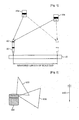
- FIG. 1 is a diagram showing the configuration of a prior art three-dimensional measurement system using an IGPS.
- the three-dimensional measurement system using an IGPS includes a scale bar 10, a vector bar 20, a plurality of optical transmitters 30a and 30b, and a receiver 40.
- the receiver 40 is attached to the vector bar 20, and one end of the vector bar 20 is sharp to come into contact with the scale bar 10 in vertical during measurement.
- the receiver 40 receives electric waves and laser beams radiated from at least two optical transmitters 30a and 30b. At this time, the measurement is performed by moving the receiver 40 between two known positions. In the three-dimensional measurement system, measured coordinates of the positions are converted into a distance between the two positions, to thereby measure the distance between the two positions.
- the invention has been made in order to solve the above-described problems. It is an object of the invention to provide a system and method that acquire an accurate distance between two positions by eliminating an error in a distance measurement between two positions.
- three-dimensional measurement system for acquiring a distance between two positions using an indoor global positioning system, including: the IGPS including a plurality of optical transmitters that radiate fan beams and further including a receiver that detects the radiated fan beams, wherein the IGPS is configured to detect a position of the receiver as a three-dimensional coordinate using the optical transmitters; a rescale bar having linear scales thereon; a linear encoder for measuring an absolute length between two points where the linear encoder moves on the rescale bar; and, a vector bar provided with the receiver and having one end attached to the linear encoder, the vector bar acquiring coordinates of the two points between which the vector bar moves by using the receiver, and measuring a relative length from the acquired coordinates.
- a ratio between the absolute length and the relative length is applied in rescaling an actual distance between two positions measured by the vector bar to thereby obtain an accurate actual distance between the two positions.
- a method for acquiring a distance between two positions using an indoor global positioning system may include: radiating fan beams using a plurality of optical transmitters of the IGPS; detecting the radiated fan beams using a receiver of the IGPS, wherein the IGPS detects a position of the receiver as a three-dimensional coordinate using the optical transmitters; measuring using a linear encoder an absolute length between two points where the linear encoder moves on a rescale bar having linear scales thereon; acquiring using vector bar, provided with the receiver and having one end attached to the linear encoder, coordinates of the two points between which the vector bar moves by using the receiver, and measuring using the vector a relative length from the acquired coordinates; and applying a ratio between the absolute length and the relative length in rescaling an actual distance between two positions measured by the vector bar to thereby obtain an accurate actual distance between the two positions.
- the present method even if a measurement is repeatedly performed in respect to a point indicated by the vector bar on the rescale bar, the present method is more accurate in comparison with a prior art in which the worker directly indicates the point. Therefore, even if a distance between positions longer than a measured distance are measured, there is no case that an error is accumulated.
- FIG. 2 is a conceptual view illustrating a case where a receiver receives laser beams generated from optical transmitters used in the present invention.
- a GPS Global Position System
- a GPS Global Position System
- IGPS indoor global positioning system
- the IGPS can detect the position of a receiver as a three-dimensional coordinate using a transmitter serving as a GPS satellite and the receiver serving as a GPS receiver.
- an optical transmitter 100 radiates two rotating fan beams 120 and 130.
- the rotating fan beams 120 and 130 may be laser fan beams or other optical beams.
- a receiver 110 receives the fan beams 120 and 130 radiated from the optical transmitter 100 to obtain the relative position to the optical transmitter 100 or a three- dimensional coordinate thereof. At this time, since the fan beams 120 and 130 are offset each other at a predetermined angle, the altitude of the receiver 110, which receives the fan beams 120 and 130, can be measured.
- FIG. 3 is a diagram showing the configuration of a three-dimensional measurement system using an IGPS according to the invention.
- the inventive three-dimensional measurement system using an IGPS includes a rescale bar 200, a linear encoder 300, a vector bar 400, a plurality of optical transmitters 500a and 500b, and a receiver 600.
- the rescale bar 200 has linear scales thereon, through which a length between two points on the rescale bar 200 can be perceived.
- the linear encoder 300 can reciprocate on the rescale bar 200 in a direction in which the rescale bar 200 runs, such that an accurate length can be measured with good measurement accuracy. For example, the measurement accuracy of the linear encoder 300 is within 0.01 mm.
- the vector bar 400 can move together as the linear encoder 300 moves.
- optical transmitters 500a and 500b radiate laser fan beams. Although only two optical transmitters 500a and 500b are shown in FIG. 3 , it is substantially preferably to provide at least three optical transmitters.
- the receiver 600 which may include one or more, is attached to an upper end of the vector bar 400 to detect the laser fan beams radiated from the optical transmitters 500a and 500b, thereby producing a three-dimensional coordinate corresponding to a current position thereof.
- the receiver 600 produces three- dimensional coordinates corresponding to the respective points, and the vector bar 400 converts the three-dimensional coordinates into one-dimensional coordinates through its calculation, thereby obtaining a relative length between the two points where the vector moves on the rescale bar 200.
- FIG. 4 is a flowchart illustrating a rescale method in a three-dimensional measurement system using an IGPS according to the invention. A rescale method using an IGPS will now be described with reference to FIG. 4 .
- three-dimensional coordinates of two positions to be measured are produce while moving a vector bar to the respective positions; and the three-dimensional coordinates are then converted into one-dimensional coordinates to calculate an actual distance between the two positions (S100).
- the linear encoder 300 moves from one point to another point on the rescale bar 200 to measure three-dimensional coordinates of the two points by the receiver 600 on the vector bar 400 which is fixed on the linear encoder 300 and is engaged therewith. Then, the measured three-dimensional coordinates are changed into a length value, to thereby obtain a relative length between the two points where the vector 400 moves on the rescale bar 200. Simultaneously, an absolute length between the two points where the linear encoder 600 moves on the rescale bar 200 is measured by the linear encoder 300 (S200).
- the calculated ratio is applied to rescale the actual distance between the two positions measured by the vector bar at S100, such that an accurate actual distance between the two positions can be obtained (S400).
- an error which may be generated in obtaining the actual distance between the two positions depends on the measurement accuracy of the linear encoder 300.
- a distance is measured by a ratio of 10% more than the actual distance between two positions.
- this ratio 10% is applied to the actual distance between the positions 'a' and 'b', that is, 2200 mm, and therefore, the actual distance can be rescaled to 2000 mm.
Landscapes
- Physics & Mathematics (AREA)
- General Physics & Mathematics (AREA)
- Engineering & Computer Science (AREA)
- Radar, Positioning & Navigation (AREA)
- Remote Sensing (AREA)
- Electromagnetism (AREA)
- Computer Networks & Wireless Communication (AREA)
- Length Measuring Devices By Optical Means (AREA)
- Length Measuring Devices With Unspecified Measuring Means (AREA)
- Position Fixing By Use Of Radio Waves (AREA)
Description
- The present invention relates to a three-dimensional measurement system using an IGPS (Indoor Global Positioning System), and more particularly, to a system and a method that acquire an accurate distance measurement by eliminating an error in distance measurement between two positions.
-
FIG. 1 is a diagram showing the configuration of a prior art three-dimensional measurement system using an IGPS. Referring toFIG. 1 , the three-dimensional measurement system using an IGPS includes ascale bar 10, avector bar 20, a plurality ofoptical transmitters receiver 40. - The
receiver 40 is attached to thevector bar 20, and one end of thevector bar 20 is sharp to come into contact with thescale bar 10 in vertical during measurement. Thereceiver 40 receives electric waves and laser beams radiated from at least twooptical transmitters receiver 40 between two known positions. In the three-dimensional measurement system, measured coordinates of the positions are converted into a distance between the two positions, to thereby measure the distance between the two positions. - In the above-described three-dimensional measurement system using an IGPS, when the
vector bar 20 indicates a point on thescale bar 10, a worker needs to use his/ her hands to directly indicate the point. However, it is difficult for the worker to accurately indicate the point. Accordingly, a measurement value of the point may vary each time the measurement is performed. In addition, an error due to this problem may cause a cumulative error, and thus, when a distance between two positions is measured, the distance may be measured to be larger than an actual distance. - The invention has been made in order to solve the above-described problems. It is an object of the invention to provide a system and method that acquire an accurate distance between two positions by eliminating an error in a distance measurement between two positions.
- According to an aspect of the invention, there is provided three-dimensional measurement system for acquiring a distance between two positions using an indoor global positioning system, including: the IGPS including a plurality of optical transmitters that radiate fan beams and further including a receiver that detects the radiated fan beams, wherein the IGPS is configured to detect a position of the receiver as a three-dimensional coordinate using the optical transmitters; a rescale bar having linear scales thereon; a linear encoder for measuring an absolute length between two points where the linear encoder moves on the rescale bar; and, a vector bar provided with the receiver and having one end attached to the linear encoder, the vector bar acquiring coordinates of the two points between which the vector bar moves by using the receiver, and measuring a relative length from the acquired coordinates. A ratio between the absolute length and the relative length is applied in rescaling an actual distance between two positions measured by the vector bar to thereby obtain an accurate actual distance between the two positions.
- According to another aspect of the invention, there is provided a method for acquiring a distance between two positions using an indoor global positioning system. The method may include: radiating fan beams using a plurality of optical transmitters of the IGPS; detecting the radiated fan beams using a receiver of the IGPS, wherein the IGPS detects a position of the receiver as a three-dimensional coordinate using the optical transmitters; measuring using a linear encoder an absolute length between two points where the linear encoder moves on a rescale bar having linear scales thereon; acquiring using vector bar, provided with the receiver and having one end attached to the linear encoder, coordinates of the two points between which the vector bar moves by using the receiver, and measuring using the vector a relative length from the acquired coordinates; and applying a ratio between the absolute length and the relative length in rescaling an actual distance between two positions measured by the vector bar to thereby obtain an accurate actual distance between the two positions.
- According to the present invention, even if a measurement is repeatedly performed in respect to a point indicated by the vector bar on the rescale bar, the present method is more accurate in comparison with a prior art in which the worker directly indicates the point. Therefore, even if a distance between positions longer than a measured distance are measured, there is no case that an error is accumulated.
-
-
FIG. 1 is a diagram showing the configuration of a prior art three-dimensional measurement system using an IGPS; -
FIG. 2 is a conceptual view illustrating a case where a receiver receives laser beams generated from optical transmitters according to the invention; -
FIG. 3 is a diagram showing the configuration of a three-dimensional measurement system using an IGPS according to the invention; and -
FIG. 4 is a flowchart illustrating a rescale method performed in a three-dimensional measurement system using an IGPS according to the invention. - The invention will now be described in detail with reference to the accompanying drawings.
-
FIG. 2 is a conceptual view illustrating a case where a receiver receives laser beams generated from optical transmitters used in the present invention. - In general, a GPS (Global Position System) recognizes and determines a three- dimensional coordinate corresponding to the position of a GPS receiver using three or more GPS satellites. This concept can also be applied in the indoor, which is representative of an indoor global positioning system (IGPS). The IGPS can detect the position of a receiver as a three-dimensional coordinate using a transmitter serving as a GPS satellite and the receiver serving as a GPS receiver.
- Referring to
FIG. 2 , anoptical transmitter 100 radiates two rotatingfan beams fan beams receiver 110 receives thefan beams optical transmitter 100 to obtain the relative position to theoptical transmitter 100 or a three- dimensional coordinate thereof. At this time, since thefan beams receiver 110, which receives thefan beams -
FIG. 3 is a diagram showing the configuration of a three-dimensional measurement system using an IGPS according to the invention. Referring toFIG. 3 , the inventive three-dimensional measurement system using an IGPS includes arescale bar 200, alinear encoder 300, avector bar 400, a plurality ofoptical transmitters receiver 600. - The
rescale bar 200 has linear scales thereon, through which a length between two points on therescale bar 200 can be perceived. Thelinear encoder 300 can reciprocate on therescale bar 200 in a direction in which therescale bar 200 runs, such that an accurate length can be measured with good measurement accuracy. For example, the measurement accuracy of thelinear encoder 300 is within 0.01 mm. In addition, since a lower end of thevector bar 400 is fixed on thelinear encoder 300, thevector bar 400 can move together as thelinear encoder 300 moves. - Further, the
optical transmitters optical transmitters FIG. 3 , it is substantially preferably to provide at least three optical transmitters. - The
receiver 600, which may include one or more, is attached to an upper end of thevector bar 400 to detect the laser fan beams radiated from theoptical transmitters vector bar 400 moves from one point to another point on therescale bar 200, thereceiver 600 produces three- dimensional coordinates corresponding to the respective points, and thevector bar 400 converts the three-dimensional coordinates into one-dimensional coordinates through its calculation, thereby obtaining a relative length between the two points where the vector moves on therescale bar 200. Simultaneously, it is also possible to obtain an absolute length between the two points where thelinear encoder 300 being engaged with thevector bar 400 moves on therescale bar 200. Then, an actual distance between the two positions can be accurately obtained by rescaling the actual distance using the ratio between the relative length and the absolute length. -
FIG. 4 is a flowchart illustrating a rescale method in a three-dimensional measurement system using an IGPS according to the invention. A rescale method using an IGPS will now be described with reference toFIG. 4 . - First, three-dimensional coordinates of two positions to be measured are produce while moving a vector bar to the respective positions; and the three-dimensional coordinates are then converted into one-dimensional coordinates to calculate an actual distance between the two positions (S100).
- Subsequently, the
linear encoder 300 moves from one point to another point on therescale bar 200 to measure three-dimensional coordinates of the two points by thereceiver 600 on thevector bar 400 which is fixed on thelinear encoder 300 and is engaged therewith. Then, the measured three-dimensional coordinates are changed into a length value, to thereby obtain a relative length between the two points where thevector 400 moves on therescale bar 200. Simultaneously, an absolute length between the two points where thelinear encoder 600 moves on therescale bar 200 is measured by the linear encoder 300 (S200). - Next, a ratio between the relative length of the
rescale bar 200 measured by thevector bar 400 and the absolute length of therescale bar 200 measured by thelinear encoder 300 is calculated (S300). - The calculated ratio is applied to rescale the actual distance between the two positions measured by the vector bar at S100, such that an accurate actual distance between the two positions can be obtained (S400).
- Here, it is noted that an error which may be generated in obtaining the actual distance between the two positions depends on the measurement accuracy of the
linear encoder 300. - The rescale method using the IGPS will now be described in detail by way of the following example. In case where an actual distance between two positions 'a' and 'b' in a measurement space is measured, it is assumed that the actual distance between the positions 'a' and 'b' acquired by the vector bar is 2200 mm. A rescale process should be performed in advance using the rescale bar before being measured the actual distance between the positions 'a' and 'b'. This is to accurately adjust measurement scales in the measurement space, thereby setting a measurement basis. If the relative length acquired by moving the vector bar attached to the linear encoder on the rescale bar is 1000 mm, and the absolute length acquired by the linear encoder is 1100 mm, a measurement error amounts to 100 mm. Therefore, it can be regarded that a distance is measured by a ratio of 10% more than the actual distance between two positions. To compensate the measurement error using the rescale process, this
ratio 10% is applied to the actual distance between the positions 'a' and 'b', that is, 2200 mm, and therefore, the actual distance can be rescaled to 2000 mm. - Although the three-dimensional measurement system and the rescale method using an IGPS has been described in connection with the embodiment by way of the accompanying drawings, it should be noted that the embodiment is not limitative, but illustrative. It will be apparent to those skilled in the art that various modifications and changes can be made without departing from the scope of the claims.
Claims (2)
- A three-dimensional measurement system for acquiring a distance between two positions using an indoor global positioning system (IGPS), comprising:the IGPS including a plurality of optical transmitters (100, 500a, 500b) configured to radiate fan beams (120, 130) and further including a receiver (600) configured to detect the radiated fan beams (120, 130), wherein the IGPS is configured to detect a position of the receiver (600) as a three-dimensional coordinate using the optical transmitters (100, 500a, 500b); characterised by further comprisinga rescale bar (200) having linear scales thereon;a linear encoder (300) configured to measure an absolute length between two points where the linear encoder (300) moves on the rescale bar (200); anda vector bar (400) provided with the receiver (600) and having one end attached to the linear encoder (300), the vector bar (400) configured to acquire coordinates of the two points between which the vector bar (400) moves by using the receiver (600), and configured to measure a relative length from the acquired coordinates,wherein the three-dimensional measuring system is configured to apply a ratio between the absolute length and the relative length in rescaling an actual distance between two positions measured by the vector bar (400) to thereby obtain an accurate actual distance between the two positions.
- A method for acquiring a distance between two positions using an indoor global positioning system (IGPS), the method comprising:radiating fan beams (120, 130) using a plurality of optical transmitters (100, 500a, 500b) of the IGPS;detecting the radiated fan beams (120, 130) using a receiver (600) of the IGPS, wherein the IGPS detects a position of the receiver (600) as a three-dimensional coordinate using the optical transmitters (100, 500a, 500b); characterised by further comprising the steps ofmeasuring using a linear encoder (300) an absolute length between two points where the linear encoder (300) moves on a rescale bar (200) having linear scales thereon;acquiring using vector bar (400), provided with the receiver (600) and having one end attached to the linear encoder (300), coordinates of the two points between which the vector bar (400) moves by using the receiver (600), and measuring using the vector bar (400) a relative length from the acquired coordinates; andapplying a ratio between the absolute length and the relative length in rescaling an actual distance between two positions measured by the vector bar (400) to thereby obtain an accurate actual distance between the two positions.
Applications Claiming Priority (2)
| Application Number | Priority Date | Filing Date | Title |
|---|---|---|---|
| KR1020060093333A KR100750897B1 (en) | 2006-09-26 | 2006-09-26 | 3D Measurement System and Rescale Method Using Indoor Positioning System |
| PCT/KR2007/004659 WO2008038969A1 (en) | 2006-09-26 | 2007-09-21 | Three-dimensional measurement system and rescaling method using indoor gps |
Publications (3)
| Publication Number | Publication Date |
|---|---|
| EP2067004A1 EP2067004A1 (en) | 2009-06-10 |
| EP2067004A4 EP2067004A4 (en) | 2011-01-19 |
| EP2067004B1 true EP2067004B1 (en) | 2015-05-13 |
Family
ID=38615001
Family Applications (1)
| Application Number | Title | Priority Date | Filing Date |
|---|---|---|---|
| EP20070808426 Not-in-force EP2067004B1 (en) | 2006-09-26 | 2007-09-21 | Three-dimensional measurement system and rescaling method using indoor gps |
Country Status (7)
| Country | Link |
|---|---|
| US (1) | US7834983B2 (en) |
| EP (1) | EP2067004B1 (en) |
| JP (1) | JP5289317B2 (en) |
| KR (1) | KR100750897B1 (en) |
| CN (1) | CN101517358B (en) |
| ES (1) | ES2540262T3 (en) |
| WO (1) | WO2008038969A1 (en) |
Families Citing this family (17)
| Publication number | Priority date | Publication date | Assignee | Title |
|---|---|---|---|---|
| KR100896692B1 (en) | 2007-07-18 | 2009-05-14 | 삼성중공업 주식회사 | Bundling and Rescaling Device for Indo GPS Setup and Indo GPS Setup Method Using the Same |
| KR100915042B1 (en) * | 2007-09-12 | 2009-09-02 | 삼성중공업 주식회사 | Method for matching curved surface of workpiece |
| KR100907682B1 (en) | 2007-11-02 | 2009-07-14 | 삼성중공업 주식회사 | Curved Member Internal Point Measuring Jig |
| KR100920014B1 (en) | 2008-05-27 | 2009-10-05 | 삼성중공업 주식회사 | Setup Bar for 3D Measurement |
| KR100982300B1 (en) | 2008-06-23 | 2010-09-15 | 삼성중공업 주식회사 | Indoor Positioning System and Indoor Positioning Method Using a Portable Device |
| KR100924857B1 (en) | 2008-07-02 | 2009-11-02 | 삼성중공업 주식회사 | Jig for measuring common point of indoor positioning system |
| KR101005900B1 (en) | 2008-12-16 | 2011-01-06 | 대우조선해양 주식회사 | Mobile coordinate measuring device and measuring method using indoor positioning system |
| US8953670B1 (en) | 2013-10-25 | 2015-02-10 | Mitsubishi Electric Research Laboratories, Inc. | Digital power encoder for direct digital-RF transmitter |
| CN103616662A (en) * | 2013-11-07 | 2014-03-05 | 天津大学 | Transmitting base station capable of being reversely arranged at top for angle intersection measurement |
| KR101846831B1 (en) * | 2014-06-30 | 2018-04-09 | 후아웨이 테크놀러지 컴퍼니 리미티드 | Method and apparatus for indoor positioning |
| CN105783917B (en) * | 2014-12-18 | 2019-05-07 | 阿里巴巴集团控股有限公司 | Geomagnetic-based mobile terminal positioning method and device |
| CN105203995B (en) * | 2015-09-08 | 2019-03-26 | 北京控制工程研究所 | A kind of indoor GPS system accuracy checking method |
| US10849205B2 (en) | 2015-10-14 | 2020-11-24 | Current Lighting Solutions, Llc | Luminaire having a beacon and a directional antenna |
| US11531106B2 (en) | 2018-07-10 | 2022-12-20 | Robert C. Newton | Asset tracking system and method |
| JP2020020784A (en) * | 2018-07-20 | 2020-02-06 | Jfeスチール株式会社 | Method for measuring size of rectangle object |
| CN109211186B (en) * | 2018-09-13 | 2021-03-02 | 国网福建省电力有限公司 | A method of non-contact rapid determination of distance between two points in space |
| CN109345633B (en) * | 2018-09-19 | 2022-12-23 | 北京机械设备研究所 | Panoramic three-dimensional registration system and method for augmented reality assembly |
Family Cites Families (18)
| Publication number | Priority date | Publication date | Assignee | Title |
|---|---|---|---|---|
| US5247487A (en) * | 1991-06-17 | 1993-09-21 | Spatial Positioning Systems, Inc. | Spatial measurement recovery system |
| AT403066B (en) * | 1991-07-12 | 1997-11-25 | Plasser Bahnbaumasch Franz | METHOD FOR DETERMINING THE DEVIATIONS OF THE ACTUAL LOCATION OF A TRACK SECTION |
| EP0753816A1 (en) | 1995-07-07 | 1997-01-15 | Thomson Consumer Electronics, Inc. | A method and apparatus for storing sensitive information securely in a relatively insecure storage medium |
| JPH0933634A (en) * | 1995-07-24 | 1997-02-07 | Mitsui Constr Co Ltd | Gps measuring device |
| US5932119A (en) * | 1996-01-05 | 1999-08-03 | Lazare Kaplan International, Inc. | Laser marking system |
| KR970075838A (en) * | 1997-09-22 | 1997-12-10 | 피명국 | Portable map range finder |
| US6181423B1 (en) * | 1998-10-06 | 2001-01-30 | Jorge Uriarte | Linear encoder providing engagement by engraving |
| DE69929168T2 (en) * | 1998-10-13 | 2006-08-24 | Arc Second, Inc. | OPTICAL TRANSMITTER WITH ROTATING HEAD FOR POSITION MEASUREMENT SYSTEM |
| US6519029B1 (en) * | 1999-03-22 | 2003-02-11 | Arc Second, Inc. | Low cost transmitter with calibration means for use in position measurement systems |
| US6545751B2 (en) * | 2000-02-28 | 2003-04-08 | Arc Second, Inc. | Low cost 2D position measurement system and method |
| US6501543B2 (en) * | 2000-02-28 | 2002-12-31 | Arc Second, Inc. | Apparatus and method for determining position |
| KR200206975Y1 (en) * | 2000-05-06 | 2000-12-15 | 정용훈 | An indoor position finding apparatus |
| US6909516B1 (en) * | 2000-10-20 | 2005-06-21 | Xerox Corporation | Two dimensional surface motion sensing system using registration marks and linear array sensor |
| KR100501500B1 (en) * | 2001-12-12 | 2005-07-18 | 한영수 | Length guage dispatch tool |
| JP2003227735A (en) * | 2002-01-31 | 2003-08-15 | Olympus Optical Co Ltd | Optical encoder and its sensor head |
| JP2004069442A (en) * | 2002-08-06 | 2004-03-04 | Nippon Telegr & Teleph Corp <Ntt> | Landscape information acquisition device, landscape information acquisition method, landscape information acquisition program, and recording medium |
| JP3956856B2 (en) * | 2003-01-28 | 2007-08-08 | 松下電工株式会社 | Laser distance measuring device |
| EP1566658A1 (en) * | 2004-02-19 | 2005-08-24 | Leica Geosystems AG | Handheld apparatus for measuring distances |
-
2006
- 2006-09-26 KR KR1020060093333A patent/KR100750897B1/en not_active Expired - Fee Related
-
2007
- 2007-09-21 EP EP20070808426 patent/EP2067004B1/en not_active Not-in-force
- 2007-09-21 WO PCT/KR2007/004659 patent/WO2008038969A1/en not_active Ceased
- 2007-09-21 CN CN2007800358950A patent/CN101517358B/en not_active Expired - Fee Related
- 2007-09-21 ES ES07808426.6T patent/ES2540262T3/en active Active
- 2007-09-21 JP JP2009530266A patent/JP5289317B2/en active Active
- 2007-09-21 US US12/442,669 patent/US7834983B2/en active Active
Also Published As
| Publication number | Publication date |
|---|---|
| ES2540262T3 (en) | 2015-07-09 |
| WO2008038969A1 (en) | 2008-04-03 |
| JP2010505113A (en) | 2010-02-18 |
| EP2067004A4 (en) | 2011-01-19 |
| US7834983B2 (en) | 2010-11-16 |
| US20100020305A1 (en) | 2010-01-28 |
| KR100750897B1 (en) | 2007-08-22 |
| JP5289317B2 (en) | 2013-09-11 |
| CN101517358B (en) | 2011-01-26 |
| EP2067004A1 (en) | 2009-06-10 |
| CN101517358A (en) | 2009-08-26 |
Similar Documents
| Publication | Publication Date | Title |
|---|---|---|
| US7834983B2 (en) | Three-dimensional measurement system and rescaling method using indoor GPS | |
| CN102540141B (en) | System for positioning a tool in a work space | |
| KR100779510B1 (en) | Reconnaissance Robot and Reconnaissance Robot Operation Control System | |
| EP1881342B1 (en) | System and method for estimating airborne radar antenna pointing errors | |
| JPWO2018181974A1 (en) | Judgment device, judgment method, and program | |
| CN111801596A (en) | Method and apparatus for determining correction information for a vehicle antenna | |
| US7400969B2 (en) | Navigation system | |
| EP2999939B1 (en) | System and method for measuring the volume of a tank | |
| US8848052B2 (en) | Processing method using an electric tool | |
| EP3399327B1 (en) | Pose estimation using radio frequency identification (rfid) tags | |
| WO2002004891A1 (en) | Spatial positioning | |
| WO2020209144A1 (en) | Position estimating device, estimating device, control method, program, and storage medium | |
| KR20120051981A (en) | Method for measuring verticality of structure using gnss and system thereof | |
| JP2022174149A5 (en) | VEHICLE CONTROL DEVICE, VEHICLE CONTROL METHOD AND VEHICLE CONTROL PROGRAM | |
| KR100976965B1 (en) | Navigation device and posisitioning method thereof | |
| US20170307410A1 (en) | Method for operating an x-ray device | |
| CN107917693A (en) | One kind is based on anallatic inclination measuring device and measuring method | |
| KR100929924B1 (en) | Common coordinate generation method using indoor location tracking system | |
| US20090273512A1 (en) | Global coordinate creation method for precision measurement of hollow frame | |
| KR102036080B1 (en) | Portable positioning device and method for operating portable positioning device | |
| JP3584899B2 (en) | Registration correction device for target search system | |
| KR101205977B1 (en) | Movement measuring apparatus of structure and method of the same | |
| KR20120083706A (en) | Apparatus for measuring vertical deformation of structure under construction and apparatus for computing compensatoin value against column shortening of structure under construction | |
| JP7512080B2 (en) | Position measuring system and position measuring method | |
| JP4695778B2 (en) | Deviation measuring device and course maintenance supporting device |
Legal Events
| Date | Code | Title | Description |
|---|---|---|---|
| PUAI | Public reference made under article 153(3) epc to a published international application that has entered the european phase |
Free format text: ORIGINAL CODE: 0009012 |
|
| 17P | Request for examination filed |
Effective date: 20090316 |
|
| AK | Designated contracting states |
Kind code of ref document: A1 Designated state(s): ES FR IT |
|
| AX | Request for extension of the european patent |
Extension state: AL BA HR MK RS |
|
| RIN1 | Information on inventor provided before grant (corrected) |
Inventor name: KIM, JAE-HOON Inventor name: PARK, JIN-HYUNG Inventor name: KIM, SUNG-HAN Inventor name: SONG, SE-HWAN Inventor name: CHUNG, SEONG-YOUB Inventor name: PARK, YOUNG-JUN |
|
| A4 | Supplementary search report drawn up and despatched |
Effective date: 20101220 |
|
| RIC1 | Information provided on ipc code assigned before grant |
Ipc: G01C 3/00 20060101AFI20080422BHEP Ipc: G01S 1/70 20060101ALI20101214BHEP |
|
| DAX | Request for extension of the european patent (deleted) | ||
| 17Q | First examination report despatched |
Effective date: 20120924 |
|
| RIC1 | Information provided on ipc code assigned before grant |
Ipc: G01B 11/14 20060101ALI20141017BHEP Ipc: G01S 1/70 20060101ALI20141017BHEP Ipc: G01C 3/00 20060101AFI20141017BHEP |
|
| GRAP | Despatch of communication of intention to grant a patent |
Free format text: ORIGINAL CODE: EPIDOSNIGR1 |
|
| INTG | Intention to grant announced |
Effective date: 20141205 |
|
| GRAS | Grant fee paid |
Free format text: ORIGINAL CODE: EPIDOSNIGR3 |
|
| GRAA | (expected) grant |
Free format text: ORIGINAL CODE: 0009210 |
|
| AK | Designated contracting states |
Kind code of ref document: B1 Designated state(s): ES FR IT |
|
| REG | Reference to a national code |
Ref country code: ES Ref legal event code: FG2A Ref document number: 2540262 Country of ref document: ES Kind code of ref document: T3 Effective date: 20150709 |
|
| REG | Reference to a national code |
Ref country code: FR Ref legal event code: PLFP Year of fee payment: 9 |
|
| PLBE | No opposition filed within time limit |
Free format text: ORIGINAL CODE: 0009261 |
|
| STAA | Information on the status of an ep patent application or granted ep patent |
Free format text: STATUS: NO OPPOSITION FILED WITHIN TIME LIMIT |
|
| 26N | No opposition filed |
Effective date: 20160216 |
|
| PG25 | Lapsed in a contracting state [announced via postgrant information from national office to epo] |
Ref country code: IT Free format text: LAPSE BECAUSE OF FAILURE TO SUBMIT A TRANSLATION OF THE DESCRIPTION OR TO PAY THE FEE WITHIN THE PRESCRIBED TIME-LIMIT Effective date: 20150513 |
|
| REG | Reference to a national code |
Ref country code: FR Ref legal event code: PLFP Year of fee payment: 10 |
|
| REG | Reference to a national code |
Ref country code: FR Ref legal event code: PLFP Year of fee payment: 11 |
|
| REG | Reference to a national code |
Ref country code: FR Ref legal event code: PLFP Year of fee payment: 12 |
|
| PGFP | Annual fee paid to national office [announced via postgrant information from national office to epo] |
Ref country code: FR Payment date: 20190820 Year of fee payment: 13 |
|
| PGFP | Annual fee paid to national office [announced via postgrant information from national office to epo] |
Ref country code: ES Payment date: 20191001 Year of fee payment: 13 |
|
| PG25 | Lapsed in a contracting state [announced via postgrant information from national office to epo] |
Ref country code: FR Free format text: LAPSE BECAUSE OF NON-PAYMENT OF DUE FEES Effective date: 20200930 |
|
| REG | Reference to a national code |
Ref country code: ES Ref legal event code: FD2A Effective date: 20220118 |
|
| PG25 | Lapsed in a contracting state [announced via postgrant information from national office to epo] |
Ref country code: ES Free format text: LAPSE BECAUSE OF NON-PAYMENT OF DUE FEES Effective date: 20200922 |