EP2066557B1 - Submarine escape suit assemblies - Google Patents
Submarine escape suit assemblies Download PDFInfo
- Publication number
- EP2066557B1 EP2066557B1 EP07804251A EP07804251A EP2066557B1 EP 2066557 B1 EP2066557 B1 EP 2066557B1 EP 07804251 A EP07804251 A EP 07804251A EP 07804251 A EP07804251 A EP 07804251A EP 2066557 B1 EP2066557 B1 EP 2066557B1
- Authority
- EP
- European Patent Office
- Prior art keywords
- liferaft
- outer casing
- assembly according
- suit
- casing
- Prior art date
- Legal status (The legal status is an assumption and is not a legal conclusion. Google has not performed a legal analysis and makes no representation as to the accuracy of the status listed.)
- Active
Links
Images




Classifications
-
- B—PERFORMING OPERATIONS; TRANSPORTING
- B63—SHIPS OR OTHER WATERBORNE VESSELS; RELATED EQUIPMENT
- B63C—LAUNCHING, HAULING-OUT, OR DRY-DOCKING OF VESSELS; LIFE-SAVING IN WATER; EQUIPMENT FOR DWELLING OR WORKING UNDER WATER; MEANS FOR SALVAGING OR SEARCHING FOR UNDERWATER OBJECTS
- B63C9/00—Life-saving in water
- B63C9/08—Life-buoys, e.g. rings; Life-belts, jackets, suits, or the like
- B63C9/087—Body suits, i.e. substantially covering the user's body ; Immersion suits, i.e. substantially completely covering the user
- B63C9/105—Body suits, i.e. substantially covering the user's body ; Immersion suits, i.e. substantially completely covering the user having gas-filled compartments
- B63C9/1055—Body suits, i.e. substantially covering the user's body ; Immersion suits, i.e. substantially completely covering the user having gas-filled compartments inflatable
-
- B—PERFORMING OPERATIONS; TRANSPORTING
- B63—SHIPS OR OTHER WATERBORNE VESSELS; RELATED EQUIPMENT
- B63C—LAUNCHING, HAULING-OUT, OR DRY-DOCKING OF VESSELS; LIFE-SAVING IN WATER; EQUIPMENT FOR DWELLING OR WORKING UNDER WATER; MEANS FOR SALVAGING OR SEARCHING FOR UNDERWATER OBJECTS
- B63C9/00—Life-saving in water
- B63C9/06—Floatable closed containers with accommodation for one or more persons inside
- B63C9/065—Floatable closed containers with accommodation for one or more persons inside for one person
-
- B—PERFORMING OPERATIONS; TRANSPORTING
- B63—SHIPS OR OTHER WATERBORNE VESSELS; RELATED EQUIPMENT
- B63C—LAUNCHING, HAULING-OUT, OR DRY-DOCKING OF VESSELS; LIFE-SAVING IN WATER; EQUIPMENT FOR DWELLING OR WORKING UNDER WATER; MEANS FOR SALVAGING OR SEARCHING FOR UNDERWATER OBJECTS
- B63C9/00—Life-saving in water
- B63C9/08—Life-buoys, e.g. rings; Life-belts, jackets, suits, or the like
- B63C9/087—Body suits, i.e. substantially covering the user's body ; Immersion suits, i.e. substantially completely covering the user
-
- B—PERFORMING OPERATIONS; TRANSPORTING
- B63—SHIPS OR OTHER WATERBORNE VESSELS; RELATED EQUIPMENT
- B63G—OFFENSIVE OR DEFENSIVE ARRANGEMENTS ON VESSELS; MINE-LAYING; MINE-SWEEPING; SUBMARINES; AIRCRAFT CARRIERS
- B63G8/00—Underwater vessels, e.g. submarines; Equipment specially adapted therefor
- B63G8/40—Rescue equipment for personnel
-
- B—PERFORMING OPERATIONS; TRANSPORTING
- B63—SHIPS OR OTHER WATERBORNE VESSELS; RELATED EQUIPMENT
- B63G—OFFENSIVE OR DEFENSIVE ARRANGEMENTS ON VESSELS; MINE-LAYING; MINE-SWEEPING; SUBMARINES; AIRCRAFT CARRIERS
- B63G8/00—Underwater vessels, e.g. submarines; Equipment specially adapted therefor
- B63G8/40—Rescue equipment for personnel
- B63G2008/406—Submarine escape suits
Definitions
- the invention relates to submarine escape suit assemblies including a liferaft carried in a pack on a suit.
- a submarine escape suit assembly of this kind is disclosed in closest prior art EP-A-0444400 .
- the pack remains attached to the suit while inflation is initiated.
- the liferaft then bursts from the pack for subsequent inflation and deployment outside the pack. It is a problem that some wearers of such a suit feel uncomfortable with the liferaft inflating in this way.
- a submarine escape suit assembly comprising a submarine escape suit and a liferaft pack, the liferaft pack comprising an outer casing attached to the suit and an inner casing held within the outer casing and containing a deflated liferaft, the outer casing being openable to release the inner casing and to expose an actuation device, actuation of the device passing gas to the liferaft for subsequent inflation and boarding.
- a liferaft pack comprising an outer casing for attachment to a submarine escape suit and an inner casing held within the outer casing and containing a deflated liferaft, the outer casing being openable to release the inner casing and to expose an actuation device, actuation of the device passing gas to the liferaft for subsequent inflation and boarding.
- the submarine escape suit assembly comprises a submarine escape suit indicated generally at 10 and a liferaft pack indicated generally at 11.
- the submarine escape suit 10 is made from a waterproof flexible material such as a rubberised fabric or a plastic coated fabric.
- the suit has a body portion 12, arm portions 13 and leg and boot portions 14. These parts are conventional and will not be described in further detail.
- a hood 15 extends over the body portion and is provided with a zipped entry opening 16 and translucent panels 17.
- the hood 15 has two lateral connection lines 18 that allow a face panel 19 of the hood 15 to be pulled away from the remainder of the hood 15. This is described in more detail in our co-pending UK patent application no 0618632.4
- the liferaft pack 11 is seen in more detail in Figures 2 and 3 .
- the liferaft pack comprises an outer casing 20 and an inner casing 21.
- the outer casing 20 is formed by first and second casing parts 22a, 22b.
- Each of the first and second casing parts 22a, 22b has a generally rectangular surface surrounded by four upstanding walls.
- the first and second casing parts 22a, 22b are in register and the edges of two respective adjacent walls are permanently connected to form a hinge 24 (see Figure 2 ) between the first and second casing parts 22a, 22b.
- the edges remaining walls are interconnected by two rows of zipper teeth 23a, 23b.
- teeth 23a, 23b extend continuously around the join between the first and second casing parts 22a, 22b except along a short stretch (see Figure 3 ) of two of the sides of the first and second casing parts 22a, 22b opposite the hinge 24. At that point, the first casing part 22a is provided a pull flap 25.
- the outer casing 22 is connected to the suit via reasonable connections 26 such as buckles or VELCRO TM
- the outer casing can be removed from the suit 10 for maintenance by releasing the connectors 26.
- the inner casing 21 is connected to the suit by an elongate cord 27 that is arranged in a serpentine fashion within the outer casing 20 and passes through the outer casing 20 to connect to the suit 10 at one of the connections 26.
- the outer casing 20 may be made from a lightweight fabric material.
- the inner casing 21 is a hermetically sealed pack formed, for example, by a barrier foil.
- the inner casing 21 may be vacuum packed.
- the inner casing 21 contains a deflated liferaft 28 and an inflation system 29.
- the cord 27 extends through the inner casing 21 to connect to the liferaft 28.
- the inflation system 29 includes an actuating cord 30 that extends out of the inner casing 21 and is located in the outer casing 20.
- the inner casing 21 carries a relative humidity indicator 31 that is aligned with a translucent window 32 in the outer casing 20 so that the indicator 31 can be read through the outer casing 20.
- the window 32 may be replaced by a hole.
- the inner casing 21 also contains a desiccant pack 33. This maintains relative humidity within the inner casing 21 to below 40% to prevent deterioration/corrosion of the liferaft 28.
- the submarine escape suit assembly is for escaping from a submarine.
- the wearer enters the suit 10 by opening the entry opening 16 and climbing into the suit 10 inserting arms into the arm portion 13, legs and feet into leg and boot portions 14 and body into the body portion 12.
- This configuration is shown in Figure 1 where it will be seen that the liferaft pack 11 is located approximately at the waist of the wearer to the left hand side of the wearer.
- the wearer then enters an escape chamber of the submarine where the wearer connects the suit to an air supply system of the submarine via a connector (not shown).
- the chamber then fills with water and a hatch opens to allow the wearer to ascend to the surface breathing the air within the suit 10 supplied by the system.
- the wearer When the wearer reaches the surface, the wearer adopts the position shown in Figure 4 .
- the wearer In this first stage, the wearer is lying on his/her back with his/her head above water and the liferaft pack 11 exposed. If the wearer wishes to deploy the liferaft 28, the wearer grabs the pull flap 25 so separating the zipper teeth 23a, 23b and hinging the first casing part 22a about the hinge 24.
- This second stage is shown in Figure 5 .
- the inner casing 21 is then released from the outer casing 20 and floats on the surface.
- This third stage is shown in Figure 6 .
- the inner casing 21 remains attached to the suit 10 by the cord 27 and the actuating cord 30 is expose.
- the actuating cord 30 can then be pulled to operate the inflation system 29. Air is then supplied to the liferaft which bursts from the inner casing 21 for subsequent inflation and deployment of the liferaft.
- This final stage is shown in Figure 7 . In this position, the liferaft 28 can be boarded by the wearer.
- This arrangement allows the wearer to choose when the liferaft 28 is inflated.
- inflation commences with the inner casing 21 separated from the suit 10 and this is an advantage.
- connection cord 27 and the actuating cord 30 may be combined.
- the form of the suit 10 is optional; any suitable submarine escape suit could be used. While it is preferred to have the liferaft pack 11 in the position shown in Figure 1 ; it could situated at any other convenient location although the front of the suit is preferred because, if it is located elsewhere, the liferaft pack 11 may snag as the wearer leaves the escape chamber.
- the inner casing 21 is hermetically sealed and vacuum packed, this is not essential.
- the connection between the first and second outer casing, parts 22a, 22b is shown as being by two sets of zipper teeth 23a, 23b that release when a force in excess of a predetermined minimum force is applied, other forms of releasable fastening could be used.
- VELCRO TM could be used or a tear strip.
- the hinge 24 is not essential; the first and second outer casing parts 22a, 22b could be completely separable.
Landscapes
- Engineering & Computer Science (AREA)
- Mechanical Engineering (AREA)
- Ocean & Marine Engineering (AREA)
- Aviation & Aerospace Engineering (AREA)
- Professional, Industrial, Or Sporting Protective Garments (AREA)
- Laying Of Electric Cables Or Lines Outside (AREA)
- Optical Communication System (AREA)
- Electric Cable Installation (AREA)
- Respiratory Apparatuses And Protective Means (AREA)
- Curing Cements, Concrete, And Artificial Stone (AREA)
Abstract
Description
- The invention relates to submarine escape suit assemblies including a liferaft carried in a pack on a suit.
- A submarine escape suit assembly of this kind is disclosed in closest prior art
EP-A-0444400 . In that arrangement, the pack remains attached to the suit while inflation is initiated. The liferaft then bursts from the pack for subsequent inflation and deployment outside the pack. It is a problem that some wearers of such a suit feel uncomfortable with the liferaft inflating in this way. - According to a first aspect of the invention, there is provided a submarine escape suit assembly comprising a submarine escape suit and a liferaft pack, the liferaft pack comprising an outer casing attached to the suit and an inner casing held within the outer casing and containing a deflated liferaft, the outer casing being openable to release the inner casing and to expose an actuation device, actuation of the device passing gas to the liferaft for subsequent inflation and boarding.
- According to a second aspect of the invention, there is provided a liferaft pack comprising an outer casing for attachment to a submarine escape suit and an inner casing held within the outer casing and containing a deflated liferaft, the outer casing being openable to release the inner casing and to expose an actuation device, actuation of the device passing gas to the liferaft for subsequent inflation and boarding.
- The following is a more detailed description of an embodiment of the invention by way, of example, reference being made to the accompanying drawings in which:-
-
Figure 1 is a front elevation of a submarine escape suit assembly including a submarine escape suit and a liferaft pack, -
Figure 2 is a schematic side elevation, partly in section, of the liferaft pack ofFigure 1 , -
Figure 3 is a schematic end elevation, partly in section, of the liferaft pack ofFigures 1 and2 , -
Figure 4 is a view of a person wearing the submarine escape suit assembly ofFigures 1 ,2 and 3 on the surface of the sea and showing a first stage in the deployment of the liferaft, -
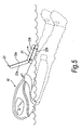
Figure 5 is a similar view toFigure 4 but showing a second stage in the deployment of a liferaft, -
Figure 6 is a similar view toFigures 4 and5 but showing a third stage in the deployment of the liferaft, -
Figure 7 is a similar view toFigures 4 and5 as showing the liferaft deployed, and, -
Figure 8 is a similar view toFigure 6 but showing an alternative method for deploying the liferaft. - Referring first to
Figure 1 , the submarine escape suit assembly comprises a submarine escape suit indicated generally at 10 and a liferaft pack indicated generally at 11. - The
submarine escape suit 10 is made from a waterproof flexible material such as a rubberised fabric or a plastic coated fabric. The suit has abody portion 12,arm portions 13 and leg and bootportions 14. These parts are conventional and will not be described in further detail. - A
hood 15 extends over the body portion and is provided with a zipped entry opening 16 andtranslucent panels 17. In addition, thehood 15 has twolateral connection lines 18 that allow aface panel 19 of thehood 15 to be pulled away from the remainder of thehood 15. This is described in more detail in our co-pendingUK patent application no 0618632.4 - The
liferaft pack 11 is seen in more detail inFigures 2 and 3 . The liferaft pack comprises anouter casing 20 and aninner casing 21. Theouter casing 20 is formed by first andsecond casing parts second casing parts second casing parts Figure 2 ) between the first andsecond casing parts zipper teeth teeth second casing parts Figure 3 ) of two of the sides of the first andsecond casing parts hinge 24. At that point, thefirst casing part 22a is provided apull flap 25. - The outer casing 22 is connected to the suit via
reasonable connections 26 such as buckles or VELCRO™ The outer casing can be removed from thesuit 10 for maintenance by releasing theconnectors 26. - The
inner casing 21 is connected to the suit by anelongate cord 27 that is arranged in a serpentine fashion within theouter casing 20 and passes through theouter casing 20 to connect to thesuit 10 at one of theconnections 26. The function of this will be described below. Theouter casing 20 may be made from a lightweight fabric material. - The
inner casing 21 is a hermetically sealed pack formed, for example, by a barrier foil. Theinner casing 21 may be vacuum packed. Theinner casing 21 contains a deflated liferaft 28 and aninflation system 29. Thecord 27 extends through theinner casing 21 to connect to the liferaft 28. Theinflation system 29 includes anactuating cord 30 that extends out of theinner casing 21 and is located in theouter casing 20. - The
inner casing 21 carries arelative humidity indicator 31 that is aligned with atranslucent window 32 in theouter casing 20 so that theindicator 31 can be read through theouter casing 20. Thewindow 32 may be replaced by a hole. Theinner casing 21 also contains adesiccant pack 33. This maintains relative humidity within theinner casing 21 to below 40% to prevent deterioration/corrosion of the liferaft 28. - In use, the submarine escape suit assembly is for escaping from a submarine. The wearer enters the
suit 10 by opening the entry opening 16 and climbing into thesuit 10 inserting arms into thearm portion 13, legs and feet into leg and bootportions 14 and body into thebody portion 12. This configuration is shown inFigure 1 where it will be seen that theliferaft pack 11 is located approximately at the waist of the wearer to the left hand side of the wearer. - The wearer then enters an escape chamber of the submarine where the wearer connects the suit to an air supply system of the submarine via a connector (not shown). The chamber then fills with water and a hatch opens to allow the wearer to ascend to the surface breathing the air within the
suit 10 supplied by the system. - When the wearer reaches the surface, the wearer adopts the position shown in
Figure 4 . In this first stage, the wearer is lying on his/her back with his/her head above water and theliferaft pack 11 exposed. If the wearer wishes to deploy the liferaft 28, the wearer grabs thepull flap 25 so separating thezipper teeth first casing part 22a about thehinge 24. This second stage is shown inFigure 5 . - The
inner casing 21 is then released from theouter casing 20 and floats on the surface. This third stage is shown inFigure 6 . Theinner casing 21 remains attached to thesuit 10 by thecord 27 and the actuatingcord 30 is expose. The actuatingcord 30 can then be pulled to operate theinflation system 29. Air is then supplied to the liferaft which bursts from theinner casing 21 for subsequent inflation and deployment of the liferaft. This final stage is shown inFigure 7 . In this position, the liferaft 28 can be boarded by the wearer. - This arrangement allows the wearer to choose when the liferaft 28 is inflated. In addition, inflation commences with the
inner casing 21 separated from thesuit 10 and this is an advantage. - It is not necessary to use a
separate attachment cord 27 and actuatingcord 30. As seen inFigure 7 , theconnection cord 27 and the actuatingcord 30 may be combined. - It will be appreciated that there are a number of other alterations that can be made to the arrangement described above with reference to the drawings. The form of the
suit 10 is optional; any suitable submarine escape suit could be used. While it is preferred to have theliferaft pack 11 in the position shown inFigure 1 ; it could situated at any other convenient location although the front of the suit is preferred because, if it is located elsewhere, theliferaft pack 11 may snag as the wearer leaves the escape chamber. - Although it is preferred that the
inner casing 21 is hermetically sealed and vacuum packed, this is not essential. Although the connection between the first and second outer casing,parts zipper teeth - The
hinge 24 is not essential; the first and secondouter casing parts
Claims (16)
- A submarine escape suit assembly comprising a submarine escape suit (10) and a liferaft pack (11), characterized in that the liferaft pack (11) compres an outer casing (20) attached to the suit (10) and an inner casing (21) held within the outer casing (20) and containing a deflated liferaft (28), the outer casing (20) being openable to release the inner casing (21) and to expose an actuation device (30), actuation of the device (30) passing gas to the liferaft (28) for subsequent inflation and boarding.
- As assembly according to claim 1 wherein the outer casing (20) is formed by first and second parts (22a, 22b) connected by a releasable fastening (23a, 23b) to allow opening of the outer casing (20).
- An assembly according to claim 2 wherein the releasable fastening (23a, 23b) releases when a force in excess of a predetermined minimum force is applied to the first outer casing part (22a) to pull said part (22a) away from the second outer casing part (22b).
- An assembly according to claim 3 wherein the first and second outer casing parts (22a, 22b) are partially permanently interconnected to form a hinge (24) therebetween, the releasable fastening (23a, 23b) interconnecting all or substantially all of the remainders of the first and second outer casing parts (22a, 22b).
- An assembly according to any one of claims 2 to 4 wherein the releasable fastening comprises two sets of engaging zipper teeth (23a, 23b) that can be pulled apart.
- An assembly according to any one of claims 1 to 5 wherein the first outer casing part (22a) is formed with a handle (25) for pulling said first outer casing part (22a) away from said second outer casing part (22b) to open the outer casing (20).
- As assembly according to any one of claims 1 to 6 wherein the outer casing (20) is connected to the suit by releasable straps (26).
- An assembly according to any one of claims 1 to 7 wherein the liferaft (28) is connected to the suit by a cord (27), the cord (27) passing through the inner casing (21) and the outer casing (20).
- An assembly according to any one of claims 1 to 8 wherein the actuation device comprises a cord (30) connected to an inflation system (29) of the liferaft (28).
- An assembly according to claim 8 when dependent on claim 9 wherein the actuation cord (30) is the cord connecting the liferaft to the suit..
- An assembly according to any one of claims 1 to 10 wherein the inner casing (21) is hermetically sealed.
- An assembly according to any one of claims 1 to 11 wherein the liferaft (28) is vacuum packed in the inner casing (21).
- An assembly according to any one of claims 1 to 12 herein the inner casing (21) contains a packed deflated liferaft (28) and an inflation system (29) connected to said actuation device (30).
- An assembly according to any one of claims 1 to 13 wherein the inner casing (21) contains a relative humidity indicator (31) for indicating the relative humidity within the inner casing (21), the outer casing (20) having a window (32) through which the relative humidity indicator (31) can be viewed.
- A liferaft pack comprising an outer casing (20) for attachment to a submarine escape suit and an inner casing (21) held within the outer casing (20) and containing a deflated liferaft (28), the outer casing (20) being openable to release the inner casing (21) and to expose an actuation device (30), actuation of the device passing gas to the liferaft (28) for subsequent inflation and boarding.
- A method of deploying a liferaft (28) carried in an inner container (21) carried in an outer container (20) attached to a submarine escape suit (10) comprising opening the outer container (20), removing the inner container (21) and then inflating the liferaft (28) and deploying the liferaft (28).
Applications Claiming Priority (2)
| Application Number | Priority Date | Filing Date | Title |
|---|---|---|---|
| GB0618630A GB2441985A (en) | 2006-09-21 | 2006-09-21 | A submarine escape suit and liferaft pack assembly |
| PCT/GB2007/003457 WO2008035040A1 (en) | 2006-09-21 | 2007-09-11 | Submarine escape suit assemblies |
Publications (2)
| Publication Number | Publication Date |
|---|---|
| EP2066557A1 EP2066557A1 (en) | 2009-06-10 |
| EP2066557B1 true EP2066557B1 (en) | 2010-08-18 |
Family
ID=37421398
Family Applications (1)
| Application Number | Title | Priority Date | Filing Date |
|---|---|---|---|
| EP07804251A Active EP2066557B1 (en) | 2006-09-21 | 2007-09-11 | Submarine escape suit assemblies |
Country Status (7)
| Country | Link |
|---|---|
| US (1) | US8092267B2 (en) |
| EP (1) | EP2066557B1 (en) |
| AT (1) | ATE477999T1 (en) |
| DE (1) | DE602007008585D1 (en) |
| ES (1) | ES2350800T3 (en) |
| GB (1) | GB2441985A (en) |
| WO (1) | WO2008035040A1 (en) |
Families Citing this family (8)
| Publication number | Priority date | Publication date | Assignee | Title |
|---|---|---|---|---|
| GB2441986B (en) * | 2006-09-21 | 2011-08-17 | Survitec Group Ltd | Submarine escape suits |
| GB2441959B (en) * | 2006-09-21 | 2011-06-15 | Survitec Group Ltd | Submarine escape suits |
| AR074300A1 (en) * | 2009-11-06 | 2011-01-05 | Nunez Karina Beatriz | SALVAMENT SUIT FOR WATCHES |
| US20120270453A1 (en) * | 2011-04-25 | 2012-10-25 | Feng-Jung Chang | Fully shrouded self-rescue inflatable boat |
| US20210354796A1 (en) * | 2020-04-16 | 2021-11-18 | Regina L. Bridges | Riptide angel drowning prevention suit |
| US12552502B2 (en) | 2021-05-18 | 2026-02-17 | Mustang Survival Corp. | Self-righting underwater escape and surface survival suit system |
| GB2636445A (en) | 2023-12-15 | 2025-06-18 | Rfd Beaufort Ltd | Life-saving appliance attachment arrangement |
| GB2639872A (en) | 2024-03-26 | 2025-10-08 | Rfd Beaufort Ltd | Life-saving system |
Family Cites Families (6)
| Publication number | Priority date | Publication date | Assignee | Title |
|---|---|---|---|---|
| US2814382A (en) * | 1955-09-21 | 1957-11-26 | Frederic H Lassiter | Cellophane packaging and method |
| US3198163A (en) * | 1963-02-13 | 1965-08-03 | Cadillac Products | Indicator device |
| US4569082A (en) * | 1984-12-13 | 1986-02-04 | Ainsworth Kathryn L | Bag construction with inflatable bladder |
| GB2241678B (en) * | 1990-02-24 | 1993-10-13 | Btr Plc | Submarine escape assembly |
| WO1997032776A1 (en) | 1994-10-18 | 1997-09-12 | Morten Heldahl | Method and equipment for securing a person, for marine use |
| GB2330517A (en) * | 1997-10-27 | 1999-04-28 | Beaufort Air Sea Equipment Ltd | Submarine Escape Suit incorporating a Life Raft |
-
2006
- 2006-09-21 GB GB0618630A patent/GB2441985A/en not_active Withdrawn
-
2007
- 2007-09-11 EP EP07804251A patent/EP2066557B1/en active Active
- 2007-09-11 DE DE602007008585T patent/DE602007008585D1/en active Active
- 2007-09-11 US US12/442,373 patent/US8092267B2/en active Active
- 2007-09-11 ES ES07804251T patent/ES2350800T3/en active Active
- 2007-09-11 AT AT07804251T patent/ATE477999T1/en not_active IP Right Cessation
- 2007-09-11 WO PCT/GB2007/003457 patent/WO2008035040A1/en not_active Ceased
Also Published As
| Publication number | Publication date |
|---|---|
| EP2066557A1 (en) | 2009-06-10 |
| US8092267B2 (en) | 2012-01-10 |
| GB0618630D0 (en) | 2006-11-01 |
| ATE477999T1 (en) | 2010-09-15 |
| DE602007008585D1 (en) | 2010-09-30 |
| ES2350800T3 (en) | 2011-01-27 |
| WO2008035040A1 (en) | 2008-03-27 |
| GB2441985A (en) | 2008-03-26 |
| US20090301377A1 (en) | 2009-12-10 |
Similar Documents
| Publication | Publication Date | Title |
|---|---|---|
| US8092267B2 (en) | Submarine escape suit assemblies | |
| AU708671B2 (en) | Low profile flotation collar | |
| US4498882A (en) | Hybrid personal flotation device | |
| US20130212764A1 (en) | Maritime Ballistic Safety Carrier | |
| EP2066555B1 (en) | Submarine escape suits | |
| JP4247112B2 (en) | Levitation device with multiple chambers | |
| EP2021233B1 (en) | Submarine escape suit | |
| EP2066556B1 (en) | Submarine escape suits | |
| CN103007454A (en) | High-altitude escape capsule | |
| EP3691759A1 (en) | Airbag compartment enclosure assembly | |
| EP0444400B1 (en) | Submarine escape assembly | |
| KR20140007536A (en) | Life belt | |
| US11254403B2 (en) | Salvage suit for shipwrecks with high functionality and insulation | |
| US2761154A (en) | Life saving suit | |
| JP6419740B2 (en) | Pendant life preserver | |
| KR101022270B1 (en) | Inflight Whole Body Suit | |
| CN115335282A (en) | Life jacket for water environment | |
| WO2025202207A1 (en) | Life-saving system | |
| CN224055398U (en) | Trample-proof safety airbag | |
| CN207580125U (en) | The automatic inflating that a kind of human chest is worn prevents drowned device | |
| AU4472899A (en) | Personal floatation device | |
| GB2337963A (en) | Impermeable suit with inflatable buoyancy means | |
| WO2023247428A1 (en) | Protection garments | |
| AU2018226376A1 (en) | Water Safety Device | |
| CN1468777A (en) | Standby emergency life buoy with compressed air bag |
Legal Events
| Date | Code | Title | Description |
|---|---|---|---|
| PUAI | Public reference made under article 153(3) epc to a published international application that has entered the european phase |
Free format text: ORIGINAL CODE: 0009012 |
|
| 17P | Request for examination filed |
Effective date: 20090417 |
|
| AK | Designated contracting states |
Kind code of ref document: A1 Designated state(s): AT BE BG CH CY CZ DE DK EE ES FI FR GB GR HU IE IS IT LI LT LU LV MC MT NL PL PT RO SE SI SK TR |
|
| AX | Request for extension of the european patent |
Extension state: AL BA HR MK RS |
|
| GRAP | Despatch of communication of intention to grant a patent |
Free format text: ORIGINAL CODE: EPIDOSNIGR1 |
|
| GRAS | Grant fee paid |
Free format text: ORIGINAL CODE: EPIDOSNIGR3 |
|
| GRAA | (expected) grant |
Free format text: ORIGINAL CODE: 0009210 |
|
| AK | Designated contracting states |
Kind code of ref document: B1 Designated state(s): AT BE BG CH CY CZ DE DK EE ES FI FR GB GR HU IE IS IT LI LT LU LV MC MT NL PL PT RO SE SI SK TR |
|
| REG | Reference to a national code |
Ref country code: GB Ref legal event code: FG4D |
|
| REG | Reference to a national code |
Ref country code: CH Ref legal event code: EP |
|
| REG | Reference to a national code |
Ref country code: IE Ref legal event code: FG4D |
|
| REG | Reference to a national code |
Ref country code: NL Ref legal event code: T3 |
|
| REF | Corresponds to: |
Ref document number: 602007008585 Country of ref document: DE Date of ref document: 20100930 Kind code of ref document: P |
|
| REG | Reference to a national code |
Ref country code: SE Ref legal event code: TRGR |
|
| LTIE | Lt: invalidation of european patent or patent extension |
Effective date: 20100818 |
|
| REG | Reference to a national code |
Ref country code: ES Ref legal event code: FG2A Effective date: 20110117 |
|
| PG25 | Lapsed in a contracting state [announced via postgrant information from national office to epo] |
Ref country code: AT Free format text: LAPSE BECAUSE OF FAILURE TO SUBMIT A TRANSLATION OF THE DESCRIPTION OR TO PAY THE FEE WITHIN THE PRESCRIBED TIME-LIMIT Effective date: 20100818 Ref country code: FI Free format text: LAPSE BECAUSE OF FAILURE TO SUBMIT A TRANSLATION OF THE DESCRIPTION OR TO PAY THE FEE WITHIN THE PRESCRIBED TIME-LIMIT Effective date: 20100818 Ref country code: LT Free format text: LAPSE BECAUSE OF FAILURE TO SUBMIT A TRANSLATION OF THE DESCRIPTION OR TO PAY THE FEE WITHIN THE PRESCRIBED TIME-LIMIT Effective date: 20100818 |
|
| PG25 | Lapsed in a contracting state [announced via postgrant information from national office to epo] |
Ref country code: SI Free format text: LAPSE BECAUSE OF FAILURE TO SUBMIT A TRANSLATION OF THE DESCRIPTION OR TO PAY THE FEE WITHIN THE PRESCRIBED TIME-LIMIT Effective date: 20100818 Ref country code: CY Free format text: LAPSE BECAUSE OF FAILURE TO SUBMIT A TRANSLATION OF THE DESCRIPTION OR TO PAY THE FEE WITHIN THE PRESCRIBED TIME-LIMIT Effective date: 20100818 Ref country code: PT Free format text: LAPSE BECAUSE OF FAILURE TO SUBMIT A TRANSLATION OF THE DESCRIPTION OR TO PAY THE FEE WITHIN THE PRESCRIBED TIME-LIMIT Effective date: 20101220 Ref country code: PL Free format text: LAPSE BECAUSE OF FAILURE TO SUBMIT A TRANSLATION OF THE DESCRIPTION OR TO PAY THE FEE WITHIN THE PRESCRIBED TIME-LIMIT Effective date: 20100818 Ref country code: BG Free format text: LAPSE BECAUSE OF FAILURE TO SUBMIT A TRANSLATION OF THE DESCRIPTION OR TO PAY THE FEE WITHIN THE PRESCRIBED TIME-LIMIT Effective date: 20101118 Ref country code: IS Free format text: LAPSE BECAUSE OF FAILURE TO SUBMIT A TRANSLATION OF THE DESCRIPTION OR TO PAY THE FEE WITHIN THE PRESCRIBED TIME-LIMIT Effective date: 20101218 |
|
| PG25 | Lapsed in a contracting state [announced via postgrant information from national office to epo] |
Ref country code: BE Free format text: LAPSE BECAUSE OF FAILURE TO SUBMIT A TRANSLATION OF THE DESCRIPTION OR TO PAY THE FEE WITHIN THE PRESCRIBED TIME-LIMIT Effective date: 20100818 Ref country code: GR Free format text: LAPSE BECAUSE OF FAILURE TO SUBMIT A TRANSLATION OF THE DESCRIPTION OR TO PAY THE FEE WITHIN THE PRESCRIBED TIME-LIMIT Effective date: 20101119 Ref country code: LV Free format text: LAPSE BECAUSE OF FAILURE TO SUBMIT A TRANSLATION OF THE DESCRIPTION OR TO PAY THE FEE WITHIN THE PRESCRIBED TIME-LIMIT Effective date: 20100818 |
|
| PG25 | Lapsed in a contracting state [announced via postgrant information from national office to epo] |
Ref country code: DK Free format text: LAPSE BECAUSE OF FAILURE TO SUBMIT A TRANSLATION OF THE DESCRIPTION OR TO PAY THE FEE WITHIN THE PRESCRIBED TIME-LIMIT Effective date: 20100818 Ref country code: MC Free format text: LAPSE BECAUSE OF NON-PAYMENT OF DUE FEES Effective date: 20100930 |
|
| PG25 | Lapsed in a contracting state [announced via postgrant information from national office to epo] |
Ref country code: RO Free format text: LAPSE BECAUSE OF FAILURE TO SUBMIT A TRANSLATION OF THE DESCRIPTION OR TO PAY THE FEE WITHIN THE PRESCRIBED TIME-LIMIT Effective date: 20100818 Ref country code: EE Free format text: LAPSE BECAUSE OF FAILURE TO SUBMIT A TRANSLATION OF THE DESCRIPTION OR TO PAY THE FEE WITHIN THE PRESCRIBED TIME-LIMIT Effective date: 20100818 Ref country code: CZ Free format text: LAPSE BECAUSE OF FAILURE TO SUBMIT A TRANSLATION OF THE DESCRIPTION OR TO PAY THE FEE WITHIN THE PRESCRIBED TIME-LIMIT Effective date: 20100818 Ref country code: SK Free format text: LAPSE BECAUSE OF FAILURE TO SUBMIT A TRANSLATION OF THE DESCRIPTION OR TO PAY THE FEE WITHIN THE PRESCRIBED TIME-LIMIT Effective date: 20100818 |
|
| PLBE | No opposition filed within time limit |
Free format text: ORIGINAL CODE: 0009261 |
|
| STAA | Information on the status of an ep patent application or granted ep patent |
Free format text: STATUS: NO OPPOSITION FILED WITHIN TIME LIMIT |
|
| 26N | No opposition filed |
Effective date: 20110519 |
|
| PG25 | Lapsed in a contracting state [announced via postgrant information from national office to epo] |
Ref country code: IE Free format text: LAPSE BECAUSE OF NON-PAYMENT OF DUE FEES Effective date: 20100911 |
|
| REG | Reference to a national code |
Ref country code: DE Ref legal event code: R097 Ref document number: 602007008585 Country of ref document: DE Effective date: 20110519 |
|
| PG25 | Lapsed in a contracting state [announced via postgrant information from national office to epo] |
Ref country code: MT Free format text: LAPSE BECAUSE OF FAILURE TO SUBMIT A TRANSLATION OF THE DESCRIPTION OR TO PAY THE FEE WITHIN THE PRESCRIBED TIME-LIMIT Effective date: 20100818 |
|
| REG | Reference to a national code |
Ref country code: CH Ref legal event code: PL |
|
| PG25 | Lapsed in a contracting state [announced via postgrant information from national office to epo] |
Ref country code: CH Free format text: LAPSE BECAUSE OF NON-PAYMENT OF DUE FEES Effective date: 20110930 Ref country code: LI Free format text: LAPSE BECAUSE OF NON-PAYMENT OF DUE FEES Effective date: 20110930 |
|
| PG25 | Lapsed in a contracting state [announced via postgrant information from national office to epo] |
Ref country code: HU Free format text: LAPSE BECAUSE OF FAILURE TO SUBMIT A TRANSLATION OF THE DESCRIPTION OR TO PAY THE FEE WITHIN THE PRESCRIBED TIME-LIMIT Effective date: 20110219 Ref country code: LU Free format text: LAPSE BECAUSE OF NON-PAYMENT OF DUE FEES Effective date: 20100911 |
|
| PG25 | Lapsed in a contracting state [announced via postgrant information from national office to epo] |
Ref country code: TR Free format text: LAPSE BECAUSE OF FAILURE TO SUBMIT A TRANSLATION OF THE DESCRIPTION OR TO PAY THE FEE WITHIN THE PRESCRIBED TIME-LIMIT Effective date: 20100818 |
|
| PGFP | Annual fee paid to national office [announced via postgrant information from national office to epo] |
Ref country code: NL Payment date: 20130926 Year of fee payment: 7 |
|
| PG25 | Lapsed in a contracting state [announced via postgrant information from national office to epo] |
Ref country code: NL Free format text: LAPSE BECAUSE OF NON-PAYMENT OF DUE FEES Effective date: 20150401 |
|
| REG | Reference to a national code |
Ref country code: FR Ref legal event code: PLFP Year of fee payment: 10 |
|
| REG | Reference to a national code |
Ref country code: FR Ref legal event code: PLFP Year of fee payment: 11 |
|
| REG | Reference to a national code |
Ref country code: FR Ref legal event code: PLFP Year of fee payment: 12 |
|
| P01 | Opt-out of the competence of the unified patent court (upc) registered |
Effective date: 20230525 |
|
| REG | Reference to a national code |
Ref country code: GB Ref legal event code: 732E Free format text: REGISTERED BETWEEN 20240118 AND 20240124 |
|
| REG | Reference to a national code |
Ref country code: DE Ref legal event code: R081 Ref document number: 602007008585 Country of ref document: DE Owner name: RFD BEAUFORT LTD., GB Free format text: FORMER OWNER: SURVITEC GROUP LTD., BIRKENHEAD, MERSEYSIDE, GB |
|
| REG | Reference to a national code |
Ref country code: ES Ref legal event code: PC2A Owner name: RF BEAUFORT LIMITED Effective date: 20241210 |
|
| PGFP | Annual fee paid to national office [announced via postgrant information from national office to epo] |
Ref country code: DE Payment date: 20250929 Year of fee payment: 19 |
|
| PGFP | Annual fee paid to national office [announced via postgrant information from national office to epo] |
Ref country code: GB Payment date: 20250722 Year of fee payment: 19 |
|
| PGFP | Annual fee paid to national office [announced via postgrant information from national office to epo] |
Ref country code: FR Payment date: 20250925 Year of fee payment: 19 |
|
| PGFP | Annual fee paid to national office [announced via postgrant information from national office to epo] |
Ref country code: SE Payment date: 20250927 Year of fee payment: 19 |
|
| PGFP | Annual fee paid to national office [announced via postgrant information from national office to epo] |
Ref country code: IT Payment date: 20251021 Year of fee payment: 19 |
|
| PGFP | Annual fee paid to national office [announced via postgrant information from national office to epo] |
Ref country code: ES Payment date: 20251001 Year of fee payment: 19 |