EP2066154A2 - Ablative plasma gun apparatus and system - Google Patents
Ablative plasma gun apparatus and system Download PDFInfo
- Publication number
- EP2066154A2 EP2066154A2 EP08169577A EP08169577A EP2066154A2 EP 2066154 A2 EP2066154 A2 EP 2066154A2 EP 08169577 A EP08169577 A EP 08169577A EP 08169577 A EP08169577 A EP 08169577A EP 2066154 A2 EP2066154 A2 EP 2066154A2
- Authority
- EP
- European Patent Office
- Prior art keywords
- electrodes
- pair
- gun
- arc
- ablative
- Prior art date
- Legal status (The legal status is an assumption and is not a legal conclusion. Google has not performed a legal analysis and makes no representation as to the accuracy of the status listed.)
- Granted
Links
- 239000000463 material Substances 0.000 claims abstract description 38
- 230000015556 catabolic process Effects 0.000 claims description 32
- 230000004044 response Effects 0.000 claims description 25
- 230000001681 protective effect Effects 0.000 claims description 9
- 239000006096 absorbing agent Substances 0.000 claims description 8
- 238000004891 communication Methods 0.000 claims description 5
- 239000002131 composite material Substances 0.000 claims description 4
- 229920001169 thermoplastic Polymers 0.000 claims description 4
- 239000004416 thermosoftening plastic Substances 0.000 claims description 4
- 239000000203 mixture Substances 0.000 claims description 3
- 230000004913 activation Effects 0.000 claims description 2
- 239000003990 capacitor Substances 0.000 description 23
- 239000004020 conductor Substances 0.000 description 17
- 230000009977 dual effect Effects 0.000 description 10
- 230000000116 mitigating effect Effects 0.000 description 9
- 238000004804 winding Methods 0.000 description 9
- 238000010586 diagram Methods 0.000 description 7
- 238000010891 electric arc Methods 0.000 description 4
- 238000012360 testing method Methods 0.000 description 4
- 229930040373 Paraformaldehyde Natural products 0.000 description 3
- -1 Polytetrafluoroethylene Polymers 0.000 description 3
- 238000002679 ablation Methods 0.000 description 3
- 229920006324 polyoxymethylene Polymers 0.000 description 3
- 230000035939 shock Effects 0.000 description 3
- OKTJSMMVPCPJKN-UHFFFAOYSA-N Carbon Chemical compound [C] OKTJSMMVPCPJKN-UHFFFAOYSA-N 0.000 description 2
- 229920000642 polymer Polymers 0.000 description 2
- 239000004810 polytetrafluoroethylene Substances 0.000 description 2
- 229940058401 polytetrafluoroethylene Drugs 0.000 description 2
- 230000005855 radiation Effects 0.000 description 2
- 230000001960 triggered effect Effects 0.000 description 2
- WFKWXMTUELFFGS-UHFFFAOYSA-N tungsten Chemical compound [W] WFKWXMTUELFFGS-UHFFFAOYSA-N 0.000 description 2
- 229910052721 tungsten Inorganic materials 0.000 description 2
- 239000010937 tungsten Substances 0.000 description 2
- 239000004952 Polyamide Substances 0.000 description 1
- 229910000831 Steel Inorganic materials 0.000 description 1
- XLOMVQKBTHCTTD-UHFFFAOYSA-N Zinc monoxide Chemical compound [Zn]=O XLOMVQKBTHCTTD-UHFFFAOYSA-N 0.000 description 1
- 239000000956 alloy Substances 0.000 description 1
- 229910045601 alloy Inorganic materials 0.000 description 1
- 230000015572 biosynthetic process Effects 0.000 description 1
- 229910052799 carbon Inorganic materials 0.000 description 1
- 238000010276 construction Methods 0.000 description 1
- 239000002360 explosive Substances 0.000 description 1
- 230000002349 favourable effect Effects 0.000 description 1
- 229910002804 graphite Inorganic materials 0.000 description 1
- 239000010439 graphite Substances 0.000 description 1
- 238000004519 manufacturing process Methods 0.000 description 1
- 229910044991 metal oxide Inorganic materials 0.000 description 1
- 150000004706 metal oxides Chemical class 0.000 description 1
- 238000012986 modification Methods 0.000 description 1
- 230000004048 modification Effects 0.000 description 1
- 238000000465 moulding Methods 0.000 description 1
- 230000007935 neutral effect Effects 0.000 description 1
- 229920002647 polyamide Polymers 0.000 description 1
- 229920001343 polytetrafluoroethylene Polymers 0.000 description 1
- 230000009467 reduction Effects 0.000 description 1
- 239000003870 refractory metal Substances 0.000 description 1
- 238000000926 separation method Methods 0.000 description 1
- 230000007480 spreading Effects 0.000 description 1
- 239000010959 steel Substances 0.000 description 1
- 230000001052 transient effect Effects 0.000 description 1
Images


Classifications
-
- H—ELECTRICITY
- H05—ELECTRIC TECHNIQUES NOT OTHERWISE PROVIDED FOR
- H05H—PLASMA TECHNIQUE; PRODUCTION OF ACCELERATED ELECTRICALLY-CHARGED PARTICLES OR OF NEUTRONS; PRODUCTION OR ACCELERATION OF NEUTRAL MOLECULAR OR ATOMIC BEAMS
- H05H1/00—Generating plasma; Handling plasma
- H05H1/24—Generating plasma
- H05H1/52—Generating plasma using exploding wires or spark gaps
-
- H—ELECTRICITY
- H01—ELECTRIC ELEMENTS
- H01H—ELECTRIC SWITCHES; RELAYS; SELECTORS; EMERGENCY PROTECTIVE DEVICES
- H01H33/00—High-tension or heavy-current switches with arc-extinguishing or arc-preventing means
- H01H33/70—Switches with separate means for directing, obtaining, or increasing flow of arc-extinguishing fluid
- H01H33/76—Switches with separate means for directing, obtaining, or increasing flow of arc-extinguishing fluid wherein arc-extinguishing gas is evolved from stationary parts; Selection of material therefor
Definitions
- the present invention relates generally to plasma guns, and more particularly to ablative plasma guns.
- Electric arc devices are used in a variety of applications, including series capacitor protection, high power switches, acoustic generators, shock wave generators, pulsed plasma thrusters and arc mitigation devices.
- Such devices include two or more main electrodes separated by a gap of air or another gas. A bias voltage is applied to the main electrodes across the gap.
- a high current pulse source can provide the high current pulse to trigger a plasma gun to generate conductive ablative plasma vapors between the main electrodes.
- the high current pulse source can also be used in devices such as rail guns, spark gap switches, lighting ballasts, and series capacitor protection, for example.
- the high current pulse is typically greater than about 5,000 Amps (5 kA), such as to generate adequate plasma vapors, for example. Additionally, high voltage, greater than about 5,000 Volts (5kV), is utilized to overcome a breakdown voltage of air and initiate the high current pulse across pulse electrodes, such as plasma gun electrodes for example.
- Typical high current pulses may be known as lightning pulses that can be defined as having an 8 microsecond rise time and a 20 microsecond fall time. Circuits to generate such high current pulses commonly utilize costly high-energy capacitors that can have capacitive values in the millifarad range. While existing plasma guns are suitable for their intended purpose, there is a need in the art for a plasma gun arrangement that overcomes these drawbacks.
- An embodiment of the invention includes an ablative plasma gun subassembly.
- the subassembly includes a body, a first pair and a second pair of gun electrodes having distal ends disposed within an interior of the body, and ablative material disposed proximate the distal ends of at least one of the first pair of gun electrodes and the second pair of gun electrodes.
- a further embodiment of the invention includes an ablative plasma gun subassembly disposed within a main arc device.
- the main arc device includes two or more main electrodes, each electrode of which is connected to an electrically different portion of an electric circuit.
- the ablative plasma gun subassembly includes a body, a first pair and a second pair of gun electrodes having distal ends disposed within an interior of the body, and ablative material disposed proximate the distal ends of at least one of the first pair of gun electrodes and the second pair of gun electrodes.
- the ablative plasma gun injects an ablative plasma into a main gap between the two or more main electrodes, thereby triggering an arc between the two or more main electrodes.
- An embodiment of the invention provides a plasma gun having more than one pair of gun electrodes disposed proximate an ablative material to generate conductive ablative plasma vapors.
- FIG 1 depicts an embodiment of a plasma gun 20, such as a dual electrode plasma gun 20 that includes at least a first pair of conductors 25 and a second pair of conductors 30. Each pair of conductors 25, 30 is in power connection with a corresponding pulse trigger circuit 27, 32 and pair of gun electrodes 55, 60 (best seen with reference to Figure 2 ), as will be described further below.
- the plasma gun 20 includes a barrel 35 (also herein referred to as a "body”) and a cap 40 having an orifice 45. The cap 40 is disposed upon the barrel 35 proximate the gun electrodes (shown in Figure 3 ).
- the orifice 45 defines a divergent nozzle that diverges in a direction leading away from the pairs of gun electrodes 55, 60 and plasma gun 20 emits conductive ionic plasma vapors 50 out of the orifice 45 in a spreading pattern at supersonic speed.
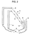
- Figure 2 depicts a schematic view of a first pair of gun electrodes 55 and a second pair of gun electrodes 60 disposed proximate each other within an interior of the barrel 35.
- reference numeral 65 shall refer to plasma gun 20 electrodes generally.
- the first pair and second pair of gun electrodes 55, 60 are in power connection with the pairs of conductors 25, 30, respectively.
- a plurality of arcs 70 are depicted disposed between the pairs of gun electrodes 55, 60.
- a first arc 75 is generated between the first pair of gun electrodes 55 and a second arc 80 is generated between the second pair of gun electrodes 60.
- Each of the first arc 75 and the second arc 80 may include more than one arc disposed between the pair of gun electrodes 65.
- Generation of the first arc 75 represents a high voltage, low current pulse that requires a voltage potential between the first pair of gun electrodes 55 that is directly related to the distance between the electrodes 65 of the first pair of electrodes 55.
- the voltage necessary to generate the first arc 75 must be greater than the breakdown voltage of air, which is about 30,000 volts per centimeter of distance or gap between the electrodes 65.
- an impedance between the first pair of gun electrodes 55 is significantly reduced.
- an impedance surrounding the first arc 75 such as between the second pair of gun electrodes 60, is also reduced.
- a voltage required to generate the second arc 80 which represents a low voltage, high current pulse is significantly reduced as compared to a breakdown voltage in the absence of the first arc 75.
- the high voltage, low current pulse is at least 5,000 volts with a current level less than about 5 amps and the low voltage, high current pulse is about 600 volts with a current level greater than 4,000 amps.
- FIG 3 depicts an enlarged exploded view of an embodiment of a plasma gun subassembly 83 proximate the cap 40.
- the subassembly 83 includes the barrel 35 and an ablative material 85.
- the interior of the barrel 35 defines an interior chamber 87 in which the electrodes 65 are disposed (better seen with reference to Figure 4 ).
- the ablative material 85 is disposed proximate the electrodes 65, particularly the second pair of electrodes 60 that generate the second arc 80 (best seen in Figure 2 ).
- the ablative material 85 is an ablative plug 86 that is separate from the cap 40 and the body 35 and may include keys 90 configured to fit within specific slots 95 of the barrel 35 to orient the ablative plug 86 such that it retains the electrodes 65.
- the ablative material 85 may be a discrete component, such as the ablative plug 86 disposed between the pairs of gun electrodes 55, 60 and the cap 40 as depicted in Figure 3 , or may alternatively be integrated or incorporated within at least one of the barrel 35 and the cap 40. Threads 100 may be disposed upon the barrel 35 to secure and retain the cap 40.
- Characteristics of the plasma vapors 50 may be controlled by dimensions and separation of the electrodes 65, dimensions of the interior chamber 87, proximity of electrodes 65 relative to the ablative material 85, the type of ablative material 85, a pulse shape and energy corresponding to the arcs 70, and the shape and size of the orifice 45.
- the ablative material 85 may be a thermoplastic, such as Polytetrafluoroethylene, Polyoxymethylene Polyamide, Poly-methyle-methacralate (PMMA), other ablative polymers, or various mixtures of these materials, including composites.
- Figure 4 depicts an enlarged section view of an embodiment of the plasma gun 20 proximate the cap 40.
- Electros 105, 110, 115, 120 each respectively having a distal end 125, 130, 135, 140, are disposed within the interior chamber 87, such that the cap 40 substantially encloses the distal ends 125-140 of the first and second pairs of gun electrodes 55, 60, the ablative material 85, and the interior chamber 87.
- the term "substantially encloses” considers enclosure by the cap 40 having the orifice 45.
- electrodes 110, 115 are the first pair of electrodes 55 and electrodes 105, 120 are the second pair of electrodes 60.
- the distal ends 130, 135 of the first pair of electrodes 110, 115 are separated and disposed opposite each other at opposite sides of the barrel 35 within the chamber 87.
- the distal ends 125, 140 of the second pair of electrodes 105, 120 are separated and disposed opposite each other at opposite sides of the barrel 35 within the chamber 87.
- the distal ends 130, 135 of the first pair of electrodes 110, 115 are separated by a first gap 142.
- a second gap 143 between the distal ends 125, 140 of the second pair of electrodes 105, 120 is equal to the first gap 142 between the first pair of electrodes 110, 115.
- each of the electrodes 105-120 is disposed such that no two electrodes 105-120 contact one another.
- the first and second gaps 142, 143 between pairs of electrodes 55, 60 is approximately 3 millimeters.
- the term "approximately" shall represent a deviation from the specified value that results from any of design, material, and assembly tolerances.
- the second pair of gun electrodes 60 are disposed proximate the first pair of gun electrodes 55 such that in response to generation of the first arc 75 across the first gap 142 between the first pair of gun electrodes 55, a breakdown voltage across the second gap 143 is significantly reduced as compared to the breakdown voltage in the absence of the first arc 75.
- a breakdown voltage of air between a second gap 143 having a dimension of 3 millimeters is approximately 9,000 volts.
- the breakdown voltage across the second gap 143 in response to generation of the first arc 75 across the first gap 142, is less than 2,700 volts, or reduced by 70 percent, to 30 percent of the breakdown voltage of air corresponding to the second gap 143 in the absence of the first arc 75. In another embodiment, in response to generation of the first arc 75, the breakdown voltage across the second gap 143 is less than 900 volts, or reduced by 90 percent, to 10 percent of the breakdown voltage of air corresponding to the second gap 143 in the absence of the first arc 75.
- generation of the first arc reduces the breakdown voltage across the second gap 143 by approximately 94 percent to less than 480 volts, or approximately 6 percent of the breakdown voltage of air corresponding to the second gap 143 in the absence of the first arc 75.
- the gun electrodes 65 may be formed as wires as shown to minimize expense, or they may have other forms.
- the material of the electrodes 65, or at least the distal ends 125-140 of the electrodes 65, may be tungsten steel, tungsten, other high temperature refractory metals / alloys, carbon / graphite, or other suitable arc electrode 65 materials.
- This can provide an incremental cost reduction in production in view of the relatively low cost and favorable molding properties of polymers such as poly-oxymethylene and poly-tetrafluoroethylene. Such construction and low cost can make the plasma gun 20 easily replaceable and disposable.
- Electrode lead pins 145, 150, 160, 165 may be provided for quick connection of the plasma gun 20 to a female connector (not shown), with appropriate locking and polarity keying.
- At least one of the first arc 75 and the second arc 80, proximate the ablative materials 85 of at least one of the plug 86, barrel 35, and cap 40, shall have an adequate current level to provide ablation of the ablative material 85 to generate the conductive ablative plasma vapors 50 (shown in Figure 1 ).
- Adequate current levels to initiate ablation of the ablative materials and generate the ablative plasma vapors 50 are typically greater than 5,000 amps (5kA). Accordingly, use of the dual electrode plasma gun 20 facilitates formation of the high current second arc 80 at voltages lower than the breakdown voltage of air between the gun electrodes 65. Radiation resulting from high current second arc 80 provides adequate ablation from the ablative material 85 to provide a high-energy plasma.
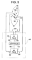
- FIG. 5 depicts a schematic diagram of one embodiment of a pulse generator (also herein referred to as "an electrical pulse circuit") 165 to generate the high-current pulse, such as may be suitable for use with the plasma gun 20 to generate the conductive plasma vapors 50, for example. While an embodiment of the pulse generator 165 has been described for use with the plasma gun 20, it will be appreciated that the scope of the invention is not so limited, and that the invention will also apply to pulse generators 165 used to develop the high current pulse in other applications, such as rail guns, spark gap switches, lighting ballasts, series capacitor protection circuits, and testing of lightening arrestor discs or Zinc Oxide (ZnO) nonlinear elements, for example.
- a pulse generator also herein referred to as "an electrical pulse circuit”
- the pulse generator 165 includes a high voltage electrical pulse source 170, a high current electrical pulse source 175, and a controller 180 to provide a trigger or enable signal 185, 190 to the pulse sources 170, 175.
- the high voltage pulse source 170 and high current pulse source 175 are in power connection, respectively, with a first pair of pulse electrodes 191 and a second pair of pulse electrodes 192, such as the first and second pairs of gun electrodes 55, 60 shown in Figure 2 for example.
- the high voltage pulse source 170 generates a voltage high enough to overcome the breakdown voltage of air corresponding to a first gap 196 defined between ends of the first pair of electrodes 191 and thereby generate a first arc 193 (also herein referred to as a "high voltage low current arc").
- the current of the first arc 193, such as the first arc 75 associated with the plasma gun 20 for example, may be less than that necessary to generate desired plasma vapors 50.
- Ionization associated with the first arc 193 significantly reduces impedance across and proximate the first gap 196.
- the first gap 196 is disposed proximate a second gap 197, defined between ends of the second pair of electrodes 192, such that an impedance across the second gap 197 is significantly reduced in response to generation of the first arc 193.
- the reduced impedance across the second gap 197, resulting from ionization in response to the first arc 193, allows creation of a second arc 194 (also herein referred to as a "low voltage high current arc") by the high current pulse source 175 with a voltage that is significantly less than the breakdown voltage of air corresponding to the second gap 197.
- a greater current level of the second arc 194, such as the second arc 80 for example, generates adequate radiation to produce the desired conductive plasma vapors 50 shown in Figure 1 .
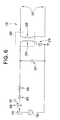
- FIG. 6 depicts one embodiment of the high voltage pulse source 170, such as a transformer pulse source 170.
- the transformer pulse source 170 includes a power source 195, a switch 200, a rectifier 202, and a transformer 205, such as a pulse transformer 205.
- the power source 195 is productive of a first voltage, such as 120 volts alternating current for example.
- the switch 200 is disposed in series with the power source 195 and in signal communication with the controller 180.
- the switch 200 is responsive to the controller 180 via the trigger signal 185 to close, thereby allowing current 210 to flow from the power source 195 through the switch 200, and a resistor 215 and capacitor 217 that define a resistive-capacitive charging constant.
- a charge from current 210 is stored within capacitor 217.
- a diode 218 short circuits or breaks down at the specific voltage, thereby allowing the charge stored within capacitor 217 to flow through a primary winding 220 of the transformer 205.
- Diode 218 provides what may be known as a "spark gap", such as may be used within high voltage ballasts, for example.
- resistor 215 is represented as a discrete resistor 215, it will be appreciated that the resistor 215 may be an equivalent resistance resulting from the primary winding 220 of the transformer 205, for example.
- a second voltage potential is established via a secondary winding 225 of the transformer 205 across a first pair of conductors 227, such as the first pair of conductors 25 of the plasma gun 20 for example.
- the second voltage potential across the first pair of conductors 227 is provided across the first pair of electrodes 191.
- the voltage potential between the first pair of conductors 227 is related to the first voltage potential and a turns ratio of the primary and secondary windings 220, 225.
- the second voltage potential between the first pair of conductors 227 is greater than 5,000 volts, with an arcing current of less than 5 amps.
- the voltage potential between the first pair of conductors 227 is greater than 10,000 volts with an arcing current of less than 1 amp.
- a duration of the current 210 is determined and controlled by controller 180 via the trigger signal 185 and switch 200. In one embodiment, the controller 180 closes the switch 200 for a duration equal to a desired duration of both the first arc 193 and the second arc 194.
- the high voltage pulse source 170 includes a pulse transformer, it will be appreciated that the scope of the invention is not so limited, and may apply to embodiments of the high voltage pulse source 170 that utilize other means to generate the voltage potential between the first pair of conductors 227, such as a capacitor discharge circuit, a lighting ballast circuit, and an ignition coil circuit, for example.
- FIG. 7 depicts one embodiment of the high current pulse source 175, such as a capacitor discharge pulse source 175.
- the capacitor discharge pulse source 175 includes a power source 230, a resistor 233, a rectifier 235, a charging switch 240, a charging circuit 245, and a discharge switch 260.
- An inductor 265 and a resistor 270 are connected in series with the discharge switch 260.
- the pulse source 175 may optionally include a transformer 275 to step-up the voltage of the power source 230, such as from 120 volts alternating current to 480 volts alternating current, for example.
- a metal oxide varistor 277 may be connected in parallel with a second pair of conductors 292 to protect the capacitor discharge pulse source 175 from excessive transient voltage, such as may be generated by the high voltage pulse source 170, for example.
- the charging circuit 245 includes a resistor 250 connected in series with a capacitor 255 that is connected in parallel across the second pair of conductors 292.
- the charging switch 240 is in power connection between the rectifier 235 and the charging circuit 245 and in signal communication with the controller 180.
- the discharge switch 260 is in power connection between the charging circuit 245 and the second pair of electrodes 192 via conductors 292.
- the switches 240, 260 are responsive to the trigger 190 to open and close, respectively.
- charging switch 240 Prior to receiving the trigger 190 signal, charging switch 240 is closed and discharge switch 260 is open.
- Current 280 from the power source 230 flows through resistor 233 and primary winding 285 of the transformer 275.
- a current and voltage are established via a secondary winding 290 of the transformer 275.
- the current and voltage established by the secondary winding 290 is converted to direct current via the rectifier 235.
- the direct current converted by the rectifier 235 flows through the switch 240 and resistor 250 and charges the capacitor 255.
- the charging switch 240 opens, thereby discontinuing charging of the charging circuit 245 from the power source 230. Additionally, the discharge switch 260 closes in response to the trigger 190, allowing the charge stored within the capacitor 255 to flow through the resistor 270 and inductor 265. The closing of the discharge switch 260 thereby establishes a voltage potential across the second pair of conductors 292, such as the second pair of conductors 30 associated with the plasma gun 20 for example. In an embodiment, the voltage potential across the second pair of conductors 292 provides a voltage potential across the second pair of electrodes 192 to generate the second arc 194 (shown in Figure 5 ).
- the high voltage pulse source 170 to initiate the first arc 193 thereby allows the high current pulse source 175 to generate the second arc 194 with an operating voltage that is less than the breakdown voltage of air across the gap 197 between the second pair of electrodes 192 that the second arc 194 crosses.
- the operating voltage of the high current pulse source 175 can be approximately 600 volts or less, which allows use of the capacitor 255 within the charging circuit 245 to have capacitance values within the microfarad range.
- Such capacitors 255 having capacitance values in the microfarad range are appreciated to be less costly than capacitors having capacitance values within the millifarad range.
- the capacitor 255 has a capacitance value less than 500 microfarads.
- the capacitor 255 has a capacitance value less than 250 microfarads.
- FIG 8 is a general schematic diagram of the dual electrode plasma gun 20 that may be used as a trigger in a main gap 300 of a main arc device 305.
- the term "main” is used to distinguish elements of a larger arc-based device from corresponding elements of the present plasma gun 20 (for example, used as a trigger), since the plasma gun 20 also constitutes an arc-based device.
- the main arc device 305 may be for example an arc mitigation device (also herein referred to as an "arc flash absorber”), a series capacitor protective bypass, a high power switch, an acoustic generator, a shock wave generator, a pulsed plasma thruster, or other arc devices.
- a main arc device 305 has two or more main electrodes 310, 315 separated by a gap 300 of air or another gas. Each electrode 310, 315 is connected to an electrically different portion 320, 325 of a circuit, such as different phases, neutral, or ground for example. This provides a bias voltage 330 across the arc gap 300.
- a trigger circuit such as the pulse generator 165, is in power communication with the plasma gun 20 and provides the high voltage (low current) and high current (low voltage) pulses to the plasma gun 20, causing it to inject ablative plasma vapors 150 into the main gap 300, lowering the gap 300 impedance to initiate a main arc 335 between the electrodes 310, 315.
- Figure 9 shows an example of a circuit used in testing an arc mitigation device 340.
- An arc flash 345 on the circuit 320, 325 is shown reducing the bias voltage 330 available across the gap 300.
- the impedance of the main electrode gap 300 may be designed for a given voltage by the size and spacing of the main electrodes 310, 315, so as not to allow arcing until triggering. Based upon characteristics of the conductive plasma vapors 150, the impedance of the main gap 300 can be designed to produce a relatively fast and robust main arc 335 in response to triggering of the plasma gun 20.
- Figures 10 and 11 depict the plasma gun 20 as may be configured in an exemplary embodiment to trigger an arc mitigation device 340 in a pressure-tolerant case 350.
- the trigger circuit 165 Upon receiving a trigger signal 355, the trigger circuit 165 sends the high voltage pulse and the high current pulse to the plasma gun 20, causing it to inject the ablative plasma 150 into the gap 300 between main electrodes 310, 315, 360 of the crowbar 340 to initiate a protective arc 335.
- the case 350 may be constructed to be tolerant of explosive pressure caused by the protective arc 335, and may include vents 365 for controlled pressure release.
- the arc mitigation device electrode gap 300 should be triggered as soon as an arc flash is detected on a protected circuit.
- One or more suitable sensors may be arranged to detect an arc flash and provide the trigger signal 355.
- the voltage across the gap 300 is normally less than 250 volts, which may not be enough to initiate the arc 335.
- the ablative plasma 150 bridges the gap 300 in less than about a millisecond to enable a protective short circuit via the arc 335 to extinguish the arc flash before damage is done.
- the crowbar electrodes 310, 315, 360 were spheres having diameters ranging from about 10mm to about 50mm, each spaced about 25mm from the adjacent sphere, with sphere centers located at a radius of about 37.52 mm from a common center point.
- the trigger was an ablative plasma gun 20 with ablative material 85 made of polyoxymethylene or polytetratluoroethylene.
- the cap 40 was located about 25mm below the plane of the electrode 310, 315, 360 sphere centers.
- Gap bias voltages ranging from about 120V to about 600V were triggered in testing by the dual electrode plasma gun 20 using a triggering pulse 8/20 (for example, a pulse with a rise time of about 8 microseconds and a fall time of about 20 microseconds) with the high voltage pulse of the first arc 75 having a voltage of about 10,000 volts (10kV) and current of less than 1 amp, and the high current pulse of the second arc 80 having a voltage of about 480 volts and current of about 5000 amps.
- a triggering pulse 8/20 for example, a pulse with a rise time of about 8 microseconds and a fall time of about 20 microseconds
- the high voltage pulse of the first arc 75 having a voltage of about 10,000 volts (10kV) and current of less than 1 amp
- the high current pulse of the second arc 80 having a voltage of about 480 volts and current of about 5000 amps.
- a conventional plasma gun absent the first and second pair of electrodes 55, 60 as described herein would require a trigger pulse having a voltage and current of about 20,000 volts and 5,000 amps for this same bias voltage, making the conventional plasma gun and its circuitry several times more expensive than the main electrodes.
- some embodiments of the invention may include some of the following advantages: a pulse generator capable of generating high current pulses having an overall lower cost; a pulse generator capable of generating high current pulses using lower cost high-energy microfarad range capacitors; and a plasma gun providing conductive ablative plasma vapors using a low cost dual source pulse generator.
Abstract
Description
- The present invention relates generally to plasma guns, and more particularly to ablative plasma guns.
- Electric arc devices are used in a variety of applications, including series capacitor protection, high power switches, acoustic generators, shock wave generators, pulsed plasma thrusters and arc mitigation devices. Such devices include two or more main electrodes separated by a gap of air or another gas. A bias voltage is applied to the main electrodes across the gap.
- One means to trigger such electric arc devices is via a high current pulse. For example, a high current pulse source can provide the high current pulse to trigger a plasma gun to generate conductive ablative plasma vapors between the main electrodes. The high current pulse source can also be used in devices such as rail guns, spark gap switches, lighting ballasts, and series capacitor protection, for example.
- The high current pulse is typically greater than about 5,000 Amps (5 kA), such as to generate adequate plasma vapors, for example. Additionally, high voltage, greater than about 5,000 Volts (5kV), is utilized to overcome a breakdown voltage of air and initiate the high current pulse across pulse electrodes, such as plasma gun electrodes for example. Typical high current pulses may be known as lightning pulses that can be defined as having an 8 microsecond rise time and a 20 microsecond fall time. Circuits to generate such high current pulses commonly utilize costly high-energy capacitors that can have capacitive values in the millifarad range. While existing plasma guns are suitable for their intended purpose, there is a need in the art for a plasma gun arrangement that overcomes these drawbacks.
- An embodiment of the invention includes an ablative plasma gun subassembly. The subassembly includes a body, a first pair and a second pair of gun electrodes having distal ends disposed within an interior of the body, and ablative material disposed proximate the distal ends of at least one of the first pair of gun electrodes and the second pair of gun electrodes.
- A further embodiment of the invention includes an ablative plasma gun subassembly disposed within a main arc device. The main arc device includes two or more main electrodes, each electrode of which is connected to an electrically different portion of an electric circuit. The ablative plasma gun subassembly includes a body, a first pair and a second pair of gun electrodes having distal ends disposed within an interior of the body, and ablative material disposed proximate the distal ends of at least one of the first pair of gun electrodes and the second pair of gun electrodes. In response to a low voltage high current arc between the second pair of gun electrodes, the ablative plasma gun injects an ablative plasma into a main gap between the two or more main electrodes, thereby triggering an arc between the two or more main electrodes.
- These and other advantages and features will be more readily understood from the following detailed description of preferred embodiments of the invention that is provided in connection with the accompanying drawings.
- Referring to the exemplary drawings wherein like elements are numbered alike in the accompanying Figures:
-
Figure 1 depicts a perspective view of a dual electrode plasma gun in accordance with an embodiment of the invention; -
Figure 2 depicts a schematic view of a first pair and a second pair of plasma gun electrodes in accordance with an embodiment of the invention; -
Figure 3 depicts an enlarged exploded perspective view of the dual electrode plasma gun ofFigure 1 in accordance with an embodiment of the invention; -
Figure 4 depicts an enlarged exploded partial cross section of a barrel of the dual electrode plasma gun ofFigure 3 in accordance with an embodiment of the invention; -
Figure 5 depicts a schematic diagram of an electrical pulse circuit in accordance with an embodiment of the invention; -
Figure 6 depicts a schematic diagram of a high voltage source of the electrical pulse circuit in accordance with an embodiment of the invention; -
Figure 7 depicts a schematic diagram of a high current source of the electrical pulse circuit in accordance with an embodiment of the invention; -
Figure 8 depicts a general circuit diagram of a dual electrode ablative plasma gun used to trigger an electric arc device in accordance with an embodiment of the invention; -
Figure 9 depicts an exemplary circuit diagram of a dual electrode ablative plasma gun trigger of an electric arc device in accordance with an embodiment of the invention; -
Figure 10 depicts a sectional view of an ablative plasma gun triggering an arc mitigation device in accordance with an embodiment of the invention; and -
Figure 11 depicts a perspective view of an ablative plasma gun triggering an arc mitigation device in accordance with an embodiment of the invention. - An embodiment of the invention provides a plasma gun having more than one pair of gun electrodes disposed proximate an ablative material to generate conductive ablative plasma vapors.
-
Figure 1 depicts an embodiment of aplasma gun 20, such as a dualelectrode plasma gun 20 that includes at least a first pair ofconductors 25 and a second pair ofconductors 30. Each pair ofconductors pulse trigger circuit gun electrodes 55, 60 (best seen with reference toFigure 2 ), as will be described further below. Theplasma gun 20 includes a barrel 35 (also herein referred to as a "body") and acap 40 having anorifice 45. Thecap 40 is disposed upon thebarrel 35 proximate the gun electrodes (shown inFigure 3 ). In an embodiment, theorifice 45 defines a divergent nozzle that diverges in a direction leading away from the pairs ofgun electrodes plasma gun 20 emits conductiveionic plasma vapors 50 out of theorifice 45 in a spreading pattern at supersonic speed. -
Figure 2 depicts a schematic view of a first pair ofgun electrodes 55 and a second pair ofgun electrodes 60 disposed proximate each other within an interior of thebarrel 35. As used hereinreference numeral 65 shall refer toplasma gun 20 electrodes generally. The first pair and second pair ofgun electrodes conductors arcs 70 are depicted disposed between the pairs ofgun electrodes first arc 75 is generated between the first pair ofgun electrodes 55 and asecond arc 80 is generated between the second pair ofgun electrodes 60. Each of thefirst arc 75 and thesecond arc 80 may include more than one arc disposed between the pair ofgun electrodes 65. - Generation of the
first arc 75 represents a high voltage, low current pulse that requires a voltage potential between the first pair ofgun electrodes 55 that is directly related to the distance between theelectrodes 65 of the first pair ofelectrodes 55. In one embodiment, the voltage necessary to generate thefirst arc 75 must be greater than the breakdown voltage of air, which is about 30,000 volts per centimeter of distance or gap between theelectrodes 65. In response to generation of thefirst arc 75 between the first pair ofgun electrodes 55, an impedance between the first pair ofgun electrodes 55 is significantly reduced. Furthermore, in response to generation of thefirst arc 75, an impedance surrounding thefirst arc 75, such as between the second pair ofgun electrodes 60, is also reduced. Accordingly, in response to generation of thefirst arc 75, a voltage required to generate thesecond arc 80, which represents a low voltage, high current pulse is significantly reduced as compared to a breakdown voltage in the absence of thefirst arc 75. For example, in an embodiment, the high voltage, low current pulse is at least 5,000 volts with a current level less than about 5 amps and the low voltage, high current pulse is about 600 volts with a current level greater than 4,000 amps. -
Figure 3 depicts an enlarged exploded view of an embodiment of a plasma gun subassembly 83 proximate thecap 40. Thesubassembly 83 includes thebarrel 35 and anablative material 85. The interior of thebarrel 35 defines aninterior chamber 87 in which theelectrodes 65 are disposed (better seen with reference toFigure 4 ). Theablative material 85 is disposed proximate theelectrodes 65, particularly the second pair ofelectrodes 60 that generate the second arc 80 (best seen inFigure 2 ). In one embodiment, theablative material 85 is anablative plug 86 that is separate from thecap 40 and thebody 35 and may includekeys 90 configured to fit withinspecific slots 95 of thebarrel 35 to orient theablative plug 86 such that it retains theelectrodes 65. Theablative material 85 may be a discrete component, such as theablative plug 86 disposed between the pairs ofgun electrodes cap 40 as depicted inFigure 3 , or may alternatively be integrated or incorporated within at least one of thebarrel 35 and thecap 40.Threads 100 may be disposed upon thebarrel 35 to secure and retain thecap 40. - Characteristics of the plasma vapors 50 (shown in
Figure 1 ) such as velocity, ion concentration, and spread, may be controlled by dimensions and separation of theelectrodes 65, dimensions of theinterior chamber 87, proximity ofelectrodes 65 relative to theablative material 85, the type ofablative material 85, a pulse shape and energy corresponding to thearcs 70, and the shape and size of theorifice 45. Theablative material 85 may be a thermoplastic, such as Polytetrafluoroethylene, Polyoxymethylene Polyamide, Poly-methyle-methacralate (PMMA), other ablative polymers, or various mixtures of these materials, including composites. -
Figure 4 depicts an enlarged section view of an embodiment of theplasma gun 20 proximate thecap 40. Fourelectrodes distal end interior chamber 87, such that thecap 40 substantially encloses the distal ends 125-140 of the first and second pairs ofgun electrodes ablative material 85, and theinterior chamber 87. As used herein, the term "substantially encloses" considers enclosure by thecap 40 having theorifice 45. In one exemplary embodiment,electrodes electrodes 55 andelectrodes electrodes 60. In an embodiment, the distal ends 130, 135 of the first pair ofelectrodes barrel 35 within thechamber 87. In another embodiment, the distal ends 125, 140 of the second pair ofelectrodes barrel 35 within thechamber 87. - As depicted, the distal ends 130, 135 of the first pair of
electrodes first gap 142. In one exemplary embodiment, asecond gap 143 between the distal ends 125, 140 of the second pair ofelectrodes first gap 142 between the first pair ofelectrodes second gaps electrodes - As described above, with reference to
Figure 2 , the second pair ofgun electrodes 60 are disposed proximate the first pair ofgun electrodes 55 such that in response to generation of thefirst arc 75 across thefirst gap 142 between the first pair ofgun electrodes 55, a breakdown voltage across thesecond gap 143 is significantly reduced as compared to the breakdown voltage in the absence of thefirst arc 75. For example, it will be appreciated that a breakdown voltage of air between asecond gap 143 having a dimension of 3 millimeters is approximately 9,000 volts. In one embodiment, in response to generation of thefirst arc 75 across thefirst gap 142, the breakdown voltage across thesecond gap 143 is less than 2,700 volts, or reduced by 70 percent, to 30 percent of the breakdown voltage of air corresponding to thesecond gap 143 in the absence of thefirst arc 75. In another embodiment, in response to generation of thefirst arc 75, the breakdown voltage across thesecond gap 143 is less than 900 volts, or reduced by 90 percent, to 10 percent of the breakdown voltage of air corresponding to thesecond gap 143 in the absence of thefirst arc 75. In yet another embodiment, generation of the first arc reduces the breakdown voltage across thesecond gap 143 by approximately 94 percent to less than 480 volts, or approximately 6 percent of the breakdown voltage of air corresponding to thesecond gap 143 in the absence of thefirst arc 75. - The
gun electrodes 65 may be formed as wires as shown to minimize expense, or they may have other forms. The material of theelectrodes 65, or at least the distal ends 125-140 of theelectrodes 65, may be tungsten steel, tungsten, other high temperature refractory metals / alloys, carbon / graphite, or othersuitable arc electrode 65 materials. - In one embodiment, at least a portion of the
barrel 35 of theplasma gun assembly 20 surrounding at least a portion of thegun electrodes 65 proximate the distal ends 125-140, is molded of theablative material 85. This can provide an incremental cost reduction in production in view of the relatively low cost and favorable molding properties of polymers such as poly-oxymethylene and poly-tetrafluoroethylene. Such construction and low cost can make theplasma gun 20 easily replaceable and disposable. Electrode lead pins 145, 150, 160, 165 may be provided for quick connection of theplasma gun 20 to a female connector (not shown), with appropriate locking and polarity keying. - With reference now to
Figures 2 and3 , at least one of thefirst arc 75 and thesecond arc 80, proximate theablative materials 85 of at least one of theplug 86,barrel 35, andcap 40, shall have an adequate current level to provide ablation of theablative material 85 to generate the conductive ablative plasma vapors 50 (shown inFigure 1 ). - Adequate current levels to initiate ablation of the ablative materials and generate the
ablative plasma vapors 50 are typically greater than 5,000 amps (5kA). Accordingly, use of the dualelectrode plasma gun 20 facilitates formation of the high currentsecond arc 80 at voltages lower than the breakdown voltage of air between thegun electrodes 65. Radiation resulting from high currentsecond arc 80 provides adequate ablation from theablative material 85 to provide a high-energy plasma. -
Figure 5 depicts a schematic diagram of one embodiment of a pulse generator (also herein referred to as "an electrical pulse circuit") 165 to generate the high-current pulse, such as may be suitable for use with theplasma gun 20 to generate theconductive plasma vapors 50, for example. While an embodiment of thepulse generator 165 has been described for use with theplasma gun 20, it will be appreciated that the scope of the invention is not so limited, and that the invention will also apply topulse generators 165 used to develop the high current pulse in other applications, such as rail guns, spark gap switches, lighting ballasts, series capacitor protection circuits, and testing of lightening arrestor discs or Zinc Oxide (ZnO) nonlinear elements, for example. - The
pulse generator 165 includes a high voltageelectrical pulse source 170, a high currentelectrical pulse source 175, and acontroller 180 to provide a trigger or enablesignal pulse sources voltage pulse source 170 and highcurrent pulse source 175 are in power connection, respectively, with a first pair ofpulse electrodes 191 and a second pair ofpulse electrodes 192, such as the first and second pairs ofgun electrodes Figure 2 for example. The highvoltage pulse source 170 generates a voltage high enough to overcome the breakdown voltage of air corresponding to afirst gap 196 defined between ends of the first pair ofelectrodes 191 and thereby generate a first arc 193 (also herein referred to as a "high voltage low current arc"). In an embodiment, the current of thefirst arc 193, such as thefirst arc 75 associated with theplasma gun 20 for example, may be less than that necessary to generate desiredplasma vapors 50. - Ionization associated with the
first arc 193 significantly reduces impedance across and proximate thefirst gap 196. Thefirst gap 196 is disposed proximate asecond gap 197, defined between ends of the second pair ofelectrodes 192, such that an impedance across thesecond gap 197 is significantly reduced in response to generation of thefirst arc 193. - The reduced impedance across the
second gap 197, resulting from ionization in response to thefirst arc 193, allows creation of a second arc 194 (also herein referred to as a "low voltage high current arc") by the highcurrent pulse source 175 with a voltage that is significantly less than the breakdown voltage of air corresponding to thesecond gap 197. A greater current level of thesecond arc 194, such as thesecond arc 80 for example, generates adequate radiation to produce the desiredconductive plasma vapors 50 shown inFigure 1 . -
Figure 6 depicts one embodiment of the highvoltage pulse source 170, such as atransformer pulse source 170. Thetransformer pulse source 170 includes apower source 195, aswitch 200, arectifier 202, and atransformer 205, such as apulse transformer 205. In an exemplary embodiment, thepower source 195 is productive of a first voltage, such as 120 volts alternating current for example. Theswitch 200 is disposed in series with thepower source 195 and in signal communication with thecontroller 180. Theswitch 200 is responsive to thecontroller 180 via thetrigger signal 185 to close, thereby allowing current 210 to flow from thepower source 195 through theswitch 200, and aresistor 215 andcapacitor 217 that define a resistive-capacitive charging constant. A charge from current 210 is stored withincapacitor 217. In response to thecapacitor 217 charging to a specific voltage, adiode 218 short circuits or breaks down at the specific voltage, thereby allowing the charge stored withincapacitor 217 to flow through a primary winding 220 of thetransformer 205.Diode 218 provides what may be known as a "spark gap", such as may be used within high voltage ballasts, for example. Althoughresistor 215 is represented as adiscrete resistor 215, it will be appreciated that theresistor 215 may be an equivalent resistance resulting from the primary winding 220 of thetransformer 205, for example. In response to the current 210 through the primary winding 220, a second voltage potential is established via a secondary winding 225 of thetransformer 205 across a first pair ofconductors 227, such as the first pair ofconductors 25 of theplasma gun 20 for example. In an embodiment, the second voltage potential across the first pair ofconductors 227 is provided across the first pair ofelectrodes 191. The voltage potential between the first pair ofconductors 227 is related to the first voltage potential and a turns ratio of the primary andsecondary windings conductors 227 is greater than 5,000 volts, with an arcing current of less than 5 amps. In another embodiment, the voltage potential between the first pair ofconductors 227 is greater than 10,000 volts with an arcing current of less than 1 amp. A duration of the current 210 is determined and controlled bycontroller 180 via thetrigger signal 185 andswitch 200. In one embodiment, thecontroller 180 closes theswitch 200 for a duration equal to a desired duration of both thefirst arc 193 and thesecond arc 194. - While an embodiment of the high
voltage pulse source 170 has been depicted including a pulse transformer, it will be appreciated that the scope of the invention is not so limited, and may apply to embodiments of the highvoltage pulse source 170 that utilize other means to generate the voltage potential between the first pair ofconductors 227, such as a capacitor discharge circuit, a lighting ballast circuit, and an ignition coil circuit, for example. -
Figure 7 depicts one embodiment of the highcurrent pulse source 175, such as a capacitordischarge pulse source 175. The capacitordischarge pulse source 175 includes apower source 230, aresistor 233, arectifier 235, a chargingswitch 240, a chargingcircuit 245, and adischarge switch 260. Aninductor 265 and aresistor 270 are connected in series with thedischarge switch 260. Thepulse source 175 may optionally include atransformer 275 to step-up the voltage of thepower source 230, such as from 120 volts alternating current to 480 volts alternating current, for example. Optionally, ametal oxide varistor 277 may be connected in parallel with a second pair ofconductors 292 to protect the capacitordischarge pulse source 175 from excessive transient voltage, such as may be generated by the highvoltage pulse source 170, for example. The chargingcircuit 245 includes aresistor 250 connected in series with acapacitor 255 that is connected in parallel across the second pair ofconductors 292. - The charging
switch 240 is in power connection between therectifier 235 and the chargingcircuit 245 and in signal communication with thecontroller 180. Thedischarge switch 260 is in power connection between the chargingcircuit 245 and the second pair ofelectrodes 192 viaconductors 292. Theswitches trigger 190 to open and close, respectively. - Prior to receiving the
trigger 190 signal, chargingswitch 240 is closed anddischarge switch 260 is open. Current 280 from thepower source 230 flows throughresistor 233 and primary winding 285 of thetransformer 275. In response to the current 280 through the primary winding 285, a current and voltage are established via a secondary winding 290 of thetransformer 275. The current and voltage established by the secondary winding 290 is converted to direct current via therectifier 235. The direct current converted by therectifier 235 flows through theswitch 240 andresistor 250 and charges thecapacitor 255. - In response to the
trigger 190 provided by thecontroller 180, the chargingswitch 240 opens, thereby discontinuing charging of the chargingcircuit 245 from thepower source 230. Additionally, thedischarge switch 260 closes in response to thetrigger 190, allowing the charge stored within thecapacitor 255 to flow through theresistor 270 andinductor 265. The closing of thedischarge switch 260 thereby establishes a voltage potential across the second pair ofconductors 292, such as the second pair ofconductors 30 associated with theplasma gun 20 for example. In an embodiment, the voltage potential across the second pair ofconductors 292 provides a voltage potential across the second pair ofelectrodes 192 to generate the second arc 194 (shown inFigure 5 ). - Use of the high
voltage pulse source 170 to initiate thefirst arc 193 thereby allows the highcurrent pulse source 175 to generate thesecond arc 194 with an operating voltage that is less than the breakdown voltage of air across thegap 197 between the second pair ofelectrodes 192 that thesecond arc 194 crosses. It is contemplated that the operating voltage of the highcurrent pulse source 175 can be approximately 600 volts or less, which allows use of thecapacitor 255 within the chargingcircuit 245 to have capacitance values within the microfarad range.Such capacitors 255 having capacitance values in the microfarad range are appreciated to be less costly than capacitors having capacitance values within the millifarad range. In one embodiment, thecapacitor 255 has a capacitance value less than 500 microfarads. In another embodiment, thecapacitor 255 has a capacitance value less than 250 microfarads. - In view of the foregoing,
Figure 8 is a general schematic diagram of the dualelectrode plasma gun 20 that may be used as a trigger in amain gap 300 of amain arc device 305. In the context of the foregoing sentence, the term "main" is used to distinguish elements of a larger arc-based device from corresponding elements of the present plasma gun 20 (for example, used as a trigger), since theplasma gun 20 also constitutes an arc-based device. Themain arc device 305 may be for example an arc mitigation device (also herein referred to as an "arc flash absorber"), a series capacitor protective bypass, a high power switch, an acoustic generator, a shock wave generator, a pulsed plasma thruster, or other arc devices. - Generally, a
main arc device 305 has two or moremain electrodes gap 300 of air or another gas. Eachelectrode different portion bias voltage 330 across thearc gap 300. A trigger circuit, such as thepulse generator 165, is in power communication with theplasma gun 20 and provides the high voltage (low current) and high current (low voltage) pulses to theplasma gun 20, causing it to injectablative plasma vapors 150 into themain gap 300, lowering thegap 300 impedance to initiate amain arc 335 between theelectrodes -
Figure 9 shows an example of a circuit used in testing anarc mitigation device 340. Anarc flash 345 on thecircuit bias voltage 330 available across thegap 300. The impedance of themain electrode gap 300 may be designed for a given voltage by the size and spacing of themain electrodes conductive plasma vapors 150, the impedance of themain gap 300 can be designed to produce a relatively fast and robustmain arc 335 in response to triggering of theplasma gun 20. -
Figures 10 and 11 depict theplasma gun 20 as may be configured in an exemplary embodiment to trigger anarc mitigation device 340 in a pressure-tolerant case 350. Upon receiving atrigger signal 355, thetrigger circuit 165 sends the high voltage pulse and the high current pulse to theplasma gun 20, causing it to inject theablative plasma 150 into thegap 300 betweenmain electrodes crowbar 340 to initiate aprotective arc 335. Thecase 350 may be constructed to be tolerant of explosive pressure caused by theprotective arc 335, and may includevents 365 for controlled pressure release. - The arc mitigation
device electrode gap 300 should be triggered as soon as an arc flash is detected on a protected circuit. One or more suitable sensors may be arranged to detect an arc flash and provide thetrigger signal 355. In the case of a 600V system, during arc flash the voltage across thegap 300 is normally less than 250 volts, which may not be enough to initiate thearc 335. Theablative plasma 150 bridges thegap 300 in less than about a millisecond to enable a protective short circuit via thearc 335 to extinguish the arc flash before damage is done. - In a series of successful tests of an
arc mitigation device 340, thecrowbar electrodes ablative plasma gun 20 withablative material 85 made of polyoxymethylene or polytetratluoroethylene. Thecap 40 was located about 25mm below the plane of theelectrode - Gap bias voltages ranging from about 120V to about 600V were triggered in testing by the dual
electrode plasma gun 20 using a triggering pulse 8/20 (for example, a pulse with a rise time of about 8 microseconds and a fall time of about 20 microseconds) with the high voltage pulse of thefirst arc 75 having a voltage of about 10,000 volts (10kV) and current of less than 1 amp, and the high current pulse of thesecond arc 80 having a voltage of about 480 volts and current of about 5000 amps. In contrast, a conventional plasma gun, absent the first and second pair ofelectrodes - As disclosed, some embodiments of the invention may include some of the following advantages: a pulse generator capable of generating high current pulses having an overall lower cost; a pulse generator capable of generating high current pulses using lower cost high-energy microfarad range capacitors; and a plasma gun providing conductive ablative plasma vapors using a low cost dual source pulse generator.
- While the invention has been described with reference to exemplary embodiments, it will be understood by those skilled in the art that various changes may be made and equivalents may be substituted for elements thereof without departing from the scope of the invention. In addition, many modifications may be made to adapt a particular situation or material to the teachings of the invention without departing from the essential scope thereof. Therefore, it is intended that the invention not be limited to the particular embodiment disclosed as the best or only mode contemplated for carrying out this invention, but that the invention will include all embodiments falling within the scope of the appended claims. Also, in the drawings and the description, there have been disclosed exemplary embodiments of the invention and, although specific terms may have been employed, they are unless otherwise stated used in a generic and descriptive sense only and not for purposes of limitation, the scope of the invention therefore not being so limited. Moreover, the use of the terms first, second, etc. do not denote any order or importance, but rather the terms first, second, etc. are used to distinguish one element from another. Furthermore, the use of the terms a, an, etc. do not denote a limitation of quantity, but rather denote the presence of at least one of the referenced item.
- Aspects of the present invention are defined in the following numbered clauses:
- 1. An ablative plasma gun subassembly comprising:
- a body;
- a first pair of gun electrodes comprising distal ends disposed within an interior of the body;
- a second pair of gun electrodes comprising distal ends disposed within the interior of the body; and
- ablative material disposed proximate the distal ends of at least one of the first pair of gun electrodes and the second pair of gun electrodes.
- 2. The ablative plasma gun of Clause 1, wherein:
- the second pair of gun electrodes are disposed proximate the first pair of gun electrodes such that in response to generation of a first arc between the distal ends of the first pair of gun electrodes, a breakdown voltage between the distal ends of the second pair of gun electrodes is significantly reduced as compared to a breakdown voltage in the absence of the first are.
- 3. The ablative plasma gun of Clause 2, wherein:
- in response to generation of the first arc, the breakdown voltage between the distal ends of the second pair of gun electrodes is less than 30 percent of a breakdown voltage of air in the absence of the first arc.
- 4. The ablative plasma gun of Clause 3, wherein:
- in response to generation of the first arc, the breakdown voltage between the distal ends of the second pair of gun electrodes is less than 10 percent of the breakdown voltage of air in the absence of the first arc.
- 5. The ablative plasma gun of Clause 1, further comprising:
- a cap comprising an orifice, the cap disposed upon the body proximate the distal ends of the first pair of gun electrodes and the second pair of gun electrodes.
- 6. The ablative plasma gun of Clause 5, wherein:
- the ablative material comprises an ablative plug separate from the cap and the body, the ablative plug disposed between the second pair of gun electrodes and the cap.
- 7. The ablative plasma gun of Clause 5, wherein:
- the orifice defines a divergent nozzle that diverges in a direction leading away from the first pair of gun electrodes and the second pair of gun electrodes.
- 8. The ablative plasma gun of Clause 5, wherein:
- the interior of the body defines a chamber; and
- the cap substantially encloses the distal ends of the first pair of gun electrodes, the distal ends of the second pair of gun electrodes, the ablative material, and the chamber.
- 9. The ablative plasma gun of Clause 1, wherein:
- the first pair of gun electrodes are disposed at opposite sides of the body.
- 10. The ablative plasma gun of Clause 9, wherein:
- the second pair of gun electrodes are disposed at opposite sides of the body.
- 11. The ablative plasma gun of Clause 1, wherein:
- the ablative material comprises at least a portion of the body surrounding at least a portion of the first pair of gun electrodes and at least a portion of the second pair of gun electrodes, the body being made of a moldable material.
- 12. The ablative plasma gun of Clause 1, wherein:
- the ablative material comprises at least one of thermoplastic and a composite.
- 13. An ablative plasma gun subassembly disposed within a main arc device, the main arc device comprising two or more main electrodes, each electrode of the two or main electrodes connected to an electrically different portion of an electric circuit, the ablative plasma gun subassembly comprising:
- a body;
- a first pair of gun electrodes comprising distal ends disposed within an interior of the body;
- a second pair of gun electrodes comprising distal ends disposed within the interior of the body; and
- ablative material disposed proximate the distal ends of at least one of the first pair of gun electrodes and the second pair of gun electrodes;
- 14. The ablative plasma gun subassembly of Clause 13, wherein:
- the main arc device is an arc mitigation device, a series capacitor protective bypass, a high power switch, an acoustic generator, a shock wave generator, or a pulsed plasma thruster.
- 15. The ablative plasma gun subassembly of Clause 13, wherein:
- the ablative plasma has a composition sufficient to lower an electrical impedance of the main gap, and initiate an arc between the two or more main electrodes.
- 16. An arc flash absorber comprising:
- a protective arc device comprising main gap electrodes separated by a main gap in a gas in a pressure-tolerant case, each of the main gap electrodes connected to an electrically different portion of an electrical circuit;
- an ablative plasma gun subassembly mounted in the protective arc device and configured to inject an ablative plasma into the main gap, the ablative plasma gun subassembly comprising:
- a body;
- a first pair of gun electrodes comprising distal ends disposed within an interior of the body;
- a second pair of gun electrodes comprising distal ends disposed within the interior of the body; and
- ablative material disposed proximate the distal ends of at least one of the first pair of gun electrodes and the second pair of gun electrodes; and
- a trigger circuit in power communication with the ablative plasma gun for activation thereof.
- 17. The arc flash absorber of Clause 16, wherein:
- the second pair of gun electrodes are disposed proximate the first pair of gun electrodes such that in response to generation of a first arc between the distal ends of the first pair of gun electrodes, a breakdown voltage between the distal ends of the second pair of gun electrodes is significantly reduced as compared to a breakdown voltage in the absence of the first arc.
- 18. The arc flash absorber of Clause 17, wherein:
- in response to generation of the first arc, the breakdown voltage between the distal ends of the second pair of gun electrodes is less than 30 percent of a breakdown voltage of air in the absence of the first arc.
- 19. The arc flash absorber of Clause 18, wherein:
- in response to generation of the first arc, the breakdown voltage between the distal ends of the second pair of gun electrodes is less than 10 percent of the breakdown voltage of air in the absence of the first arc.
- 20. The arc flash absorber of Clause 18, wherein:
- the ablative material comprises at least one of thermoplastic and a composite
Claims (10)
- An ablative plasma gun subassembly (83) comprising:a body (35);a first pair of gun electrodes (55) comprising distal ends (125, 130, 135, 140) disposed within an interior of the body (87);a second pair of gun electrodes (60) comprising distal ends (125, 130, 135, 140) disposed within the interior of the body (87); andablative material (85) disposed proximate the distal ends (125, 130, 135, 140) of at least one of the first pair of gun electrodes (55)and the second pair of gun electrodes (60).
- The ablative plasma gun (20) of Claim 1, wherein:the second pair of gun electrodes (60) are disposed proximate the first pair of gun electrodes (55) such that in response to generation of a first arc (75, 193) between the distal ends (125, 130, 135, 140) of the first pair of gun electrodes (55), a breakdown voltage between the distal ends (125, 130, 135, 140) of the second pair of gun electrodes (60) is significantly reduced as compared to a breakdown voltage in the absence of the first arc (75, 193).
- The ablative plasma gun (20) of Claim 1 or Claim 2, further comprising:a cap (40) comprising an orifice (45), the cap (40) disposed upon the body (35) proximate the distal ends (125, 130, 135, 140) of the first pair of gun electrodes (55) and the second pair of gun electrodes (60).
- The ablative plasma gun (20) of any one of the preceding Claims, wherein:the first pair of gun electrodes (55) are disposed at opposite sides of the body (35).
- The ablative plasma gun (20) of any one of the preceding Claims, wherein:the ablative material (85) comprises at least a portion of the body (35) surrounding at least a portion of the first pair of gun electrodes (55) and at least a portion of the second pair of gun electrodes (60), the body (35) being made of a moldable material.
- The ablative plasma gun (20) of any one of the preceding Claims, wherein:the ablative material (85) comprises at least one of thermoplastic and a composite.
- An ablative plasma gun subassembly (83) disposed within a main arc device (305), the main arc device (305) comprising two or more main electrodes (310, 315, 360), each electrode of the two or main electrodes (310, 315, 360) connected to an electrically different portion of an electric circuit (320, 325), the ablative plasma gun subassembly (83) comprising:a body (35);a first pair of gun electrodes (55) comprising distal ends (125, 130, 135, 140) disposed within an interior of the body (87);a second pair of gun electrodes (60) comprising distal ends (125, 130, 135, 140) disposed within the interior of the body (87); andablative material (85) disposed proximate the distal ends (125, 130, 135, 140) of at least one of the first pair of gun electrodes (55) and the second pair of gun electrodes (60):
wherein in response to a low voltage high current arc (80, 194) between the second pair of gun electrodes (60), the ablative plasma gun (20) injects an ablative plasma (50) into a main gap (300) between the two or more main electrodes (310, 315, 360) of the main arc device (305), thereby triggering an arc (335) between the two or more main electrodes (310, 315, 360). - The ablative plasma gun subassembly (83) of Claim 7, wherein:the ablative plasma (50) has a composition sufficient to lower an electrical impedance of the main gap (300), and initiate an arc (335) between the two or more main electrodes (310, 315, 360).
- An arc flash absorber (305) comprising:a protective arc device (305) comprising main gap electrodes (310, 315, 360) separated by a main gap (300) in a gas in a pressure-tolerant case, each of the main gap electrodes (310, 315, 360) connected to an electrically different portion of an electrical circuit (320, 325);an ablative plasma gun subassembly (83) mounted in the protective arc device (305) and configured to inject an ablative plasma (50) into the main gap (300), the ablative plasma gun subassembly (83) comprising:a body (35);a first pair of gun electrodes (55)comprising distal ends (125, 130, 135, 140) disposed within an interior of the body (87);a second pair of gun electrodes (60) comprising distal ends (125, 130, 135, 140) disposed within the interior of the body (87); andablative material (85) disposed proximate the distal ends (125, 130, 135, 140) of at least one of the first pair of gun electrodes (55) and the second pair of gun electrodes (60); anda trigger circuit (27, 32) in power communication with the ablative plasma gun (20) for activation thereof.
- The arc flash absorber of Claim 9, wherein:the second pair of gun electrodes (60) are disposed proximate the first pair of gun electrodes (55) such that in response to generation of a first arc (75, 193) between the distal ends (125, 130, 135, 140) of the first pair of gun electrodes (55), a breakdown voltage between the distal ends (125, 130, 135, 140) of the second pair of gun electrodes (60) is significantly reduced as compared to a breakdown voltage in the absence of the first arc (75, 193).
Applications Claiming Priority (1)
| Application Number | Priority Date | Filing Date | Title |
|---|---|---|---|
| US11/945,644 US20090134129A1 (en) | 2007-11-27 | 2007-11-27 | Ablative plasma gun apparatus and system |
Publications (3)
| Publication Number | Publication Date |
|---|---|
| EP2066154A2 true EP2066154A2 (en) | 2009-06-03 |
| EP2066154A3 EP2066154A3 (en) | 2012-06-13 |
| EP2066154B1 EP2066154B1 (en) | 2016-03-23 |
Family
ID=40377422
Family Applications (1)
| Application Number | Title | Priority Date | Filing Date |
|---|---|---|---|
| EP08169577.7A Active EP2066154B1 (en) | 2007-11-27 | 2008-11-20 | Ablative plasma gun apparatus and system |
Country Status (3)
| Country | Link |
|---|---|
| US (1) | US20090134129A1 (en) |
| EP (1) | EP2066154B1 (en) |
| CN (1) | CN101448356B (en) |
Cited By (5)
| Publication number | Priority date | Publication date | Assignee | Title |
|---|---|---|---|---|
| EP2369902A3 (en) * | 2010-03-25 | 2011-12-07 | General Electric Company | Plasma generation apparatus |
| EP2432088A3 (en) * | 2010-09-16 | 2014-02-26 | General Electric Company | Electrode and plasma gun configuration for use with a circuit protection device |
| EP2426797A3 (en) * | 2010-09-02 | 2014-02-26 | General Electric Company | Apparatus for controlling capacitor charge status and method of assembly |
| EP2432087A3 (en) * | 2010-09-16 | 2014-02-26 | General Electric Company | Apparatus and system for arc elmination and method of assembly |
| EP2958407A1 (en) * | 2014-06-19 | 2015-12-23 | Instytut Optyki Stosowanej | A torch for a rotating source of plasma excitation |
Families Citing this family (18)
| Publication number | Priority date | Publication date | Assignee | Title |
|---|---|---|---|---|
| US7420336B2 (en) | 2004-12-30 | 2008-09-02 | General Electric Company | Method of controlling cathode voltage with low lamp's arc current |
| US8618435B2 (en) * | 2009-05-26 | 2013-12-31 | General Electric Company | Ablative plasma gun |
| US20110248002A1 (en) * | 2010-04-13 | 2011-10-13 | General Electric Company | Plasma generation apparatus |
| US8536838B2 (en) * | 2010-12-14 | 2013-09-17 | General Electric Company | Capacitance check and voltage monitoring circuit for use with a circuit protection device |
| US8552333B2 (en) * | 2010-12-30 | 2013-10-08 | General Electric Company | Systems, methods, and apparatus for preventing electromigration between plasma gun electrodes |
| US9251980B2 (en) | 2011-01-14 | 2016-02-02 | General Electric Company | Apparatus for interrupting current |
| EP2521228B1 (en) | 2011-05-05 | 2014-01-01 | ABB Research Ltd. | Device and method for quick closing of an electric circuit and a use of the device |
| EP2716140B1 (en) * | 2011-05-24 | 2017-07-12 | Victor Equipment Company | Plasma arc torch with secondary starting circuit and electrode |
| CN102692447B (en) * | 2012-06-11 | 2014-04-02 | 燕山大学 | Miniaturized high pulse single-rail discharging ablation device |
| US8922958B2 (en) * | 2012-06-12 | 2014-12-30 | General Electric Company | Method and systems for discharging energy from an electrical fault |
| US9468083B2 (en) | 2012-10-30 | 2016-10-11 | General Electric Company | Plasma generation device assembly, arc mitigation device, and method of assembling a plasma generation device assembly |
| US9468084B2 (en) | 2012-10-30 | 2016-10-11 | General Electric Company | Plasma generation device assembly, arc mitigation device, and method of assembling a plasma generation device assembly |
| US9488312B2 (en) | 2013-01-10 | 2016-11-08 | The United States Of America As Represented By The Administrator Of The National Aeronautics And Space Administration | Pulsed plasma lubrication device and method |
| US9697992B2 (en) | 2013-02-22 | 2017-07-04 | General Electric Company | System and apparatus for arc elimination |
| CA2961130C (en) * | 2014-10-01 | 2023-07-11 | Umicore | Power supply for electric arc gas heater |
| US9828967B2 (en) * | 2015-06-05 | 2017-11-28 | Ming Zheng | System and method for elastic breakdown ignition via multipole high frequency discharge |
| CN105792498A (en) * | 2016-01-27 | 2016-07-20 | 西安交通大学 | Multi-nozzle cascade type plasma jet-triggered high-voltage switch |
| CN113725034B (en) * | 2021-07-15 | 2024-03-22 | 中国电力科学研究院有限公司 | Triggering device for gas triggering gap switch |
Citations (6)
| Publication number | Priority date | Publication date | Assignee | Title |
|---|---|---|---|---|
| US2716198A (en) * | 1949-01-18 | 1955-08-23 | Ferranti Ltd | Electric spark discharge device |
| US3430016A (en) * | 1966-04-15 | 1969-02-25 | Gen Electric | Electric current interrupting device |
| US3465192A (en) * | 1966-09-21 | 1969-09-02 | Gen Electric | Triggerable arc discharge devices and trigger assemblies therefor |
| US4493297A (en) * | 1982-09-27 | 1985-01-15 | Geo-Centers, Inc. | Plasma jet ignition device |
| US5903518A (en) * | 1998-02-23 | 1999-05-11 | The United States Of America As Represented By The Secretary Of The Army | Multiple plasma channel high output variable electro-acoustic pulse source |
| EP1976077A2 (en) * | 2007-03-30 | 2008-10-01 | General Electric Company | Arc flash elimination apparatus and method |
Family Cites Families (14)
| Publication number | Priority date | Publication date | Assignee | Title |
|---|---|---|---|---|
| US3248513A (en) * | 1961-10-06 | 1966-04-26 | Soudure Electr Autogene | Equipment for forming high temperature plasmas |
| US3931542A (en) * | 1973-06-28 | 1976-01-06 | Sheer-Korman Associates, Inc. | Method and apparatus for energizing materials in an electric arc |
| US4631452A (en) * | 1981-03-19 | 1986-12-23 | Loughborough Consultants Limited | Apparatus and method for generating a plurality of electric discharges |
| US5227603A (en) * | 1988-09-13 | 1993-07-13 | Commonwealth Scientific & Industrial Research Organisation | Electric arc generating device having three electrodes |
| US5144110A (en) * | 1988-11-04 | 1992-09-01 | Marantz Daniel Richard | Plasma spray gun and method of use |
| US5225655A (en) * | 1990-05-29 | 1993-07-06 | Electro-Plasma, Inc. | Plasma systems having improved thermal spraying |
| CN2097055U (en) * | 1991-07-15 | 1992-02-26 | 镇江船舶学院 | Arc starting arrangement for non-melt electrode welding |
| US5444208A (en) * | 1993-03-29 | 1995-08-22 | Fmc Corporation | Multiple source plasma generation and injection device |
| US6001426A (en) * | 1996-07-25 | 1999-12-14 | Utron Inc. | High velocity pulsed wire-arc spray |
| US5924278A (en) * | 1997-04-03 | 1999-07-20 | The Board Of Trustees Of The University Of Illinois | Pulsed plasma thruster having an electrically insulating nozzle and utilizing propellant bars |
| FR2807611B1 (en) * | 2000-04-11 | 2002-11-29 | Giat Ind Sa | PLASMA TORCH COMPRISING ELECTRODES SEPARATED BY A GAP AND IGNITOR INCORPORATING SUCH A TORCH |
| DE10139677A1 (en) * | 2001-04-06 | 2002-10-17 | Fraunhofer Ges Forschung | Method and device for generating extremely ultraviolet radiation and soft X-rays |
| CN101014223B (en) * | 2007-02-07 | 2011-04-13 | 北京理研社技术有限公司 | Plasma generater |
| US8053699B2 (en) * | 2007-11-27 | 2011-11-08 | General Electric Company | Electrical pulse circuit |
-
2007
- 2007-11-27 US US11/945,644 patent/US20090134129A1/en not_active Abandoned
-
2008
- 2008-11-20 EP EP08169577.7A patent/EP2066154B1/en active Active
- 2008-11-27 CN CN2008101857064A patent/CN101448356B/en active Active
Patent Citations (6)
| Publication number | Priority date | Publication date | Assignee | Title |
|---|---|---|---|---|
| US2716198A (en) * | 1949-01-18 | 1955-08-23 | Ferranti Ltd | Electric spark discharge device |
| US3430016A (en) * | 1966-04-15 | 1969-02-25 | Gen Electric | Electric current interrupting device |
| US3465192A (en) * | 1966-09-21 | 1969-09-02 | Gen Electric | Triggerable arc discharge devices and trigger assemblies therefor |
| US4493297A (en) * | 1982-09-27 | 1985-01-15 | Geo-Centers, Inc. | Plasma jet ignition device |
| US5903518A (en) * | 1998-02-23 | 1999-05-11 | The United States Of America As Represented By The Secretary Of The Army | Multiple plasma channel high output variable electro-acoustic pulse source |
| EP1976077A2 (en) * | 2007-03-30 | 2008-10-01 | General Electric Company | Arc flash elimination apparatus and method |
Cited By (7)
| Publication number | Priority date | Publication date | Assignee | Title |
|---|---|---|---|---|
| EP2369902A3 (en) * | 2010-03-25 | 2011-12-07 | General Electric Company | Plasma generation apparatus |
| US8492979B2 (en) | 2010-03-25 | 2013-07-23 | General Electric Company | Plasma generation apparatus |
| EP2426797A3 (en) * | 2010-09-02 | 2014-02-26 | General Electric Company | Apparatus for controlling capacitor charge status and method of assembly |
| EP2432088A3 (en) * | 2010-09-16 | 2014-02-26 | General Electric Company | Electrode and plasma gun configuration for use with a circuit protection device |
| EP2432087A3 (en) * | 2010-09-16 | 2014-02-26 | General Electric Company | Apparatus and system for arc elmination and method of assembly |
| US9036309B2 (en) | 2010-09-16 | 2015-05-19 | General Electric Company | Electrode and plasma gun configuration for use with a circuit protection device |
| EP2958407A1 (en) * | 2014-06-19 | 2015-12-23 | Instytut Optyki Stosowanej | A torch for a rotating source of plasma excitation |
Also Published As
| Publication number | Publication date |
|---|---|
| CN101448356A (en) | 2009-06-03 |
| US20090134129A1 (en) | 2009-05-28 |
| EP2066154A3 (en) | 2012-06-13 |
| CN101448356B (en) | 2013-08-14 |
| EP2066154B1 (en) | 2016-03-23 |
Similar Documents
| Publication | Publication Date | Title |
|---|---|---|
| EP2066154B1 (en) | Ablative plasma gun apparatus and system | |
| EP2066155B1 (en) | Electrical pulse circuit and arc-based device including such circuit | |
| US8742282B2 (en) | Ablative plasma gun | |
| US8154843B2 (en) | Dual power source pulse generator for a triggering system | |
| US8873217B2 (en) | Arrangement for igniting spark gaps | |
| EP2369902A2 (en) | Plasma generation apparatus | |
| JP2012064577A (en) | Device and system for extinguishing arc and assembling method | |
| DE1902214A1 (en) | Arrangement for protection against overvoltages | |
| EP1504507B1 (en) | Device and method for triggering a spark gap | |
| KR20060130553A (en) | Method and apparatus for initiating a pulsed arc discharge for nanopowder synthesis | |
| DE1005662B (en) | Alternating current arc shielding gas welding arrangement with superimposition of the arc voltage with capacitor discharges | |
| AU2019362453B2 (en) | Arrangement for firing spark gaps | |
| WO2005010456A3 (en) | Safe electrical initiation plug for electric detonators | |
| RU2327265C1 (en) | Switching device | |
| RU2321931C1 (en) | Switching device | |
| Loginov et al. | High-voltage pulse generators for microwave radiation sources | |
| Efremov et al. | High-Voltage Pulse Generators for Microwave Radiation Sources | |
| RU2349000C1 (en) | Magnetic explosion shaper of voltage pulses | |
| SU851580A1 (en) | Spark gap with cyclic stretching of arc | |
| Kovalchuk et al. | Three electrodes spark gaps with electrodynamical acceleration of the discharge channel | |
| Arzhannikov et al. | Pulsed power UIN generator with plasma opening switch and e-beam load | |
| Martin | Million Volt Repetitive Spark Gaps |
Legal Events
| Date | Code | Title | Description |
|---|---|---|---|
| PUAI | Public reference made under article 153(3) epc to a published international application that has entered the european phase |
Free format text: ORIGINAL CODE: 0009012 |
|
| AK | Designated contracting states |
Kind code of ref document: A2 Designated state(s): AT BE BG CH CY CZ DE DK EE ES FI FR GB GR HR HU IE IS IT LI LT LU LV MC MT NL NO PL PT RO SE SI SK TR |
|
| AX | Request for extension of the european patent |
Extension state: AL BA MK RS |
|
| PUAL | Search report despatched |
Free format text: ORIGINAL CODE: 0009013 |
|
| AK | Designated contracting states |
Kind code of ref document: A3 Designated state(s): AT BE BG CH CY CZ DE DK EE ES FI FR GB GR HR HU IE IS IT LI LT LU LV MC MT NL NO PL PT RO SE SI SK TR |
|
| AX | Request for extension of the european patent |
Extension state: AL BA MK RS |
|
| RIC1 | Information provided on ipc code assigned before grant |
Ipc: H05H 1/24 20060101AFI20120508BHEP Ipc: H01T 13/46 20060101ALI20120508BHEP Ipc: H05H 1/52 20060101ALI20120508BHEP Ipc: H01T 2/02 20060101ALI20120508BHEP |
|
| 17P | Request for examination filed |
Effective date: 20121213 |
|
| AKX | Designation fees paid |
Designated state(s): DE FR GB IT |
|
| GRAP | Despatch of communication of intention to grant a patent |
Free format text: ORIGINAL CODE: EPIDOSNIGR1 |
|
| INTG | Intention to grant announced |
Effective date: 20151028 |
|
| GRAS | Grant fee paid |
Free format text: ORIGINAL CODE: EPIDOSNIGR3 |
|
| GRAA | (expected) grant |
Free format text: ORIGINAL CODE: 0009210 |
|
| AK | Designated contracting states |
Kind code of ref document: B1 Designated state(s): DE FR GB IT |
|
| REG | Reference to a national code |
Ref country code: GB Ref legal event code: FG4D |
|
| REG | Reference to a national code |
Ref country code: DE Ref legal event code: R096 Ref document number: 602008043015 Country of ref document: DE |
|
| PG25 | Lapsed in a contracting state [announced via postgrant information from national office to epo] |
Ref country code: IT Free format text: LAPSE BECAUSE OF FAILURE TO SUBMIT A TRANSLATION OF THE DESCRIPTION OR TO PAY THE FEE WITHIN THE PRESCRIBED TIME-LIMIT Effective date: 20160323 |
|
| REG | Reference to a national code |
Ref country code: DE Ref legal event code: R097 Ref document number: 602008043015 Country of ref document: DE |
|
| PLBE | No opposition filed within time limit |
Free format text: ORIGINAL CODE: 0009261 |
|
| STAA | Information on the status of an ep patent application or granted ep patent |
Free format text: STATUS: NO OPPOSITION FILED WITHIN TIME LIMIT |
|
| 26N | No opposition filed |
Effective date: 20170102 |
|
| GBPC | Gb: european patent ceased through non-payment of renewal fee |
Effective date: 20161120 |
|
| REG | Reference to a national code |
Ref country code: FR Ref legal event code: ST Effective date: 20170731 |
|
| PG25 | Lapsed in a contracting state [announced via postgrant information from national office to epo] |
Ref country code: FR Free format text: LAPSE BECAUSE OF NON-PAYMENT OF DUE FEES Effective date: 20161130 |
|
| PG25 | Lapsed in a contracting state [announced via postgrant information from national office to epo] |
Ref country code: GB Free format text: LAPSE BECAUSE OF NON-PAYMENT OF DUE FEES Effective date: 20161120 |
|
| REG | Reference to a national code |
Ref country code: DE Ref legal event code: R081 Ref document number: 602008043015 Country of ref document: DE Owner name: ABB SCHWEIZ AG, CH Free format text: FORMER OWNER: GENERAL ELECTRIC COMPANY, SCHENECTADY, N.Y., US Ref country code: DE Ref legal event code: R081 Ref document number: 602008043015 Country of ref document: DE Owner name: ABB SCHWEIZ AG, CH Free format text: FORMER OWNER: GENERAL ELECTRIC COMPANY, SCHENECTADY, NY, US |
|
| PGFP | Annual fee paid to national office [announced via postgrant information from national office to epo] |
Ref country code: DE Payment date: 20231121 Year of fee payment: 16 |