EP2066050A1 - Device and method for synchronizing radio access logic entities of a wireless communication network - Google Patents
Device and method for synchronizing radio access logic entities of a wireless communication network Download PDFInfo
- Publication number
- EP2066050A1 EP2066050A1 EP08170088A EP08170088A EP2066050A1 EP 2066050 A1 EP2066050 A1 EP 2066050A1 EP 08170088 A EP08170088 A EP 08170088A EP 08170088 A EP08170088 A EP 08170088A EP 2066050 A1 EP2066050 A1 EP 2066050A1
- Authority
- EP
- European Patent Office
- Prior art keywords
- time
- logic
- received
- respect
- local
- Prior art date
- Legal status (The legal status is an assumption and is not a legal conclusion. Google has not performed a legal analysis and makes no representation as to the accuracy of the status listed.)
- Granted
Links
Images

Classifications
-
- H—ELECTRICITY
- H04—ELECTRIC COMMUNICATION TECHNIQUE
- H04H—BROADCAST COMMUNICATION
- H04H20/00—Arrangements for broadcast or for distribution combined with broadcast
- H04H20/18—Arrangements for synchronising broadcast or distribution via plural systems
-
- H—ELECTRICITY
- H04—ELECTRIC COMMUNICATION TECHNIQUE
- H04J—MULTIPLEX COMMUNICATION
- H04J3/00—Time-division multiplex systems
- H04J3/02—Details
- H04J3/06—Synchronising arrangements
- H04J3/0635—Clock or time synchronisation in a network
- H04J3/0682—Clock or time synchronisation in a network by delay compensation, e.g. by compensation of propagation delay or variations thereof, by ranging
-
- H—ELECTRICITY
- H04—ELECTRIC COMMUNICATION TECHNIQUE
- H04W—WIRELESS COMMUNICATION NETWORKS
- H04W4/00—Services specially adapted for wireless communication networks; Facilities therefor
- H04W4/06—Selective distribution of broadcast services, e.g. multimedia broadcast multicast service [MBMS]; Services to user groups; One-way selective calling services
Definitions
- the invention pertains to wireless communication networks, and more precisely the synchronization of radio access logic entities, which form part of such networks.
- wireless communication networks are affected by the invention, in particular cellular (or mobile) networks (such as GSM, GPRS/EDGE, UMTS or CDMA (2000) networks), and WLANs (or "Wireless Local Area Networks" such as WiMAX (a collection of the IEEE 802.16 and HiperMan standards, in particular) Wi-Fi (the IEEE 802.11g standard), ETSI HiperLAN/2 or those compliant with the 802.11a standard), so long as it is capable of broadcasting and/or multicasting mode content data (potentially multimedia content data) to mobile (or cellular or portable) communication terminals via radio access logic entities which are unsynchronized but which each have a local clock.
- WiMAX a collection of the IEEE 802.16 and HiperMan standards, in particular
- Wi-Fi the IEEE 802.11g standard
- ETSI HiperLAN/2 those compliant with the 802.11a standard
- radio access logic entity refers to any type of network device capable of setting access to radio resources (i.e. changing the characteristics of the physical layer and the data link layer (and its parameters) which is commonly associated with it) of a radio access network of a network of the aforementioned type. Consequently, it may, for example, be an antenna sector or an antenna of a base station (or access point)
- This type of situation may, for example, occur when a terminal is set to a television channel and prepares to leave the coverage area of a first antenna (logic entity), which has just sent the Nth data packet of the content being broadcast and/or multicast over said television channel, with the intent to enter the coverage area of a second antenna (logic entity), which has just sent the (N+m)th data packet of that same content (where m>1).
- the terminal has the Nth packet, and the next packet that it will receive from the second antenna will be the (N+m+1)th.
- each logic entity or the device that contains it
- a GPS receiver To remedy this drawback, it is possible, for example, to equip each logic entity (or the device that contains it) with a GPS receiver, and synchronize all of the local clocks of the logic entities in a single synchronization area to the GPS time provided by the GPS system's reference clock.
- a solution has proven costly.
- the purpose of the invention is therefore to disclose an inexpensive alternative solution.
- radio access logic entities that each have a local clock and form part of a wireless communication network capable of broadcasting and/or multicasting data packets which define content between a broadcast and/or multicast source and mobile communication terminals, via logic entities.
- the inventive method may comprise other characteristics, which may be taken separately or in combination, in particular:
- the invention further discloses a device for synchronizing radio access logic entities that each have a local clock and form part of a wireless communication network capable of broadcasting and/or multicasting data packets which define content between a broadcast and/or multicast source and mobile communication terminals, via logic entities.
- the inventive device may comprise other characteristics, which may be taken separately or in combination, in particular:
- the invention further discloses a network device comprising a synchronization device of the type described above.
- Such a device may, for example, constitute a (content-defining) data packet broadcast and/or multicast source for a wireless communication network,
- the invention is particularly well suited, though not exclusively so, to WiMAX local wireless communication networks.
- the invention applies to all types of radio networks that support the broadcast and/or multicast of content data packets, in particular 3GPP MBMS, DVB-H, and WiFi networks (in particular for hard handover roaming).
- the attached drawing may serve not only to complete the invention, but may also contribute to defining it, if need be.
- the object of the invention is to enable the synchronization of radio access logic entities, which form part of a wireless communication network.
- the wireless communication network is a WiMAX local radio network.
- the invention is not limited to this type of wireless communication network. Indeed, it pertains to all cellular (or mobile) networks (such as GSM, GPRS/EDGE, UMTS or CDMA (2000) networks), and WLANs (or "Wireless Local Area Networks" such as WiMAX (a collection of the IEEE 802.16 and HiperMan standards, in particular) Wi-Fi (the IEEE 802.11g standard), ETSI HiperLAN/2 or those compliant with the 802.11a standard), so long as it is capable of broadcasting and/or multicasting content data (potentially multimedia content data) to mobile (or cellular or portable) communication terminals via unsynchronized radio access logic entities.
- WiMAX a collection of the IEEE 802.16 and HiperMan standards, in particular
- Wi-Fi the IEEE 802.11g standard
- ETSI HiperLAN/2 those compliant with the 802.11a standard
- the communication terminals are mobile (or cellular) telephones.
- the invention is not limited to this type of communication terminal. Indeed, it pertains to any mobile (or portable or cellular) radio communication device with a wireless communication interface, which is at least capable of receiving data (which defines content, potentially multimedia content (such as television or radio programs or videos) transmitted by waves. Consequently, it may also, in particular, be a laptop computer, or a personal digital assistant (or PDA), so long as it is equipped with radio or satellite communication means.
- a wireless local network (here a WiMAX network), implementing a content broadcasting and/or multicasting service (potentially an MBS ("Multicast Broadcast Service”)), comprises at least a radio access network RA, generally known as an ASN ("Access Service Network"), which the terminals MS may connect to, and a core network CN coupled to the radio access network RA, to which one or more content servers (or sources) SC may be coupled (or connected).
- a radio access network RA generally known as an ASN ("Access Service Network")
- ASN Access Service Network
- SC content servers
- the radio access network RA particularly comprises at least one base station (or access point) SBi, generally known as a BS ("Base Station"), by which the terminals MS may connect to the wireless local network, and at least one broadcast and/or multicast source SD coupled to at least one of the base stations SBi.
- BS Base Station
- the broadcast and/or multicast source SD may, for example, be a radio network controller. If so, it is particularly tasked with broadcasting and/or multicasting data packets that define content to be broadcast and/or multicast, which are transmitted to it by a content server (or source) SC, to one or more base stations SBi tasked with broadcasting and/or multicasting that same content to terminals MS which are located within its (or their) coverage area.
- a content server (or source) SC to one or more base stations SBi tasked with broadcasting and/or multicasting that same content to terminals MS which are located within its (or their) coverage area.
- the broadcast and/or multicast source DS may also be a content server (or source).
- the content may be television or music programs, or videos.
- the invention pertains to all types of content.
- Each base station SBi comprises at least one radio access logic entity ELk.
- radio access logic entity here refers to a network device that sets access to radio resources (i.e. is capable of changing the characteristics of the physical later and the associated data link layer) of a radio access network RA.
- the logic entities EL k are (single-sector) antennas.
- a logic entity may also be one sector of a multi-sector antenna, or a particular range of frequencies (if the technology supports multiple different ranges of frequencies to define the channels), for example.
- Each logic entity here, an antenna
- EL k comprises a buffer memory, in which it may store data packets from the broadcast and/or multicast source SD, and a local clock CL k . It is further capable of scheduling the transmission of packets to terminals MS of its synchronization area ZS, over the radio interface, said packets being stored in its buffer memory, potentially based on their sequencing (defined by their sequence number, for transmission via GRE tunnels (or a similar technology, such as incremental IPv4 identifiers or 3GPP frame protocol sequence numbers).
- the radio access network RA comprises at least two logic entities EL k located within a single synchronization area ZS, and potentially installed within a single base station SBi.
- synchronization area refers to a geographic area within which the same content is broadcast and/or multicast, and within which the terminals MS may perform handovers without becoming disconnected from the content broadcasting and/or multicasting service (for example, MBS) in normal operating mode.
- MBS content broadcasting and/or multicasting service
- a synchronization device D In order to synchronize the logic entities EL k (here, antennas) of a synchronization area ZS, the invention discloses a synchronization device D. As depicted in the sole figure, such a device D comprises at least one calculating module MC tasked with acting each time a synchronization is requested. Preferably, this action takes place periodically, such as every hour. However, this is not mandatory. It may instead by triggered on request, such as one sent from the network's operator.
- the device D is advantageously installed within the broadcast and/or multicast source SD which supplies the base stations SBi of a synchronization area ZS (to which it is connected, as here it constitutes a radio network controller, though in a non-limiting fashion) with (IP) data packets to be broadcast and/or multicast.
- IP IP
- the device D may instead be installed in another network device coupled to a broadcast and/or multicast source SD, or constitute a network device coupled to at least one broadcast and/or multicast source SD.
- the calculating module MC estimates, for each logic entity EL k of a synchronization area ZS of the network, the time HRR k when said entity received a selected packed from the broadcast and/or multicast source SD.
- Each of these times HRR k is defined by a single reference clock CR. This clock may, for example, be the local clock of the broadcast and/or multicast source SD (as depicted in the sole figure). However, this is not mandatory. In the event of periodic operation, a content data packet every N is used to automatically trigger a synchronization. An example method for obtaining these times HRR k shall be described later.
- the calculating module MC determines a value V k representing the time difference between its reception time HRR k and the latest reception time HRR k' among all of the various logic entities of the synchronization area ZS in question.
- An example method for obtaining these values V k shall be described later.
- the calculating module MC generates, for each logic entity EL k of the synchronization area ZS in question, a message ordering it to wait for a period of time equal to the value V k which was determined for it before retransmitting each content (IP) data packet that it receives from the broadcast and/or multicast source SD to the terminals MS which are located within its synchronization area ZS.
- IP content
- each logic entity EL k will then store each received content IP packet in its buffer memory, for a period of time equal to the value V k , before retransmitting it to the terminals MS.
- said entities may now retransmit a single content IP packet received from a broadcast and/or multicast source at roughly the same time, thereby preventing a terminal MS from losing multiple content IP packets, or from receiving duplicate content IP pockets, during a handover procedure.
- the calculating module MC may, for example, implement the method described above. It relies upon previously knowing the gap ⁇ k between the local time HLR k of each logic entity EL k (defined by its local clock CL k ) and the time HR with respect to the reference clock CR at the moment when this local time HLR k was determined.
- This prior knowledge of the various gaps ⁇ k may be obtained during a so-called acquisition procedure, which may potentially be carried out periodically, such as by using the same interval as the one used for synchronizing the logic entities EL k . It should be understood that each acquisition procedure must proceed prior to a synchronization procedure whose gaps ⁇ k it provides.
- Each acquisition procedure is carried out by the device D for its own synchronization area ZS. It consists of first determining, for each logic entity EL k of the synchronization area ZS in question, its local time HLR k with respect to the reference clock CR which is associated with that synchronization area ZS in question. To do so, it is possible, for example, to transmit an auxiliary message MA to the various logic entities EL k of the synchronization area ZS, and to record the time HTM k when this auxiliary message MA was transmitted with respect to the reference clock CR.
- This auxiliary message MA is preferentially generated by the device D and transmitted by the broadcast and/or multicast source SD to the various logic entities EL k of the synchronization area ZS in question. Furthermore, it's the broadcast and/or multicast source SD which notes the time HTM k when an auxiliary message MA is transmitted when compared with its reference clock CR, and which provides it to the device D.
- Each logic entity EL k which receives an auxiliary message MA notes its local reception time HRAL k . It should be understood that each local reception time HRAL k is defined by the local clock CL k of the logic entity EL k .
- the logic entity EL k transmits it to a selected network device, which is preferably the one which transmitted the auxiliary message MA (here, the broadcast and/or multicast source SD), by means of an auxiliary reply message MRA k .
- each reception time HRAM k is defined by the reference clock CR. This is why it is preferable that it be the same network device that transmits the auxiliary message MA and receives the auxiliary reply messages MRA k . In other words, it is advantageous that the selected network device be the broadcast and/or multicast source SD.
- the selected network device that receives the auxiliary reply messages MRA k (here, the broadcast and/or multicast source SD) transmits the reception times HRAM k of these auxiliary reply messages MRA k to the device D, so that its calculating module MC may determine, for each logic entity EL k of the synchronization area ZS in question its gap ⁇ k , based on the time HTM k when the auxiliary message MA was transmitted, the time HRAM k when its auxiliary reply message MRA k was received, and the local time HRAL k contained within its auxiliary reply message MRA k.
- the calculating module MC may obtain the times HRR k needed for the synchronization procedure.
- Each synchronization procedure is automatically triggered when the logic entities EL k receive a single selected packet from the broadcast and/or multicast source SD.
- each logic entity EL k of a synchronization area ZS notes the time HLRP k when that packet was received, with respect to its local clock CL k .
- each logic entity EL k of that synchronization area ZS generates a synchronization message MR k comprising its own reception time HLRP k and transmits it to a selected device, for example the broadcast and/or multicast source SD (or the device D itself).
- the selected network device When the selected network device receives a synchronization message MR k , it communicates it to the device D so that its calculating module MC estimates, for each logic entity EH k of the synchronization area ZS in question, the time HRR k (defined by the reference clock CR) when said entity received the selected packet, based on its gap ⁇ k (determined during the acquisition procedure) and the local time HLRP k contained within its received synchronization message MR k .
- a device D may act upon a single synchronization area, or upon multiple different synchronization areas (centralized operation).
- inventive synchronization device D and in particular its calculation module MC and, if applicable, its storage module MM, may be constructed in the form of electronic circuits, software (or computing) modules, or a combination of circuits and software.
- the invention may also be considered to be a method for synchronizing logic entities EL k which may, in particular, be implemented by means of a synchronization device D as described above, As the functionalities afforded by the implementation of the inventive method are identical to those afforded by the device D described above, only the combination of main functionalities afforded by the method is described above.
- This synchronization method comprises the steps of:
- the invention is particularly advantageous because it operates within the application layer, and therefore has no impact on the transporting of the packets (naturally, not including the time difference in their retransmission by the various logic entities EL k based on the values V k ).
- the invention is not limited to the embodiments of the synchronization device, network device, and synchronization method described above, which are given only by way of example; rather, it encompasses all variations that a person skilled in the art may envision within the framework of the claims below.
Landscapes
- Engineering & Computer Science (AREA)
- Signal Processing (AREA)
- Computer Networks & Wireless Communication (AREA)
- Mobile Radio Communication Systems (AREA)
Abstract
Description
- The invention pertains to wireless communication networks, and more precisely the synchronization of radio access logic entities, which form part of such networks.
- It should be noted that all types of wireless communication networks are affected by the invention, in particular cellular (or mobile) networks (such as GSM, GPRS/EDGE, UMTS or CDMA (2000) networks), and WLANs (or "Wireless Local Area Networks" such as WiMAX (a collection of the IEEE 802.16 and HiperMan standards, in particular) Wi-Fi (the IEEE 802.11g standard), ETSI HiperLAN/2 or those compliant with the 802.11a standard), so long as it is capable of broadcasting and/or multicasting mode content data (potentially multimedia content data) to mobile (or cellular or portable) communication terminals via radio access logic entities which are unsynchronized but which each have a local clock.
- Here, the term "radio access logic entity" refers to any type of network device capable of setting access to radio resources (i.e. changing the characteristics of the physical layer and the data link layer (and its parameters) which is commonly associated with it) of a radio access network of a network of the aforementioned type. Consequently, it may, for example, be an antenna sector or an antenna of a base station (or access point)
- As is known to a person skilled in the art, whenever the users of mobile terminals are connected to certain wireless communication networks, and in particular to WiMAX networks, sometimes when they move and their terminals are forced to perform a handover from one radio access logic entity to another radio access logic entity, the quality of the received broadcast and/or multicast content is momentarily degraded or interrupted; their terminals may even become disconnected from the content broadcasting and/or multicasting service.
- This type of situation may, for example, occur when a terminal is set to a television channel and prepares to leave the coverage area of a first antenna (logic entity), which has just sent the Nth data packet of the content being broadcast and/or multicast over said television channel, with the intent to enter the coverage area of a second antenna (logic entity), which has just sent the (N+m)th data packet of that same content (where m>1). At the time the handover occurs, the terminal has the Nth packet, and the next packet that it will receive from the second antenna will be the (N+m+1)th. Therefore, m packets will be lost, which results in a degradation in the quality of the content reassembled by its terminal (such as by its MPEG codec), or even a temporary interruption in the reassembly of the content, or even a disconnection of the broadcast and/or multicast service, if the duration of the interruption is greater than the average duration of a handover. A similar, though less problematic phenomenon would occur if the handover took place from the second antenna to the first one, due to the redundancy of m twice-received packets.
- This drawback results from the fact that the logic entities rarely simultaneously receive IP data packets from a broadcast and/or multicast source (such as a radio network controller, or RNC, or multimedia content server), because the paths taken by these IP packets (and therefore the number of network devices traversed) are generally different, and also that their local docks are not synchronized to a reference clock, so that they are incapable of retransmitting the same received data packets to the terminals at roughly the same time.
- To remedy this drawback, it is possible, for example, to equip each logic entity (or the device that contains it) with a GPS receiver, and synchronize all of the local clocks of the logic entities in a single synchronization area to the GPS time provided by the GPS system's reference clock. However, such a solution has proven costly.
- The purpose of the invention is therefore to disclose an inexpensive alternative solution.
- To that end, it discloses a method for synchronizing radio access logic entities that each have a local clock and form part of a wireless communication network capable of broadcasting and/or multicasting data packets which define content between a broadcast and/or multicast source and mobile communication terminals, via logic entities.
- This transmission method is characterized in that it comprises the steps of:
- estimating, for each logic entity (ELk), an area known as a network synchronization area, the time (HRRk), with respect to a reference clock, at which it received a selected packet from the broadcast and/or multicast source, and then
- determining, for each logic entity (ELk) of the synchronization area, a value (Vk) that represents the time difference between its reception time (HRRk) and the latest reception time (HRRk') among those of the radio access logic entities, and
- ordering every logic entity of the synchronization area to wait a period of time equal to the value Vk) which was determined for it before retransmitting each packet received from the broadcast and/or multicast source to the terminals which are located within its synchronization area.
- The inventive method may comprise other characteristics, which may be taken separately or in combination, in particular:
- for every logic entity of the synchronization area, it is possible, during a prior procedure, to determine its local time (HLRk), with respect to the reference clock, and then the gap (Δk) between this local time (HLRk) and the time (HR) with respect to the reference clock at the moment when this local time (HLRk) was determined;
- ➢ when a selected packet is received from the broadcast and/or multicast source, each logic entity in the synchronization area may note the time (HLRPk) when that packet was received, with respect to its local clock, and then retransmitting a synchronization message comprising this reception time (HLRPk) to a selected device. For each of the logic entities of the synchronization area, it is then possible to estimate the time (HRRk), with respect to the reference clock, when said entity received that selected packet, based on the gap (Δk) that was determined and on the local time (HLRPk) contained within its received synchronization message;
- for each of the logic entities of the synchronization area, it is possible to estimate the time (HRRk), with respect to the reference clock, when said entity received that selected packet, by subtracting its determined gap (Δk) from the local time (HLRPk) contained within its received synchronization message;
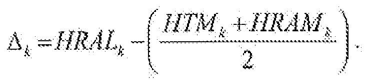
- ➢ during the prior procedure, it is possible to transmit an auxiliary message to each logic entity of the synchronization area, then to record the transmission time (HTMk) of that auxiliary message with respect to the reference clock, in order to communicate it to a selected device (SD) Furthermore, each logic entity can note the local time (HRALk), with respect to its local clock (CLk), when said entity received the auxiliary message, then transmit to the selected device an auxiliary reply message which includes its local time (HRALk). Furthermore, the selected device may note the time (HRAMk), with respect to the reference clock, when it receives every auxiliary reply message from a logic entity of the synchronization area, then it is possible to determine, for each of these logic entities, its gap (Δk) based on the time when the auxiliary message was transmitted (HTMk), the time when its auxiliary reply message was received (HRAMk), and the local time (HRALk) contained within its auxiliary reply message;
- for example, it is possible to determine every gap (Δk) using the formula

- for example, it is possible to determine every gap (Δk) using the formula
- ➢ when a selected packet is received from the broadcast and/or multicast source, each logic entity in the synchronization area may note the time (HLRPk) when that packet was received, with respect to its local clock, and then retransmitting a synchronization message comprising this reception time (HLRPk) to a selected device. For each of the logic entities of the synchronization area, it is then possible to estimate the time (HRRk), with respect to the reference clock, when said entity received that selected packet, based on the gap (Δk) that was determined and on the local time (HLRPk) contained within its received synchronization message;
- The invention further discloses a device for synchronizing radio access logic entities that each have a local clock and form part of a wireless communication network capable of broadcasting and/or multicasting data packets which define content between a broadcast and/or multicast source and mobile communication terminals, via logic entities.
- This synchronization device is characterized in that it comprises calculation means tasked with:
- estimating, for each logic entity (ELk), an area known as a network synchronization area, the time (HRRk), with respect to a reference clock, at which it received a selected packet from the broadcast and/or multicast source, and then
- determining, for each logic entity (ELk) of the synchronization area, a value (Vk) that represents the time difference between its reception time (HRRk) and the latest reception time (HRRk') among those of the radio access logic entities, and
- ordering every logic entity of the synchronization area to wait a period of time equal to the value Vk) which was determined for it before retransmitting each packet received from the broadcast and/or multicast source to the terminals which are located within its synchronization area.
- The inventive device may comprise other characteristics, which may be taken separately or in combination, in particular:
- its calculation means may be tasked with determining, for each logic entity of the synchronization area, during a prior procedure, its local time (HLRk), with respect to the reference clock, then the gap (Δk) between that local time (HLRk) and the time with respect to the reference clock at the moment when this local time (HLRk) was determined;
- ➢ its calculation means may be tasked with estimating, for each logic entity of the synchronization area, during a prior procedure, the time (HRRk), with respect to the reference clock, when said entity received the selected packet, based on its determined gap (Δk) and a local time (HLRPk) contained within a synchronization message, transmitted by the logic entity in response to the receipt of the selected packet, and indicating the reception time of that packet with respect to its local clock;
- its calculation means may be tasked with estimating, for each of said logic entities of the synchronization area, the time (HRRk), with respect to the reference clock, when said entity received that selected packet, by subtracting its determined gap (Δk) from the local time (HLRPk) contained within its received synchronization message;
- ➢ during the prior procedure, its calculation means may be tasked with i) generating, addressed to the logic entities of the synchronization area, an auxiliary message requesting that they transmit their local times when the auxiliary message was received (HRALk) with respect to their local docks (CLk), it) recording the time (HTMk) when that auxiliary message was transmitted, with respect to the reference clock, iii) recording the time (HRAMk) when each auxiliary reply message was received from a logic entity (ELk) of the synchronization area, with respect to the reference clock, and iv) determining, for each of these entities, its gap (Δk) based on the time when the auxiliary message was transmitted (HTMk), the time when its auxiliary reply message was received (HRAMk), and the local time (HRALk) contained within its auxiliary reply message;
- its calculation means may, for example, be tasked with determining each gap (Δk) using the formula

- its calculation means may, for example, be tasked with determining each gap (Δk) using the formula
- ➢ its calculation means may be tasked with estimating, for each logic entity of the synchronization area, during a prior procedure, the time (HRRk), with respect to the reference clock, when said entity received the selected packet, based on its determined gap (Δk) and a local time (HLRPk) contained within a synchronization message, transmitted by the logic entity in response to the receipt of the selected packet, and indicating the reception time of that packet with respect to its local clock;
- The invention further discloses a network device comprising a synchronization device of the type described above.
- Such a device may, for example, constitute a (content-defining) data packet broadcast and/or multicast source for a wireless communication network,
- The invention is particularly well suited, though not exclusively so, to WiMAX local wireless communication networks. However, generally speaking, the invention applies to all types of radio networks that support the broadcast and/or multicast of content data packets, in particular 3GPP MBMS, DVB-H, and WiFi networks (in particular for hard handover roaming).
- Other characteristics and advantages of the invention will become apparent upon examining the detailed description below, and the attached drawing, in which the sole figure schematically and functionally depicts a local wireless communication network comprising a base station equipped with an example embodiment of a synchronization device in accordance with the invention.
- The attached drawing may serve not only to complete the invention, but may also contribute to defining it, if need be.
- The object of the invention is to enable the synchronization of radio access logic entities, which form part of a wireless communication network.
- In the following, it is assumed by way of a non-limiting example that the wireless communication network is a WiMAX local radio network. However, the invention the invention is not limited to this type of wireless communication network. Indeed, it pertains to all cellular (or mobile) networks (such as GSM, GPRS/EDGE, UMTS or CDMA (2000) networks), and WLANs (or "Wireless Local Area Networks" such as WiMAX (a collection of the IEEE 802.16 and HiperMan standards, in particular) Wi-Fi (the IEEE 802.11g standard), ETSI HiperLAN/2 or those compliant with the 802.11a standard), so long as it is capable of broadcasting and/or multicasting content data (potentially multimedia content data) to mobile (or cellular or portable) communication terminals via unsynchronized radio access logic entities.
- Furthermore, in the following, it is assumed by way of a non-limiting example that the communication terminals (MS) are mobile (or cellular) telephones. However, the invention is not limited to this type of communication terminal. Indeed, it pertains to any mobile (or portable or cellular) radio communication device with a wireless communication interface, which is at least capable of receiving data (which defines content, potentially multimedia content (such as television or radio programs or videos) transmitted by waves. Consequently, it may also, in particular, be a laptop computer, or a personal digital assistant (or PDA), so long as it is equipped with radio or satellite communication means.
- As is schematically and functionally depicted in the sole figure, a wireless local network (here a WiMAX network), implementing a content broadcasting and/or multicasting service (potentially an MBS ("Multicast Broadcast Service")), comprises at least a radio access network RA, generally known as an ASN ("Access Service Network"), which the terminals MS may connect to, and a core network CN coupled to the radio access network RA, to which one or more content servers (or sources) SC may be coupled (or connected).
- The radio access network RA particularly comprises at least one base station (or access point) SBi, generally known as a BS ("Base Station"), by which the terminals MS may connect to the wireless local network, and at least one broadcast and/or multicast source SD coupled to at least one of the base stations SBi.
- The broadcast and/or multicast source SD may, for example, be a radio network controller. If so, it is particularly tasked with broadcasting and/or multicasting data packets that define content to be broadcast and/or multicast, which are transmitted to it by a content server (or source) SC, to one or more base stations SBi tasked with broadcasting and/or multicasting that same content to terminals MS which are located within its (or their) coverage area. However, the broadcast and/or multicast source DS may also be a content server (or source).
- For example, the content may be television or music programs, or videos. However, the invention pertains to all types of content.
- Each base station SBi comprises at least one radio access logic entity ELk. As a reminder, the term "radio access logic entity" here refers to a network device that sets access to radio resources (i.e. is capable of changing the characteristics of the physical later and the associated data link layer) of a radio access network RA.
- In the following, it is assumed, by way of an illustrative and non-limiting example, that the logic entities ELk are (single-sector) antennas. However, a logic entity may also be one sector of a multi-sector antenna, or a particular range of frequencies (if the technology supports multiple different ranges of frequencies to define the channels), for example.
- Each logic entity (here, an antenna) ELk comprises a buffer memory, in which it may store data packets from the broadcast and/or multicast source SD, and a local clock CLk. It is further capable of scheduling the transmission of packets to terminals MS of its synchronization area ZS, over the radio interface, said packets being stored in its buffer memory, potentially based on their sequencing (defined by their sequence number, for transmission via GRE tunnels (or a similar technology, such as incremental IPv4 identifiers or 3GPP frame protocol sequence numbers).
- It should be noted that it is necessary to be able to "identify" the content data packets between the broadcast and/or multicast source SD and the antennas of the radio access network RA. The notion of sequencing is not strictly necessary for the invention. However, it is necessary that all the antennas of an area known as the "synchronization area" (defined above) are capable of noting the time when a single selected packed was received (HLRPk-defined below).
- In the non-limiting example depicted, three base stations SB1 to SB3 (i = 1 to 3), each comprising a single logic entity ELk (k = 1 to 3) have been illustrated. However, the invention applies so long as the radio access network RA comprises at least two logic entities ELk located within a single synchronization area ZS, and potentially installed within a single base station SBi.
- Here, the term "synchronization area" refers to a geographic area within which the same content is broadcast and/or multicast, and within which the terminals MS may perform handovers without becoming disconnected from the content broadcasting and/or multicasting service (for example, MBS) in normal operating mode.
- In order to synchronize the logic entities ELk (here, antennas) of a synchronization area ZS, the invention discloses a synchronization device D. As depicted in the sole figure, such a device D comprises at least one calculating module MC tasked with acting each time a synchronization is requested. Preferably, this action takes place periodically, such as every hour. However, this is not mandatory. It may instead by triggered on request, such as one sent from the network's operator.
- It should be noted that in the non-limiting example depicted, the device D is advantageously installed within the broadcast and/or multicast source SD which supplies the base stations SBi of a synchronization area ZS (to which it is connected, as here it constitutes a radio network controller, though in a non-limiting fashion) with (IP) data packets to be broadcast and/or multicast. However, this is not mandatory. The device D may instead be installed in another network device coupled to a broadcast and/or multicast source SD, or constitute a network device coupled to at least one broadcast and/or multicast source SD.
- Each time it acts, the calculating module MC estimates, for each logic entity ELk of a synchronization area ZS of the network, the time HRRk when said entity received a selected packed from the broadcast and/or multicast source SD. Each of these times HRRk is defined by a single reference clock CR. This clock may, for example, be the local clock of the broadcast and/or multicast source SD (as depicted in the sole figure). However, this is not mandatory. In the event of periodic operation, a content data packet every N is used to automatically trigger a synchronization. An example method for obtaining these times HRRk shall be described later.
- Next, for each logic entity ELk of the synchronization area ZS in question (potentially the only one), the calculating module MC determines a value Vk representing the time difference between its reception time HRRk and the latest reception time HRRk' among all of the various logic entities of the synchronization area ZS in question. An example method for obtaining these values Vk shall be described later.
- Finally, the calculating module MC generates, for each logic entity ELk of the synchronization area ZS in question, a message ordering it to wait for a period of time equal to the value Vk which was determined for it before retransmitting each content (IP) data packet that it receives from the broadcast and/or multicast source SD to the terminals MS which are located within its synchronization area ZS.
- It should be understood that each logic entity ELk will then store each received content IP packet in its buffer memory, for a period of time equal to the value Vk, before retransmitting it to the terminals MS.
- By using this mechanism for synchronizing the logic entities ELk of a synchronization area ZS, said entities may now retransmit a single content IP packet received from a broadcast and/or multicast source at roughly the same time, thereby preventing a terminal MS from losing multiple content IP packets, or from receiving duplicate content IP pockets, during a handover procedure.
- To obtain the times HRRk, the calculating module MC may, for example, implement the method described above. It relies upon previously knowing the gap Δk between the local time HLRk of each logic entity ELk (defined by its local clock CLk) and the time HR with respect to the reference clock CR at the moment when this local time HLRk was determined.
- This prior knowledge of the various gaps Δk may be obtained during a so-called acquisition procedure, which may potentially be carried out periodically, such as by using the same interval as the one used for synchronizing the logic entities ELk. It should be understood that each acquisition procedure must proceed prior to a synchronization procedure whose gaps Δk it provides.
- Each acquisition procedure is carried out by the device D for its own synchronization area ZS. It consists of first determining, for each logic entity ELk of the synchronization area ZS in question, its local time HLRk with respect to the reference clock CR which is associated with that synchronization area ZS in question. To do so, it is possible, for example, to transmit an auxiliary message MA to the various logic entities ELk of the synchronization area ZS, and to record the time HTMk when this auxiliary message MA was transmitted with respect to the reference clock CR.
- This auxiliary message MA is preferentially generated by the device D and transmitted by the broadcast and/or multicast source SD to the various logic entities ELk of the synchronization area ZS in question. Furthermore, it's the broadcast and/or multicast source SD which notes the time HTMk when an auxiliary message MA is transmitted when compared with its reference clock CR, and which provides it to the device D.
- Each logic entity ELk which receives an auxiliary message MA notes its local reception time HRALk. It should be understood that each local reception time HRALk is defined by the local clock CLk of the logic entity ELk. Once the logic entity ELk has noted its local reception time HRALk, it transmits it to a selected network device, which is preferably the one which transmitted the auxiliary message MA (here, the broadcast and/or multicast source SD), by means of an auxiliary reply message MRAk.
- When the selected network device receives an auxiliary reply message MRAk, it notes the reception time HRAMk. It should be understood that each reception time HRAMk is defined by the reference clock CR. This is why it is preferable that it be the same network device that transmits the auxiliary message MA and receives the auxiliary reply messages MRAk. In other words, it is advantageous that the selected network device be the broadcast and/or multicast source SD.
- The selected network device that receives the auxiliary reply messages MRAk (here, the broadcast and/or multicast source SD) transmits the reception times HRAMk of these auxiliary reply messages MRAk to the device D, so that its calculating module MC may determine, for each logic entity ELk of the synchronization area ZS in question its gap Δk, based on the time HTMk when the auxiliary message MA was transmitted, the time HRAMk when its auxiliary reply message MRAk was received, and the local time HRALk contained within its auxiliary reply message MRAk.
- For example, the calculating module MC may determine each gap Δk by means of the formula

- Once the calculating module MC has the gaps Δk, it may obtain the times HRRk needed for the synchronization procedure.
- Each synchronization procedure is automatically triggered when the logic entities ELk receive a single selected packet from the broadcast and/or multicast source SD.
- When such a packet (for example, a content IP packet every N) is received, each logic entity ELk of a synchronization area ZS notes the time HLRPk when that packet was received, with respect to its local clock CLk. Next, each logic entity ELk of that synchronization area ZS generates a synchronization message MRk comprising its own reception time HLRPk and transmits it to a selected device, for example the broadcast and/or multicast source SD (or the device D itself).
- When the selected network device receives a synchronization message MRk, it communicates it to the device D so that its calculating module MC estimates, for each logic entity EHk of the synchronization area ZS in question, the time HRRk (defined by the reference clock CR) when said entity received the selected packet, based on its gap Δk (determined during the acquisition procedure) and the local time HLRPk contained within its received synchronization message MRk.
- For example, the calculating module MC may determine each time HRRk using the non-limiting formula HRRk =HLRPk -Δ k . It should be noted that the time HRRk constitutes a sort of corrected local reception time within a logic entity ELk, i.e, the one with respect to the reference clock CR.
- To obtain the aforementioned values Vk during a synchronization procedure, the calculating module MC may, for example, implement the method described above. First, it gathers all of the reception times HRRk of the various logic entities ELk of the synchronization area ZS in question. Next, it determines which one is the latest, such as by using the formula MAX[X]=max({HRR k[X]}), were X refers to the originally selected packet of the synchronization procedure and HRRk [X] refers to the reception time HRRk for the selected packet X in question, Each value Vk is then with respect to the formula Vk =MAX[X]-HRRk [X].
- It is important to note that a device D may act upon a single synchronization area, or upon multiple different synchronization areas (centralized operation).
- Furthermore, the inventive synchronization device D, and in particular its calculation module MC and, if applicable, its storage module MM, may be constructed in the form of electronic circuits, software (or computing) modules, or a combination of circuits and software.
- It is also important to note that the invention may also be considered to be a method for synchronizing logic entities ELk which may, in particular, be implemented by means of a synchronization device D as described above, As the functionalities afforded by the implementation of the inventive method are identical to those afforded by the device D described above, only the combination of main functionalities afforded by the method is described above.
- This synchronization method comprises the steps of:
- estimating, for each logic entity ELk of a synchronization area ZS of the network, the time HRRk, with respect to the reference clock CR, when said entity received a selected packet from the broadcast and/or multicast source SD, then
- - determining, for each logic entity ELk, of the synchronization area, a value Vk that represents the time difference between its reception time HRRk and the latest reception time HRRk. among those of the radio access logic entities, and
- - ordering each logic entity ELk of the synchronization area ZE to wait for a period of time equal to the value Vk which has been determined for it before retransmitting each packet received from the broadcast and/or multicast source SD to the terminals MS which are located within its synchronization area ZS.
- The invention is particularly advantageous because it operates within the application layer, and therefore has no impact on the transporting of the packets (naturally, not including the time difference in their retransmission by the various logic entities ELk based on the values Vk).
- The invention is not limited to the embodiments of the synchronization device, network device, and synchronization method described above, which are given only by way of example; rather, it encompasses all variations that a person skilled in the art may envision within the framework of the claims below.
Claims (14)
- A method for synchronizing radio access logic entities (ELk) each having a local clock (CLk) and forming part of a wireless communication network capable of broadcasting and/or multicasting content-defining data packets between a broadcast and/or multicast source (SD) and mobile communication terminals (MS), via said logic entities (ELk), characterized in that it comprises the steps of i) estimating, for each logic entity (ELk) of a so-called synchronization area (ZS) of said network, the time (HRRk), with respect to a reference clock (CR), when said entity received a selected packet from said broadcasting and/or multicasting source (SD), and then ii) determining, for each logic entity (ELk) of said synchronization area (ZS), a value (Vk) representative of the time difference between its reception time (HRRk) and the latest reception time (HRRk) among those of said logic entities, and iii) ordering each logic entity (ELk) of said synchronization area (Zs) to wait for a period of time equal to the value (Vk) which was determined for it before retransmitting each packet received from said broadcast and/or multicast source (SD) to the terminals (MS) located within its synchronization area (ZS).
- A method according to claim 1, characterized in that for each logic entity (ELk) of said synchronization area (ZS), during a prior procedure the following are determined: its local time (HLRk) with respect to said reference clock (CR), then the gap (Δk) between that local time (HLRk) and the time (HR) with respect to said reference clock (CR) at the moment when said local time (HLRk) is determined.
- A method according to claim 2, characterized in that when a selected packet is received from said broadcast and/or multicast source (SD), each logic entity (ELk) of said synchronization area (ZS) notes the time (HLRPk) when said packet was received, with respect to its local clock (CLk), then transmits a synchronization message comprising said reception time (HLRPk) to a selected device (SD), and in that, for each of said logic entities (ELk) of said synchronization area (ZS), the time (HRRk), with respect to said reference clock (CR), when said entity received said selected packet is estimated, based on its determined gap (Δk) and the local time (HLRPk) contained within its received synchronization message.
- A method according to claim 3, characterized in that, for each of said logic entities (ELk) of said synchronization area (ZS) the time (HRRk), with respect to said reference clock (CR), when said entity received said selected packet is estimated by subtracting its determined gap (Δk) from the local time (HLRPk) contained within its received synchronization message.
- A method according to any of claims 2 to 4, characterized in that during said prior procedure, an auxiliary message is transmitted to each logic entity (ELk) of said synchronization area (ZS), the time (HTMk) when this auxiliary message is transmitted, with respect to said reference clock (CR), is recorded, and this auxiliary message is then communicated to a selected device (SD), in that each logic entity (ELk) notes the local time (HRALk), with respect to its local clock (CLk), when it receives said auxiliary message, then transmits to said selected device (SD) an auxiliary reply message including said local time (HRALk), and in that said selected device (SD) notes the time (HRAMk), with respect to said reference clock (CR), when it receives each auxiliary reply message from a logic entity (ELk) of said synchronization area (ZS), then, for each of these logic entities (ELk), its gap (Δk) is determined based on said transmission time of the auxiliary message (HTMk), said reception time of the auxiliary message (HRAMk) and said local time (HRALk) contained within its auxiliary reply message.
- A method according to claim 5, characterized in that each gap (Δk) is determined using the formula

- A device (D) for synchronizing radio access logic entities (ELk) each having a local clock (CLk) and forming part of a wireless communication network capable of broadcasting and/or multicasting content-defining data packets between a broadcast and/or multicast source (SD) and mobile communication terminals (MS), via logic entities (ELk), characterized in that is comprises calculation means (MC) configured to i) estimate, for each logic entity (ELk) of a so-called synchronization area (ZS) of said network, the time (HRRk), with respect to a reference clock (CR), when said entity received a selected packet from said broadcast and/or multicast source (SD), and then to ii) determine, for each logic entity (ELk) of said synchronization area (ZS), a value (Vk) representative of the time difference between its reception time (HRRk) and the latest reception time (HRRk) among those of said logic entities, and to iii) order each logic entity (ELk) of said synchronization area (Zs) to wait for a period of time equal to the value (Vk) which was determined for it before retransmitting each packet received from said broadcast and/or multicast source (SD) to the terminals (MS) located within its synchronization area (ZS).
- A device according to claim 7, characterized in that said calculation means (MC) are configured to determine, for each logic entity (ELk) of said synchronization area (ZS), during a prior procedure: its local time (HLRk) with respect to said reference clock (CR), then the gap (Δk) between that local time (HLRk) and the time (HR) with respect to said reference clock (CR) at the moment when said local time (HLRk) is determined.
- A device according to claim 8, characterized in that said calculation means (MC) are configured to estimate, for each of said logic entities (ELk) of said synchronization area (ZS), the time (HRRk), with respect to said reference clock (CR), when said entity received said selected packet, based on its determined gap (Δk) and the local time (HLRPk) contained within its received synchronization message transmitted by said logic entity (ELk) in response to the reception of said selected packet, and indicating the time when said packet was received with respect to its local clock (CLk).
- A device according to claim 9, characterized in that said calculation means (MC) are configured to estimate, for each of said logic entities (ELk) of said synchronization area (ZS) the time (HRRk), with respect to said reference clock (CR), when said entity received said selected packet, by subtracting its determined gap (Δk) from the local time (HLRPk) contained within its received synchronization message.
- A device according to any of claims 8 to 10, characterized in that during said previous procedure, said calculation means (MC) are configured to i) generate, addressed to said logical entities (ELk) of said synchronization area (ZS), an auxiliary message requesting that they transmit their local times when the auxiliary message was received (HRALk) with respect to their local clocks (CLk), ii) record the time (HTMk) when that auxiliary message was transmitted, with respect to the reference clock, iii) record the time (HRAMk) when each auxiliary reply message was received from a logic entity (ELk) of the synchronization area, with respect to the reference clock, and iv) determining, for each of these entities, its gap (Δk) based on the time when the auxiliary message was transmitted (HTMk), the time when its auxiliary reply message was received (HRAMk), and the local time (HRALk) contained within its auxiliary reply message
- A device according to claim 11, characterized in that said calculation means (CM) are configured to determine each gap (Δk) by means of the formula
- A network device (SD), characterized in that it comprises a synchronization device (D) according to any of claims 7 to 12.
- A network device according to claim 13, characterized in that it constitutes a broadcast and/or multicast source (SD) of content-defining data packets for a wireless communication network.
Applications Claiming Priority (1)
| Application Number | Priority Date | Filing Date | Title |
|---|---|---|---|
| FR0759417A FR2924545B1 (en) | 2007-11-29 | 2007-11-29 | DEVICE AND METHOD FOR SYNCHRONIZING RADIO ACCESS LOGIC ENTITIES OF A WIRELESS COMMUNICATION NETWORK |
Publications (2)
| Publication Number | Publication Date |
|---|---|
| EP2066050A1 true EP2066050A1 (en) | 2009-06-03 |
| EP2066050B1 EP2066050B1 (en) | 2012-05-30 |
Family
ID=39563336
Family Applications (1)
| Application Number | Title | Priority Date | Filing Date |
|---|---|---|---|
| EP08170088A Active EP2066050B1 (en) | 2007-11-29 | 2008-11-27 | Device and method for synchronizing radio access logic entities of a wireless communication network |
Country Status (4)
| Country | Link |
|---|---|
| US (1) | US20090141664A1 (en) |
| EP (1) | EP2066050B1 (en) |
| FR (1) | FR2924545B1 (en) |
| WO (1) | WO2009068607A1 (en) |
Citations (4)
| Publication number | Priority date | Publication date | Assignee | Title |
|---|---|---|---|---|
| WO1993025012A1 (en) * | 1992-05-29 | 1993-12-09 | Motorola, Inc. | Method and apparatus for synchronizing a simulcast transmission system |
| US5485632A (en) * | 1993-02-26 | 1996-01-16 | Motorola, Inc. | Method for initiating and determining simulcast transmission of a message |
| US20050163064A1 (en) * | 2004-01-27 | 2005-07-28 | Samsung Electronics Co., Ltd. | Synchronization apparatus and method for broadcasting a service stream in a mobile communication system |
| US20070171853A1 (en) * | 2006-01-23 | 2007-07-26 | Ipwireless, Inc. | Quasi synchronous transmission in cellular networks |
Family Cites Families (1)
| Publication number | Priority date | Publication date | Assignee | Title |
|---|---|---|---|---|
| JP4866690B2 (en) * | 2006-09-11 | 2012-02-01 | 富士通株式会社 | Preamble receiver |
-
2007
- 2007-11-29 FR FR0759417A patent/FR2924545B1/en not_active Expired - Fee Related
-
2008
- 2008-11-26 US US12/292,824 patent/US20090141664A1/en not_active Abandoned
- 2008-11-27 EP EP08170088A patent/EP2066050B1/en active Active
- 2008-11-27 WO PCT/EP2008/066326 patent/WO2009068607A1/en active Application Filing
Patent Citations (4)
| Publication number | Priority date | Publication date | Assignee | Title |
|---|---|---|---|---|
| WO1993025012A1 (en) * | 1992-05-29 | 1993-12-09 | Motorola, Inc. | Method and apparatus for synchronizing a simulcast transmission system |
| US5485632A (en) * | 1993-02-26 | 1996-01-16 | Motorola, Inc. | Method for initiating and determining simulcast transmission of a message |
| US20050163064A1 (en) * | 2004-01-27 | 2005-07-28 | Samsung Electronics Co., Ltd. | Synchronization apparatus and method for broadcasting a service stream in a mobile communication system |
| US20070171853A1 (en) * | 2006-01-23 | 2007-07-26 | Ipwireless, Inc. | Quasi synchronous transmission in cellular networks |
Also Published As
| Publication number | Publication date |
|---|---|
| WO2009068607A1 (en) | 2009-06-04 |
| FR2924545B1 (en) | 2009-12-11 |
| FR2924545A1 (en) | 2009-06-05 |
| US20090141664A1 (en) | 2009-06-04 |
| EP2066050B1 (en) | 2012-05-30 |
Similar Documents
| Publication | Publication Date | Title |
|---|---|---|
| US8310972B2 (en) | Mobile wireless communication system, access gateway, wireless base station, and mobile wireless communication control method | |
| CN101395824B (en) | Method, root node and base station for quasi synchronous transmission in cellular networks | |
| US7283815B2 (en) | Method for maximizing gain of received signal in a multimedia broadcast/multicast service system | |
| US8843118B2 (en) | Multi-cell coordination for multimedia broadcast multicast services in a wireless communication system | |
| US8781455B2 (en) | Method to control configuration change times in a wireless device | |
| EP2621232A1 (en) | Multi-cell coordination for multimedia broadcast muliticast services in a wireless communication system. | |
| US9277372B2 (en) | File scheduling in BM-SC | |
| EP3422804B1 (en) | Multicast transmission method, base station, and user equipment | |
| EP2316235B1 (en) | A method of transmitting cell identity information | |
| RU2435326C2 (en) | Method of synchronisation of broadcasting/multi-address transfer of multimedia information | |
| EP3085012B1 (en) | Feedback based adaptation of multicast transmission offset | |
| EP2066050B1 (en) | Device and method for synchronizing radio access logic entities of a wireless communication network | |
| EP2207279A1 (en) | Method for transmitting uplink data in a communications system | |
| CN113661746B (en) | Information configuration method and device, terminal equipment and network equipment | |
| US20090028085A1 (en) | Method for providing measurement gaps | |
| KR20150044213A (en) | Scheme for supporting transceiving mbms service packet in a wireless communication system | |
| WO2014040257A1 (en) | Method and device for transmitting data |
Legal Events
| Date | Code | Title | Description |
|---|---|---|---|
| PUAI | Public reference made under article 153(3) epc to a published international application that has entered the european phase |
Free format text: ORIGINAL CODE: 0009012 |
|
| AK | Designated contracting states |
Kind code of ref document: A1 Designated state(s): AT BE BG CH CY CZ DE DK EE ES FI FR GB GR HR HU IE IS IT LI LT LU LV MC MT NL NO PL PT RO SE SI SK TR |
|
| AX | Request for extension of the european patent |
Extension state: AL BA MK RS |
|
| 17P | Request for examination filed |
Effective date: 20091203 |
|
| AKX | Designation fees paid |
Designated state(s): AT BE BG CH CY CZ DE DK EE ES FI FR GB GR HR HU IE IS IT LI LT LU LV MC MT NL NO PL PT RO SE SI SK TR |
|
| 17Q | First examination report despatched |
Effective date: 20100302 |
|
| GRAP | Despatch of communication of intention to grant a patent |
Free format text: ORIGINAL CODE: EPIDOSNIGR1 |
|
| RAP1 | Party data changed (applicant data changed or rights of an application transferred) |
Owner name: ALCATEL LUCENT |
|
| GRAS | Grant fee paid |
Free format text: ORIGINAL CODE: EPIDOSNIGR3 |
|
| GRAA | (expected) grant |
Free format text: ORIGINAL CODE: 0009210 |
|
| AK | Designated contracting states |
Kind code of ref document: B1 Designated state(s): AT BE BG CH CY CZ DE DK EE ES FI FR GB GR HR HU IE IS IT LI LT LU LV MC MT NL NO PL PT RO SE SI SK TR |
|
| REG | Reference to a national code |
Ref country code: GB Ref legal event code: FG4D |
|
| REG | Reference to a national code |
Ref country code: CH Ref legal event code: EP |
|
| REG | Reference to a national code |
Ref country code: AT Ref legal event code: REF Ref document number: 560478 Country of ref document: AT Kind code of ref document: T Effective date: 20120615 |
|
| REG | Reference to a national code |
Ref country code: IE Ref legal event code: FG4D |
|
| REG | Reference to a national code |
Ref country code: DE Ref legal event code: R096 Ref document number: 602008015996 Country of ref document: DE Effective date: 20120802 |
|
| REG | Reference to a national code |
Ref country code: NL Ref legal event code: VDEP Effective date: 20120530 |
|
| REG | Reference to a national code |
Ref country code: LT Ref legal event code: MG4D Effective date: 20120530 |
|
| PG25 | Lapsed in a contracting state [announced via postgrant information from national office to epo] |
Ref country code: NO Free format text: LAPSE BECAUSE OF FAILURE TO SUBMIT A TRANSLATION OF THE DESCRIPTION OR TO PAY THE FEE WITHIN THE PRESCRIBED TIME-LIMIT Effective date: 20120830 Ref country code: CY Free format text: LAPSE BECAUSE OF FAILURE TO SUBMIT A TRANSLATION OF THE DESCRIPTION OR TO PAY THE FEE WITHIN THE PRESCRIBED TIME-LIMIT Effective date: 20120530 Ref country code: IS Free format text: LAPSE BECAUSE OF FAILURE TO SUBMIT A TRANSLATION OF THE DESCRIPTION OR TO PAY THE FEE WITHIN THE PRESCRIBED TIME-LIMIT Effective date: 20120930 Ref country code: FI Free format text: LAPSE BECAUSE OF FAILURE TO SUBMIT A TRANSLATION OF THE DESCRIPTION OR TO PAY THE FEE WITHIN THE PRESCRIBED TIME-LIMIT Effective date: 20120530 Ref country code: SE Free format text: LAPSE BECAUSE OF FAILURE TO SUBMIT A TRANSLATION OF THE DESCRIPTION OR TO PAY THE FEE WITHIN THE PRESCRIBED TIME-LIMIT Effective date: 20120530 Ref country code: LT Free format text: LAPSE BECAUSE OF FAILURE TO SUBMIT A TRANSLATION OF THE DESCRIPTION OR TO PAY THE FEE WITHIN THE PRESCRIBED TIME-LIMIT Effective date: 20120530 |
|
| REG | Reference to a national code |
Ref country code: AT Ref legal event code: MK05 Ref document number: 560478 Country of ref document: AT Kind code of ref document: T Effective date: 20120530 |
|
| PG25 | Lapsed in a contracting state [announced via postgrant information from national office to epo] |
Ref country code: SI Free format text: LAPSE BECAUSE OF FAILURE TO SUBMIT A TRANSLATION OF THE DESCRIPTION OR TO PAY THE FEE WITHIN THE PRESCRIBED TIME-LIMIT Effective date: 20120530 Ref country code: GR Free format text: LAPSE BECAUSE OF FAILURE TO SUBMIT A TRANSLATION OF THE DESCRIPTION OR TO PAY THE FEE WITHIN THE PRESCRIBED TIME-LIMIT Effective date: 20120831 Ref country code: LV Free format text: LAPSE BECAUSE OF FAILURE TO SUBMIT A TRANSLATION OF THE DESCRIPTION OR TO PAY THE FEE WITHIN THE PRESCRIBED TIME-LIMIT Effective date: 20120530 Ref country code: HR Free format text: LAPSE BECAUSE OF FAILURE TO SUBMIT A TRANSLATION OF THE DESCRIPTION OR TO PAY THE FEE WITHIN THE PRESCRIBED TIME-LIMIT Effective date: 20120530 |
|
| PG25 | Lapsed in a contracting state [announced via postgrant information from national office to epo] |
Ref country code: BE Free format text: LAPSE BECAUSE OF FAILURE TO SUBMIT A TRANSLATION OF THE DESCRIPTION OR TO PAY THE FEE WITHIN THE PRESCRIBED TIME-LIMIT Effective date: 20120530 |
|
| PG25 | Lapsed in a contracting state [announced via postgrant information from national office to epo] |
Ref country code: SK Free format text: LAPSE BECAUSE OF FAILURE TO SUBMIT A TRANSLATION OF THE DESCRIPTION OR TO PAY THE FEE WITHIN THE PRESCRIBED TIME-LIMIT Effective date: 20120530 Ref country code: AT Free format text: LAPSE BECAUSE OF FAILURE TO SUBMIT A TRANSLATION OF THE DESCRIPTION OR TO PAY THE FEE WITHIN THE PRESCRIBED TIME-LIMIT Effective date: 20120530 Ref country code: RO Free format text: LAPSE BECAUSE OF FAILURE TO SUBMIT A TRANSLATION OF THE DESCRIPTION OR TO PAY THE FEE WITHIN THE PRESCRIBED TIME-LIMIT Effective date: 20120530 Ref country code: EE Free format text: LAPSE BECAUSE OF FAILURE TO SUBMIT A TRANSLATION OF THE DESCRIPTION OR TO PAY THE FEE WITHIN THE PRESCRIBED TIME-LIMIT Effective date: 20120530 Ref country code: NL Free format text: LAPSE BECAUSE OF FAILURE TO SUBMIT A TRANSLATION OF THE DESCRIPTION OR TO PAY THE FEE WITHIN THE PRESCRIBED TIME-LIMIT Effective date: 20120530 Ref country code: CZ Free format text: LAPSE BECAUSE OF FAILURE TO SUBMIT A TRANSLATION OF THE DESCRIPTION OR TO PAY THE FEE WITHIN THE PRESCRIBED TIME-LIMIT Effective date: 20120530 Ref country code: DK Free format text: LAPSE BECAUSE OF FAILURE TO SUBMIT A TRANSLATION OF THE DESCRIPTION OR TO PAY THE FEE WITHIN THE PRESCRIBED TIME-LIMIT Effective date: 20120530 |
|
| PG25 | Lapsed in a contracting state [announced via postgrant information from national office to epo] |
Ref country code: IT Free format text: LAPSE BECAUSE OF FAILURE TO SUBMIT A TRANSLATION OF THE DESCRIPTION OR TO PAY THE FEE WITHIN THE PRESCRIBED TIME-LIMIT Effective date: 20120530 Ref country code: PL Free format text: LAPSE BECAUSE OF FAILURE TO SUBMIT A TRANSLATION OF THE DESCRIPTION OR TO PAY THE FEE WITHIN THE PRESCRIBED TIME-LIMIT Effective date: 20120530 Ref country code: PT Free format text: LAPSE BECAUSE OF FAILURE TO SUBMIT A TRANSLATION OF THE DESCRIPTION OR TO PAY THE FEE WITHIN THE PRESCRIBED TIME-LIMIT Effective date: 20121001 |
|
| PLBE | No opposition filed within time limit |
Free format text: ORIGINAL CODE: 0009261 |
|
| STAA | Information on the status of an ep patent application or granted ep patent |
Free format text: STATUS: NO OPPOSITION FILED WITHIN TIME LIMIT |
|
| PG25 | Lapsed in a contracting state [announced via postgrant information from national office to epo] |
Ref country code: ES Free format text: LAPSE BECAUSE OF FAILURE TO SUBMIT A TRANSLATION OF THE DESCRIPTION OR TO PAY THE FEE WITHIN THE PRESCRIBED TIME-LIMIT Effective date: 20120910 |
|
| 26N | No opposition filed |
Effective date: 20130301 |
|
| REG | Reference to a national code |
Ref country code: CH Ref legal event code: PL |
|
| REG | Reference to a national code |
Ref country code: DE Ref legal event code: R097 Ref document number: 602008015996 Country of ref document: DE Effective date: 20130301 |
|
| PG25 | Lapsed in a contracting state [announced via postgrant information from national office to epo] |
Ref country code: LI Free format text: LAPSE BECAUSE OF NON-PAYMENT OF DUE FEES Effective date: 20121130 Ref country code: BG Free format text: LAPSE BECAUSE OF FAILURE TO SUBMIT A TRANSLATION OF THE DESCRIPTION OR TO PAY THE FEE WITHIN THE PRESCRIBED TIME-LIMIT Effective date: 20120830 Ref country code: CH Free format text: LAPSE BECAUSE OF NON-PAYMENT OF DUE FEES Effective date: 20121130 |
|
| REG | Reference to a national code |
Ref country code: IE Ref legal event code: MM4A |
|
| PG25 | Lapsed in a contracting state [announced via postgrant information from national office to epo] |
Ref country code: IE Free format text: LAPSE BECAUSE OF NON-PAYMENT OF DUE FEES Effective date: 20121127 |
|
| REG | Reference to a national code |
Ref country code: FR Ref legal event code: GC Effective date: 20131018 |
|
| PG25 | Lapsed in a contracting state [announced via postgrant information from national office to epo] |
Ref country code: MT Free format text: LAPSE BECAUSE OF FAILURE TO SUBMIT A TRANSLATION OF THE DESCRIPTION OR TO PAY THE FEE WITHIN THE PRESCRIBED TIME-LIMIT Effective date: 20120530 |
|
| PG25 | Lapsed in a contracting state [announced via postgrant information from national office to epo] |
Ref country code: MC Free format text: LAPSE BECAUSE OF NON-PAYMENT OF DUE FEES Effective date: 20121130 Ref country code: TR Free format text: LAPSE BECAUSE OF FAILURE TO SUBMIT A TRANSLATION OF THE DESCRIPTION OR TO PAY THE FEE WITHIN THE PRESCRIBED TIME-LIMIT Effective date: 20120530 |
|
| PG25 | Lapsed in a contracting state [announced via postgrant information from national office to epo] |
Ref country code: LU Free format text: LAPSE BECAUSE OF NON-PAYMENT OF DUE FEES Effective date: 20121127 |
|
| PG25 | Lapsed in a contracting state [announced via postgrant information from national office to epo] |
Ref country code: HU Free format text: LAPSE BECAUSE OF FAILURE TO SUBMIT A TRANSLATION OF THE DESCRIPTION OR TO PAY THE FEE WITHIN THE PRESCRIBED TIME-LIMIT Effective date: 20081127 |
|
| REG | Reference to a national code |
Ref country code: FR Ref legal event code: RG Effective date: 20141016 |
|
| REG | Reference to a national code |
Ref country code: FR Ref legal event code: PLFP Year of fee payment: 8 |
|
| REG | Reference to a national code |
Ref country code: FR Ref legal event code: PLFP Year of fee payment: 9 |
|
| REG | Reference to a national code |
Ref country code: FR Ref legal event code: PLFP Year of fee payment: 10 |
|
| REG | Reference to a national code |
Ref country code: DE Ref legal event code: R082 Ref document number: 602008015996 Country of ref document: DE Representative=s name: METACOM LEGAL RECHTSANWAELTE, DE Ref country code: DE Ref legal event code: R082 Ref document number: 602008015996 Country of ref document: DE Representative=s name: METACOM LEGAL, DE Ref country code: DE Ref legal event code: R081 Ref document number: 602008015996 Country of ref document: DE Owner name: WSOU INVESTMENTS, LLC, LOS ANGELES, US Free format text: FORMER OWNER: ALCATEL LUCENT, PARIS, FR Ref country code: DE Ref legal event code: R082 Ref document number: 602008015996 Country of ref document: DE Representative=s name: BARKHOFF REIMANN VOSSIUS, DE |
|
| REG | Reference to a national code |
Ref country code: GB Ref legal event code: 732E Free format text: REGISTERED BETWEEN 20200924 AND 20200930 |
|
| REG | Reference to a national code |
Ref country code: DE Ref legal event code: R082 Ref document number: 602008015996 Country of ref document: DE Representative=s name: METACOM LEGAL RECHTSANWAELTE, DE Ref country code: DE Ref legal event code: R082 Ref document number: 602008015996 Country of ref document: DE Representative=s name: METACOM LEGAL, DE |
|
| PGFP | Annual fee paid to national office [announced via postgrant information from national office to epo] |
Ref country code: GB Payment date: 20230327 Year of fee payment: 15 |
|
| P01 | Opt-out of the competence of the unified patent court (upc) registered |
Effective date: 20230606 |
|
| PGFP | Annual fee paid to national office [announced via postgrant information from national office to epo] |
Ref country code: FR Payment date: 20230425 Year of fee payment: 15 Ref country code: DE Payment date: 20230427 Year of fee payment: 15 |