EP2065967B1 - Bandpass filter - Google Patents
Bandpass filter Download PDFInfo
- Publication number
- EP2065967B1 EP2065967B1 EP20070291436 EP07291436A EP2065967B1 EP 2065967 B1 EP2065967 B1 EP 2065967B1 EP 20070291436 EP20070291436 EP 20070291436 EP 07291436 A EP07291436 A EP 07291436A EP 2065967 B1 EP2065967 B1 EP 2065967B1
- Authority
- EP
- European Patent Office
- Prior art keywords
- band
- resonant
- filter
- resonant cavities
- pass
- Prior art date
- Legal status (The legal status is an assumption and is not a legal conclusion. Google has not performed a legal analysis and makes no representation as to the accuracy of the status listed.)
- Active
Links
- 238000001914 filtration Methods 0.000 claims description 3
- 230000005540 biological transmission Effects 0.000 description 38
- 230000003595 spectral effect Effects 0.000 description 33
- 238000004891 communication Methods 0.000 description 16
- 238000000034 method Methods 0.000 description 7
- 238000003780 insertion Methods 0.000 description 5
- 230000037431 insertion Effects 0.000 description 5
- 230000008878 coupling Effects 0.000 description 3
- 238000010168 coupling process Methods 0.000 description 3
- 238000005859 coupling reaction Methods 0.000 description 3
- 238000004088 simulation Methods 0.000 description 3
- 101100495835 Oryza sativa subsp. japonica Cht1 gene Proteins 0.000 description 1
- 238000004364 calculation method Methods 0.000 description 1
- 239000004020 conductor Substances 0.000 description 1
- 230000003247 decreasing effect Effects 0.000 description 1
- 230000001419 dependent effect Effects 0.000 description 1
- 230000001747 exhibiting effect Effects 0.000 description 1
- 230000001939 inductive effect Effects 0.000 description 1
- 238000005259 measurement Methods 0.000 description 1
- 238000001228 spectrum Methods 0.000 description 1
Images


Classifications
-
- H—ELECTRICITY
- H01—ELECTRIC ELEMENTS
- H01P—WAVEGUIDES; RESONATORS, LINES, OR OTHER DEVICES OF THE WAVEGUIDE TYPE
- H01P1/00—Auxiliary devices
- H01P1/20—Frequency-selective devices, e.g. filters
- H01P1/201—Filters for transverse electromagnetic waves
- H01P1/205—Comb or interdigital filters; Cascaded coaxial cavities
- H01P1/2053—Comb or interdigital filters; Cascaded coaxial cavities the coaxial cavity resonators being disposed parall to each other
-
- H—ELECTRICITY
- H01—ELECTRIC ELEMENTS
- H01P—WAVEGUIDES; RESONATORS, LINES, OR OTHER DEVICES OF THE WAVEGUIDE TYPE
- H01P1/00—Auxiliary devices
- H01P1/20—Frequency-selective devices, e.g. filters
- H01P1/207—Hollow waveguide filters
- H01P1/208—Cascaded cavities; Cascaded resonators inside a hollow waveguide structure
- H01P1/2084—Cascaded cavities; Cascaded resonators inside a hollow waveguide structure with dielectric resonators
Definitions
- the present invention generally relates to the field of radio communication devices.
- the present invention relates to a band-pass radio filter.
- radio communication network information is transported in form of radio signals, each radio signal being an electromagnetic wave whose carrier frequency is comprised in the range of radio frequencies or in the range of microwave frequencies, according to the features of the radio communication system (system capacity, span length, etc.).
- An apparatus of a radio communication system typically comprises an antenna configured to transmit and/or receive radio signals and one or more radio communication devices configured to process the transmitting radio signals and/or the received radio signals.
- An exemplary radio communication device is a multiplexer, which allows to multiplex a plurality of radio signals having different carrier frequencies into a single multi-carrier radio signal to be transmitted by means of the antenna.
- a further exemplary radio communication device is a demultiplexer, which allows to demultiplex a multi-carrier radio signal received by means of the antenna into a plurality of radio signals having different carrier frequencies,
- a radio communication device typically comprises a combination of different radio components, such as radio filters (either band-pass, low-pass or high-pass), diplexers, circulators, delay lines and so on.
- radio filters either band-pass, low-pass or high-pass
- diplexers diplexers
- circulators delay lines and so on.
- band-pass radio filters may be implemented according to two known techniques.
- a band-pass radio filter is obtained by cascading a low-pass radio filter and a high-pass radio filter. If the cut-off frequency of the low-pass radio filter is higher than the cut-off frequency of the high-pass radio filter, the cascade of the two radio filters has an overall band-pass spectral response, whose bandwidth is equal to the difference between the cut-off frequency of the low-pass radio filter and the cut-off frequency of the high-pass radio filter.
- a band-pass radio filter is obtained by cascading a number of resonant cavities. If all the resonant cavities have a same fundamental resonance frequency, the cascade of the resonant cavities has an overall band-pass spectral response, whose passing band is substantially centered at the fundamental resonance frequency of the resonant cavities, and whose bandwidth is dependent on the spectral response of each single resonant cavity, on the coupling intensity between adjacent resonant cavities and on the overall number of cascaded resonant cavities.
- resonant cavity filter a band-pass radio filter based on this second technique will be termed "resonant cavity filter”.
- resonant cavity filters are known in the art, according to the type of resonant cavities they include.
- a first type of resonant cavity filter is represented by the coaxial filters.
- a coaxial filter may include a number of cascaded coaxial resonant cavities, each coaxial resonant cavity having a length of about ⁇ /4, ⁇ being the wavelength corresponding to the fundamental resonance frequency of the coaxial resonant cavity. Adjacent coaxial resonant cavities are coupled to each other according to an alternated configuration.
- a coaxial filter may include a number of cascaded coaxial resonant cavities, each coaxial resonant cavity having a length of about ⁇ /8, wherein adjacent coaxial resonant cavities are coupled each other according to a "combline" configuration.
- a second type of resonant cavity filter is represented by the waveguide filters.
- a waveguide filter typically comprises a number of cascaded waveguide resonant cavities, each waveguide resonant cavity comprising a waveguide stub (e.g. a rectangular waveguide stub) having a length of ⁇ /2, ⁇ being the wavelength corresponding to the fundamental resonance frequency of the waveguide resonant cavity.
- Adjacent waveguide resonant cavities are typically coupled to each other by means of an iris, whose shape and size determines the coupling intensity between the adjacent waveguide resonant cavities.
- a third type of resonant cavity filter is represented by the dielectric resonator filters.
- a dielectric resonator filter comprises a cascade of a number of dielectric resonators which are placed within a waveguide.
- the waveguide is configured so that propagation of the fundamental mode (i.e. TE10) is prevented.
- the longitudinal distance between consecutive dielectric resonators within the waveguide determines the coupling intensity between consecutive dielectric resonators.
- Documents EP A2 827233 and EP A1 1148575 describe pass band filters with resonators of the same type, where some of the resonators have different higher order resonant frequencies.
- Document WO 99/01905 describes a filter with a notch filter comprising a dielectric resonator coupled to a pass band filter comprising a coaxial cavity resonator.
- the above band-pass radio filters have some drawbacks.
- band-pass radio filters implemented according to the above first technique (i.e. cascading a low-pass radio filter and a high-pass radio filter), they are costly and they have rather high weight and size. Further, disadvantageously, they exhibit rather high insertion losses within the passing band, thus inducing high attenuations on filtered radio signals.
- the resonant cavity filters their spectral response disadvantageously exhibits, in addition to the passing band centered at the fundamental resonance frequency of the resonant cavities (which, in the present description, will be termed “main passing band”), further passing bands (which in the present description will be termed “spurious passing bands”) centered at the resonance frequencies of higher orders of the resonant cavities. Disadvantageously, such spurious passing bands may make the resonant cavity filter not suitable for applications in radio communication devices.
- a band-pass radio filter for a radio communication device should have, within the main passing band, a power transmission coefficient (i.e. the ratio between the power exiting the filter and the power entering the filter) higher than a predetermined minimum power transmission coefficient and, externally to the main passing band, a power transmission coefficient lower than a predetermined maximum power transmission coefficient (which is typically -50 dB).
- a power transmission coefficient i.e. the ratio between the power exiting the filter and the power entering the filter
- the power transmission coefficient of a resonant cavity filter within at least one of the spurious passing bands is higher than the maximum power transmission coefficient, the second requirement is not fulfilled, and therefore the resonant cavity filter can not be included in a radio communication device.
- the main object of the present invention is providing a band-pass radio filter which overcomes the aforesaid drawbacks.
- an object of the present invention is providing a band-pass radio filter which is less costly and which has lower weight and size than known band-pass radio filters while exhibiting, externally to the main passing band, a power transmission coefficient lower than the maximum power transmission coefficient which is typically required for radio communication applications.
- the present invention provides a pass-band radio filter including a number of resonant cavities, wherein each of the number of resonant cavities has a fundamental resonance frequency, characterized in that at least one of the number of resonant cavities is of a first type of resonant cavity and has a first higher order resonance frequency and in that remaining resonant cavities of the number of resonant cavities are of a second type of resonant cavity and have a second higher order resonance frequency, the second higher order resonance frequency being different from the first higher order resonance frequency, said first type being different from said second type, and said type and said second type being selected among: waveguide resonant cavity, coaxial resonant cavity and dielectric resonators.
- the number of resonant cavities are arranged in cascade and the at least one of the number of resonant cavities includes a first resonant cavity in the cascade arrangement, which is suitable to receive a radio signal to be filtered, and a last resonant cavity in the cascade arrangement, which is suitable to emit said radio signal after filtering.
- the number of resonant cavities consists in six or eight cascaded resonant cavities.
- the first resonant cavity and the last resonant cavity are coaxial cavities.
- a remaining number of resonant cavities are waveguide resonant cavities or dielectric resonators.
- the number of resonant cavities are arranged according to an in-line configuration or according to a U structure.
- the band-pass radio filter further comprises a low-pass filter cascaded to said number of resonant cavities.
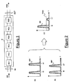
- FIG. 1 schematically shows a band-pass radio filter F.
- the band-pass radio filter F comprises six cascaded resonant cavities RC1, RC2, ..., RC6. This is merely exemplary, since the band-pass radio filter F may include any number of resonant cavities.
- the band-pass radio filter F has an input IN connected to the first resonant cavity RC1 and an output OUT connected to the last resonant cavity RC6.
- the input IN is suitable to receive a radio signal RS and to forward it to the cascade of the six resonant cavities RC1, RC2, ..., RC6, which perform a band-pass filtering operation upon it.
- the output OUT is suitable to receive the filtered radio signal FRS from the cascade of the six resonant cavities RC1, RC2, ..., RC6 and to output it towards a further radio component (not shown in Figure 1 ).
- the resonant cavities RC1, RC2, ..., RC6 have respective spectral responses.
- the spectral responses of all the resonant cavities RC1, RC2, ..., RC6 have a same fundamental resonance frequency f0.
- the overall spectral response of the filter F which is calculated as the product of the spectral responses of the six resonant cavities RC1, RC2, ..., RC6, is a band-pass spectral response with a passing band centred at the fundamental resonance frequency f0.
- At least one of the six resonant cavities RC1, RC2, ..., RC6 is of a type different from the other resonant cavities of the band-pass radio filter F.
- the first resonant cavity RC1 and the last resonant cavity RC6 are of a type different from the other resonant cavities RC2, RC3, RC4 and RC5.
- the resonant cavities RC2, RC3, RC4 and RC5 may be waveguide resonant cavities, while the resonant cavities RC1 and RC6 may be coaxial resonant cavities.
- the resonant cavities RC1 and RC6 are identical the one to the other, thus having a same first spectral response.
- the resonant cavities RC1 and RC6 are coaxial resonant cavities, they may have the same shape, size and length (i.e. ⁇ 0/4, ⁇ 0 being the wavelength corresponding to the fundamental resonance frequency f0).
- the resonant cavities RC2, RC3, RC4 and RC5 are identical the one to the other, thus having a same second spectral response.
- the resonant cavities RC2, RC3, RC4 and RC5 are waveguide resonant cavities, they may be waveguide stubs of a same conductive material, having a same cross-section (e.g. a rectangular cross-section) and a same length (i.e. ⁇ 0/2, ⁇ 0 being the wavelength corresponding to the fundamental resonance frequency f0).
- graph (a) shows the first spectral response (i.e. the power transmission coefficient versus frequency) SR' of the resonant cavities RC1 and RC6
- graph (b) shows the second spectral response (i.e. the power transmission coefficient versus frequency) SR" of the resonant cavities RC2, RC3, RC4 and RC5.
- the graphs (a) and (b) are not in scale.
- graph (c) is not in scale.
- Graph (c) shows that the overall spectral response SR of the band-pass radio filter F has a main passing band centred at the fundamental resonance frequency f0 and a spurious passing band centred at the first order resonance frequency f1" of the second spectral response SR".
- the power transmission coefficient within the spurious passing band is remarkably lower than the power transmission coefficient that would result for a band-pass radio filter comprising resonant cavities all having a same first order resonance frequency.
- graphs (a) and (b) show that the power transmission coefficient of each resonant cavity within the spurious passing band is substantially equal to the power transmission coefficient of the resonant cavity within the main passing band
- graph (c) shows that the power transmission coefficient of the overall band-pass radio filter F within the spurious passing band is well below the power transmission coefficient of the overall band-pass radio filter F within the main passing band.
- an "intermediate" cavity (such as e.g. RC2, RC3, RC4 or RC5) may be of a type different from the other resonant cavities.
- the remarkable reduction of the power transmission coefficient within the spurious passing bands may allow to employ the band-pass radio filter F in a radio communication device.
- the band-pass filter is suitable to be employed in a radio communication device.
- the former can be further decreased to a value lower than the maximum power transmission coefficient by cascading a low-pass radio filter to the band-pass radio filter. Since, according to preferred embodiments of the present invention, the power transmission coefficient within the spurious transmission band is very low, this result can be achieved by using a low-pass radio filter of a very low order which therefore introduces very low additional insertion losses.
- the band-pass radio filter F may be manufactured in a very compact form and reduced in size, and it exhibits very low insertion losses.
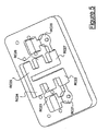
- Figure 3 shows a band-pass radio filter F1 according to another embodiment of the present invention.
- the band-pass radio filter F1 comprises six cascaded resonant cavities RC11, RC12, ... RC16.
- the resonant cavities RC11 and RC16 are coaxial cavities, whereas the resonant cavities RC12, RC13, RC14 and RC15 are dielectric resonators.
- the resonant cavities RC11, RC12, ... RC16 are arranged according to an in-line configuration.
- the band-pass filter F1 has a first connector C1 and a second connector C2 which are configured for connecting the band-pass radio filter F to other radio components (not shown in Figure 3 ).
- Figure 4 is a graph showing the spectral response (i.e. the power transmission coefficient versus frequency) of the band-pass filter F1.
- the graph of Figure 4 has been obtained by means of a numerical simulation based on the FEM calculation method (Finite Element Method).
- Figure 4 shows that the band-pass filter F1 has a main passing band centred at a fundamental resonance frequency f01 equal to about 5.914 GHz and a spurious passing band centred at a first order resonant frequency f11 equal to about 6.646 GHz.
- the spectral response of the band-pass filter F1 within the main passing band has a power transmission coefficient of about -0.1 dB. Accordingly, advantageously, within the passing band the filter F1 exhibits very low insertion losses, i.e. a radio signal filtered by the filter F1 undergoes a very low attenuation.
- the spectral response has a power transmission coefficient substantially lower than or equal to -50dB.
- the spectral response has a power transmission coefficient of about -50 dBm. Therefore, advantageously, the power transmission coefficient of the filter F1 within the spurious passing band is lower than the maximum power transmission coefficient -50 dB established for telecommunication applications. Accordingly, the filter F1 is suitable for being included in a radio communication device.
- Figure 5 shows a band-pass radio filter F2 according to a further embodiment of the present invention.
- the band-pass radio filter F2 comprises eight cascaded resonant cavities RC21, RC22, ..., RC82.
- the resonant cavities RC21 and RC28 are coaxial cavities
- the resonant cavities RC22, RC23, RC24, RC25, RC26 and RC27 are waveguide resonant cavities, i.e. they are waveguide stubs with a length of ⁇ 0 /2.
- the resonant cavities RC21, RC22, ..., RC82 are arranged according to a "U" structure.
- Figure 6 is a graph showing the spectral response (i.e. the power transmission coefficient versus frequency) of the band-pass filter F2.
- the graph of Figure 6 has been derived by experimentally measuring the spectral response of the filter F2 by means of an electrical spectrum analyser.
- Figure 6 shows that the band-pass filter F2 has a main passing band centred at a fundamental resonance frequency f02 equal to about 7.527 GHz and a spurious passing band centred at a first order resonant frequency f12 equal to about 17.535 GHz.
- the spectral response of the band-pass filter F2 within the main passing band has a power transmission coefficient of about -1.9 dB. Accordingly, advantageously, within the passing band the filter F2 exhibits very low insertion losses, i.e. a radio signal filtered by the filter F2 undergoes a very low attenuation.
- the spectral response has a power transmission coefficient substantially lower than or equal to -50dB.
- the spectral response has a power transmission coefficient of about -53 dBm. Therefore, advantageously, the power transmission coefficient of the filter F2 within the spurious passing band is lower than the maximum power transmission coefficient -50 dB established for telecommunication application. Accordingly, the filter F2 is suitable for being included in a radio communication device.
Landscapes
- Physics & Mathematics (AREA)
- Electromagnetism (AREA)
- Control Of Motors That Do Not Use Commutators (AREA)
Description
- The present invention generally relates to the field of radio communication devices. In particular, the present invention relates to a band-pass radio filter.
- In a radio communication network, information is transported in form of radio signals, each radio signal being an electromagnetic wave whose carrier frequency is comprised in the range of radio frequencies or in the range of microwave frequencies, according to the features of the radio communication system (system capacity, span length, etc.).
- An apparatus of a radio communication system typically comprises an antenna configured to transmit and/or receive radio signals and one or more radio communication devices configured to process the transmitting radio signals and/or the received radio signals.
- An exemplary radio communication device is a multiplexer, which allows to multiplex a plurality of radio signals having different carrier frequencies into a single multi-carrier radio signal to be transmitted by means of the antenna. A further exemplary radio communication device is a demultiplexer, which allows to demultiplex a multi-carrier radio signal received by means of the antenna into a plurality of radio signals having different carrier frequencies,
- A radio communication device typically comprises a combination of different radio components, such as radio filters (either band-pass, low-pass or high-pass), diplexers, circulators, delay lines and so on.
- In particular, band-pass radio filters may be implemented according to two known techniques.
- According to a first known technique, a band-pass radio filter is obtained by cascading a low-pass radio filter and a high-pass radio filter. If the cut-off frequency of the low-pass radio filter is higher than the cut-off frequency of the high-pass radio filter, the cascade of the two radio filters has an overall band-pass spectral response, whose bandwidth is equal to the difference between the cut-off frequency of the low-pass radio filter and the cut-off frequency of the high-pass radio filter.
- According to a second known technique, a band-pass radio filter is obtained by cascading a number of resonant cavities. If all the resonant cavities have a same fundamental resonance frequency, the cascade of the resonant cavities has an overall band-pass spectral response, whose passing band is substantially centered at the fundamental resonance frequency of the resonant cavities, and whose bandwidth is dependent on the spectral response of each single resonant cavity, on the coupling intensity between adjacent resonant cavities and on the overall number of cascaded resonant cavities. In the following description, a band-pass radio filter based on this second technique will be termed "resonant cavity filter".
- Different types of resonant cavity filters are known in the art, according to the type of resonant cavities they include.
- A first type of resonant cavity filter is represented by the coaxial filters. A coaxial filter may include a number of cascaded coaxial resonant cavities, each coaxial resonant cavity having a length of about λ/4, λ being the wavelength corresponding to the fundamental resonance frequency of the coaxial resonant cavity. Adjacent coaxial resonant cavities are coupled to each other according to an alternated configuration. Alternatively, a coaxial filter may include a number of cascaded coaxial resonant cavities, each coaxial resonant cavity having a length of about λ/8, wherein adjacent coaxial resonant cavities are coupled each other according to a "combline" configuration.
- A second type of resonant cavity filter is represented by the waveguide filters. A waveguide filter typically comprises a number of cascaded waveguide resonant cavities, each waveguide resonant cavity comprising a waveguide stub (e.g. a rectangular waveguide stub) having a length of λ/2, λ being the wavelength corresponding to the fundamental resonance frequency of the waveguide resonant cavity. Adjacent waveguide resonant cavities are typically coupled to each other by means of an iris, whose shape and size determines the coupling intensity between the adjacent waveguide resonant cavities.
- A third type of resonant cavity filter is represented by the dielectric resonator filters. Typically, a dielectric resonator filter comprises a cascade of a number of dielectric resonators which are placed within a waveguide. Typically, the waveguide is configured so that propagation of the fundamental mode (i.e. TE10) is prevented. The longitudinal distance between consecutive dielectric resonators within the waveguide determines the coupling intensity between consecutive dielectric resonators.
- Documents
EP A2 827233 EP A1 1148575 describe pass band filters with resonators of the same type, where some of the resonators have different higher order resonant frequencies. DocumentWO 99/01905 - The above band-pass radio filters have some drawbacks.
- Indeed, as to the band-pass radio filters implemented according to the above first technique (i.e. cascading a low-pass radio filter and a high-pass radio filter), they are costly and they have rather high weight and size. Further, disadvantageously, they exhibit rather high insertion losses within the passing band, thus inducing high attenuations on filtered radio signals.
- As to the resonant cavity filters, their spectral response disadvantageously exhibits, in addition to the passing band centered at the fundamental resonance frequency of the resonant cavities (which, in the present description, will be termed "main passing band"), further passing bands (which in the present description will be termed "spurious passing bands") centered at the resonance frequencies of higher orders of the resonant cavities. Disadvantageously, such spurious passing bands may make the resonant cavity filter not suitable for applications in radio communication devices.
- Indeed, generally, a band-pass radio filter for a radio communication device should have, within the main passing band, a power transmission coefficient (i.e. the ratio between the power exiting the filter and the power entering the filter) higher than a predetermined minimum power transmission coefficient and, externally to the main passing band, a power transmission coefficient lower than a predetermined maximum power transmission coefficient (which is typically -50 dB).
- If the power transmission coefficient of a resonant cavity filter within at least one of the spurious passing bands is higher than the maximum power transmission coefficient, the second requirement is not fulfilled, and therefore the resonant cavity filter can not be included in a radio communication device.
- Accordingly, the main object of the present invention is providing a band-pass radio filter which overcomes the aforesaid drawbacks.
- In particular, an object of the present invention is providing a band-pass radio filter which is less costly and which has lower weight and size than known band-pass radio filters while exhibiting, externally to the main passing band, a power transmission coefficient lower than the maximum power transmission coefficient which is typically required for radio communication applications.
- According to an aspect thereof, the present invention provides a pass-band radio filter including a number of resonant cavities, wherein each of the number of resonant cavities has a fundamental resonance frequency, characterized in that at least one of the number of resonant cavities is of a first type of resonant cavity and has a first higher order resonance frequency and in that remaining resonant cavities of the number of resonant cavities are of a second type of resonant cavity and have a second higher order resonance frequency, the second higher order resonance frequency being different from the first higher order resonance frequency, said first type being different from said second type, and said type and said second type being selected among: waveguide resonant cavity, coaxial resonant cavity and dielectric resonators.
- Preferably, the number of resonant cavities are arranged in cascade and the at least one of the number of resonant cavities includes a first resonant cavity in the cascade arrangement, which is suitable to receive a radio signal to be filtered, and a last resonant cavity in the cascade arrangement, which is suitable to emit said radio signal after filtering.
- Preferably, the number of resonant cavities consists in six or eight cascaded resonant cavities.
- Preferably, the first resonant cavity and the last resonant cavity are coaxial cavities.
- Preferably, a remaining number of resonant cavities, other than the first resonant cavity and the last resonant cavity, are waveguide resonant cavities or dielectric resonators.
- Preferably, the number of resonant cavities are arranged according to an in-line configuration or according to a U structure.
- Profitably, the band-pass radio filter further comprises a low-pass filter cascaded to said number of resonant cavities.
- The present invention will become clearer by the following detailed description, given by way of example and not of limitation, to be read with reference to the accompanying drawings, wherein:
-
Figure 1 schematically shows an exemplary embodiment of a band-pass radio filter including six resonant cavities suitable for the implementation of the present invention; -
Figure 2 schematically shows the spectral response of some of the resonant cavities ofFigure 1 (graphs (a) and (b)) and the overall spectral response of the band-pass radio filter ofFigure 1 (graph (c)); -
Figure 3 shows a band-pass radio filter according to another embodiment of the present invention; -
Figure 4 shows the spectral response of the band-pass radio filter ofFigure 3 , obtained by numerical simulation; -
Figure 5 shows a band-pass radio filter according to a further embodiment of the present invention; and -
Figure 6 shows spectral response of the band-pass radio filter ofFigure 5 , obtained by experimental measurement. -
Figure 1 schematically shows a band-pass radio filter F. The band-pass radio filter F comprises six cascaded resonant cavities RC1, RC2, ..., RC6. This is merely exemplary, since the band-pass radio filter F may include any number of resonant cavities. - Further, the band-pass radio filter F has an input IN connected to the first resonant cavity RC1 and an output OUT connected to the last resonant cavity RC6. The input IN is suitable to receive a radio signal RS and to forward it to the cascade of the six resonant cavities RC1, RC2, ..., RC6, which perform a band-pass filtering operation upon it. The output OUT is suitable to receive the filtered radio signal FRS from the cascade of the six resonant cavities RC1, RC2, ..., RC6 and to output it towards a further radio component (not shown in
Figure 1 ). - Preferably, the resonant cavities RC1, RC2, ..., RC6 have respective spectral responses. Preferably, the spectral responses of all the resonant cavities RC1, RC2, ..., RC6 have a same fundamental resonance frequency f0. Accordingly, the overall spectral response of the filter F, which is calculated as the product of the spectral responses of the six resonant cavities RC1, RC2, ..., RC6, is a band-pass spectral response with a passing band centred at the fundamental resonance frequency f0.
- According to preferred embodiments of the present invention, at least one of the six resonant cavities RC1, RC2, ..., RC6 is of a type different from the other resonant cavities of the band-pass radio filter F.
- By way of example, in the following description of
Figure 1 , it will be assumed that the first resonant cavity RC1 and the last resonant cavity RC6 are of a type different from the other resonant cavities RC2, RC3, RC4 and RC5. This is merely exemplary, as it will be discussed in further detail herein after. For instance, the resonant cavities RC2, RC3, RC4 and RC5 may be waveguide resonant cavities, while the resonant cavities RC1 and RC6 may be coaxial resonant cavities. - Preferably, the resonant cavities RC1 and RC6 are identical the one to the other, thus having a same first spectral response. For instance, in case the resonant cavities RC1 and RC6 are coaxial resonant cavities, they may have the same shape, size and length (i.e. λ0/4, λ0 being the wavelength corresponding to the fundamental resonance frequency f0). Further, preferably, the resonant cavities RC2, RC3, RC4 and RC5 are identical the one to the other, thus having a same second spectral response. For instance, in case the resonant cavities RC2, RC3, RC4 and RC5 are waveguide resonant cavities, they may be waveguide stubs of a same conductive material, having a same cross-section (e.g. a rectangular cross-section) and a same length (i.e. λ0/2, λ0 being the wavelength corresponding to the fundamental resonance frequency f0).
- By referring now to
Figure 2 , graph (a) shows the first spectral response (i.e. the power transmission coefficient versus frequency) SR' of the resonant cavities RC1 and RC6, whereas graph (b) shows the second spectral response (i.e. the power transmission coefficient versus frequency) SR" of the resonant cavities RC2, RC3, RC4 and RC5. The graphs (a) and (b) are not in scale. - The comparison between graph (a) and graph (b) shows that, even though both the spectral responses SR' and SR" have the same fundamental resonance frequency f0, the first spectral response SR' of the resonant cavities RC1 and RC6 exhibits a first order resonance frequency f1', while the second spectral response SR" of the resonance cavities SR" has a first order resonance frequency f1' different from f1'. This is due to the fact that the resonant cavities RC1 and RC6 are of a type different from the resonant cavities RC2, RC3, RC4 and RC5.
- Although the graphs (a) and (b) only show the first order resonance frequencies f1' and f1", respectively, the above considerations also apply to the higher order resonance frequencies, which for simplicity are not shown in the graphs of
Figure 2 . - Graph (c) of
Figure 2 shows the overall spectral response (i.e. the power transmission coefficient versus frequency) SR of the band-pass radio filter F, which is obtained by multiplying the spectral responses of the resonant cavities RC1, RC2, ..., RC6, i.e.:
- Also graph (c) is not in scale. Graph (c) shows that the overall spectral response SR of the band-pass radio filter F has a main passing band centred at the fundamental resonance frequency f0 and a spurious passing band centred at the first order resonance frequency f1" of the second spectral response SR".
- However, thanks to the fact that not all the resonant cavities have a same first order resonance frequency (i.e. not all the resonant cavities are of a same type), the power transmission coefficient within the spurious passing band is remarkably lower than the power transmission coefficient that would result for a band-pass radio filter comprising resonant cavities all having a same first order resonance frequency.
- Indeed, while graphs (a) and (b) show that the power transmission coefficient of each resonant cavity within the spurious passing band is substantially equal to the power transmission coefficient of the resonant cavity within the main passing band, graph (c) shows that the power transmission coefficient of the overall band-pass radio filter F within the spurious passing band is well below the power transmission coefficient of the overall band-pass radio filter F within the main passing band.
- Although the above considerations are referred to the embodiment of
Figures 1 and 2 , wherein it has been assumed that the resonant cavities RC1 and RC6 are of a type different from the resonant cavities RC2, RC3, RC4 and RC5, numerical simulations have shown that the same result (i.e. remarkable reduction of the power transmission coefficient within the spurious passing bands) is obtained each time at least one of the resonant cavities is of a type different from the other resonant cavities of the filter (i.e. it has higher order resonance frequencies different from the higher order resonance frequencies of the other resonant cavities), independently of the position of such at least one resonant cavity within the filter. Indeed, even if in the above description it has been assumed that the first and last resonant cavities RC1 and RC6 are of a type different from the "intermediate" resonant cavities RC2, RC3, RC4 and RC5, according to other embodiments (not shown in the drawings) of the present invention, an "intermediate" cavity (such as e.g. RC2, RC3, RC4 or RC5) may be of a type different from the other resonant cavities. - The remarkable reduction of the power transmission coefficient within the spurious passing bands may allow to employ the band-pass radio filter F in a radio communication device.
- Indeed, advantageously, if the power transmission coefficient within the spurious passing band is lower than the maximum power transmission coefficient defined in the introduction of the present description, the band-pass filter is suitable to be employed in a radio communication device.
- Anyway, even if the power transmission coefficient within the spurious passing band is higher than the maximum power transmission coefficient, the former can be further decreased to a value lower than the maximum power transmission coefficient by cascading a low-pass radio filter to the band-pass radio filter. Since, according to preferred embodiments of the present invention, the power transmission coefficient within the spurious transmission band is very low, this result can be achieved by using a low-pass radio filter of a very low order which therefore introduces very low additional insertion losses.
- Further, advantageously, the band-pass radio filter F may be manufactured in a very compact form and reduced in size, and it exhibits very low insertion losses.
-
Figure 3 shows a band-pass radio filter F1 according to another embodiment of the present invention. - The band-pass radio filter F1 comprises six cascaded resonant cavities RC11, RC12, ... RC16. Preferably, the resonant cavities RC11 and RC16 are coaxial cavities, whereas the resonant cavities RC12, RC13, RC14 and RC15 are dielectric resonators. The resonant cavities RC11, RC12, ... RC16 are arranged according to an in-line configuration. Further, the band-pass filter F1 has a first connector C1 and a second connector C2 which are configured for connecting the band-pass radio filter F to other radio components (not shown in
Figure 3 ). -
Figure 4 is a graph showing the spectral response (i.e. the power transmission coefficient versus frequency) of the band-pass filter F1. The graph ofFigure 4 has been obtained by means of a numerical simulation based on the FEM calculation method (Finite Element Method). -
Figure 4 shows that the band-pass filter F1 has a main passing band centred at a fundamental resonance frequency f01 equal to about 5.914 GHz and a spurious passing band centred at a first order resonant frequency f11 equal to about 6.646 GHz. - The spectral response of the band-pass filter F1 within the main passing band has a power transmission coefficient of about -0.1 dB. Accordingly, advantageously, within the passing band the filter F1 exhibits very low insertion losses, i.e. a radio signal filtered by the filter F1 undergoes a very low attenuation.
- On the other hand, externally to the main passing band, the spectral response has a power transmission coefficient substantially lower than or equal to -50dB. In particular, within the spurious passing band centred at f11, the spectral response has a power transmission coefficient of about -50 dBm. Therefore, advantageously, the power transmission coefficient of the filter F1 within the spurious passing band is lower than the maximum power transmission coefficient -50 dB established for telecommunication applications. Accordingly, the filter F1 is suitable for being included in a radio communication device.
-
Figure 5 shows a band-pass radio filter F2 according to a further embodiment of the present invention. - The band-pass radio filter F2 comprises eight cascaded resonant cavities RC21, RC22, ..., RC82. Preferably, the resonant cavities RC21 and RC28 are coaxial cavities, whereas the resonant cavities RC22, RC23, RC24, RC25, RC26 and RC27 are waveguide resonant cavities, i.e. they are waveguide stubs with a length of λ0/2. The resonant cavities RC21, RC22, ..., RC82 are arranged according to a "U" structure.
-
Figure 6 is a graph showing the spectral response (i.e. the power transmission coefficient versus frequency) of the band-pass filter F2. The graph ofFigure 6 has been derived by experimentally measuring the spectral response of the filter F2 by means of an electrical spectrum analyser. -
Figure 6 shows that the band-pass filter F2 has a main passing band centred at a fundamental resonance frequency f02 equal to about 7.527 GHz and a spurious passing band centred at a first order resonant frequency f12 equal to about 17.535 GHz. - The spectral response of the band-pass filter F2 within the main passing band has a power transmission coefficient of about -1.9 dB. Accordingly, advantageously, within the passing band the filter F2 exhibits very low insertion losses, i.e. a radio signal filtered by the filter F2 undergoes a very low attenuation.
- On the other hand, externally to the main passing band, the spectral response has a power transmission coefficient substantially lower than or equal to -50dB. In particular, within the spurious passing band centred at f12, the spectral response has a power transmission coefficient of about -53 dBm. Therefore, advantageously, the power transmission coefficient of the filter F2 within the spurious passing band is lower than the maximum power transmission coefficient -50 dB established for telecommunication application. Accordingly, the filter F2 is suitable for being included in a radio communication device.
Claims (10)
- Pass-band radio filter (F) including a number of resonant cavities (RC1, RC2 ... RC6), wherein each of said number of resonant cavities (RC1, RC2 ... RC6) has a fundamental resonance frequency (f0), characterized in that at least one (RC1, RC6) of said number of resonant cavities (RC1, RC2 ... RC6) is of a first type of resonant cavity and has a first higher order resonance frequency (f1'), in that remaining resonant cavities (RC2, RC3, RC4, RC5) of said number of resonant cavities (RC1, RC2 ... RC6) are of a second type of resonant cavity and have a second higher order resonance frequency (f1"), said first type being different from said second type so that said second higher order resonance frequency (f1") is different from said first higher order resonance frequency (f1'), and in that said first type and said second type are selected among: waveguide resonant cavity, coaxial resonant cavity and dielectric resonator.
- The pass-band radio filter (F) according to claim 1, wherein said number of resonant cavities (RC1, RC2 ... RC6) are arranged in cascade and wherein said at least one (RC1, RC6) of said number of resonant cavities (RC1, RC2 ..., RC6) includes a first resonant cavity (RC1) in said cascade arrangement, which is suitable to receive a radio signal to be filtered (RS), and a last resonant cavity (RC6) in said cascade arrangement, which is suitable to emit said radio signal after filtering (FRS).
- The pass-band radio filter (F) according to claim 1 or 2, wherein said number of resonant cavities (RC1, RC2 ... RC6) consists in six cascaded resonant cavities (RC11, RC12 ... RC16).
- The pass-band radio filter (F) according to claim 1 or 2, wherein said number of resonant cavities (RC1, RC2 ... RC6) consists in eight cascaded resonant cavities (RC21, RC22 ... RC28).
- The pass-band radio filter (F) according to any one of the claims 2 to 4 , wherein said first resonant cavity (RG1) and said last resonant cavity (RC6) are coaxial cavities.
- The band-pass radio filter (F) according to any one of claims 2 to 5, wherein a remaining number of resonant cavities (RC2, RC3, RC4, RC5), other than the first resonant cavity and the last resonant cavity, are waveguide resonant cavities.
- The band-pass radio filter (F) according to any one of claims 2 to 5, wherein a remaining number of resonant cavities (RC2, RC3, RC4, RC5), other than the first resonant cavity and the last resonant cavity, are dielectric resonators.
- The band-pass radio filter (F) according to any of the preceding claims, wherein said number of resonant cavities (RC1, RC2 ... RC6) are arranged according to an in-line configuration.
- The band-pass radio filter (F) according to any of the claims 1 to 8, wherein said number of resonant cavities (RC1, RC2 ... RC6) are arranged according to a U structure.
- The band-pass radio filter (F) according to any of the preceding claims, wherein it further comprises a low-pass filter cascaded to said number of resonant cavities (RC1, RC2 ... RC6).
Priority Applications (1)
| Application Number | Priority Date | Filing Date | Title |
|---|---|---|---|
| EP20070291436 EP2065967B1 (en) | 2007-11-30 | 2007-11-30 | Bandpass filter |
Applications Claiming Priority (1)
| Application Number | Priority Date | Filing Date | Title |
|---|---|---|---|
| EP20070291436 EP2065967B1 (en) | 2007-11-30 | 2007-11-30 | Bandpass filter |
Publications (2)
| Publication Number | Publication Date |
|---|---|
| EP2065967A1 EP2065967A1 (en) | 2009-06-03 |
| EP2065967B1 true EP2065967B1 (en) | 2014-06-04 |
Family
ID=39171414
Family Applications (1)
| Application Number | Title | Priority Date | Filing Date |
|---|---|---|---|
| EP20070291436 Active EP2065967B1 (en) | 2007-11-30 | 2007-11-30 | Bandpass filter |
Country Status (1)
| Country | Link |
|---|---|
| EP (1) | EP2065967B1 (en) |
Families Citing this family (1)
| Publication number | Priority date | Publication date | Assignee | Title |
|---|---|---|---|---|
| CN110444845B (en) * | 2019-07-25 | 2024-01-26 | 华南理工大学 | Coaxial cavity duplexer |
Family Cites Families (5)
| Publication number | Priority date | Publication date | Assignee | Title |
|---|---|---|---|---|
| JP2910807B2 (en) * | 1991-10-25 | 1999-06-23 | 株式会社村田製作所 | Dielectric resonator device, dielectric filter, and method of manufacturing the same |
| JP3085205B2 (en) * | 1996-08-29 | 2000-09-04 | 株式会社村田製作所 | TM mode dielectric resonator, TM mode dielectric filter and TM mode dielectric duplexer using the same |
| US5969584A (en) * | 1997-07-02 | 1999-10-19 | Adc Solitra Inc. | Resonating structure providing notch and bandpass filtering |
| EP1148575A4 (en) * | 1999-11-02 | 2003-04-09 | Matsushita Electric Ind Co Ltd | Dielectric filter |
| JP3780417B2 (en) * | 2002-02-12 | 2006-05-31 | 株式会社村田製作所 | Dielectric resonator, dielectric filter, dielectric duplexer, and communication device |
-
2007
- 2007-11-30 EP EP20070291436 patent/EP2065967B1/en active Active
Also Published As
| Publication number | Publication date |
|---|---|
| EP2065967A1 (en) | 2009-06-03 |
Similar Documents
| Publication | Publication Date | Title |
|---|---|---|
| CA2338500A1 (en) | A tunable microwave multiplexer | |
| EP2049929B1 (en) | Ultra-narrow bandpass filter | |
| US8008990B2 (en) | Generalized multiplexing network | |
| US5254963A (en) | Microwave filter with a wide spurious-free band-stop response | |
| EP2065967B1 (en) | Bandpass filter | |
| Zhu et al. | A compact waveguide quasi-elliptic dual-band filter | |
| EP2077600A1 (en) | Cavity filter coupling system | |
| EP1575119A1 (en) | Superconductive microstrip resonator and filter | |
| EP1508935A1 (en) | Band pass filter | |
| Lin et al. | High-isolation diplexer on triple-mode cavity filters | |
| WO2017042560A1 (en) | A microwave switched multiplexer and a mobile telecommunications device including such a multiplexer | |
| EP2559098B1 (en) | Multi-band filter | |
| Hauth et al. | The corrugated-waveguide sand-pass filter-a new type of waveguide filter | |
| RU81002U1 (en) | DIPLEXER | |
| Rubin et al. | Millimeter wave MIC bandpass filters and multiplexers | |
| Breuer et al. | A low cost multiplexer for channelized receiver front ends at millimeter waves | |
| CA1081808A (en) | Dual mode self-equalized bandpass filters | |
| Setti et al. | Ku Band Waveguide Diplexer for Satellite Communication Links | |
| Mohammadi et al. | A sharp‐selective micro strip triplexer with hairpin resonators for long‐term evolution (LTE) | |
| Abdelmonem et al. | Full-wave design of spurious free DR TE mode band pass filters | |
| RU2150770C1 (en) | Multiplexer | |
| Xiong et al. | Using intrinsic zero to notch satellite signals in UWB filter | |
| RU2399997C1 (en) | Rejector waveguide multilink microwave filter | |
| RU2295807C1 (en) | Diplexer | |
| WO2000022692A1 (en) | Microwave filter |
Legal Events
| Date | Code | Title | Description |
|---|---|---|---|
| PUAI | Public reference made under article 153(3) epc to a published international application that has entered the european phase |
Free format text: ORIGINAL CODE: 0009012 |
|
| AK | Designated contracting states |
Kind code of ref document: A1 Designated state(s): AT BE BG CH CY CZ DE DK EE ES FI FR GB GR HU IE IS IT LI LT LU LV MC MT NL PL PT RO SE SI SK TR |
|
| AX | Request for extension of the european patent |
Extension state: AL BA HR MK RS |
|
| 17P | Request for examination filed |
Effective date: 20091203 |
|
| 17Q | First examination report despatched |
Effective date: 20100108 |
|
| AKX | Designation fees paid |
Designated state(s): AT BE BG CH CY CZ DE DK EE ES FI FR GB GR HU IE IS IT LI LT LU LV MC MT NL PL PT RO SE SI SK TR |
|
| RAP1 | Party data changed (applicant data changed or rights of an application transferred) |
Owner name: ALCATEL LUCENT |
|
| 111Z | Information provided on other rights and legal means of execution |
Free format text: AT BE BG CH CY CZ DE DK EE ES FI FR GB GR HU IE IS IT LI LT LU LV MC MT NL PL PT RO SE SI SK TR Effective date: 20130410 |
|
| GRAP | Despatch of communication of intention to grant a patent |
Free format text: ORIGINAL CODE: EPIDOSNIGR1 |
|
| INTG | Intention to grant announced |
Effective date: 20131218 |
|
| GRAS | Grant fee paid |
Free format text: ORIGINAL CODE: EPIDOSNIGR3 |
|
| GRAA | (expected) grant |
Free format text: ORIGINAL CODE: 0009210 |
|
| AK | Designated contracting states |
Kind code of ref document: B1 Designated state(s): AT BE BG CH CY CZ DE DK EE ES FI FR GB GR HU IE IS IT LI LT LU LV MC MT NL PL PT RO SE SI SK TR |
|
| REG | Reference to a national code |
Ref country code: GB Ref legal event code: FG4D |
|
| REG | Reference to a national code |
Ref country code: CH Ref legal event code: EP |
|
| REG | Reference to a national code |
Ref country code: AT Ref legal event code: REF Ref document number: 671548 Country of ref document: AT Kind code of ref document: T Effective date: 20140615 |
|
| REG | Reference to a national code |
Ref country code: IE Ref legal event code: FG4D |
|
| REG | Reference to a national code |
Ref country code: DE Ref legal event code: R096 Ref document number: 602007036976 Country of ref document: DE Effective date: 20140710 |
|
| REG | Reference to a national code |
Ref country code: CH Ref legal event code: PCOW Free format text: NEW ADDRESS: 148/152 ROUTE DE LA REINE, 92100 BOULOGNE-BILLANCOURT (FR) |
|
| RAP2 | Party data changed (patent owner data changed or rights of a patent transferred) |
Owner name: ALCATEL LUCENT |
|
| REG | Reference to a national code |
Ref country code: AT Ref legal event code: MK05 Ref document number: 671548 Country of ref document: AT Kind code of ref document: T Effective date: 20140604 |
|
| REG | Reference to a national code |
Ref country code: NL Ref legal event code: VDEP Effective date: 20140604 |
|
| PG25 | Lapsed in a contracting state [announced via postgrant information from national office to epo] |
Ref country code: LT Free format text: LAPSE BECAUSE OF FAILURE TO SUBMIT A TRANSLATION OF THE DESCRIPTION OR TO PAY THE FEE WITHIN THE PRESCRIBED TIME-LIMIT Effective date: 20140604 Ref country code: FI Free format text: LAPSE BECAUSE OF FAILURE TO SUBMIT A TRANSLATION OF THE DESCRIPTION OR TO PAY THE FEE WITHIN THE PRESCRIBED TIME-LIMIT Effective date: 20140604 Ref country code: GR Free format text: LAPSE BECAUSE OF FAILURE TO SUBMIT A TRANSLATION OF THE DESCRIPTION OR TO PAY THE FEE WITHIN THE PRESCRIBED TIME-LIMIT Effective date: 20140905 Ref country code: CY Free format text: LAPSE BECAUSE OF FAILURE TO SUBMIT A TRANSLATION OF THE DESCRIPTION OR TO PAY THE FEE WITHIN THE PRESCRIBED TIME-LIMIT Effective date: 20140604 |
|
| REG | Reference to a national code |
Ref country code: LT Ref legal event code: MG4D |
|
| PG25 | Lapsed in a contracting state [announced via postgrant information from national office to epo] |
Ref country code: LV Free format text: LAPSE BECAUSE OF FAILURE TO SUBMIT A TRANSLATION OF THE DESCRIPTION OR TO PAY THE FEE WITHIN THE PRESCRIBED TIME-LIMIT Effective date: 20140604 Ref country code: AT Free format text: LAPSE BECAUSE OF FAILURE TO SUBMIT A TRANSLATION OF THE DESCRIPTION OR TO PAY THE FEE WITHIN THE PRESCRIBED TIME-LIMIT Effective date: 20140604 Ref country code: SE Free format text: LAPSE BECAUSE OF FAILURE TO SUBMIT A TRANSLATION OF THE DESCRIPTION OR TO PAY THE FEE WITHIN THE PRESCRIBED TIME-LIMIT Effective date: 20140604 |
|
| PG25 | Lapsed in a contracting state [announced via postgrant information from national office to epo] |
Ref country code: CZ Free format text: LAPSE BECAUSE OF FAILURE TO SUBMIT A TRANSLATION OF THE DESCRIPTION OR TO PAY THE FEE WITHIN THE PRESCRIBED TIME-LIMIT Effective date: 20140604 Ref country code: PT Free format text: LAPSE BECAUSE OF FAILURE TO SUBMIT A TRANSLATION OF THE DESCRIPTION OR TO PAY THE FEE WITHIN THE PRESCRIBED TIME-LIMIT Effective date: 20141006 Ref country code: EE Free format text: LAPSE BECAUSE OF FAILURE TO SUBMIT A TRANSLATION OF THE DESCRIPTION OR TO PAY THE FEE WITHIN THE PRESCRIBED TIME-LIMIT Effective date: 20140604 Ref country code: RO Free format text: LAPSE BECAUSE OF FAILURE TO SUBMIT A TRANSLATION OF THE DESCRIPTION OR TO PAY THE FEE WITHIN THE PRESCRIBED TIME-LIMIT Effective date: 20140604 Ref country code: SK Free format text: LAPSE BECAUSE OF FAILURE TO SUBMIT A TRANSLATION OF THE DESCRIPTION OR TO PAY THE FEE WITHIN THE PRESCRIBED TIME-LIMIT Effective date: 20140604 Ref country code: ES Free format text: LAPSE BECAUSE OF FAILURE TO SUBMIT A TRANSLATION OF THE DESCRIPTION OR TO PAY THE FEE WITHIN THE PRESCRIBED TIME-LIMIT Effective date: 20140604 |
|
| PG25 | Lapsed in a contracting state [announced via postgrant information from national office to epo] |
Ref country code: NL Free format text: LAPSE BECAUSE OF FAILURE TO SUBMIT A TRANSLATION OF THE DESCRIPTION OR TO PAY THE FEE WITHIN THE PRESCRIBED TIME-LIMIT Effective date: 20140604 Ref country code: PL Free format text: LAPSE BECAUSE OF FAILURE TO SUBMIT A TRANSLATION OF THE DESCRIPTION OR TO PAY THE FEE WITHIN THE PRESCRIBED TIME-LIMIT Effective date: 20140604 Ref country code: IS Free format text: LAPSE BECAUSE OF FAILURE TO SUBMIT A TRANSLATION OF THE DESCRIPTION OR TO PAY THE FEE WITHIN THE PRESCRIBED TIME-LIMIT Effective date: 20141004 |
|
| REG | Reference to a national code |
Ref country code: DE Ref legal event code: R097 Ref document number: 602007036976 Country of ref document: DE |
|
| PLBE | No opposition filed within time limit |
Free format text: ORIGINAL CODE: 0009261 |
|
| STAA | Information on the status of an ep patent application or granted ep patent |
Free format text: STATUS: NO OPPOSITION FILED WITHIN TIME LIMIT |
|
| PG25 | Lapsed in a contracting state [announced via postgrant information from national office to epo] |
Ref country code: IT Free format text: LAPSE BECAUSE OF FAILURE TO SUBMIT A TRANSLATION OF THE DESCRIPTION OR TO PAY THE FEE WITHIN THE PRESCRIBED TIME-LIMIT Effective date: 20140604 Ref country code: DK Free format text: LAPSE BECAUSE OF FAILURE TO SUBMIT A TRANSLATION OF THE DESCRIPTION OR TO PAY THE FEE WITHIN THE PRESCRIBED TIME-LIMIT Effective date: 20140604 |
|
| 26N | No opposition filed |
Effective date: 20150305 |
|
| REG | Reference to a national code |
Ref country code: DE Ref legal event code: R097 Ref document number: 602007036976 Country of ref document: DE Effective date: 20150305 |
|
| PG25 | Lapsed in a contracting state [announced via postgrant information from national office to epo] |
Ref country code: MC Free format text: LAPSE BECAUSE OF FAILURE TO SUBMIT A TRANSLATION OF THE DESCRIPTION OR TO PAY THE FEE WITHIN THE PRESCRIBED TIME-LIMIT Effective date: 20140604 Ref country code: BE Free format text: LAPSE BECAUSE OF FAILURE TO SUBMIT A TRANSLATION OF THE DESCRIPTION OR TO PAY THE FEE WITHIN THE PRESCRIBED TIME-LIMIT Effective date: 20140604 Ref country code: LU Free format text: LAPSE BECAUSE OF FAILURE TO SUBMIT A TRANSLATION OF THE DESCRIPTION OR TO PAY THE FEE WITHIN THE PRESCRIBED TIME-LIMIT Effective date: 20141130 |
|
| REG | Reference to a national code |
Ref country code: CH Ref legal event code: PL |
|
| PG25 | Lapsed in a contracting state [announced via postgrant information from national office to epo] |
Ref country code: SI Free format text: LAPSE BECAUSE OF FAILURE TO SUBMIT A TRANSLATION OF THE DESCRIPTION OR TO PAY THE FEE WITHIN THE PRESCRIBED TIME-LIMIT Effective date: 20140604 Ref country code: LI Free format text: LAPSE BECAUSE OF NON-PAYMENT OF DUE FEES Effective date: 20141130 Ref country code: CH Free format text: LAPSE BECAUSE OF NON-PAYMENT OF DUE FEES Effective date: 20141130 |
|
| REG | Reference to a national code |
Ref country code: IE Ref legal event code: MM4A |
|
| PG25 | Lapsed in a contracting state [announced via postgrant information from national office to epo] |
Ref country code: IE Free format text: LAPSE BECAUSE OF NON-PAYMENT OF DUE FEES Effective date: 20141130 |
|
| REG | Reference to a national code |
Ref country code: FR Ref legal event code: PLFP Year of fee payment: 9 |
|
| PG25 | Lapsed in a contracting state [announced via postgrant information from national office to epo] |
Ref country code: BG Free format text: LAPSE BECAUSE OF FAILURE TO SUBMIT A TRANSLATION OF THE DESCRIPTION OR TO PAY THE FEE WITHIN THE PRESCRIBED TIME-LIMIT Effective date: 20140604 |
|
| PG25 | Lapsed in a contracting state [announced via postgrant information from national office to epo] |
Ref country code: TR Free format text: LAPSE BECAUSE OF FAILURE TO SUBMIT A TRANSLATION OF THE DESCRIPTION OR TO PAY THE FEE WITHIN THE PRESCRIBED TIME-LIMIT Effective date: 20140604 Ref country code: HU Free format text: LAPSE BECAUSE OF FAILURE TO SUBMIT A TRANSLATION OF THE DESCRIPTION OR TO PAY THE FEE WITHIN THE PRESCRIBED TIME-LIMIT; INVALID AB INITIO Effective date: 20071130 Ref country code: MT Free format text: LAPSE BECAUSE OF FAILURE TO SUBMIT A TRANSLATION OF THE DESCRIPTION OR TO PAY THE FEE WITHIN THE PRESCRIBED TIME-LIMIT Effective date: 20140604 |
|
| REG | Reference to a national code |
Ref country code: FR Ref legal event code: PLFP Year of fee payment: 10 |
|
| REG | Reference to a national code |
Ref country code: FR Ref legal event code: PLFP Year of fee payment: 11 |
|
| REG | Reference to a national code |
Ref country code: FR Ref legal event code: PLFP Year of fee payment: 12 |
|
| PGFP | Annual fee paid to national office [announced via postgrant information from national office to epo] |
Ref country code: FR Payment date: 20181011 Year of fee payment: 12 |
|
| PG25 | Lapsed in a contracting state [announced via postgrant information from national office to epo] |
Ref country code: FR Free format text: LAPSE BECAUSE OF NON-PAYMENT OF DUE FEES Effective date: 20191130 |
|
| PGFP | Annual fee paid to national office [announced via postgrant information from national office to epo] |
Ref country code: GB Payment date: 20231012 Year of fee payment: 17 |
|
| PGFP | Annual fee paid to national office [announced via postgrant information from national office to epo] |
Ref country code: DE Payment date: 20231003 Year of fee payment: 17 |