EP2065733A1 - Verfahren zur Korrektur magnetbasierter Ausrichtungsmessungen für lokale Vorspannungsfelder - Google Patents
Verfahren zur Korrektur magnetbasierter Ausrichtungsmessungen für lokale Vorspannungsfelder Download PDFInfo
- Publication number
- EP2065733A1 EP2065733A1 EP08169321A EP08169321A EP2065733A1 EP 2065733 A1 EP2065733 A1 EP 2065733A1 EP 08169321 A EP08169321 A EP 08169321A EP 08169321 A EP08169321 A EP 08169321A EP 2065733 A1 EP2065733 A1 EP 2065733A1
- Authority
- EP
- European Patent Office
- Prior art keywords
- data acquisition
- acquisition system
- horizontal magnetic
- seafloor
- magnetic fields
- Prior art date
- Legal status (The legal status is an assumption and is not a legal conclusion. Google has not performed a legal analysis and makes no representation as to the accuracy of the status listed.)
- Granted
Links
Images
Classifications
-
- G—PHYSICS
- G01—MEASURING; TESTING
- G01V—GEOPHYSICS; GRAVITATIONAL MEASUREMENTS; DETECTING MASSES OR OBJECTS; TAGS
- G01V3/00—Electric or magnetic prospecting or detecting; Measuring magnetic field characteristics of the earth, e.g. declination, deviation
- G01V3/12—Electric or magnetic prospecting or detecting; Measuring magnetic field characteristics of the earth, e.g. declination, deviation operating with electromagnetic waves
-
- G—PHYSICS
- G01—MEASURING; TESTING
- G01V—GEOPHYSICS; GRAVITATIONAL MEASUREMENTS; DETECTING MASSES OR OBJECTS; TAGS
- G01V3/00—Electric or magnetic prospecting or detecting; Measuring magnetic field characteristics of the earth, e.g. declination, deviation
- G01V3/08—Electric or magnetic prospecting or detecting; Measuring magnetic field characteristics of the earth, e.g. declination, deviation operating with magnetic or electric fields produced or modified by objects or geological structures or by detecting devices
- G01V3/083—Controlled source electromagnetic [CSEM] surveying
Definitions
- the invention relates generally to seafloor magnetic measurements, and, more particularly to a method and system for correcting magnetic based orientation measurements.
- the present invention is particularly related to remotely operable electromagnetic (EM) measurement systems, such as Magnetotelluric (MT) or controlled source electromagnetic (CSEM) measurement systems.
- EM remotely operable electromagnetic
- MT Magnetotelluric
- CSEM controlled source electromagnetic
- Both MT and CSEM use similar receiver setups. They differ in the sources of EM energies used in the surveys.
- MT uses natural EM perturbation induced in the formation.
- CSEM uses a controlled EM source that is towed by a ship, typically at about 50 feet from the seafloor, where the receiver arrays are placed. Because the receivers used for MT and CSEM share similar properties, the following description will focus on MT measurement. However, one of ordinary skill in the art will appreciate that the description is equally applicable to CSEM measurements, or other EM measurement techniques such as IP, TDEM or hybrid seismoelectric techniques.
- MT measurements are used to compute an EM impedance of selected earth formations.
- MT measurements are especially useful in regions where seismic imaging is inappropriate.
- MT exploration is useful when evaluating geologic formations such as salts and carbonates. Salts, carbonates, and other particular formations may scatter seismic energy when seismic energy is propagated through them because of large velocity contrasts and inhomogeneties located within these formations, whereas the EM energy of the MT source fields propagates through these layers with less distortion.
- MT methods measure variations in the earth's magnetic and electric fields, and do not rely on seismic energy to determine formation characteristics.
- MT methods may be used to measure an EM impedance as a function of frequency. Lower frequency provides a greater depth of penetration. The measured impedance may be transformed into an apparent resistivity and/or conductivity of the selected formations. Measuring impedance at several locations at various frequencies enables a determination of resistivity and/or conductivity as a function of both depth and horizontal position. Therefore, MT methods may be used to evaluate formation resistivity over large areas of the seafloor. The formation resistivities of the various formations in a selected area may then be analyzed to determine the formation geometry, the presence or absence of hydrocarbons in selected formations, and the like.
- MT methods are passive methods, in that MT methods use natural variations in the earth's magnetic field as an energy source. Such methods include a subsea system that detects orthogonal magnetic and electric fields proximate the seafloor to define a surface impedance.
- the surface impedance as described above, may be measured over a broad range of frequencies and over a large area where layered formations act in a manner analogous to segments of an electrical transmission line.
- One MT method that operates according to the principles described above is generally disclosed in U.S. Patent No. 5,770,945 issued to Constable.
- the type of EM receiver disclosed therein can also be used to record EM signals that originate from various kinds of transmitter systems, such as a towed cable bipole or magnetic loop source.
- the receivers could be used to detect EM radiation originating from other types of signals such as emanating from naval ships (corrosion currents, electric circuits, generators, moving machinery) or from electric or magnetic sources located in boreholes or nearly land sources.
- the objective of these measurements could range from detailed exploration of the subsurface conductivity structure to monitoring naval traffic or operations to determining leakage signals from subsea cables.
- a subsea system that may be used in MT methods includes an apparatus such as an MT measurement system 100 disclosed in the Constable patent.
- the MT measurement system 100 includes a body 102 having a battery pack (not shown), a data acquisition system 104, two orthogonally oriented magnetic sensors 122 and 124, and four arms 139, 140, 142, and 144, each of which includes an electrode 118, 119, 120, 121 mounted at the end thereof.
- the electrodes 118, 119, 120, 121 are silver-silver chloride electrodes, and the magnetic sensors 122, 124 are magnetic induction coil sensors.
- the arms 139, 140, 142, 144 are five meters long and approximately 2 inches in diameter.
- the arms 139, 140, 142, 144 may be formed from a semi-rigid plastic material (e.g., polyvinyl chloride or polypropylene) and are fixed to the body.
- the arms 139, 140, 142, 144 are designed to rest on the seafloor when the MT system 100 is deployed.
- the body 102 is attached to a releasable concrete anchor 128 that enables the MT system 100 sink to the seafloor after deployment.
- the body 102 generally rests on top of the anchor 128 when it is positioned on the seafloor.
- the anchor 128 may be released after MT measurements have been completed so that the body 102 may rise to the surface and be retrieved by a surface vessel (not shown).
- the three-dimensional (3D) orientation of the sensors is determined from independent measurements of the static magnetic field of the Earth H and measurements of the acceleration of gravity, g.
- An orientation measurement instrument uses a magneto-resistive device, fluxgate magnetometer, or DC magnetometer to measure the three components of the magnetic field and a three-component tilt meter to measure g. Alignment on the horizontal plane (heading) is obtained from the measure of the horizontal components of H, while the pitch and roll angles are obtained from measurements of g. Note the dip could alternatively be determined by directly reading a tiltmeter device such as a pendulum or electrolytic bubble tiltmeter.
- the measurement of the Earth's static magnetic field may be biased due to the presence of locally originated magnetic fields.
- Sources of locally originated magnetic fields may include induction sensors having highly permeable cores, remnant magnetic fields in the steel casing surrounding a battery, acoustic transducers, and fields arising from current flow within the electronics.
- the total magnetic field measurement is a superposition of the Earth's static magnetic field with the biasing fields arising from local sources.
- the effect of the biasing fields cannot be uniquely calibrated for a given data acquisition system because the biasing fields change with each deployment from modifications to the MT measurement system, including a new battery, induction sensors in a different position, or any other changes involving ferrous metal or electricity. Thus, calibration is required for each deployment of a MT measurement system.
- a compass needle floats on a solution that freezes at low temperatures. When the solution freezes, the compass needle is locked at the orientation of the sensors. Local magnetic sources can bias the compass reading. In some instances, the freezing point of the solution may not be reached at the seafloor, keeping the compass needle from being locked in place.
- Another related art calibration/orientation technique is data correlation with natural fields. Recorded EM data is correlated with data acquired at a reference site of known orientation. For example, the reference site may be on land. This technique is supported by the fact that plane wave natural fields are assumed homogeneous across both the land reference and seafloor deployments of the data acquisition system. Accuracy of the technique depends largely on data quality and may be unable to be used if one of the horizontal magnetic field measurements is missing, or distorted by subsurface structures.
- Another related art calibration/orientation technique is data correlation with controlled source fields.
- a transmitter antenna supplies a signal to be analyzed.
- the orientation of the transmitter antenna is assumed to be known, and then the data can be rotated to maximize the amplitude at the closest position of the transmitter.
- This technique relies on exact knowledge of the transmitter antenna position and orientation which change as a transmitter dipole is towed.
- the present disclosure relates to a method of determining an orientation of a data acquisition system deployed on a seafloor.
- the method includes measuring horizontal magnetic fields using detectors on the data acquisition system while the data acquisition system rotates and descends to or ascends from the seafloor, measuring resting horizontal magnetic fields while the data acquisition system is on the seafloor, and determining a heading of the data acquisition system on the seafloor based on calibration parameters determined during the descent, ascent or while the system rotates on the sea surface, and using these parameters to determine the undistorted horizontal magnetic field values, which are then used to determine the acquisition systems's orientation.
- the present disclosure relates to a data acquisition system that includes an orientation measurement instrument configured to measure a horizontal magnetic field and means for causing the rotation of the data acquisition system about a vertical axis during a descent to a seafloor or ascent from the seafloor, or while the system is rotating in the surface swell.
- FIG. 1 shows a prior art EM measurement system.
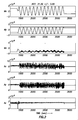
- FIG. 2 shows an example of data obtained during rotation of a data acquisition system.
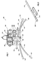
- FIG. 3 shows an example electrode mount for rotating a data acquisition system.
- a method for determining the orientation of an EM measurement system includes allowing the receiver to rotate about its vertical axis while measuring a horizontal magnetic field. The rotation of the receiver or data acquisition system may occur during a descent to the seafloor. The measurements taken during rotation may be used to determine a calibration parameter for the orientation measurement instrument.
- the calibration parameter(s) may be determined from an average maximum and/or minimum horizontal magnetic field measured during multiple rotations of the data acquisition system.
- FIG. 2 shows a sample record of measurements taken during the rotation of the data acquisition system.
- the data acquisition system is rotated during descent until landing on the seafloor at 1500 m depth while continuously performing measurements of the magnetic field.
- a full rotation of the data acquisition occurred about 125 seconds during the descent, as shown by the measurements of the horizontal magnetic field (Mx and My).
- Mx and My represents the corresponding magneto-resistive device pointing north.
- Mx and My represents the corresponding magneto-resistive device pointing south.
- the calibration parameters A, B are due to the intrinsic characteristics of the magneto-resistive device and the external bias imposed by the presence of magnetic field sources mounted on the data acquisition system.
- the calibration parameters can be indirectly determined and used to determine the magnetic field strength at a position on the seafloor from the following equations. Hx ⁇ 2 * Mx - ( Max - Min ⁇ ) x / ( Min - Max ⁇ ) x Hy ⁇ 2 * My - ( Max - Min ⁇ ) y / ( Min - Max ⁇ ) y
- the above equations are used to determine the heading angle ⁇ of the data acquisition system.
- the stable value following the periodic oscillation represents the end of the rotation of the data acquisition system, meaning that the data acquisition system has come to rest on the seafloor.
- FIG. 3 shows an example of an electrode mount 215 that can be used to impart a rotational force on the data acquisition system.
- the electrode 201 is attached to the dipole arm 210 extending from the data acquisition system.
- the electrode 201 is mounted near the free end 205 of the dipole arm 210.
- the electrode mount 215 may be angled on the dipole arm 210 with respect to the vertical axis of the data acquisition system.
- the electrode mount 215 may be mounted at a 45 degree angle, although in other examples, the electrode mount 215 may be mounted at a non-orthogonal angle and a least squares fitting may be applied to correct for any misalignment of the sensors- the angle of the mounting is secondary as long as after calibration, the acquisition system alignment can be determined.
- Electrode mounts on the other dipole arms may be similarly mounted such that each dipole arm imparts a rotational force in the same direction (clockwise or counterclockwise) as the data acquisition descends towards the seafloor. This same mounting would also suffice to impart an opposite sense rotation as the acquisition system was ascending from the sea floor.
- the size and angle of the electrode mounts and the length of the dipole arms will in large part determine the rotation speed of the data acquisition system during descent and ascent.
- the rotation speed may be about one rotation per minute.
- the invention is not limited to any particular rotation speed of the data acquisition system.
- the data acquisition system may be rotated during descent using a variety of techniques without departing from the scope of the invention.
- separate blades may be provided on the data acquisition system to act as a propeller.
- the dipole arms may be elliptical and oriented on the data acquisition system to function as a propeller.
Landscapes
- Physics & Mathematics (AREA)
- Engineering & Computer Science (AREA)
- Remote Sensing (AREA)
- Life Sciences & Earth Sciences (AREA)
- Electromagnetism (AREA)
- Environmental & Geological Engineering (AREA)
- Geology (AREA)
- General Life Sciences & Earth Sciences (AREA)
- General Physics & Mathematics (AREA)
- Geophysics (AREA)
- Geophysics And Detection Of Objects (AREA)
Applications Claiming Priority (1)
| Application Number | Priority Date | Filing Date | Title |
|---|---|---|---|
| US11/943,247 US7800373B2 (en) | 2007-11-20 | 2007-11-20 | Method for correcting magnetic based orientation measurements for local biasing fields |
Publications (2)
| Publication Number | Publication Date |
|---|---|
| EP2065733A1 true EP2065733A1 (de) | 2009-06-03 |
| EP2065733B1 EP2065733B1 (de) | 2012-02-22 |
Family
ID=40364986
Family Applications (1)
| Application Number | Title | Priority Date | Filing Date |
|---|---|---|---|
| EP08169321A Not-in-force EP2065733B1 (de) | 2007-11-20 | 2008-11-18 | Verfahren zur Korrektur magnetbasierter Ausrichtungsmessungen bei lokaler Feldüberlagerung |
Country Status (5)
| Country | Link |
|---|---|
| US (1) | US7800373B2 (de) |
| EP (1) | EP2065733B1 (de) |
| AU (1) | AU2008246227A1 (de) |
| BR (1) | BRPI0804981A2 (de) |
| MX (1) | MX2008014677A (de) |
Families Citing this family (4)
| Publication number | Priority date | Publication date | Assignee | Title |
|---|---|---|---|---|
| US20090265111A1 (en) * | 2008-04-16 | 2009-10-22 | Kjt Enterprises, Inc. | Signal processing method for marine electromagnetic signals |
| US8490717B2 (en) * | 2009-06-01 | 2013-07-23 | Scientific Drilling International, Inc. | Downhole magnetic measurement while rotating and methods of use |
| US10393909B2 (en) * | 2016-10-11 | 2019-08-27 | Arizona Board Of Regents On Behalf Of The University Of Arizona | Differential target antenna coupling (“DTAC”) data corrections |
| EP3315983B1 (de) * | 2016-10-31 | 2020-06-03 | Senis AG | Kalibrierwerkzeug für die kalibrierung eines magnetfeldsensors |
Citations (4)
| Publication number | Priority date | Publication date | Assignee | Title |
|---|---|---|---|---|
| FR2586302A1 (fr) * | 1985-08-13 | 1987-02-20 | Commissariat Energie Atomique | Procede pour localiser un objet et determiner son orientation dans l'espace et dispositif de mise en oeuvre |
| US5770945A (en) | 1996-06-26 | 1998-06-23 | The Regents Of The University Of California | Seafloor magnetotelluric system and method for oil exploration |
| WO2002037140A2 (en) * | 2000-11-01 | 2002-05-10 | Westerngeco, L.L.C. | A method and apparatus for an ocean bottom seismic acquisition technique |
| WO2007018810A1 (en) * | 2005-07-22 | 2007-02-15 | Exxonmobil Upstream Research Company | Method for determining receiver orientations |
Family Cites Families (1)
| Publication number | Priority date | Publication date | Assignee | Title |
|---|---|---|---|---|
| US7295013B2 (en) * | 2005-04-11 | 2007-11-13 | Schlumberger Technology Corporation | Remotely operable measurement system and method employing same |
-
2007
- 2007-11-20 US US11/943,247 patent/US7800373B2/en not_active Expired - Fee Related
-
2008
- 2008-11-18 EP EP08169321A patent/EP2065733B1/de not_active Not-in-force
- 2008-11-18 AU AU2008246227A patent/AU2008246227A1/en not_active Abandoned
- 2008-11-18 MX MX2008014677A patent/MX2008014677A/es active IP Right Grant
- 2008-11-19 BR BRPI0804981-5A patent/BRPI0804981A2/pt not_active IP Right Cessation
Patent Citations (4)
| Publication number | Priority date | Publication date | Assignee | Title |
|---|---|---|---|---|
| FR2586302A1 (fr) * | 1985-08-13 | 1987-02-20 | Commissariat Energie Atomique | Procede pour localiser un objet et determiner son orientation dans l'espace et dispositif de mise en oeuvre |
| US5770945A (en) | 1996-06-26 | 1998-06-23 | The Regents Of The University Of California | Seafloor magnetotelluric system and method for oil exploration |
| WO2002037140A2 (en) * | 2000-11-01 | 2002-05-10 | Westerngeco, L.L.C. | A method and apparatus for an ocean bottom seismic acquisition technique |
| WO2007018810A1 (en) * | 2005-07-22 | 2007-02-15 | Exxonmobil Upstream Research Company | Method for determining receiver orientations |
Non-Patent Citations (1)
| Title |
|---|
| J.P. BEHRENS: "PhD: The detection of electrical anisotropy in 35Ma pacific lithosphere: Results from marine controlled-source electromagnetic survey and implications for hydration of the upper mantle", 2005, UNIVERSITY OF CALIFORNIA, SAN DIEGO, XP002516946 * |
Also Published As
| Publication number | Publication date |
|---|---|
| EP2065733B1 (de) | 2012-02-22 |
| US20090128138A1 (en) | 2009-05-21 |
| AU2008246227A1 (en) | 2009-06-04 |
| BRPI0804981A2 (pt) | 2010-12-21 |
| US7800373B2 (en) | 2010-09-21 |
| MX2008014677A (es) | 2009-05-27 |
Similar Documents
| Publication | Publication Date | Title |
|---|---|---|
| US7203599B1 (en) | Method for acquiring transient electromagnetic survey data | |
| EP2115496B1 (de) | Verfahren für kombinierte elektromagnetische transienten- und frequenzbereichsmessungen | |
| US6842006B2 (en) | Marine electromagnetic measurement system | |
| US7705599B2 (en) | Buoy-based marine electromagnetic signal acquisition system | |
| US8164340B2 (en) | Method for determining electromagnetic survey sensor orientation | |
| US8253418B2 (en) | Method and system for detecting and mapping hydrocarbon reservoirs using electromagnetic fields | |
| US20060132137A1 (en) | Electromagnetic surveying for hydrocarbon reservoirs | |
| US20090001986A1 (en) | Systems and methods for calibrating an electromagnetic receiver | |
| NO339992B1 (no) | Elektromagnetisk undersøkelse for resistive eller ledende legemer | |
| US20120059585A1 (en) | Method and Apparatus for Offshore Hydrocarbon Electromagnetic Prospecting Based on Total Magnetic Field Measurements | |
| US7801681B2 (en) | Method for phase and amplitude correction in controlled source electromagnetic survey data | |
| GB2450158A (en) | Electromagnetic detector for marine surveying | |
| US20090315563A1 (en) | Detection of Resistivity of Offshore Seismic Structures Mainly Using Vertical Magnetic Component of Earth's Naturally Varying Electromagnetic Field | |
| EP2065733B1 (de) | Verfahren zur Korrektur magnetbasierter Ausrichtungsmessungen bei lokaler Feldüberlagerung | |
| Fox et al. | Natural source EM for offshore hydrocarbon detection offers potential cost savings | |
| Fox | PRECISION MEASUREMENT OF Hz IN MARINE MT | |
| WO2008150748A1 (en) | Method for determining the absolute orientation of subsea electromagnetic sensor arrays |
Legal Events
| Date | Code | Title | Description |
|---|---|---|---|
| PUAI | Public reference made under article 153(3) epc to a published international application that has entered the european phase |
Free format text: ORIGINAL CODE: 0009012 |
|
| AK | Designated contracting states |
Kind code of ref document: A1 Designated state(s): AT BE BG CH CY CZ DE DK EE ES FI FR GB GR HR HU IE IS IT LI LT LU LV MC MT NL NO PL PT RO SE SI SK TR |
|
| AX | Request for extension of the european patent |
Extension state: AL BA MK RS |
|
| 17P | Request for examination filed |
Effective date: 20091126 |
|
| 17Q | First examination report despatched |
Effective date: 20091223 |
|
| AKX | Designation fees paid |
Designated state(s): FR GB NL NO |
|
| RBV | Designated contracting states (corrected) |
Designated state(s): FR GB NL NO |
|
| REG | Reference to a national code |
Ref country code: DE Ref legal event code: 8566 |
|
| GRAP | Despatch of communication of intention to grant a patent |
Free format text: ORIGINAL CODE: EPIDOSNIGR1 |
|
| GRAS | Grant fee paid |
Free format text: ORIGINAL CODE: EPIDOSNIGR3 |
|
| GRAA | (expected) grant |
Free format text: ORIGINAL CODE: 0009210 |
|
| AK | Designated contracting states |
Kind code of ref document: B1 Designated state(s): FR GB NL NO |
|
| REG | Reference to a national code |
Ref country code: GB Ref legal event code: FG4D |
|
| REG | Reference to a national code |
Ref country code: NL Ref legal event code: VDEP Effective date: 20120222 |
|
| PG25 | Lapsed in a contracting state [announced via postgrant information from national office to epo] |
Ref country code: NL Free format text: LAPSE BECAUSE OF FAILURE TO SUBMIT A TRANSLATION OF THE DESCRIPTION OR TO PAY THE FEE WITHIN THE PRESCRIBED TIME-LIMIT Effective date: 20120222 Ref country code: NO Free format text: LAPSE BECAUSE OF FAILURE TO SUBMIT A TRANSLATION OF THE DESCRIPTION OR TO PAY THE FEE WITHIN THE PRESCRIBED TIME-LIMIT Effective date: 20120529 |
|
| PLBE | No opposition filed within time limit |
Free format text: ORIGINAL CODE: 0009261 |
|
| STAA | Information on the status of an ep patent application or granted ep patent |
Free format text: STATUS: NO OPPOSITION FILED WITHIN TIME LIMIT |
|
| 26N | No opposition filed |
Effective date: 20121123 |
|
| GBPC | Gb: european patent ceased through non-payment of renewal fee |
Effective date: 20121118 |
|
| REG | Reference to a national code |
Ref country code: FR Ref legal event code: ST Effective date: 20130731 |
|
| PG25 | Lapsed in a contracting state [announced via postgrant information from national office to epo] |
Ref country code: FR Free format text: LAPSE BECAUSE OF NON-PAYMENT OF DUE FEES Effective date: 20121130 Ref country code: GB Free format text: LAPSE BECAUSE OF NON-PAYMENT OF DUE FEES Effective date: 20121118 |