EP2065563A2 - Gas turbine engine systems involving mechanically alterable vane throat areas - Google Patents
Gas turbine engine systems involving mechanically alterable vane throat areas Download PDFInfo
- Publication number
- EP2065563A2 EP2065563A2 EP08253838A EP08253838A EP2065563A2 EP 2065563 A2 EP2065563 A2 EP 2065563A2 EP 08253838 A EP08253838 A EP 08253838A EP 08253838 A EP08253838 A EP 08253838A EP 2065563 A2 EP2065563 A2 EP 2065563A2
- Authority
- EP
- European Patent Office
- Prior art keywords
- vane
- barrel
- suction side
- cavity
- outlet port
- Prior art date
- Legal status (The legal status is an assumption and is not a legal conclusion. Google has not performed a legal analysis and makes no representation as to the accuracy of the status listed.)
- Withdrawn
Links
- 230000000717 retained effect Effects 0.000 claims description 3
- 238000011144 upstream manufacturing Methods 0.000 claims description 3
- 238000000926 separation method Methods 0.000 description 4
- 238000002485 combustion reaction Methods 0.000 description 3
- 238000010586 diagram Methods 0.000 description 3
- 230000007935 neutral effect Effects 0.000 description 3
- 238000000034 method Methods 0.000 description 2
- 238000012986 modification Methods 0.000 description 2
- 230000004048 modification Effects 0.000 description 2
Images

Classifications
-
- F—MECHANICAL ENGINEERING; LIGHTING; HEATING; WEAPONS; BLASTING
- F01—MACHINES OR ENGINES IN GENERAL; ENGINE PLANTS IN GENERAL; STEAM ENGINES
- F01D—NON-POSITIVE DISPLACEMENT MACHINES OR ENGINES, e.g. STEAM TURBINES
- F01D5/00—Blades; Blade-carrying members; Heating, heat-insulating, cooling or antivibration means on the blades or the members
- F01D5/12—Blades
- F01D5/14—Form or construction
- F01D5/141—Shape, i.e. outer, aerodynamic form
- F01D5/145—Means for influencing boundary layers or secondary circulations
-
- F—MECHANICAL ENGINEERING; LIGHTING; HEATING; WEAPONS; BLASTING
- F01—MACHINES OR ENGINES IN GENERAL; ENGINE PLANTS IN GENERAL; STEAM ENGINES
- F01D—NON-POSITIVE DISPLACEMENT MACHINES OR ENGINES, e.g. STEAM TURBINES
- F01D9/00—Stators
- F01D9/02—Nozzles; Nozzle boxes; Stator blades; Guide conduits, e.g. individual nozzles
-
- F—MECHANICAL ENGINEERING; LIGHTING; HEATING; WEAPONS; BLASTING
- F05—INDEXING SCHEMES RELATING TO ENGINES OR PUMPS IN VARIOUS SUBCLASSES OF CLASSES F01-F04
- F05D—INDEXING SCHEME FOR ASPECTS RELATING TO NON-POSITIVE-DISPLACEMENT MACHINES OR ENGINES, GAS-TURBINES OR JET-PROPULSION PLANTS
- F05D2270/00—Control
- F05D2270/01—Purpose of the control system
- F05D2270/17—Purpose of the control system to control boundary layer
Definitions
- the disclosure generally relates to gas turbine engines.
- Gas turbine engines use compressors to compress gas for combustion.
- a compressor typically uses alternating sets of rotating blades and stationary vanes to compress gas. Gas flowing through such a compressor is forced between the sets and between adjacent blades and vanes of a given set. Similarly, after combustion, hot expanding gas drives a turbine that has sets of rotating blades and stationary vanes.
- an exemplary embodiment of a vane for a gas turbine engine comprises: a leading edge; a trailing edge; a suction side surface extending between the leading edge and the trailing edge; a cavity having an aperture located in the suction side surface; and a barrel located within the cavity and being moveable therein such that movement of the barrel alters an extent to which the barrel protrudes through the aperture.
- An exemplary embodiment of a vane assembly for a gas turbine engine comprises: a vane having a pressure side; and an adjacent vane having a suction side located adjacent to the pressure side, the vane and the adjacent vane defining a throat area therebetween, the suction side of the adjacent vane having a cavity and a barrel retained by the cavity, the barrel being moveable such that movement of the barrel alters the throat area.
- the fluidic jet may be movable with the barrel.
- the barrel may be operative to rotate about a rotational axis.
- the barrel may lack rotational symmetry.
- An exemplary embodiment of a gas turbine engine comprises: a vane assembly having a vane and an adjacent vane; the vane having a pressure side; and the adjacent vane having a suction side located adjacent to the pressure side, the vane and the adjacent vane defining a throat area therebetween, the suction side of the adjacent vane having a cavity and a barrel retained by the cavity, the barrel being moveable such that movement of the barrel alters the throat area.
- the engine may be a turbofan engine.
- the vane assembly may be a high pressure turbine vane assembly.
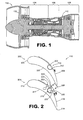
- FIG. 1 is a schematic diagram depicting an exemplary embodiment of a gas turbine engine.
- FIG. 2 is a schematic diagram depicting adjacent vanes of the turbine section of the embodiment of FIG. 1 .
- FIGS. 3A - 3C depict an exemplary embodiment of a variable vane, with a barrel of the vane being shown rotated to different positions.
- a throat area between adjacent vanes is altered by moving a barrel located on a suction side of one of the vanes.
- the barrel is rotatable such that an exterior of the barrel can mechanically alter the throat area between the adjacent vanes.
- one or more fluidic jets can be used to additionally alter the throat area and/or modify flow characteristics of the gas flow path in a vicinity of the barrel.
- FIG. 1 depicts an exemplary embodiment of a gas turbine engine.
- engine 100 incorporates a fan 102, a compressor section 104, a combustion section 106 and a turbine section 108.
- turbine section 108 incorporates a variable vane assembly 110, which will be described in greater detail with respect to FIG. 2 .
- FIG. 1 depicted in FIG. 1 is a turbofan gas turbine engine, there is no intention to limit the concepts described herein to use with turbofans, as various other types of gas turbine engines can be used.
- vanes 202 and 204 are stationary vanes that are spaced from each other to define a throat area (A) that is defined as the narrowest region between the vanes.
- Vane 202 includes a leading edge 205, a trailing edge 206, a pressure side 207 and a suction side 208, forming a radially extending airfoil.
- a moveable (e.g., rotatable) barrel 209 is positioned along the suction side.
- a cavity 210 includes an aperture 212 that is located in the suction side. The barrel is positioned within the cavity and is moveable therein about its radial axis.
- vane 204 includes a leading edge 215, a trailing edge 216, a pressure side 217 and a suction side 218. Vane 204 also incorporates a moveable (e.g., rotatable) barrel 219, as well as a fluidic jet 220.
- a cavity 222 includes an aperture 224 that is located in the suction side 218.
- the barrel 219 is positioned within the cavity and is moveable therein.
- At least a portion of the barrel 219 extends through the aperture 224 and outwardly from the suction side 218.
- a surface 226 of the barrel is generally flush with the suction side 218.
- the throat area (A) is created by surface 207 and either surface 218 or 226, depending on which surface (218 or 226) is closest to surface 207.
- portion 228 of the barrel protrudes outwardly from the suction side, thereby mechanically altering the throat area (B).
- fluidic jet 220 of vane 204 can be operated to control the flow upstream of the portion 228 of the barrel protruding from surface 218.
- the fluidic jet is positioned and angled with respect to surface 218 to control the incoming, near surface, boundary layer to prevent flow separation immediately upstream and downstream of the protruding barrel portion 228.
- the fluidic jet energizes the near surface flow by imparting flow momentum to the flow between vanes 202 and 204 and through the throat area (B), thereby preventing flow separation from surface 218 and the associated losses accompanying flow separation.
- vane 300 incorporates a barrel 302'that includes multiple channels that communicate with an interior plenum 304 of the vane.
- the plenum receives a flow of air, for example from compressor 104 ( FIG. 1 ), that can be used to form fluidic jets.
- three non-communicating channels 306, 307 and 308 are depicted.
- Barrel 302 is generally a cylindrical structure that extends along a longitudinal axis 310 within a cavity 311 between a root and a tip of the vane.
- barrel 302 is oriented in a first or neutral position, in which a surface 312 of the barrel is generally flush with a suction side surface 314 of the vane.
- channel 306 pneumatically communicates with the plenum.
- air from the plenum can be directed (e.g., continuously or intermittently) through the channel 306 and into the gas flow path located between the suction side surface and the pressure side surface of an adjacent vane (not shown).
- one or more positions of the barrel such as the neutral position, can correspond to no channels communicating with a plenum.
- multiple channels 306 may extend from root to tip along the longitudinal axis.
- FIG. 3B depicts the barrel rotated to a second position, in which the surface 312 of the barrel is no longer flush with the suction side surface. Specifically, a portion 320 of the barrel now protrudes from the suction side surface, whereas another portion 322 of the barrel is positioned within the cavity. Additionally, in the second position, channel 307 pneumatically communicates with the plenum, thereby enabling air to be directed through channel 307. It should be noted that in this embodiment, when air is being directed into channel 307, air is no longer being directed into another channel. In other embodiments, however, air can be provided to multiple channels simultaneously.
- the barrel is rotated to a third position, in which the surface 312 of the barrel is not flush with the suction side surface. Specifically, portion 322 of the barrel protrudes from the suction side surface, with portion 320 of the barrel being positioned within the cavity. Additionally, in the third position, channel 308 pneumatically communicates with the plenum, thereby enabling air to be directed through channel 308.
- air can be provided from the plenum and through a channel of sufficient volume and pressure to form a fluidic jet at the outlet of the channel.
- a fluidic jet can be used to augment the gas flow path in a vicinity of the barrel in order to reduce a potential for flow separation from the suction side surface.
- a fluidic jet can be used to influence the throat area directly, such as by repositioning the streamline flow in a vicinity of the fluidic jet.
- the embodiment of FIGS 3A-3C can be used to modify the throat area mechanically (using the barrel) and fluidicly (using a fluidic jet from an outlet of a channel).
- a fluidic jet can be controlled independently of positioning of the barrel such that communication of the channel with the plenum does not necessarily dictate whether air is provided from the plenum to the channel. It should also be noted that in some embodiments, two or more of the channels can communicate with each other such that air provided by the plenum to one of the channels can be emitted by outlets of multiple channels. This is in contrast to the independent channel arrangement of the embodiment of FIGS 3A-3C .
- Actuation of a barrel between various positions can be accomplished in various manners.
- trunnions, arms, and/or synchronization rings can be used, with actuation occurring either internal or external to the engine casing.
- a gear-driven arrangement can be used.
- a barrel can be mounted to a vane assembly, in which the vane associated with the barrel can be either stationary or moveable.
Landscapes
- Engineering & Computer Science (AREA)
- Mechanical Engineering (AREA)
- General Engineering & Computer Science (AREA)
- Physics & Mathematics (AREA)
- Fluid Mechanics (AREA)
- Structures Of Non-Positive Displacement Pumps (AREA)
- Turbine Rotor Nozzle Sealing (AREA)
Abstract
Description
- The disclosure generally relates to gas turbine engines.
- Gas turbine engines use compressors to compress gas for combustion. In particular, a compressor typically uses alternating sets of rotating blades and stationary vanes to compress gas. Gas flowing through such a compressor is forced between the sets and between adjacent blades and vanes of a given set. Similarly, after combustion, hot expanding gas drives a turbine that has sets of rotating blades and stationary vanes.
- Gas turbine engine systems involving mechanically alterable vane throat areas are provided. In this regard, an exemplary embodiment of a vane for a gas turbine engine comprises: a leading edge; a trailing edge; a suction side surface extending between the leading edge and the trailing edge; a cavity having an aperture located in the suction side surface; and a barrel located within the cavity and being moveable therein such that movement of the barrel alters an extent to which the barrel protrudes through the aperture.
- An exemplary embodiment of a vane assembly for a gas turbine engine comprises: a vane having a pressure side; and an adjacent vane having a suction side located adjacent to the pressure side, the vane and the adjacent vane defining a throat area therebetween, the suction side of the adjacent vane having a cavity and a barrel retained by the cavity, the barrel being moveable such that movement of the barrel alters the throat area. The fluidic jet may be movable with the barrel. The barrel may be operative to rotate about a rotational axis. The barrel may lack rotational symmetry.
- An exemplary embodiment of a gas turbine engine comprises: a vane assembly having a vane and an adjacent vane; the vane having a pressure side; and the adjacent vane having a suction side located adjacent to the pressure side, the vane and the adjacent vane defining a throat area therebetween, the suction side of the adjacent vane having a cavity and a barrel retained by the cavity, the barrel being moveable such that movement of the barrel alters the throat area. The engine may be a turbofan engine. The vane assembly may be a high pressure turbine vane assembly.
- Other systems, methods, features and/or advantages of this disclosure will be or may become apparent to one with skill in the art upon examination of the following drawings and detailed description. It is intended that all such additional systems, methods, features and/or advantages be included within this description and be within the scope of the present disclosure.
- Many aspects of the disclosure can be better understood with reference to the following drawings. The components in the drawings are not necessarily to scale. Moreover, in the drawings, like reference numerals designate corresponding parts throughout the several views.
-
FIG. 1 is a schematic diagram depicting an exemplary embodiment of a gas turbine engine. -
FIG. 2 is a schematic diagram depicting adjacent vanes of the turbine section of the embodiment ofFIG. 1 . -
FIGS. 3A - 3C depict an exemplary embodiment of a variable vane, with a barrel of the vane being shown rotated to different positions. - Gas turbine engine systems involving mechanically alterable vane throat areas are provided, several exemplary embodiments of which will be described in detail. In some embodiments, a throat area between adjacent vanes is altered by moving a barrel located on a suction side of one of the vanes. The barrel is rotatable such that an exterior of the barrel can mechanically alter the throat area between the adjacent vanes. In some embodiments, one or more fluidic jets can be used to additionally alter the throat area and/or modify flow characteristics of the gas flow path in a vicinity of the barrel.
- In this regard, reference is made to the schematic diagram of
FIG. 1 , which depicts an exemplary embodiment of a gas turbine engine. As shown inFIG. 1 ,engine 100 incorporates afan 102, acompressor section 104, acombustion section 106 and aturbine section 108. Notably,turbine section 108 incorporates avariable vane assembly 110, which will be described in greater detail with respect toFIG. 2 . Although depicted inFIG. 1 is a turbofan gas turbine engine, there is no intention to limit the concepts described herein to use with turbofans, as various other types of gas turbine engines can be used. - Two adjacent vanes of the
vane assembly 110 are depicted schematically inFIG. 2 . Specifically,vanes edge 205, atrailing edge 206, apressure side 207 and asuction side 208, forming a radially extending airfoil. Along the suction side, a moveable (e.g., rotatable)barrel 209 is positioned. In particular, acavity 210 includes anaperture 212 that is located in the suction side. The barrel is positioned within the cavity and is moveable therein about its radial axis. - Similarly,
vane 204 includes a leadingedge 215, atrailing edge 216, apressure side 217 and asuction side 218. Vane 204 also incorporates a moveable (e.g., rotatable)barrel 219, as well as afluidic jet 220. In particular, acavity 222 includes anaperture 224 that is located in thesuction side 218. Thebarrel 219 is positioned within the cavity and is moveable therein. - In at least some positions, at least a portion of the
barrel 219 extends through theaperture 224 and outwardly from thesuction side 218. Specifically, in a first position (depicted by the dashed lines), asurface 226 of the barrel is generally flush with thesuction side 218. Correspondingly, the throat area (A) is created bysurface 207 and eithersurface surface 207. However, in a second position,portion 228 of the barrel protrudes outwardly from the suction side, thereby mechanically altering the throat area (B). - In the embodiment of
FIG. 2 ,fluidic jet 220 ofvane 204 can be operated to control the flow upstream of theportion 228 of the barrel protruding fromsurface 218. The fluidic jet is positioned and angled with respect tosurface 218 to control the incoming, near surface, boundary layer to prevent flow separation immediately upstream and downstream of the protrudingbarrel portion 228. - The fluidic jet energizes the near surface flow by imparting flow momentum to the flow between
vanes surface 218 and the associated losses accompanying flow separation. - As shown in
FIGS. 3A - 3C , another embodiment of a variable vane is schematically depicted. As shown inFIG. 3A , vane 300 incorporates a barrel 302'that includes multiple channels that communicate with aninterior plenum 304 of the vane. The plenum receives a flow of air, for example from compressor 104 (FIG. 1 ), that can be used to form fluidic jets. In this embodiment, three non-communicatingchannels -
Barrel 302 is generally a cylindrical structure that extends along alongitudinal axis 310 within acavity 311 between a root and a tip of the vane. As shown inFIG. 3A ,barrel 302 is oriented in a first or neutral position, in which asurface 312 of the barrel is generally flush with asuction side surface 314 of the vane. In the neutral position,channel 306 pneumatically communicates with the plenum. As such, air from the plenum can be directed (e.g., continuously or intermittently) through thechannel 306 and into the gas flow path located between the suction side surface and the pressure side surface of an adjacent vane (not shown). It should be noted that, in other embodiments, one or more positions of the barrel, such as the neutral position, can correspond to no channels communicating with a plenum. Also,multiple channels 306 may extend from root to tip along the longitudinal axis. - In contrast,
FIG. 3B depicts the barrel rotated to a second position, in which thesurface 312 of the barrel is no longer flush with the suction side surface. Specifically, aportion 320 of the barrel now protrudes from the suction side surface, whereas anotherportion 322 of the barrel is positioned within the cavity. Additionally, in the second position,channel 307 pneumatically communicates with the plenum, thereby enabling air to be directed throughchannel 307. It should be noted that in this embodiment, when air is being directed intochannel 307, air is no longer being directed into another channel. In other embodiments, however, air can be provided to multiple channels simultaneously. - In
FIG. 3C , the barrel is rotated to a third position, in which thesurface 312 of the barrel is not flush with the suction side surface. Specifically,portion 322 of the barrel protrudes from the suction side surface, withportion 320 of the barrel being positioned within the cavity. Additionally, in the third position,channel 308 pneumatically communicates with the plenum, thereby enabling air to be directed throughchannel 308. - Notably, air can be provided from the plenum and through a channel of sufficient volume and pressure to form a fluidic jet at the outlet of the channel. In some embodiments, a fluidic jet can be used to augment the gas flow path in a vicinity of the barrel in order to reduce a potential for flow separation from the suction side surface. Additionally or alternatively, a fluidic jet can be used to influence the throat area directly, such as by repositioning the streamline flow in a vicinity of the fluidic jet. As an example, the embodiment of
FIGS 3A-3C can be used to modify the throat area mechanically (using the barrel) and fluidicly (using a fluidic jet from an outlet of a channel). - In some embodiments, a fluidic jet can be controlled independently of positioning of the barrel such that communication of the channel with the plenum does not necessarily dictate whether air is provided from the plenum to the channel. It should also be noted that in some embodiments, two or more of the channels can communicate with each other such that air provided by the plenum to one of the channels can be emitted by outlets of multiple channels. This is in contrast to the independent channel arrangement of the embodiment of
FIGS 3A-3C . - Actuation of a barrel between various positions can be accomplished in various manners. By way of example, trunnions, arms, and/or synchronization rings can be used, with actuation occurring either internal or external to the engine casing. As another example, a gear-driven arrangement can be used. In some embodiments, a barrel can be mounted to a vane assembly, in which the vane associated with the barrel can be either stationary or moveable.
- It should be emphasized that the above-described embodiments are merely possible examples of implementations set forth for a clear understanding of the principles of this disclosure. Many variations and modifications may be made to the above-described embodiments without departing substantially from the principles of the disclosure. All such modifications and variations are intended to be included herein within the scope of this disclosure and protected by the accompanying claims.
Claims (15)
- A vane (204; 300) for a gas turbine engine comprising:a leading edge (215);a trailing edge (216);a suction side surface (218; 314) extending between the leading edge (215) and the trailing edge (216);a cavity (222; 311) having an aperture (224) located in the suction side surface (218; 314); anda barrel (219; 302) located within the cavity (222; 311) and being moveable therein such that movement of the barrel (219; 302) alters an extent to which the barrel (219; 302) protrudes through the aperture (224).
- The vane of claim 1, further comprising a fluidic jet (220) having an outlet port operative to emit gas into a gas flow path located adjacent to the suction side surface (218).
- The vane of claim 2, wherein the outlet port of the fluidic jet (220) is positioned upstream of the barrel (219).
- The vane of claim 2, wherein the outlet port of the fluidic jet is moveable with the barrel (302).
- The vane of claim 4, wherein the outlet port is a first of multiple outlet ports moveable with the barrel (302).
- The vane of claim 5, wherein at least two of the outlet ports are located at different radial positions with respect to a rotational axis of the barrel (302).
- The vane of any preceding claim, wherein the barrel (219; 302) is rotatable through a range of positions, with a first of the positions corresponding to a portion of the exterior surface of the barrel (219; 302) being flush with the suction side surface (218; 314).
- The vane of claim 7, wherein a second of the positions corresponds to the portion of the exterior surface of the barrel (219; 302) protruding from the aperture (224).
- The vane of claim 7, wherein:the barrel (302) mounts an outlet port of a fluidic jet;in the second of the positions, the outlet port is not positioned to emit gas into a gas flow path located adjacent to the suction side surface (314); andin a third of the positions, the outlet port is positioned to emit gas into the gas flow path.
- The vane of any of claims 4 to 9, wherein:the vane (300) further comprises a plenum (304) pneumatically communicating with the cavity;the barrel (302) has a channel (306) extending between an inlet and an outlet, the barrel (302) being selectively moveable between a first position, in which the inlet is aligned with the plenum (304) such that gas from the plenum is directed through the channel (306) and out of the outlet and, a second position, in which the inlet is not aligned with the plenum (304).
- The vane of any preceding claim, wherein the vane (204; 300) is a stationary vane.
- A vane assembly for a gas turbine engine comprising:a vane (202) having a pressure side (217); andan adjacent vane (204) having a suction side (218) located adjacent to the pressure side (217), the vane (202) and the adjacent vane (204) defining a throat area (A) therebetween, the suction side (218) of the adjacent vane (204) having a cavity (222) and a barrel (219) retained by the cavity (222), the barrel (219) being moveable such that movement of the barrel (219) alters the throat area (A).
- The vane assembly of claim 12, further comprising a fluidic jet (220) having an outlet port operative to emit gas into a gas flow path located between the vane (202) and the adjacent vane (204).
- The vane assembly of claim 12 or 13, wherein the fluidic jet is operative to alter the throat area.
- A gas turbine engine comprising:a vane assembly as claimed in any of claims 12 to 14.
Applications Claiming Priority (1)
| Application Number | Priority Date | Filing Date | Title |
|---|---|---|---|
| US11/947,160 US8052388B2 (en) | 2007-11-29 | 2007-11-29 | Gas turbine engine systems involving mechanically alterable vane throat areas |
Publications (2)
| Publication Number | Publication Date |
|---|---|
| EP2065563A2 true EP2065563A2 (en) | 2009-06-03 |
| EP2065563A3 EP2065563A3 (en) | 2012-05-09 |
Family
ID=40270480
Family Applications (1)
| Application Number | Title | Priority Date | Filing Date |
|---|---|---|---|
| EP08253838A Withdrawn EP2065563A3 (en) | 2007-11-29 | 2008-11-28 | Gas turbine engine systems involving mechanically alterable vane throat areas |
Country Status (2)
| Country | Link |
|---|---|
| US (1) | US8052388B2 (en) |
| EP (1) | EP2065563A3 (en) |
Cited By (1)
| Publication number | Priority date | Publication date | Assignee | Title |
|---|---|---|---|---|
| CN113513370A (en) * | 2021-08-26 | 2021-10-19 | 厦门大学 | A forced transition method of low pressure turbine boundary layer based on macroscopic pore structure |
Families Citing this family (16)
| Publication number | Priority date | Publication date | Assignee | Title |
|---|---|---|---|---|
| US10190599B2 (en) | 2016-03-24 | 2019-01-29 | United Technologies Corporation | Drive shaft for remote variable vane actuation |
| US10329947B2 (en) | 2016-03-24 | 2019-06-25 | United Technologies Corporation | 35Geared unison ring for multi-stage variable vane actuation |
| US10329946B2 (en) | 2016-03-24 | 2019-06-25 | United Technologies Corporation | Sliding gear actuation for variable vanes |
| US10415596B2 (en) | 2016-03-24 | 2019-09-17 | United Technologies Corporation | Electric actuation for variable vanes |
| US10107130B2 (en) | 2016-03-24 | 2018-10-23 | United Technologies Corporation | Concentric shafts for remote independent variable vane actuation |
| US10443431B2 (en) | 2016-03-24 | 2019-10-15 | United Technologies Corporation | Idler gear connection for multi-stage variable vane actuation |
| US10301962B2 (en) | 2016-03-24 | 2019-05-28 | United Technologies Corporation | Harmonic drive for shaft driving multiple stages of vanes via gears |
| US10458271B2 (en) | 2016-03-24 | 2019-10-29 | United Technologies Corporation | Cable drive system for variable vane operation |
| US10294813B2 (en) | 2016-03-24 | 2019-05-21 | United Technologies Corporation | Geared unison ring for variable vane actuation |
| US10288087B2 (en) | 2016-03-24 | 2019-05-14 | United Technologies Corporation | Off-axis electric actuation for variable vanes |
| US10443430B2 (en) | 2016-03-24 | 2019-10-15 | United Technologies Corporation | Variable vane actuation with rotating ring and sliding links |
| US10994826B2 (en) * | 2017-01-12 | 2021-05-04 | The Boeing Company | Temperature sensitive self actuated heat boundary layer control device |
| US10760426B2 (en) | 2017-06-13 | 2020-09-01 | General Electric Company | Turbine engine with variable effective throat |
| US10480326B2 (en) * | 2017-09-11 | 2019-11-19 | United Technologies Corporation | Vane for variable area turbine |
| US11014652B1 (en) | 2018-05-03 | 2021-05-25 | Ardura, Inc. | Active lift control device and method |
| US10934883B2 (en) * | 2018-09-12 | 2021-03-02 | Raytheon Technologies | Cover for airfoil assembly for a gas turbine engine |
Family Cites Families (22)
| Publication number | Priority date | Publication date | Assignee | Title |
|---|---|---|---|---|
| US2545010A (en) * | 1945-09-24 | 1951-03-13 | Edward A Stalker | Boundary layer control system for aircraft wings |
| US2852211A (en) * | 1956-09-21 | 1958-09-16 | Xenakis George | Airplane wing with aerodynamically actuated spoiler |
| US3295827A (en) * | 1966-04-06 | 1967-01-03 | Gen Motors Corp | Variable configuration blade |
| JPS60142004A (en) * | 1983-12-28 | 1985-07-27 | Toshiba Corp | Axial flow turbo engine blade |
| DE3505823A1 (en) * | 1985-02-20 | 1986-08-21 | Hans 8038 Gröbenzell Bischoff | Arrangement for influencing the flow on guide or rotor blades for turbo engines |
| DE3540401A1 (en) * | 1985-11-14 | 1987-05-21 | Mtu Muenchen Gmbh | Vane ring for turbo machines, especially for gas turbines |
| DE3542762A1 (en) * | 1985-12-04 | 1987-06-11 | Mtu Muenchen Gmbh | DEVICE FOR CONTROLLING OR CONTROLLING GAS TURBINE ENGINES OR GAS TURBINE JET ENGINES |
| US4856962A (en) * | 1988-02-24 | 1989-08-15 | United Technologies Corporation | Variable inlet guide vane |
| GB2218746B (en) * | 1988-05-17 | 1992-06-17 | Rolls Royce Plc | A nozzle guide vane for a gas turbine engine |
| US5209438A (en) * | 1988-06-20 | 1993-05-11 | Israel Wygnanski | Method and apparatus for delaying the separation of flow from a solid surface |
| GB9203168D0 (en) * | 1992-02-13 | 1992-04-01 | Rolls Royce Plc | Guide vanes for gas turbine engines |
| ES2063636B1 (en) * | 1992-04-23 | 1997-05-01 | Turbo Propulsores Ind | SET OF STATOR BLADES FOR GAS TURBINE ENGINES. |
| FR2714109B1 (en) * | 1993-12-22 | 1996-01-19 | Snecma | Variable camber turbomachine blade. |
| US5549448A (en) * | 1995-02-08 | 1996-08-27 | United Technolgies Corporation | Variable stator vane linkage system and method |
| US5601401A (en) * | 1995-12-21 | 1997-02-11 | United Technologies Corporation | Variable stage vane actuating apparatus |
| JP3638745B2 (en) * | 1997-02-07 | 2005-04-13 | 富士重工業株式会社 | Rotor blade with rotary spoiler |
| IL121164A (en) * | 1997-06-26 | 2002-03-10 | Univ Ramot | Airfoil with dynamic stall control by oscillatory forcing |
| US5931636A (en) * | 1997-08-28 | 1999-08-03 | General Electric Company | Variable area turbine nozzle |
| US6203269B1 (en) * | 1999-02-25 | 2001-03-20 | United Technologies Corporation | Centrifugal air flow control |
| US6461105B1 (en) * | 2001-05-31 | 2002-10-08 | United Technologies Corporation | Variable vane for use in turbo machines |
| US7278819B2 (en) * | 2005-07-05 | 2007-10-09 | General Electric Company | Variable stator vane lever arm assembly and method of assembling same |
| EP1847682A1 (en) * | 2006-04-21 | 2007-10-24 | Siemens Aktiengesellschaft | Method for supplying a fluid to the main gas stream in a turbine and associated turbine blade. |
-
2007
- 2007-11-29 US US11/947,160 patent/US8052388B2/en active Active
-
2008
- 2008-11-28 EP EP08253838A patent/EP2065563A3/en not_active Withdrawn
Cited By (1)
| Publication number | Priority date | Publication date | Assignee | Title |
|---|---|---|---|---|
| CN113513370A (en) * | 2021-08-26 | 2021-10-19 | 厦门大学 | A forced transition method of low pressure turbine boundary layer based on macroscopic pore structure |
Also Published As
| Publication number | Publication date |
|---|---|
| EP2065563A3 (en) | 2012-05-09 |
| US8052388B2 (en) | 2011-11-08 |
| US20090142181A1 (en) | 2009-06-04 |
Similar Documents
| Publication | Publication Date | Title |
|---|---|---|
| US8052388B2 (en) | Gas turbine engine systems involving mechanically alterable vane throat areas | |
| EP2014871B1 (en) | Systems and methods involving variable vanes | |
| CN109083690B (en) | Turbine engine with variable effective throat | |
| EP2072756B1 (en) | Systems and methods involving variable throat area vanes | |
| EP1788194A3 (en) | Methods and apparatus for cooling combustion turbine engine components | |
| JP5415532B2 (en) | Air injection into the turbomachine compressor flow path | |
| US20140237987A1 (en) | Gas turbine engine variable geometry flow component | |
| US20220356805A1 (en) | Airfoil assembly with a fluid circuit | |
| US10563518B2 (en) | Gas turbine engine trailing edge ejection holes | |
| CN107448239A (en) | Turbine engine airfoil part releases pumping | |
| JP2021032082A5 (en) | ||
| EP3323979B1 (en) | Airfoil with panel having perimeter seal | |
| CN109891055B (en) | Airfoils for turbine engines and corresponding methods of cooling | |
| US10415407B2 (en) | Airfoil pieces secured with endwall section | |
| CN108691571B (en) | Engine component with flow enhancer | |
| CN107084006B (en) | Accelerator insert for a gas turbine engine airfoil | |
| JP2020139421A (en) | Blade and rotating machine comprising the same | |
| EP2946081B1 (en) | Variable area vane arrangement for a turbine engine | |
| CN115585056A (en) | Non-ducted fan turbine engine with cowl door | |
| CN109083687B (en) | Method and component for a turbine engine to minimize cross flow across cooling holes | |
| CN108691658A (en) | Turbine engine with platform cooling circuit | |
| US10408082B2 (en) | Airfoil with retention pocket holding airfoil piece | |
| EP3324004A1 (en) | Airfoil with retention pocket holding airfoil piece |
Legal Events
| Date | Code | Title | Description |
|---|---|---|---|
| PUAI | Public reference made under article 153(3) epc to a published international application that has entered the european phase |
Free format text: ORIGINAL CODE: 0009012 |
|
| AK | Designated contracting states |
Kind code of ref document: A2 Designated state(s): AT BE BG CH CY CZ DE DK EE ES FI FR GB GR HR HU IE IS IT LI LT LU LV MC MT NL NO PL PT RO SE SI SK TR |
|
| AX | Request for extension of the european patent |
Extension state: AL BA MK RS |
|
| PUAL | Search report despatched |
Free format text: ORIGINAL CODE: 0009013 |
|
| AK | Designated contracting states |
Kind code of ref document: A3 Designated state(s): AT BE BG CH CY CZ DE DK EE ES FI FR GB GR HR HU IE IS IT LI LT LU LV MC MT NL NO PL PT RO SE SI SK TR |
|
| AX | Request for extension of the european patent |
Extension state: AL BA MK RS |
|
| RIC1 | Information provided on ipc code assigned before grant |
Ipc: F01D 9/02 20060101ALI20120405BHEP Ipc: F01D 5/14 20060101AFI20120405BHEP |
|
| 17P | Request for examination filed |
Effective date: 20121106 |
|
| AKX | Designation fees paid |
Designated state(s): DE GB |
|
| STAA | Information on the status of an ep patent application or granted ep patent |
Free format text: STATUS: THE APPLICATION HAS BEEN WITHDRAWN |
|
| 18W | Application withdrawn |
Effective date: 20140513 |