EP2065194A2 - Apparatus and method for decorating objects - Google Patents
Apparatus and method for decorating objects Download PDFInfo
- Publication number
- EP2065194A2 EP2065194A2 EP08160185A EP08160185A EP2065194A2 EP 2065194 A2 EP2065194 A2 EP 2065194A2 EP 08160185 A EP08160185 A EP 08160185A EP 08160185 A EP08160185 A EP 08160185A EP 2065194 A2 EP2065194 A2 EP 2065194A2
- Authority
- EP
- European Patent Office
- Prior art keywords
- decorating
- transferring
- ink
- objects
- jet printing
- Prior art date
- Legal status (The legal status is an assumption and is not a legal conclusion. Google has not performed a legal analysis and makes no representation as to the accuracy of the status listed.)
- Withdrawn
Links
- 238000000034 method Methods 0.000 title claims abstract description 21
- 238000007641 inkjet printing Methods 0.000 claims abstract description 48
- 238000000151 deposition Methods 0.000 claims abstract description 9
- 239000000919 ceramic Substances 0.000 claims description 61
- 239000000463 material Substances 0.000 claims description 31
- 238000004140 cleaning Methods 0.000 description 15
- 238000007639 printing Methods 0.000 description 11
- 238000004519 manufacturing process Methods 0.000 description 9
- 239000013536 elastomeric material Substances 0.000 description 5
- 239000000049 pigment Substances 0.000 description 5
- 239000000843 powder Substances 0.000 description 5
- 239000002245 particle Substances 0.000 description 4
- 238000003825 pressing Methods 0.000 description 4
- 238000011144 upstream manufacturing Methods 0.000 description 4
- 229910010293 ceramic material Inorganic materials 0.000 description 3
- 238000005034 decoration Methods 0.000 description 3
- 238000001035 drying Methods 0.000 description 3
- 230000000694 effects Effects 0.000 description 3
- 239000007788 liquid Substances 0.000 description 3
- 229920002379 silicone rubber Polymers 0.000 description 3
- 239000004945 silicone rubber Substances 0.000 description 3
- 239000000654 additive Substances 0.000 description 2
- 239000012530 fluid Substances 0.000 description 2
- 239000002994 raw material Substances 0.000 description 2
- 239000005871 repellent Substances 0.000 description 2
- 239000000126 substance Substances 0.000 description 2
- PLXMOAALOJOTIY-FPTXNFDTSA-N Aesculin Natural products OC[C@@H]1[C@@H](O)[C@H](O)[C@@H](O)[C@H](O)[C@H]1Oc2cc3C=CC(=O)Oc3cc2O PLXMOAALOJOTIY-FPTXNFDTSA-N 0.000 description 1
- 239000002253 acid Substances 0.000 description 1
- 239000007900 aqueous suspension Substances 0.000 description 1
- 239000003086 colorant Substances 0.000 description 1
- 238000001704 evaporation Methods 0.000 description 1
- 230000008020 evaporation Effects 0.000 description 1
- 239000011521 glass Substances 0.000 description 1
- 238000010438 heat treatment Methods 0.000 description 1
- 239000000976 ink Substances 0.000 description 1
- 238000010147 laser engraving Methods 0.000 description 1
- 239000000203 mixture Substances 0.000 description 1
- 230000003014 reinforcing effect Effects 0.000 description 1
- XLYOFNOQVPJJNP-UHFFFAOYSA-N water Substances O XLYOFNOQVPJJNP-UHFFFAOYSA-N 0.000 description 1
Images

Classifications
-
- B—PERFORMING OPERATIONS; TRANSPORTING
- B41—PRINTING; LINING MACHINES; TYPEWRITERS; STAMPS
- B41F—PRINTING MACHINES OR PRESSES
- B41F17/00—Printing apparatus or machines of special types or for particular purposes, not otherwise provided for
- B41F17/007—Use of printing belts
-
- B—PERFORMING OPERATIONS; TRANSPORTING
- B28—WORKING CEMENT, CLAY, OR STONE
- B28B—SHAPING CLAY OR OTHER CERAMIC COMPOSITIONS; SHAPING SLAG; SHAPING MIXTURES CONTAINING CEMENTITIOUS MATERIAL, e.g. PLASTER
- B28B11/00—Apparatus or processes for treating or working the shaped or preshaped articles
- B28B11/04—Apparatus or processes for treating or working the shaped or preshaped articles for coating or applying engobing layers
- B28B11/046—Apparatus or processes for treating or working the shaped or preshaped articles for coating or applying engobing layers by rolling
-
- B—PERFORMING OPERATIONS; TRANSPORTING
- B41—PRINTING; LINING MACHINES; TYPEWRITERS; STAMPS
- B41J—TYPEWRITERS; SELECTIVE PRINTING MECHANISMS, i.e. MECHANISMS PRINTING OTHERWISE THAN FROM A FORME; CORRECTION OF TYPOGRAPHICAL ERRORS
- B41J2/00—Typewriters or selective printing mechanisms characterised by the printing or marking process for which they are designed
- B41J2/005—Typewriters or selective printing mechanisms characterised by the printing or marking process for which they are designed characterised by bringing liquid or particles selectively into contact with a printing material
- B41J2/0057—Typewriters or selective printing mechanisms characterised by the printing or marking process for which they are designed characterised by bringing liquid or particles selectively into contact with a printing material where an intermediate transfer member receives the ink before transferring it on the printing material
-
- B—PERFORMING OPERATIONS; TRANSPORTING
- B41—PRINTING; LINING MACHINES; TYPEWRITERS; STAMPS
- B41J—TYPEWRITERS; SELECTIVE PRINTING MECHANISMS, i.e. MECHANISMS PRINTING OTHERWISE THAN FROM A FORME; CORRECTION OF TYPOGRAPHICAL ERRORS
- B41J3/00—Typewriters or selective printing or marking mechanisms characterised by the purpose for which they are constructed
- B41J3/407—Typewriters or selective printing or marking mechanisms characterised by the purpose for which they are constructed for marking on special material
-
- B—PERFORMING OPERATIONS; TRANSPORTING
- B41—PRINTING; LINING MACHINES; TYPEWRITERS; STAMPS
- B41J—TYPEWRITERS; SELECTIVE PRINTING MECHANISMS, i.e. MECHANISMS PRINTING OTHERWISE THAN FROM A FORME; CORRECTION OF TYPOGRAPHICAL ERRORS
- B41J11/00—Devices or arrangements of selective printing mechanisms, e.g. ink-jet printers or thermal printers, for supporting or handling copy material in sheet or web form
- B41J11/007—Conveyor belts or like feeding devices
Definitions
- the invention relates to an apparatus and a method for decorating objects, in particular for decorating flat objects, such as ceramic tiles.
- apparatuses comprising an ink-jet printing device that is suppliable with decorating materials containing ceramic pigments.
- the aforesaid apparatuses comprise a conveying device, for example provided with a belt or straps, which supports and moves the ceramic tiles.
- the ink-jet printing device is arranged above the conveying device and deposits on the ceramic tiles the decorating materials - defining a set ornamental pattern - whilst the tiles, moved by the conveying device, pass below the ink-jet printing device.
- the unfired ceramic tiles are introduced in kilns inside which they undergo a heat treatment that consolidates the ceramic material in powder form to obtain a base body of the ceramic tiles and fixes the ceramic glazes and the decorating materials to the aforesaid base body.
- the ceramic glazes are formed of a water suspension of glass particles that are finely ground, mixed with other ceramic raw materials and with additives.
- a drawback of the aforesaid apparatuses is that when the ceramic glazes come into contact with the unfired ceramic tiles that have a high temperature they tend to evaporate. On dispensing nozzles of the ink-jet printing device, drops are thus deposited that prevent the decorating materials from being transferred correctly. In addition, the aforesaid drops may fall on the tiles that pass below the ink-jet printing device causing faults on the finished product.
- particles of the additives that make up the ceramic glazes - conveyed by the steam - may damage, for example corrode, the ink-jet printing device.
- An object of the invention is to improve the decorating apparatuses, in particular for decorating flat objects, such as ceramic tiles.
- a further object is to obtain a decorating apparatus, in particular for decorating flat objects, such as ceramic tiles, which is little subject to wear and requires a reduced supervision by an operator.
- a decorating apparatus comprising ink-jet printing means arranged for dispensing at least a decorating product intended for decorating objects, characterised in that it further comprises transferring means arranged for receiving said at least a decorating product from said ink-jet printing means and depositing said at least a decorating product on said objects.
- a method for decorating objects comprising dispensing by ink-jet printing means at least a decorating product intended for decorating said objects, characterised in that it further comprises distributing said at least a decorating product on transferring means and transferring said at least a decorating product from said transferring means to said objects.
- the ink-jet printing means comprises printing heads that do not directly face the objects, as occurs in the known apparatuses, but face the transferring means and are spaced away from the objects.
- the aforesaid heads do not tend to get soiled by - or become damaged by - substances, in particular in steam state, coming from the objects.
- the steams coming from the objects is lost in the surrounding environment and is not deposited on the aforesaid printing heads.
- the transferring means comprises transferring belt means, or transferring roller means, provided with a smooth transfer surface intended for receiving said at least a decorating product.
- the transferring belt means, or the transferring roller means comprises a reticulated transferring surface intended for receiving said at least a decorating product.
- the transferring means comprises cleaning means arranged for removing from the transferring belt means, or from the transferring roller means, residues of said at least a decorating product.
- the cleaning means comprises a cleaning roller.
- the cleaning means comprises a cleaning doctor blade.
- the cleaning means comprises dispensing means arranged for dispensing a fluid on the transferring belt means, or on the transferring roller means.
- the transferring belt means comprises a closed-loop belt.
- the closed-loop belt extends between a driving roller and an idling roller, the driving roller and the idling roller are arranged on a substantially vertical plane.
- the transferring roller means comprises a tubular sleeve that is rotatable around a longitudinal axis thereof.
- the tubular sleeve has a hollow cylindrical shape.
- the decorating apparatus comprises conveying means arranged for moving the objects along an advancing direction and for making the objects interact with the transferring means.
- the transferring belt means is arranged transversely with respect to the conveying means and to said advancing direction.
- the transferring belt means is arranged substantially perpendicularly with respect to the conveying means and to said advancing direction.
- the decorating apparatus moreover comprises further transferring means arranged for depositing decorating material on the objects.
- the further transferring means is arranged upstream of the transferring means with respect to said advancing direction.
- the further transferring means is provided with cavities arranged for receiving the decorating material and for depositing the decorating material on the objects.
- the further transferring means comprises further transferring belt means, or further transferring roller means.
- the decorating apparatus further comprises doctor-blade means arranged for introducing the decorating material into said cavities and for removing from the further transferring belt means, or from the further transferring roller means, an excess of said decorating material.
- the method comprises removing from the transferring means-i.e. from the transferring belt means, or from the transferring roller means - residues of said at least a decorating product.
- the method comprises moving the objects by conveying means along an advancing direction for making the objects interact with the transferring means.
- the method provides for the transferring belt means being arranged transversely with respect to the conveying means and to said advancing direction.
- the transferring belt means is arranged substantially perpendicularly with respect to the conveying means and to said advancing direction.
- the method further comprises further distributing decorating material on the objects by further transferring means provided with cavities arranged for receiving said decorating material and for arranging said decorating material on the objects.
- the further transferring means comprises further transferring belt means, or further transferring roller means. The method provides for said depositing occurring before said transferring.
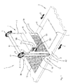
- FIG. 1 With reference to Figures 1 and 2 , there is shown a decorating apparatus 1 arranged for decorating flat objects, such as ceramic tiles 2.
- the decorating apparatus 1 comprises a conveying device 3 arranged for moving the ceramic tiles 2.
- the conveying device 3 comprises a conveyor belt 4 closed in a loop around a driving roller and at least a driven roller.
- the driving roller drives the conveyor belt 4 along an advancing direction D.
- the conveying device 3 may comprise a plurality of belts.
- the decorating apparatus 1 further comprises an ink-jet printing device 5 positioned above the conveying device 3 and provided with printing heads that dispense decorating products 6 containing ceramic pigments.
- the decorating apparatus 1 further comprises a transferring device 7 arranged for receiving the decorating products 6 from the ink-jet printing device 5 and depositing the decorating products 6 on a face 8 of the ceramic tiles 2, the face 8 being intended to be in view after the laying of the ceramic tiles 2.
- the transferring device 7 comprises a tubular transferring element, for example a transferring belt 9 closed in a loop on a first roller 10 and on a second roller 11, the first roller 10 acting as a driving roller and the second roller 11 acting as an idling roller, or vice versa.
- a tubular transferring element for example a transferring belt 9 closed in a loop on a first roller 10 and on a second roller 11, the first roller 10 acting as a driving roller and the second roller 11 acting as an idling roller, or vice versa.
- the decorating products dispensed by the ink-jet printing device 5 can be inks for ink-jet printers comprising ceramic pigments.
- the decorating products 6 may comprise a first cyan-coloured decorating product, a second red-coloured decorating product, a third yellow-coloured decorating product and a fourth black-coloured decorating product.
- the ink-jet printing device 5 can operate in four-colour printing mode.
- the decorating products dispensed by the ink-jet printing device 5 can be traditional ceramic decorating products of the type that is applicable by known silkscreen, flexographic or intaglio decorating machines.
- the traditional ceramic decorating products may comprise a mixture formed by a vehicle in liquid state in which a milled base product (containing ceramic raw materials and vitreous products) and one or more powder pigments are dispersed.
- each decorating product may have a preset colour that depends on the type and quantity of the aforesaid pigments.
- each decorating product can be made according to a corresponding formula to obtain a desired chromatic effect.
- the ink-jet printing device 5 comprises a plurality of dispensing nozzle units, for example a first group of dispensing nozzles 32a arranged for dispensing a decorating product of a first colour, a second group of dispensing nozzles 32b arranged for dispensing a decorating product of a second colour, a third group of dispensing nozzles 32c arranged for dispensing a decorating product of a third colour and a fourth group of dispensing nozzles 32d arranged for dispensing a decorating product of a fourth colour.
- the number of dispensing nozzle units can be different from four.
- the first group of dispensing nozzles 32a, the second group of dispensing nozzles 32b, the third group of dispensing nozzles 32c and the fourth group of dispensing nozzles 32d define four rows of nozzles.
- the aforesaid four rows of nozzles are arranged substantially horizontally and at different vertical quote, so as to be superimposed.
- Each group of nozzles makes on the transferring belt 9 a portion of a decoration that has to be reproduced on the ceramic tiles 2.
- a decoration portion made by a group of dispensing nozzles is not substantially superimposed on a further decoration portion made from a further group of dispensing nozzles.
- a group of dispensing nozzles deposits a decorating product of a certain colour in a zone of the transferring belt 9 and further groups of decorating nozzles deposit further decorating products of further colours in zones of the transferring belt 9 that are different from the aforesaid zone.
- the aforesaid operating modes are controlled by command means that commands the operation of the dispensing nozzles.
- the decorating apparatus 1 by using a sole ink-jet printing device 5, enables the effect of an intaglio decorating machine to be obtained - for example of the type that will be disclosed below - comprising a plurality of belts, or rollers, applicators positioned in sequence along an advancing direction of the ceramic tiles, each belt, or roller, applicator being arranged for depositing a decorating product of a certain colour in a preset zone of the aforesaid ceramic tiles.
- the decorating apparatus 1 enables manufacturing tests of ceramic tiles 2 to be made in a laboratory, or directly on a production line, simulating the effect of an intaglio decorating machine provided with a plurality of applicator belts, or applicator rollers, arranged one after the other along an advancing direction of the ceramic tiles.
- the transferring belt 9 comprises a first toothed belt 16 and a second toothed belt (which is not shown) fixed to an inner surface 17 of the transferring belt 9 at opposite end zones of the transferring belt 9.
- the first toothed belt 16 and the second toothed belt are arranged for engaging toothed portions provided at opposite ends of the first roller 10 and of the second roller 11, or with toothed pulleys fixed to opposite ends of the first roller 10 and of the second roller 11.
- the first roller 10 is rotatable - in a rotation direction R - around a first rotation axis A1 and the second roller 11 is rotatable - in the rotation direction R - around a second rotation axis A2.
- the first roller 10 and the second roller 11 are positioned so that the first rotation axis A1 and the second rotation axis A2 define a substantially vertical plane.
- the transferring belt 9 is positioned so that, at each instant of an operating cycle of the decorating apparatus 1, it is possible to define a first portion 9a of the transferring belt 9 facing the ink-jet printing device 5 and a second portion 9b of the transferring belt 9 facing an opposite part with respect to the ink-jet printing device 5.
- the first portion 9a and the second portion 9b are arranged transversely - in particular substantially perpendicularly - with respect to the conveyor belt 4 and to the advancing direction D.
- the ink-jet printing device 5 is positioned so that the printing heads emits jets of decorating products 6 substantially parallel to the advancing direction D.
- the second roller 11 acts as a pressing element that presses the transferring belt 9 against the face 8.
- ink-jet printing device 5 As the ink-jet printing device 5 is arranged at a considerable distance from the conveyor belt 4, gaseous particles generated by the evaporation of ceramic glazes that were deposited on the ceramic tiles 2 by distributing devices positioned upstream of the decorating apparatus 1 are dispersed in the surrounding environment before interacting with the printing heads of the ink-jet printing device 5.
- the transferring belt 9 can be made of deformable material, in particular elastomeric material such as silicone rubber, so as not to damage the ceramic tiles 2 if they are unfired and therefore very fragile.
- the elastomeric material is impermeable to the decorating products 6 and water-repellent.
- the transferring belt 9, being made of deformable material - i.e. being very soft - can appropriately deposit the decorating products 6 also on tiles having a non-planar face 8.
- the decorating apparatus 1 further comprises detecting means (which is not shown) - for example photocell detecting means - that detects the presence of a ceramic cell 2 to be decorated on the conveyor belt 4 and commands the ink-jet printing device 5.
- detecting means which is not shown
- photocell detecting means that detects the presence of a ceramic cell 2 to be decorated on the conveyor belt 4 and commands the ink-jet printing device 5.
- the cleaning means 14 comprises a cleaning roller 15 facing the second portion 9b of the transferring belt 9.
- a nebulising device In combination with the cleaning roller 15, or with the doctor blade, a nebulising device can be provided that is arranged for nebulising a liquid on the transferring belt 9 that promotes the removal of the aforesaid residues.
- the decorating apparatus 1 is provided with a transferring device 7 comprising a transferring roller 99.
- the transferring roller 99 comprises a tubular sleeve 100 that receives the decorating products 6 and transfers the decorating products 6 to the ceramic tiles 2.
- the tubular sleeve 100 has a substantially cylindrical shape.
- flanges 101 At opposite ends of the tubular sleeve 100 there are provided flanges 101 that enable the transferring roller 99 to be installed on a decorating machine, this machine being provided with driving means that rotates the transferring roller 99 - around a respective longitudinal axis - in the rotation direction R.
- a contrasting element for example a roller, can be provided that presses the tubular sleeve 100 against the face 8 to promote transferring of the decorating products 6 from the tubular sleeve 100 to the ceramic tiles 2.
- the aforesaid pressing element can be not provided.
- the decorating apparatuses 20 are intaglio decorating apparatuses.
- Each further decorating apparatus 20 comprises a further transferring belt 21 closed in a loop on a further first roller 22 and on a further second roller 23, the further first roller 22 acting as a driving roller and the further second roller 23 acting as an idling roller, or vice versa.
- the further transferring belt 21 can be made of deformable material, in particular elastomeric material such as silicone rubber.
- the further transferring belt 21 comprises a further transferring surface 26 provided with a plurality of cavities 27 arranged for receiving a decorating material 28, having a fluid consistency.
- the cavities 27 are arranged so as to make a pattern that has to be reproduced on the ceramic tiles 2.
- the cavities 27 can be obtained by engraving, by a laser engraving device, the further conveyor belt 21.
- Each further decorating apparatus 20 further comprises a doctor blade 29 arranged for interacting with the further transferring surface 26 so as to distribute the decorating material 28 inside the cavities 27 and to remove from the further transferring surface 26 the excess decorating material 28.
- Each decorating apparatus 20 further comprises a supply conduit 31 arranged for supplying the decorating material 28 upstream of the doctor blade 29.
- the doctor blade 29 distributes the decorating material 28 inside the cavity 27. Subsequently, when the further transferring belt 21 interacts with the ceramic tiles 2 supported and moved by the conveyor belt 4, the cavities 27 deposit the decorating material 28 on the face 8.
- each further decorating apparatus 20 can make a pattern having a preset colour on the ceramic tiles 2, after which the decorating apparatus 1 makes a decorative pattern 12 - monochrome or polychrome - that can be varied with extreme facility by a command and control device that commands the ink-jet printing device 5.
- a plurality of decorative patterns 12 can be digitally stored in the command and control device. In this manner, it is possible to obtain ceramic tiles 2 that differ from one another.
- the decorating machine 30 can use only the ink-jet printing technique, maintaining in a non-operating condition the further decorating apparatuses 20 and driving the decorating apparatus 1, or only the intaglio printing technique, maintaining in a non-operating condition the ink-jet printing device 5 and driving the further decorating devices 20.
- the decorating machine 1 is, in fact, provided with a further intaglio printing unit, which enables a further application of decorating material 28 to be applied to the ceramic tiles 2.
- Replacing the transferring belt 9 with the further transferring belt 21 is very simple inasmuch as it is sufficient to move the first roller 10 and the second roller 11 towards one another, remove the transferring belt 9, insert the further transferring belt 21 and move the first roller 10 and the second roller 11 away from one another.
Landscapes
- Engineering & Computer Science (AREA)
- Structural Engineering (AREA)
- Chemical & Material Sciences (AREA)
- Ceramic Engineering (AREA)
- Mechanical Engineering (AREA)
- Ink Jet (AREA)
- Heating, Cooling, Or Curing Plastics Or The Like In General (AREA)
Abstract
Description
- The invention relates to an apparatus and a method for decorating objects, in particular for decorating flat objects, such as ceramic tiles.
- For decorating ceramic tiles, apparatuses are known comprising an ink-jet printing device that is suppliable with decorating materials containing ceramic pigments.
- The aforesaid apparatuses comprise a conveying device, for example provided with a belt or straps, which supports and moves the ceramic tiles. The ink-jet printing device is arranged above the conveying device and deposits on the ceramic tiles the decorating materials - defining a set ornamental pattern - whilst the tiles, moved by the conveying device, pass below the ink-jet printing device.
- In order to obtain ceramic tiles, there is provided pressing a ceramic material in powder form to obtain unfired ceramic tiles, drying the unfired ceramic tiles - in drying devices - to promote the exit of the water contained in the ceramic paste in powder form. Subsequently, there is provided applying ceramic glazes in liquid state to a face of the tiles that is intended to be in view after the laying. The ceramic glazes form a layer on which the aforesaid ink-jet printing device deposits the decorating materials.
The ceramic glazes and the decorating materials are deposited on the unfired ceramic tiles as soon as the unfired ceramic tiles come out of the drying devices and thus have a high temperature. - Subsequently, the unfired ceramic tiles are introduced in kilns inside which they undergo a heat treatment that consolidates the ceramic material in powder form to obtain a base body of the ceramic tiles and fixes the ceramic glazes and the decorating materials to the aforesaid base body.
- The ceramic glazes are formed of a water suspension of glass particles that are finely ground, mixed with other ceramic raw materials and with additives.
- A drawback of the aforesaid apparatuses is that when the ceramic glazes come into contact with the unfired ceramic tiles that have a high temperature they tend to evaporate. On dispensing nozzles of the ink-jet printing device, drops are thus deposited that prevent the decorating materials from being transferred correctly. In addition, the aforesaid drops may fall on the tiles that pass below the ink-jet printing device causing faults on the finished product.
- In addition, particles of the additives that make up the ceramic glazes - conveyed by the steam - may damage, for example corrode, the ink-jet printing device.
- In order to limit the drawbacks mentioned above, periodically stopping the conveying device is provided to enable the ink-jet printing device to be cleaned manually to remove the drops.
- This entails high operating costs, inasmuch as an operator has to be provided who frequently cleans the ink-jet printing device. In addition, the efficiency of the aforesaid apparatuses is greatly penalised due to the interruptions of the operating cycle that are necessary for the cleaning operations.
- An object of the invention is to improve the decorating apparatuses, in particular for decorating flat objects, such as ceramic tiles.
- A further object is to obtain a decorating apparatus, in particular for decorating flat objects, such as ceramic tiles, which is little subject to wear and requires a reduced supervision by an operator.
- In a first aspect of the invention, there is provided a decorating apparatus, comprising ink-jet printing means arranged for dispensing at least a decorating product intended for decorating objects, characterised in that it further comprises transferring means arranged for receiving said at least a decorating product from said ink-jet printing means and depositing said at least a decorating product on said objects.
- In a second aspect of the invention, there is provided a method for decorating objects, comprising dispensing by ink-jet printing means at least a decorating product intended for decorating said objects, characterised in that it further comprises distributing said at least a decorating product on transferring means and transferring said at least a decorating product from said transferring means to said objects.
- Owing to these aspects of the invention, it is possible to obtain a decorating apparatus in which the ink-jet printing means comprises printing heads that do not directly face the objects, as occurs in the known apparatuses, but face the transferring means and are spaced away from the objects. As a result, the aforesaid heads do not tend to get soiled by - or become damaged by - substances, in particular in steam state, coming from the objects.
- Moreover, as the aforesaid printing heads are further from the objects than occurs in prior-art apparatuses, the steams coming from the objects is lost in the surrounding environment and is not deposited on the aforesaid printing heads.
- The transferring means comprises transferring belt means, or transferring roller means, provided with a smooth transfer surface intended for receiving said at least a decorating product. Alternatively, the transferring belt means, or the transferring roller means, comprises a reticulated transferring surface intended for receiving said at least a decorating product.
- The transferring means comprises cleaning means arranged for removing from the transferring belt means, or from the transferring roller means, residues of said at least a decorating product. The cleaning means comprises a cleaning roller. Alternatively, the cleaning means comprises a cleaning doctor blade. The cleaning means comprises dispensing means arranged for dispensing a fluid on the transferring belt means, or on the transferring roller means.
- In an embodiment, the transferring belt means comprises a closed-loop belt. The closed-loop belt extends between a driving roller and an idling roller, the driving roller and the idling roller are arranged on a substantially vertical plane.
- In an embodiment, the transferring roller means comprises a tubular sleeve that is rotatable around a longitudinal axis thereof. The tubular sleeve has a hollow cylindrical shape.
- The decorating apparatus comprises conveying means arranged for moving the objects along an advancing direction and for making the objects interact with the transferring means. The transferring belt means is arranged transversely with respect to the conveying means and to said advancing direction. In particular, the transferring belt means is arranged substantially perpendicularly with respect to the conveying means and to said advancing direction.
- The decorating apparatus moreover comprises further transferring means arranged for depositing decorating material on the objects. The further transferring means is arranged upstream of the transferring means with respect to said advancing direction. The further transferring means is provided with cavities arranged for receiving the decorating material and for depositing the decorating material on the objects. The further transferring means comprises further transferring belt means, or further transferring roller means. The decorating apparatus further comprises doctor-blade means arranged for introducing the decorating material into said cavities and for removing from the further transferring belt means, or from the further transferring roller means, an excess of said decorating material.
- The method comprises removing from the transferring means-i.e. from the transferring belt means, or from the transferring roller means - residues of said at least a decorating product.
- The method comprises moving the objects by conveying means along an advancing direction for making the objects interact with the transferring means.
- The method provides for the transferring belt means being arranged transversely with respect to the conveying means and to said advancing direction. In particular, the transferring belt means is arranged substantially perpendicularly with respect to the conveying means and to said advancing direction.
- The method further comprises further distributing decorating material on the objects by further transferring means provided with cavities arranged for receiving said decorating material and for arranging said decorating material on the objects. The further transferring means comprises further transferring belt means, or further transferring roller means. The method provides for said depositing occurring before said transferring.
- The invention can be better understood and implemented with reference to the attached drawings, which illustrate some embodiments thereof by way of non-limiting example, in which:
-
Figure 1 is a perspective side view of a decorating apparatus; -
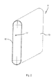
Figure 2 is a perspective side view of a transferring belt of the decorating apparatus inFigure 1 ; -
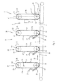
Figure 3 is a schematic side view of a decorating machine comprising the decorating apparatus inFigure 1 cooperating with further decorating apparatuses; -
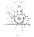
Figure 4 is an enlarged and partially sectioned detail ofFigure 3 ; -
Figure 5 is a view like the one inFigure 1 that shows a version of the decorating apparatus. - With reference to
Figures 1 and2 , there is shown adecorating apparatus 1 arranged for decorating flat objects, such asceramic tiles 2. - The
decorating apparatus 1 comprises aconveying device 3 arranged for moving theceramic tiles 2. Theconveying device 3 comprises aconveyor belt 4 closed in a loop around a driving roller and at least a driven roller. The driving roller drives theconveyor belt 4 along an advancing direction D. - Alternatively to the
conveyor belt 4, theconveying device 3 may comprise a plurality of belts. - The
decorating apparatus 1 further comprises an ink-jet printing device 5 positioned above theconveying device 3 and provided with printing heads that dispense decoratingproducts 6 containing ceramic pigments. - The
decorating apparatus 1 further comprises a transferringdevice 7 arranged for receiving thedecorating products 6 from the ink-jet printing device 5 and depositing thedecorating products 6 on aface 8 of theceramic tiles 2, theface 8 being intended to be in view after the laying of theceramic tiles 2. - The transferring
device 7 comprises a tubular transferring element, for example atransferring belt 9 closed in a loop on afirst roller 10 and on asecond roller 11, thefirst roller 10 acting as a driving roller and thesecond roller 11 acting as an idling roller, or vice versa. - In an embodiment, the decorating products dispensed by the ink-
jet printing device 5 can be inks for ink-jet printers comprising ceramic pigments. - The
decorating products 6 may comprise a first cyan-coloured decorating product, a second red-coloured decorating product, a third yellow-coloured decorating product and a fourth black-coloured decorating product. - In this case, the ink-
jet printing device 5 can operate in four-colour printing mode. - In another embodiment, the decorating products dispensed by the ink-
jet printing device 5 can be traditional ceramic decorating products of the type that is applicable by known silkscreen, flexographic or intaglio decorating machines. - The traditional ceramic decorating products may comprise a mixture formed by a vehicle in liquid state in which a milled base product (containing ceramic raw materials and vitreous products) and one or more powder pigments are dispersed.
- In this case, each decorating product may have a preset colour that depends on the type and quantity of the aforesaid pigments. In other words, each decorating product can be made according to a corresponding formula to obtain a desired chromatic effect.
- The ink-
jet printing device 5 comprises a plurality of dispensing nozzle units, for example a first group of dispensingnozzles 32a arranged for dispensing a decorating product of a first colour, a second group of dispensingnozzles 32b arranged for dispensing a decorating product of a second colour, a third group of dispensingnozzles 32c arranged for dispensing a decorating product of a third colour and a fourth group of dispensingnozzles 32d arranged for dispensing a decorating product of a fourth colour. In embodiments that are not shown, the number of dispensing nozzle units can be different from four. - The first group of dispensing
nozzles 32a, the second group of dispensingnozzles 32b, the third group of dispensingnozzles 32c and the fourth group of dispensingnozzles 32d define four rows of nozzles. The aforesaid four rows of nozzles are arranged substantially horizontally and at different vertical quote, so as to be superimposed. - Each group of nozzles makes on the transferring
belt 9 a portion of a decoration that has to be reproduced on theceramic tiles 2. - In particular, a decoration portion made by a group of dispensing nozzles is not substantially superimposed on a further decoration portion made from a further group of dispensing nozzles. In other words, a group of dispensing nozzles deposits a decorating product of a certain colour in a zone of the transferring
belt 9 and further groups of decorating nozzles deposit further decorating products of further colours in zones of the transferringbelt 9 that are different from the aforesaid zone. - Alternatively, a decorating product deposited by a group of decorating nozzles can be at least partially superimposed on a further decorating product deposited by a further group of dispensing nozzles.
- The aforesaid operating modes are controlled by command means that commands the operation of the dispensing nozzles. The
decorating apparatus 1, by using a sole ink-jet printing device 5, enables the effect of an intaglio decorating machine to be obtained - for example of the type that will be disclosed below - comprising a plurality of belts, or rollers, applicators positioned in sequence along an advancing direction of the ceramic tiles, each belt, or roller, applicator being arranged for depositing a decorating product of a certain colour in a preset zone of the aforesaid ceramic tiles. - The
decorating apparatus 1 enables manufacturing tests ofceramic tiles 2 to be made in a laboratory, or directly on a production line, simulating the effect of an intaglio decorating machine provided with a plurality of applicator belts, or applicator rollers, arranged one after the other along an advancing direction of the ceramic tiles. - At the end of the aforesaid manufacturing tests, once a ceramic tile has been obtained having a desired aesthetic appearance, it is possible to prepare the applicator belts, or applicator rollers of an intaglio decorating machine to make a serial production with the aforesaid intaglio decorating machine. In this manner, only the applicator belts, or applicator rollers, intended for the serial production and not also the applicator belts, or applicator rollers necessary for the manufacturing tests have to be prepared, for example be engraved by laser. This enables a significant reduction in costs to be obtained as during the manufacturing tests it is necessary, proceeding by trials and errors, to provide a large number of test applicator belts, or applicator rollers, having a high unit cost, which, once they have been engraved by laser, cannot be recycled.
- The
apparatus 1, can thus be installed on an already existing production line and be provided with an intaglio decorating machine - or in a laboratory of an existing plant and in which there is installed an intaglio decorating machine - to enable the management of the intaglio decorating machine to be optimised. - Alternatively, the entire serial production can be made with the
decorating apparatus 1, in particular in the case of small batches for which preparing applicator belts, or applicator rollers could be uneconomical. - In a further embodiment, it is possible to provide an ink-jet printing device and, upstream or downstream thereof, a decorating machine of known type, for example a silkscreen, flexographic or intaglio decorating machine, as will be disclosed in greater detail below. This enables a combined decorating mode to be obtained.
- With reference to
Figure 2 , the transferringbelt 9 comprises a firsttoothed belt 16 and a second toothed belt (which is not shown) fixed to aninner surface 17 of the transferringbelt 9 at opposite end zones of the transferringbelt 9. The firsttoothed belt 16 and the second toothed belt are arranged for engaging toothed portions provided at opposite ends of thefirst roller 10 and of thesecond roller 11, or with toothed pulleys fixed to opposite ends of thefirst roller 10 and of thesecond roller 11. - The
first roller 10 is rotatable - in a rotation direction R - around a first rotation axis A1 and thesecond roller 11 is rotatable - in the rotation direction R - around a second rotation axis A2. Thefirst roller 10 and thesecond roller 11 are positioned so that the first rotation axis A1 and the second rotation axis A2 define a substantially vertical plane. - The transferring
belt 9 is positioned so that, at each instant of an operating cycle of thedecorating apparatus 1, it is possible to define afirst portion 9a of the transferringbelt 9 facing the ink-jet printing device 5 and asecond portion 9b of the transferringbelt 9 facing an opposite part with respect to the ink-jet printing device 5. Thefirst portion 9a and thesecond portion 9b are arranged transversely - in particular substantially perpendicularly - with respect to theconveyor belt 4 and to the advancing direction D. - The ink-
jet printing device 5 is positioned so that the printing heads emits jets ofdecorating products 6 substantially parallel to the advancing direction D. - The ink-
jet printing device 5 makes on the transferringbelt 9 adecorative pattern 12 formed by thedecorating products 6, whilst the transferringbelt 9 moves with respect to the ink-jet printing device 5. - During the operation of the
decorating apparatus 1, the transferringbelt 9 and theconveyor belt 4 are driven synchronously. In other words, the transferringbelt 9 is moved at a movement speed that is the same as an advancing speed at which theconveyor belt 4 moves. Consequently, the transferringbelt 9 interacts with theceramic tiles 2 supported by theconveyor belt 4 without sliding with respect to theceramic tiles 2. In this manner, the transferringbelt 9 transfers thedecorative pattern 12 to theface 8 without thedecorative pattern 12 being altered or damaged. - The
second roller 11 acts as a pressing element that presses the transferringbelt 9 against theface 8. - As the ink-
jet printing device 5 is arranged at a considerable distance from theconveyor belt 4, gaseous particles generated by the evaporation of ceramic glazes that were deposited on theceramic tiles 2 by distributing devices positioned upstream of thedecorating apparatus 1 are dispersed in the surrounding environment before interacting with the printing heads of the ink-jet printing device 5. - This prevents drops forming on the printing heads of the ink-
jet printing device 5. Further, this prevents vapours, - possibly containing acid substances - from interacting with the ink-jet printing device 5, corroding the ink-jet printing device 5. - As the gaseous particles are dispersed before reaching the ink-
jet printing device 5, it is not necessary to stop the operation of thedecorating apparatus 1 to perform cleaning operations, in particular to remove the drops from the printing heads. Any drops formed on an external casing of the ink-jet printing device 5 can be removed without stopping the operation of thedecorating apparatus 1. - The transferring
belt 9 can be made of deformable material, in particular elastomeric material such as silicone rubber, so as not to damage theceramic tiles 2 if they are unfired and therefore very fragile. - The elastomeric material is impermeable to the
decorating products 6 and water-repellent. - In addition, the transferring
belt 9, being made of deformable material - i.e. being very soft - can appropriately deposit thedecorating products 6 also on tiles having anon-planar face 8. In particular, it is possible to decorate ceramictiles having faces 8 provided with ridges and depressions obtained by pressing the ceramic material in powder form with moulds provided with an active corrugated surface, in order to confer on theceramic tiles 2 an appearance similar to that of natural materials, for example natural stones. - The transferring
belt 9 comprises a transferringsurface 13, intended for receiving thedecorating products 6, which transferringsurface 13 may be smooth, or be provided with reticulation, in particular a substantially flat reticulation that occupies all the transferringsurface 13, which favours the adhesion of thedecorating products 6 to the transferringbelt 9 and hinders a movement of thedecorating products 6 with respect to the transferringbelt 9 before thedecorating products 6 are transferred to theceramic tiles 2. - The
decorating apparatus 1 further comprises detecting means (which is not shown) - for example photocell detecting means - that detects the presence of aceramic cell 2 to be decorated on theconveyor belt 4 and commands the ink-jet printing device 5. - The
decorating apparatus 1 further comprises cleaning means 14 arranged for removing from the transferringbelt 9 residues ofdecorating products 6 that have not been transferred to theceramic tiles 2. In order to decorate properly edge zones of theceramic tiles 2, it is possible to make on the transferringbelt 9 adecorative pattern 12 having dimensions that are slightly greater than those of theface 8. In this case, the aforesaid residues originate from the quantities of thedecorating products 6 that form the portions of thedecorative pattern 12 that emerge from theface 8 and thus remain on the transferringbelt 9 when the transferringbelt 9 interacts with theceramic tiles 2. - The cleaning means 14 comprises a cleaning
roller 15 facing thesecond portion 9b of the transferringbelt 9. - Alternatively to the cleaning
roller 15, there can be provided a doctor blade. - In combination with the cleaning
roller 15, or with the doctor blade, a nebulising device can be provided that is arranged for nebulising a liquid on the transferringbelt 9 that promotes the removal of the aforesaid residues. - With reference to
Figure 5 , there is shown adecorating apparatus 1 made according to a version. Thedecorating apparatus 1 is provided with atransferring device 7 comprising a transferringroller 99. The transferringroller 99 comprises atubular sleeve 100 that receives thedecorating products 6 and transfers thedecorating products 6 to theceramic tiles 2. Thetubular sleeve 100 has a substantially cylindrical shape. At opposite ends of thetubular sleeve 100 there are providedflanges 101 that enable the transferringroller 99 to be installed on a decorating machine, this machine being provided with driving means that rotates the transferring roller 99 - around a respective longitudinal axis - in the rotation direction R. - The
tubular sleeve 100 can be made of deformable material, in particular elastomeric material such as silicone rubber, so as not to damage theceramic tiles 2 if they are unfired and therefore very fragile. - The elastomeric material is impermeable to the
decorating products 6 and water-repellent. - Inside the transferring roller 99 a contrasting element, for example a roller, can be provided that presses the
tubular sleeve 100 against theface 8 to promote transferring of thedecorating products 6 from thetubular sleeve 100 to theceramic tiles 2. - Alternatively, if the transferring
roller 99 is sufficiently stiff, for example because in the deformable material that forms the tubular sleeve 100 a reinforcing element is submerged, the aforesaid pressing element can be not provided. - The operation of the transferring
roller 99 is similar to that of the transferringbelt 9 that was disclosed above. Similarly, the cleaning means 14 cooperating with the transferringroller 99 is similar to the cleaning means that was disclosed above. - With reference to
Figure 3 , there is shown adecorating machine 30 comprising adecorating apparatus 1 of the type disclosed with reference toFigures 1 and2 and a plurality offurther decorating apparatuses 20. Naturally, the decoratingmachine 30 might comprise adecorating apparatus 1 of the type disclosed with reference toFigure 5 . - The decorating apparatuses 20 are intaglio decorating apparatuses.
- The
further decorating apparatuses 20 are arranged one after the other along the advancing direction D. Thedecorating apparatus 1 is arranged downstream of thefurther decorating apparatuses 20 along the advancing direction D. - Each further decorating
apparatus 20 comprises a further transferringbelt 21 closed in a loop on a furtherfirst roller 22 and on a furthersecond roller 23, the furtherfirst roller 22 acting as a driving roller and the furthersecond roller 23 acting as an idling roller, or vice versa. - In an embodiment that is not shown, each further decorating apparatus comprises - instead of the further transferring belt - a further transferring roller.
- Similarly to what has been disclosed with reference to
Figure 2 , each further transferringbelt 21 comprises a further firsttoothed belt 24 and a further second toothed belt (which is not shown) fixed to a furtherinner surface 25 of the further transferringbelt 21 at opposite end zones of the further transferringbelt 21. The first furthertoothed belt 24 and the second further toothed belt are arranged for engaging toothed portions provided at opposite ends of the furtherfirst roller 22 and of the furthersecond roller 23, or with toothed pulleys fixed to opposite ends of the furtherfirst roller 22 and of the furthersecond roller 23. - The further
first roller 22 is rotatable - in the rotation direction R - around a further first rotation axis B1 and the furthersecond roller 23 is rotatable - in the rotation direction R - around a further second rotation axis B2. The furtherfirst roller 22 and the furthersecond roller 23 are positioned so that the further first rotation axis B1 and the further second rotation axis B2 define a substantially vertical plane. - The further transferring
belt 21 is positioned so that, at each instant of an operating cycle of thefurther decorating apparatus 20, it is possible to define a furtherfirst portion 21a of the further transferringbelt 21 and a furthersecond portion 21b of the further transferringbelt 21 arranged transversely - in particular substantially perpendicularly - with respect to theconveyor belt 4 and to the advancing direction D. - The further transferring
belt 21 can be made of deformable material, in particular elastomeric material such as silicone rubber. - The further transferring
belt 21 comprises a further transferringsurface 26 provided with a plurality ofcavities 27 arranged for receiving adecorating material 28, having a fluid consistency. - The
cavities 27 are arranged so as to make a pattern that has to be reproduced on theceramic tiles 2. - The
cavities 27 can be obtained by engraving, by a laser engraving device, thefurther conveyor belt 21. - Each further decorating
apparatus 20 further comprises adoctor blade 29 arranged for interacting with the further transferringsurface 26 so as to distribute thedecorating material 28 inside thecavities 27 and to remove from the further transferringsurface 26 theexcess decorating material 28. - Each
decorating apparatus 20 further comprises asupply conduit 31 arranged for supplying thedecorating material 28 upstream of thedoctor blade 29. - During the operation of the
further decorating apparatus 20, whilst the further transferringbelt 26 is driven by the driving roller, thedoctor blade 29 distributes thedecorating material 28 inside thecavity 27. Subsequently, when the further transferringbelt 21 interacts with theceramic tiles 2 supported and moved by theconveyor belt 4, thecavities 27 deposit thedecorating material 28 on theface 8. - The decorating
machine 30 is very versatile, as it enables an intaglio decorating technique obtained with thefurther decorating apparatuses 2 to be combined with an ink-jet decorating technique obtained with thedecorating apparatus 1. - In particular, each further decorating
apparatus 20 can make a pattern having a preset colour on theceramic tiles 2, after which thedecorating apparatus 1 makes a decorative pattern 12 - monochrome or polychrome - that can be varied with extreme facility by a command and control device that commands the ink-jet printing device 5. In particular, a plurality ofdecorative patterns 12 can be digitally stored in the command and control device. In this manner, it is possible to obtainceramic tiles 2 that differ from one another. - In addition, the decorating
machine 30 can use only the ink-jet printing technique, maintaining in a non-operating condition thefurther decorating apparatuses 20 and driving thedecorating apparatus 1, or only the intaglio printing technique, maintaining in a non-operating condition the ink-jet printing device 5 and driving thefurther decorating devices 20. - In this last operating mode, it is possible to replace the transferring belt 9 (i.e. a smooth or reticulated belt) with a further transferring belt 21 (i.e. a belt provided with cavities 27) and arrange the
doctor blade 29 and thesupply conduit 31 in an operating configuration. In this case, the decoratingmachine 1 is, in fact, provided with a further intaglio printing unit, which enables a further application of decoratingmaterial 28 to be applied to theceramic tiles 2. - Replacing the transferring
belt 9 with the further transferringbelt 21 is very simple inasmuch as it is sufficient to move thefirst roller 10 and thesecond roller 11 towards one another, remove the transferringbelt 9, insert the further transferringbelt 21 and move thefirst roller 10 and thesecond roller 11 away from one another.
Claims (17)
- Decorating apparatus, comprising ink-jet printing means (5) arranged for dispensing at least a decorating product (6) intended for decorating objects (2), characterised in that it further comprises transferring means (7) arranged for receiving said at least a decorating product (6) from said ink-jet printing means (5) and depositing said at least a decorating product (6) on said objects (2).
- Decorating apparatus according to claim 1, wherein said objects comprise ceramic products (2).
- Decorating apparatus according to claim 1, or 2, and further comprising command means that commands said ink-jet printing means (5) so that said ink-jet printing means (5) deposits a decorating product (6) having a preset colour in a zone of said transferring means (7) and a further decorating material (6) having a further colour in a further zone of said transferring means (7) that is different from said zone.
- Decorating apparatus according to any preceding claim, wherein said ink-jet printing means (5) comprises dispensing nozzle units (32a, 32b, 32c, 32d), each of said dispensing nozzle units (32a, 32b, 32c, 32d) being arranged for dispensing a decorating product (6) having a preset colour.
- Decorating apparatus according to any preceding claim, wherein said transferring means (7) comprises transferring belt means (9).
- Decorating apparatus according to any preceding claim, wherein said transferring means (7) comprises transferring roller means (99).
- Decorating apparatus according to any preceding claim, wherein said transferring means (7) is made of deformable material.
- Decorating apparatus according to any preceding claim, and further comprising conveying means (3) arranged for moving said objects (2) along an advancing direction (D) and for making said objects interact with said transferring means (7).
- Decorating apparatus according to claim 8, wherein said ink-jet printing means (5) comprises dispensing nozzle means (32a, 32b, 32c, 32d) positioned so as to dispense jets of said at least a decorating product (6) substantially parallel to said advancing direction (D).
- Method for decorating objects (2), comprising dispensing by ink-jet printing means (5) at least a decorating product (6) intended for decorating said objects (2), characterised in that it further comprises distributing said at least a decorating product (6) on transferring means (9) and transferring said at least a decorating product (6) from said transferring means (9) to said objects (2).
- Method according to claim 10, wherein said objects comprise ceramic products (2).
- Method according to claim 10, or 11, wherein said dispensing comprises depositing a decorating product (6) having a preset colour in a zone of said transferring means (7) and a further decorating material (6) having a further colour in a further zone of said transferring means (7) that is different from said zone.
- Method according to any one of claims 10 to 12, wherein said transferring means (7) comprises transferring belt means (9).
- Method according to any one of claims 10 to 12, wherein said transferring means (7) comprises transferring roller means (99).
- Method according to any one of claims 10 to 14, wherein said transferring means (7) is made of deformable material.
- Method according to any one of claims 10 to 15, and further comprising moving said objects (2) by conveying means (3) along an advancing direction (D) for making said objects interact with said transferring means (7).
- Method according to claim 16, and further comprising positioning dispensing nozzles (32a, 32b, 32c, 32d) of said ink-jet printing means (5) so as to dispense jets of said at least a decorating product (6) substantially parallel to said advancing direction (D).
Applications Claiming Priority (1)
| Application Number | Priority Date | Filing Date | Title |
|---|---|---|---|
| IT000354A ITMO20070354A1 (en) | 2007-11-23 | 2007-11-23 | APPARATUS AND METHOD FOR DECORATING OBJECTS |
Publications (1)
| Publication Number | Publication Date |
|---|---|
| EP2065194A2 true EP2065194A2 (en) | 2009-06-03 |
Family
ID=40314805
Family Applications (1)
| Application Number | Title | Priority Date | Filing Date |
|---|---|---|---|
| EP08160185A Withdrawn EP2065194A2 (en) | 2007-11-23 | 2008-07-11 | Apparatus and method for decorating objects |
Country Status (2)
| Country | Link |
|---|---|
| EP (1) | EP2065194A2 (en) |
| IT (1) | ITMO20070354A1 (en) |
Cited By (33)
| Publication number | Priority date | Publication date | Assignee | Title |
|---|---|---|---|---|
| EP2275261A1 (en) * | 2009-07-16 | 2011-01-19 | Karl Pedross AG | Device for printing rigid workpieces |
| EP2636531A1 (en) | 2012-03-06 | 2013-09-11 | Flooring Technologies Ltd. | Method for printing the surface of a workpiece |
| US10357963B2 (en) | 2012-03-05 | 2019-07-23 | Landa Corporation Ltd. | Digital printing process |
| US10357985B2 (en) | 2012-03-05 | 2019-07-23 | Landa Corporation Ltd. | Printing system |
| US10427399B2 (en) | 2015-04-14 | 2019-10-01 | Landa Corporation Ltd. | Apparatus for threading an intermediate transfer member of a printing system |
| US10434761B2 (en) | 2012-03-05 | 2019-10-08 | Landa Corporation Ltd. | Digital printing process |
| US10518526B2 (en) | 2012-03-05 | 2019-12-31 | Landa Corporation Ltd. | Apparatus and method for control or monitoring a printing system |
| US10569532B2 (en) | 2012-03-05 | 2020-02-25 | Landa Corporation Ltd. | Digital printing system |
| US10569534B2 (en) | 2012-03-05 | 2020-02-25 | Landa Corporation Ltd. | Digital printing system |
| US10569533B2 (en) | 2012-03-15 | 2020-02-25 | Landa Corporation Ltd. | Endless flexible belt for a printing system |
| US10596804B2 (en) | 2015-03-20 | 2020-03-24 | Landa Corporation Ltd. | Indirect printing system |
| US10632740B2 (en) | 2010-04-23 | 2020-04-28 | Landa Corporation Ltd. | Digital printing process |
| US10642198B2 (en) | 2012-03-05 | 2020-05-05 | Landa Corporation Ltd. | Intermediate transfer members for use with indirect printing systems and protonatable intermediate transfer members for use with indirect printing systems |
| US10759953B2 (en) | 2013-09-11 | 2020-09-01 | Landa Corporation Ltd. | Ink formulations and film constructions thereof |
| US10800936B2 (en) | 2012-03-05 | 2020-10-13 | Landa Corporation Ltd. | Ink film constructions |
| US10889128B2 (en) | 2016-05-30 | 2021-01-12 | Landa Corporation Ltd. | Intermediate transfer member |
| US10926532B2 (en) | 2017-10-19 | 2021-02-23 | Landa Corporation Ltd. | Endless flexible belt for a printing system |
| US10933661B2 (en) | 2016-05-30 | 2021-03-02 | Landa Corporation Ltd. | Digital printing process |
| US10994528B1 (en) | 2018-08-02 | 2021-05-04 | Landa Corporation Ltd. | Digital printing system with flexible intermediate transfer member |
| US11267239B2 (en) | 2017-11-19 | 2022-03-08 | Landa Corporation Ltd. | Digital printing system |
| US11321028B2 (en) | 2019-12-11 | 2022-05-03 | Landa Corporation Ltd. | Correcting registration errors in digital printing |
| US11318734B2 (en) | 2018-10-08 | 2022-05-03 | Landa Corporation Ltd. | Friction reduction means for printing systems and method |
| US11465426B2 (en) | 2018-06-26 | 2022-10-11 | Landa Corporation Ltd. | Intermediate transfer member for a digital printing system |
| US11511536B2 (en) | 2017-11-27 | 2022-11-29 | Landa Corporation Ltd. | Calibration of runout error in a digital printing system |
| US11679615B2 (en) | 2017-12-07 | 2023-06-20 | Landa Corporation Ltd. | Digital printing process and method |
| US11707943B2 (en) | 2017-12-06 | 2023-07-25 | Landa Corporation Ltd. | Method and apparatus for digital printing |
| US11787170B2 (en) | 2018-12-24 | 2023-10-17 | Landa Corporation Ltd. | Digital printing system |
| US11833813B2 (en) | 2019-11-25 | 2023-12-05 | Landa Corporation Ltd. | Drying ink in digital printing using infrared radiation |
| US12001902B2 (en) | 2018-08-13 | 2024-06-04 | Landa Corporation Ltd. | Correcting distortions in digital printing by implanting dummy pixels in a digital image |
| US12011920B2 (en) | 2019-12-29 | 2024-06-18 | Landa Corporation Ltd. | Printing method and system |
| IT202300015225A1 (en) * | 2023-07-20 | 2025-01-20 | Gruppo Tecnoferrari Spa | TILE DECORATING EQUIPMENT |
| US12358277B2 (en) | 2019-03-31 | 2025-07-15 | Landa Corporation Ltd. | Systems and methods for preventing or minimizing printing defects in printing processes |
| US12430453B2 (en) | 2021-02-02 | 2025-09-30 | Landa Corporation Ltd. | Mitigating distortions in printed images |
-
2007
- 2007-11-23 IT IT000354A patent/ITMO20070354A1/en unknown
-
2008
- 2008-07-11 EP EP08160185A patent/EP2065194A2/en not_active Withdrawn
Cited By (33)
| Publication number | Priority date | Publication date | Assignee | Title |
|---|---|---|---|---|
| EP2275261A1 (en) * | 2009-07-16 | 2011-01-19 | Karl Pedross AG | Device for printing rigid workpieces |
| US10632740B2 (en) | 2010-04-23 | 2020-04-28 | Landa Corporation Ltd. | Digital printing process |
| US10642198B2 (en) | 2012-03-05 | 2020-05-05 | Landa Corporation Ltd. | Intermediate transfer members for use with indirect printing systems and protonatable intermediate transfer members for use with indirect printing systems |
| US10357963B2 (en) | 2012-03-05 | 2019-07-23 | Landa Corporation Ltd. | Digital printing process |
| US10434761B2 (en) | 2012-03-05 | 2019-10-08 | Landa Corporation Ltd. | Digital printing process |
| US10518526B2 (en) | 2012-03-05 | 2019-12-31 | Landa Corporation Ltd. | Apparatus and method for control or monitoring a printing system |
| US10569532B2 (en) | 2012-03-05 | 2020-02-25 | Landa Corporation Ltd. | Digital printing system |
| US10569534B2 (en) | 2012-03-05 | 2020-02-25 | Landa Corporation Ltd. | Digital printing system |
| US10357985B2 (en) | 2012-03-05 | 2019-07-23 | Landa Corporation Ltd. | Printing system |
| US10800936B2 (en) | 2012-03-05 | 2020-10-13 | Landa Corporation Ltd. | Ink film constructions |
| EP2636531A1 (en) | 2012-03-06 | 2013-09-11 | Flooring Technologies Ltd. | Method for printing the surface of a workpiece |
| US10569533B2 (en) | 2012-03-15 | 2020-02-25 | Landa Corporation Ltd. | Endless flexible belt for a printing system |
| US10759953B2 (en) | 2013-09-11 | 2020-09-01 | Landa Corporation Ltd. | Ink formulations and film constructions thereof |
| US10596804B2 (en) | 2015-03-20 | 2020-03-24 | Landa Corporation Ltd. | Indirect printing system |
| US10427399B2 (en) | 2015-04-14 | 2019-10-01 | Landa Corporation Ltd. | Apparatus for threading an intermediate transfer member of a printing system |
| US10933661B2 (en) | 2016-05-30 | 2021-03-02 | Landa Corporation Ltd. | Digital printing process |
| US10889128B2 (en) | 2016-05-30 | 2021-01-12 | Landa Corporation Ltd. | Intermediate transfer member |
| US10926532B2 (en) | 2017-10-19 | 2021-02-23 | Landa Corporation Ltd. | Endless flexible belt for a printing system |
| US11267239B2 (en) | 2017-11-19 | 2022-03-08 | Landa Corporation Ltd. | Digital printing system |
| US11511536B2 (en) | 2017-11-27 | 2022-11-29 | Landa Corporation Ltd. | Calibration of runout error in a digital printing system |
| US11707943B2 (en) | 2017-12-06 | 2023-07-25 | Landa Corporation Ltd. | Method and apparatus for digital printing |
| US11679615B2 (en) | 2017-12-07 | 2023-06-20 | Landa Corporation Ltd. | Digital printing process and method |
| US11465426B2 (en) | 2018-06-26 | 2022-10-11 | Landa Corporation Ltd. | Intermediate transfer member for a digital printing system |
| US10994528B1 (en) | 2018-08-02 | 2021-05-04 | Landa Corporation Ltd. | Digital printing system with flexible intermediate transfer member |
| US12001902B2 (en) | 2018-08-13 | 2024-06-04 | Landa Corporation Ltd. | Correcting distortions in digital printing by implanting dummy pixels in a digital image |
| US11318734B2 (en) | 2018-10-08 | 2022-05-03 | Landa Corporation Ltd. | Friction reduction means for printing systems and method |
| US11787170B2 (en) | 2018-12-24 | 2023-10-17 | Landa Corporation Ltd. | Digital printing system |
| US12358277B2 (en) | 2019-03-31 | 2025-07-15 | Landa Corporation Ltd. | Systems and methods for preventing or minimizing printing defects in printing processes |
| US11833813B2 (en) | 2019-11-25 | 2023-12-05 | Landa Corporation Ltd. | Drying ink in digital printing using infrared radiation |
| US11321028B2 (en) | 2019-12-11 | 2022-05-03 | Landa Corporation Ltd. | Correcting registration errors in digital printing |
| US12011920B2 (en) | 2019-12-29 | 2024-06-18 | Landa Corporation Ltd. | Printing method and system |
| US12430453B2 (en) | 2021-02-02 | 2025-09-30 | Landa Corporation Ltd. | Mitigating distortions in printed images |
| IT202300015225A1 (en) * | 2023-07-20 | 2025-01-20 | Gruppo Tecnoferrari Spa | TILE DECORATING EQUIPMENT |
Also Published As
| Publication number | Publication date |
|---|---|
| ITMO20070354A1 (en) | 2009-05-24 |
Similar Documents
| Publication | Publication Date | Title |
|---|---|---|
| ITMO20070354A1 (en) | APPARATUS AND METHOD FOR DECORATING OBJECTS | |
| CN101360591B (en) | An apparatus for decorating ceramic products | |
| EP2892657B1 (en) | Method and machine for the digital decoration of products with granular materials and the like | |
| US9821546B2 (en) | Digital cliche pad printing system and method | |
| AU2004270630B2 (en) | Digital can decorating apparatus | |
| ITMO20070098A1 (en) | PRINT HEAD FOR DECORATIONS OF TILES. | |
| CN104039559A (en) | Foaming a pigment pattern on a substrate | |
| HK1126453A (en) | Apparatus and method for decorating objects | |
| CN118302298A (en) | Ink refill system and method for can decorator | |
| WO2007080059A1 (en) | Method and apparatus for manufacturing articles in the form of slabs or tiles with chromatic effects such as veining and/or spotted effects | |
| EP1336480A1 (en) | Method and device for decoration by silkscreen printing of ceramic tiles or the like | |
| US10035160B2 (en) | Decoration line for ceramic products and process for decorating on ceramic products | |
| EP1977872A2 (en) | Method for decorating a ceramic base support, in particular a tile | |
| CN119947873A (en) | Equipment and processes for decorating ceramic products | |
| EP1208953A2 (en) | Decorating means | |
| JP2014008458A (en) | Coating method of building board, coating apparatus of building board and coated building board | |
| JP4246950B2 (en) | How to paint ceramic building boards | |
| ITMO950174A1 (en) | ROTARY DECORATING MACHINE FOR CERAMIC TILES | |
| JP3580237B2 (en) | How to decorate single-sided tile | |
| JP3130903U (en) | Multi-layer printer for solar panels | |
| JP3790119B2 (en) | How to paint building boards | |
| US2543186A (en) | Apparatus for decorating pottery ware | |
| EP1864773A2 (en) | Method and apparatus for producing ceramic products | |
| EP1590178B1 (en) | Methods and apparatus for decorating items | |
| EP3103605B1 (en) | Device, method and machine for depositing powdered or granulated solids on a surface |
Legal Events
| Date | Code | Title | Description |
|---|---|---|---|
| PUAI | Public reference made under article 153(3) epc to a published international application that has entered the european phase |
Free format text: ORIGINAL CODE: 0009012 |
|
| AK | Designated contracting states |
Kind code of ref document: A2 Designated state(s): AT BE BG CH CY CZ DE DK EE ES FI FR GB GR HR HU IE IS IT LI LT LU LV MC MT NL NO PL PT RO SE SI SK TR |
|
| AX | Request for extension of the european patent |
Extension state: AL BA MK RS |
|
| REG | Reference to a national code |
Ref country code: HK Ref legal event code: DE Ref document number: 1126453 Country of ref document: HK |
|
| STAA | Information on the status of an ep patent application or granted ep patent |
Free format text: STATUS: THE APPLICATION IS DEEMED TO BE WITHDRAWN |
|
| 18D | Application deemed to be withdrawn |
Effective date: 20110201 |
|
| REG | Reference to a national code |
Ref country code: HK Ref legal event code: WD Ref document number: 1126453 Country of ref document: HK |