EP2065003A2 - Endoscope treatment system - Google Patents
Endoscope treatment system Download PDFInfo
- Publication number
- EP2065003A2 EP2065003A2 EP08020533A EP08020533A EP2065003A2 EP 2065003 A2 EP2065003 A2 EP 2065003A2 EP 08020533 A EP08020533 A EP 08020533A EP 08020533 A EP08020533 A EP 08020533A EP 2065003 A2 EP2065003 A2 EP 2065003A2
- Authority
- EP
- European Patent Office
- Prior art keywords
- endoscope
- wires
- portions
- treatment system
- distal end
- Prior art date
- Legal status (The legal status is an assumption and is not a legal conclusion. Google has not performed a legal analysis and makes no representation as to the accuracy of the status listed.)
- Granted
Links
Images



Classifications
-
- A—HUMAN NECESSITIES
- A61—MEDICAL OR VETERINARY SCIENCE; HYGIENE
- A61B—DIAGNOSIS; SURGERY; IDENTIFICATION
- A61B17/00—Surgical instruments, devices or methods
- A61B17/32—Surgical cutting instruments
- A61B17/3205—Excision instruments
- A61B17/3207—Atherectomy devices working by cutting or abrading; Similar devices specially adapted for non-vascular obstructions
- A61B17/320725—Atherectomy devices working by cutting or abrading; Similar devices specially adapted for non-vascular obstructions with radially expandable cutting or abrading elements
-
- A—HUMAN NECESSITIES
- A61—MEDICAL OR VETERINARY SCIENCE; HYGIENE
- A61B—DIAGNOSIS; SURGERY; IDENTIFICATION
- A61B1/00—Instruments for performing medical examinations of the interior of cavities or tubes of the body by visual or photographical inspection, e.g. endoscopes; Illuminating arrangements therefor
- A61B1/00131—Accessories for endoscopes
- A61B1/00135—Oversleeves mounted on the endoscope prior to insertion
-
- A—HUMAN NECESSITIES
- A61—MEDICAL OR VETERINARY SCIENCE; HYGIENE
- A61B—DIAGNOSIS; SURGERY; IDENTIFICATION
- A61B1/00—Instruments for performing medical examinations of the interior of cavities or tubes of the body by visual or photographical inspection, e.g. endoscopes; Illuminating arrangements therefor
- A61B1/012—Instruments for performing medical examinations of the interior of cavities or tubes of the body by visual or photographical inspection, e.g. endoscopes; Illuminating arrangements therefor characterised by internal passages or accessories therefor
- A61B1/018—Instruments for performing medical examinations of the interior of cavities or tubes of the body by visual or photographical inspection, e.g. endoscopes; Illuminating arrangements therefor characterised by internal passages or accessories therefor for receiving instruments
-
- A—HUMAN NECESSITIES
- A61—MEDICAL OR VETERINARY SCIENCE; HYGIENE
- A61B—DIAGNOSIS; SURGERY; IDENTIFICATION
- A61B17/00—Surgical instruments, devices or methods
- A61B17/32—Surgical cutting instruments
- A61B17/3205—Excision instruments
- A61B17/3207—Atherectomy devices working by cutting or abrading; Similar devices specially adapted for non-vascular obstructions
- A61B17/320758—Atherectomy devices working by cutting or abrading; Similar devices specially adapted for non-vascular obstructions with a rotating cutting instrument, e.g. motor driven
-
- A—HUMAN NECESSITIES
- A61—MEDICAL OR VETERINARY SCIENCE; HYGIENE
- A61B—DIAGNOSIS; SURGERY; IDENTIFICATION
- A61B18/00—Surgical instruments, devices or methods for transferring non-mechanical forms of energy to or from the body
- A61B18/04—Surgical instruments, devices or methods for transferring non-mechanical forms of energy to or from the body by heating
- A61B18/12—Surgical instruments, devices or methods for transferring non-mechanical forms of energy to or from the body by heating by passing a current through the tissue to be heated, e.g. high-frequency current
- A61B18/14—Probes or electrodes therefor
- A61B18/1492—Probes or electrodes therefor having a flexible, catheter-like structure, e.g. for heart ablation
-
- A—HUMAN NECESSITIES
- A61—MEDICAL OR VETERINARY SCIENCE; HYGIENE
- A61B—DIAGNOSIS; SURGERY; IDENTIFICATION
- A61B17/00—Surgical instruments, devices or methods
- A61B17/00234—Surgical instruments, devices or methods for minimally invasive surgery
- A61B2017/00292—Surgical instruments, devices or methods for minimally invasive surgery mounted on or guided by flexible, e.g. catheter-like, means
- A61B2017/00336—Surgical instruments, devices or methods for minimally invasive surgery mounted on or guided by flexible, e.g. catheter-like, means with a protective sleeve, e.g. retractable or slidable
-
- A—HUMAN NECESSITIES
- A61—MEDICAL OR VETERINARY SCIENCE; HYGIENE
- A61B—DIAGNOSIS; SURGERY; IDENTIFICATION
- A61B17/00—Surgical instruments, devices or methods
- A61B17/00234—Surgical instruments, devices or methods for minimally invasive surgery
- A61B2017/00292—Surgical instruments, devices or methods for minimally invasive surgery mounted on or guided by flexible, e.g. catheter-like, means
- A61B2017/0034—Surgical instruments, devices or methods for minimally invasive surgery mounted on or guided by flexible, e.g. catheter-like, means adapted to be inserted through a working channel of an endoscope
-
- A—HUMAN NECESSITIES
- A61—MEDICAL OR VETERINARY SCIENCE; HYGIENE
- A61B—DIAGNOSIS; SURGERY; IDENTIFICATION
- A61B17/00—Surgical instruments, devices or methods
- A61B2017/00831—Material properties
- A61B2017/00902—Material properties transparent or translucent
Definitions
- the present invention relates to an endoscope treatment system that uses in combination with an endoscope, a treatment tool that is inserted in a channel of this endoscope, and an overtube that covers an insertion portion of the endoscope or a cap for the endoscope and the like.
- a treatment tool that is used in combination with an endoscope for example a treatment tool for incising a living tissue
- a treatment tool for incising a living tissue there is known one that houses a wire that forms a knife portion in a flexible sheath, or disposes it along the outer surface of the peripheral wall of a flexible sheath, and when actually incising the living tissue, causes a portion of the wire to expand in diameter so as to greatly project to the outside of the flexible sheath, and in this state, by pressing the wire against the required portion of the living tissue that is to be incised while passing a high-frequency current through the wire, thereby making an incision (for example, refer to Published Japanese translation No. H8-509894 of PCT International Publication, and Japanese Unexamined Patent Application, First Publication No. 2004-73582 ).
- the present invention was achieved in view of the above circumstances, and has as its object to provide an endoscope treatment system that is capable of maintaining the desired shape without twisting or bending of a projection portion (treatment portion) that projects outward in the radial direction from a sheath such as a wire for incision and without the projection portion collapsing inadvertently when being subjected to rotation control.
- the endoscope treatment system includes: an endoscope; and a treatment tool that has a sheath that is inserted in a channel of an insertion portion of the endoscope, in which projection portions that project outward from the sheath in the radial direction are provided, and engagement portions that engage the projection portions are provided near the channel of the endoscope.
- the endoscope treatment system includes: an endoscope; a cap that is attached to the distal end of an insertion portion of the endoscope in a non-rotatable manner with respect to the insertion portion; and a treatment tool that has a sheath that is inserted in a channel of the insertion portion of the endoscope, in which projection portions that project outward from the sheath in the radial direction are provided, and engagement portions that engage the projection portions are provided in the cap.
- the projection portions that project outward from the sheath in the radial direction are made to be engaged by the cap of the endoscope, it is possible to obviate an occurrence of twisting or bending of the projection portions by shifting from the radial direction.
- the cap that is attached to the distal end of the insertion portion integrally rotates, and moreover the projection portions that are engaged by this cap also rotate integrally. That is, since it is possible to make the projection portions that project outward from the sheath in the radial direction integrally rotate with the cap of the endoscope, it is possible to prevent the projection portions from suddenly falling when rotating.
- the endoscope treatment system includes: an endoscope; an overtube that covers an insertion portion of the endoscope, and a sheath that is inserted in a channel of the insertion portion of the endoscope, in which projection portions that project outward from the sheath in the radial direction are provided, and engagement portions that engage the projection portions are provided in the distal end of the overtube.
- the projection portions that project outward from the sheath in the radial direction are made to be engaged by the overtube, it is possible to obviate an occurrence of twisting or bending of the projection portions by shifting from the radial direction.
- the engagement portions be slots that engage the projection portions in an inserted state.
- the projection portions and the engagement portions rotate in conjunction with the rotation operation of the insertion portion of the endoscope.
- the projection portions and the engagement portions rotate in conjunction with the rotation operation of this insertion portion.
- the projection portions are disposed near a predetermined position on the screen, and so position of the projection portions is easily confirmed.
- the projection portions freely project and retract.
- the projection portions are placed in a contracted state without projecting outward from the sheath in the radial direction.
- the projections portions After being inserted to the predetermined position in the body cavity, when the treatment is performed, the projections portions are projected outward in the radial direction and are engaged in the engagement portions of the cap or the overtube. In this way, it is possible to use the projection portions by causing them to project outward in the radial direction as necessary, and so the operation when inserting them in the body cavity becomes easy.
- the projection portions be conductive wires to which high-frequency electricity is supplied.
- the cap be transparent.
- the cap be formed in a tapered shape that gradually narrows toward its distal end portion.
- the tapered portion at the distal end of the cap functions as a guide portion when being inserted in the body cavity, insertion becomes easy. Also, by providing the engagement portions along the tapered shape, it is possible to change the radius of the engagement position corresponding to the projection portion. That is, in the case of the engagement position of the engagement portion to the projection portion being at the distal end side of the cap, it is possible to engage a comparatively smaller radius of the projection portion, and on the contrary in the case of being engaged at the proximal end side of the cap, it is possible to engage a comparatively larger radius of the projection portion.
- the projection portions that project outward from the sheath in the radial direction are engaged at the cap or overtube, it is possible to obviate an occurrence of twisting or bending of the projection portion by shifting from the radial direction.
- the incising portion at the distal end of the overtube the incision operation is simplified due to large rotary torque being obtained.
- FIG 1 to FIG 8 show an embodiment of an endoscope treatment system according to the present invention.
- FIG 1 is an overall perspective view of an endoscope treatment system that shows the state of a treatment tool incorporated in an endoscope with a distal end cap
- FIG 2 is a side view that shows the distal end portion of the endoscope treatment system
- FIG. 3 is a side view that shows the state of incising a narrow portion of an esophagus by the endoscope treatment system.
- the endoscope treatment system of this embodiment is provided with an endoscope 2, a cap 7 that is attached to the distal end of an insertion portion 2a of the endoscope 2 in a non-rotatable manner with respect to the insertion portion 2a, and a treatment tool 1 for incision that has a flexible sheath 3 that is inserted in a channel 2b of the insertion portion 2a of the endoscope 2.
- the treatment tool for incision 1 is used by being incorporated in the endoscope 2 as shown in FIG 1 .
- the treatment tool 1 as shown in FIG. 1 and FIG. 2 , is provided with the flexible sheath 3 (sheath) that is inserted into the channel 2b formed in the insertion portion 2a of an endoscope 2, a plurality of wires 5 (projection portions) that are inserted in the flexible sheath 3, and an operation portion 6 that is connected to one end of the wires 5.
- the flexible sheath 3 is made of, for example, a coil sheath, has flexibility, and has an insertion hole 3a that extends along the axis in the interior.
- the wires 5 are respectively inserted in first wire insertion holes 4a that are provided at the distal end portion of the flexible sheath and second wire insertion holes 4b that are provided further to the distal end side of the flexible sheath than the first wire insertion holes 4a. Thereby, a portion of the wires 5 becomes wire exposed portions 10 by being exposed outward of the flexible sheath 3.
- the length of the exposed portions 10 of the wires that are exposed outward of the flexible sheath 3 is adjusted.
- the side at which the operation portion 6 is disposed in the treatment tool 1 is referred to as the proximal end side, and the opposite side is referred to as the distal end side.
- the first wire insertion holes 4a and the second wire insertion holes 4b that are formed in the flexible sheath 3 and through which the plurality of wires 5 are inserted are formed for each wire 5. That is, the first wire insertion holes 4a and the second wire insertion holes 4b are formed in the same number as that of the wires 5.
- the fist wire insertion holes 4a are formed at the same position in the longitudinal direction of the flexible sheath 3
- the second wire insertion holes 4b are formed at the same position in the longitudinal direction of the flexible sheath 3.
- these first and second wire insertion holes 4a, 4b are formed at equal intervals in the circumferential direction.
- the plurality of wires 5, as shown in FIG. 4 each have a proximal end side insertion portion 11 that passes through the interior space of the flexible sheath 3 further to the proximal end side than the first wire insertion hole 4a, the exposed portion 10 that extends from this proximal end side insertion portion 11 toward the distal end side, passes through the first wire insertion hole 4a, and is exposed outward of the flexible sheath 3, a distal end side insertion portion 12 that extends from this exposed portion 10 toward the distal end, passes through the second wire insertion hole 4b, and again enters into the interior space of the flexible sheath 3, and a bend portion 13 that is provided at the end portion of the exposed portion 10.
- this distal end side insertion portion 12 bends the wire 5 from the direction of entering into the interior space of the flexible sheath 3 via the second wire insertion hole 4b to the axial direction of the flexible sheath 3. Also, the plurality of wires 5 are bundled into one by a binding member 14 at a position further to the distal end side than the bend portion 13.
- the wires 5 have flexibility, and when the operation portion 6 is operated to be advanced or retreated in the longitudinal direction of the wires, as shown in FIG. 2 and FIG. 3 , the shape of the exposed portions 10 is deformed so as to swell outward or contract inward. Also, the wires 5 have electrical conductivity, and so by supplying high-frequency electrical current, the exposed portions 10 function as a knife portion that incises a living tissue (specifically, an inner wall of the esophagus).
- the binding member 14 has a hole in the center, and the wires 5 are inserted into this hole. These wires 5 are engaged and fixed to the binding member 14 by the frictional force due to the elasticity of the binding member itself or an adhesive.
- the binding member 14 is formed in a tapered shape in which the distal end side narrows, and made of a material that has suitable elasticity and heat resistance. Also, the maximum diameter of the binding member 14 is set to a value that is slightly larger than the inner diameter of the flexible sheath 3 such that the binding member 14 is engaged with the inner surface of the flexible sheath 3 with a suitable frictional force.
- a balloon 15 which is capable of attaining a greater diameter than the diameter of the flexible sheath 3 is attached further to the distal end side than the wire exposed portions 10.
- the balloon 15 is connected to an air supply source via an air pipe (not illustrated) that is disposed in the flexible sheath 3, and so when air is supplied from this air pipe to the interior, as shown in FIG. 3 , it swells toward the outside.
- the number of the wires 5 may be 4, 3, 2, or 8, or a plurality other than that.
- the wire exposed portions 10 are disposed in an equiangular arrangement in the circumferential direction so as to form a radial pattern.
- a heat-resistant coating is applied to the wire 5 near the first wire insertion holes 4a and the second wire insertion holes 4b in order that the heat of the wires 5 is not directly transferred to stabilizers 16 and cap 7 described below.
- the stabilizers 16 are provided near the first and second wire insertion holes 4a, 4b.
- the stabilizers 16 restrict the movement of the wires 5 so that the wires 5 extend in the normal line direction with respect to the outside surface of the flexible sheath 3 without twisting to the right and left, that is, so as not to shift from the radial direction of the flexible sheath 3.
- stabilizers 16a and 16b of the same shape may be disposed inside of the flexible sheath 3 so as to be mutually symmetrical in correspondence with the first and second wire insertion holes 4a and 4b, and be fixed by a suitable fixing means such as an adhesive or press fitting.
- the proximal end side stabilizer 16a corresponding to the first wire insertion holes 4a has a disk portion 17 and four projections 18 having a fan shaped cross-sectional that extend in a direction perpendicular to the disk portion 17 from one side surface of the disk portion 17, with the projections 18 being disposed and fixed so as to face the proximal end side.
- the distal end side stabilizer 16b corresponding to the second wire insertion holes 4b has a disk portion 17 and four projections 18 having a fan shaped cross-sectional that extends in a direction perpendicular to the disk portion 17 from one side surface of the disk portion 17, with the projections 18 being disposed and fixed so as to face the distal end side.
- wire guide slots are respectively formed between the projections 18.
- the stabilizers 16a and 16b are disposed and fixed in the flexible sheath 3 so that the wire guide slots of the proximal end side stabilizer 16a and the wire guide slots of the distal end side stabilizer 16b mutually have the same angle positions and correspond to the first and second wire insertion holes 4a, 4b.
- the diameter of the wire guide slots is set to be slightly greater than the diameter of the wires 5.
- these stabilizers 16a and 16b are made of a material having a suitable rigidity, for example, a metal or a hard plastic.
- FIG. 6A is an exploded view of the operation portion 6, and FIG. 6B is a side view of the operation portion 6.
- the proximal end of the flexible sheath 3 is connected to an operation portion main body 23.
- a guide slot which is not illustrated is formed in the axial direction in the intermediate portion of the operation portion main body 23, and a slide portion 24 that slides along the guide slot is mounted on the operating section main body 23.
- a terminal supporting portion 25 is integrally provided at the slide portion 24, and an electrode terminal 26 is attached to this terminal supporting portion 25.
- the proximal ends of the wires 5 are connected to the electrode terminal 26, and a connection terminal (not illustrated) that extends from a high-frequency power source is capable of being connected to this electrode terminal 26.
- the plurality of wires 5 may individually extend toward the proximal end to be connected to the electrode terminal 26.
- the plurality of wires 5 may be gathered into one at the proximal end side and be connected to the electrode terminal 26.
- a scale 27 is affixed to the operation portion main body 23, and with this scale 27, the amount of movement of the slide portion 24, and as a result, a guide of the clearance L of the exposed portions 10 of the wires 5 from the axis of the flexible sheath 3 can be displayed (refer to FIG 4 ).
- the slide portion 24 when the slide portion 24 is advanced or retreated in the longitudinal direction of the wires 5, the proximal end side of the wires 5 that is connected to the electrode terminal 26 that moves integrally with the slide portion 24 moves in the same direction. The movement of these wires 5 is in turn transmitted to the distal end side, and as a result the length of the exposed portions 10 of the wires is adjusted as shown in FIG. 4 . That is, the operation portion main body 23 and the slide portion 24 constitute the operation portion 6 that adjusts the length of the exposed portions 10 of the wires by advancing or retracting the wires 5.
- the cap 7 is attached to the distal end of the endoscope 2 in a non-rotatable manner.
- Methods of attaching the cap 7 to the distal end of the endoscope 2 may include one that employs a screw or one that uses a concavo-convex fitting.
- the cap 7 is attached to the endoscope 2 in a non-rotatable manner.
- the cap 7 is formed in a tapered shape that gradually narrows from a proximal end portion 7a that is attached to the distal end of the endoscope 2 to the distal end portion.
- Slots 8 (engagement portions) that cause the wires 5 of the treatment tool 1 to engage are formed in a tapered portion 7b of the distal end of the cap 7 so as to extend along the axis of the cap 7 to the distal end thereof.
- the slots 8 are provided in the same number as that of the wire 5, that is, in the case of there being four of the wires 5, four slots 8 are provided.
- the width dimension w of each of the slots 8 is set so as to be 2 to 7 times as large as the diameter of the wire 5, and more preferably 3 to 6 times. When the width dimension of the slot 8 is too narrow, the engagement of the wire by the slot 8 is hindered. Also, when the width dimension of the slot 8 is too wide, the function of guiding the wire 5 by the slot 8 is impaired.
- the cap 7 is preferably made of a transparent material. With this cap 7, a procedure that uses the endoscope is not affected with no blocking of the field of view of the endoscope.
- an opening 9 that allows passage of the sheath 2 is formed in the center of the distal end of the cap 7.
- the exposed portions 10 of the wires are put into a state of their most contracted diameter, and the balloon 15 is put in a contracted state.
- the insertion portion 2a of the endoscope 2 with the cap 7 attached to the distal end thereof in advance is inserted into the mouth and guided to the interior of the esophagus S, with the narrow portion Sa being confirmed by endoscopic images.
- the flexible sheath 3 is inserted in the channel 2b of the endoscope 2. Then, while confirming with the endoscopic images, the flexible sheath 3 is projected from the distal end of the insertion portion 2a.
- the exposed portions 10 of the wires are made to face the narrow portion Sa of the esophagus. Adjustment of the position of the exposed portions 10 of the wires and the narrow portion Sa may be performed by adjusting the insertion amount of the insertion portion 2a of the endoscope while maintaining the relative positions of the endoscope 2 and the treatment tool 1 constant. Alternatively, the insertion amount of the insertion portion 2a of the endoscope may be left as is and the projection amount of the flexible sheath 3 from the distal end of the insertion portion 2a may be adjusted.
- the slider portion 24 of the operation portion 6 is made to advance in the longitudinal direction of the wires to cause the exposed portion 10 of each wire to expand in diameter as shown in FIG. 3 . Simultaneously with this, air is supplied via the air pipe (not shown) to inflate the balloon 15.
- the proximal end side of the wires 5 that are connected to the slider portion 24 move in the same direction, and the movement of the wires 5 is in turn transmitted to the distal end side, and as a result the distal end side of the wires 5 receives the force to be moved forward.
- the bend portion 13 is provided at the distal end side insertion portion 12 of the wires 5, by this bend portion 13, the transmitted force that causes the wires 5 to move forward is divided. That is, at the distal end side of the wires 5, the bend portion 13 functions as a stopper, and forward movement of the wires 5 further to the front side than the bend portion 13 is restricted.
- the operation of expanding the diameter of the exposed portions 10 of the wires by the operation portion 6 and the operation of inflating the balloon 15 may be interrelated and simultaneously performed.
- the movement of the slider portion 24 may be detected by a sensor, and based on this detection result, an air supply means which is not illustrated may be activated to supply the predetermined amount of air to the balloon 15 to inflate the balloon 15.
- the stabilizers 16 are provided in the vicinity of the first wire insertion holes 4a and the second wire insertion holes 4b of the flexible sheath 3. Because the wires 5 are guided by the wire guide slots of the stabilizers 16, as shown in FIG 5A to FIG. 5D , the exposed portions 10 of the wires 5 expand in diameter so as to extend in the normal line direction with respect to the outside surface of the flexible sheath 3. Accordingly, as shown in FIG. 5E , the exposed portions 10 of the wires 5 expand in diameter while being disposed in an equiangular arrangement in the circumferential direction so as to form a radial pattern without twisting to the right and left. As described below, this state is similarly maintained when rotating this treatment tool 1 to incise the narrow portion Sa of the esophagus.
- the clearance L of the exposed portions 10 of the wires 5 from the axis of the flexible sheath 3 can be accurately found with the scale 27 that is attached to the operation portion main body 23. For this reason, during operation of the operation portion 6, it is possible to prevent the depth of incision into the narrow portion Sa of the esophagus by the exposed portions 10 of the wires 5 from becoming deeper than required beforehand.
- the cap 7 may be advanced integrally with the insertion portion 2a relative to the treatment tool 1. Alternatively, by disposing the cap 7 in a position that enables the wires 5 to be engaged in the slots 8 in advance, the exposed portions 10 of the wires 5 may be then expanded in diameter to be engaged.
- Expansion of the diameter of the exposed portions 10 of the wires 5 by operation of the operation portion 6 is performed while passing high-frequency current through the wires 5. Accordingly, when the exposed portions 10 of the wires 5 are expanding in diameter, incision of the interior of the narrow portion Sa of the esophagus to the predetermined depth is performed. Then, while flowing high-frequency current to the wires 5, the treatment tool 1 is rotated with the insertion portion 2a of the endoscope 2.
- the balloon 15 with the expanded diameter is disposed at the predetermined position in the distal end side of the exposed portions 10 of the wires 5, even in the case of a force in the pull-out direction being suddenly applied during rotation, the balloon 15 that has expanded in diameter functions as an anchor, and so the treatment tool 1 does not shift to the proximal end side. That is, the exposed portions 10 of the wires 5 are held at their respective positions facing the narrow portion Sa of the esophagus.
- the balloon 15 that has expanded in diameter is at a predetermined position at the distal end side of the exposed portions 10 of the wires 5, and, with this balloon 15, the distal end portion of the flexible sheath 3 is held at approximately the center with respect to the esophagus. Accordingly, when the treatment tool 1 is rotated, it is possible to prevent unexpected swinging of the distal end portion of the flexible sheath 3 including the exposed portions 10 of the wires 5. As a result, it is possible to perform smooth incision of the narrow portion Sa of the esophagus with the exposed portions 10 of the wires 5.
- the exposed portions 10 of the wires 5 are contracted by operation of the operation portion 6, and in this state, the distal end portion of the treatment tool 1 is completely housed inside the channel of the endoscope 2, and this treatment tool 1 is pulled out from the body with the endoscope 2.
- the balloon 15 and the stabilizers 16 are provided, but these members are not necessarily required, and may be omitted.
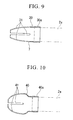
- FIG 9 shows a modified example of the embodiment according to the present invention.
- the cap 7 shown in FIG. 7 and FIG. 8 is formed in a tapered shape that gradually narrows from the proximal end portion 7a that is attached to the distal end of the insertion portion 2a of the endoscope 2 to the distal end portion, however, the cap 7 shown here has a tapered, curved shape in which the reduction ratio gradually increases from the proximal end 30a to the distal end portion. Slots 31 for engaging the wires for incision are formed in this cap 30 so as to extend along the axis.
- FIG 10 shows another modified example of the embodiment according to the present invention.
- a cap 40 shown here has a curved shape that bulges outward once from a proximal end portion 40a that is attached to the distal end of the insertion portion 2a of the endoscope, and then tapers so that the reduction ratio gradually increases toward the distal end portion. Also, Slots 41 for engaging the wire for incision are formed in this cap 40 so as to extend along the axis. When the cap 40 of this modified example is used, it is possible to widely secure the field of vision of the endoscope. Also, the cap 40 with a large maximum diameter is obtained.
- FIG 11A and FIG. 11B show the main portions of a second embodiment according to the present invention.
- FIG. 11A is a sectional view that shows distal ends of an endoscope and overtube in a state in which the endoscope is inserted in the overtube
- FIG 11B is a side view of the distal end of the overtube.
- an overtube 50 that covers the insertion portion 2a of the endoscope instead of a cap is provided. Slots 51 (engagement portion) that extend in the axial direction of this overtube 50 are formed at the distal end of the overtube 50.
- the wires 5 for incision are inserted and engaged by the slots 51.
- a conductive wire that serves as an incision knife is illustrated, but is not limited thereto, and another treatment tool may be employed. Provided it is one that projects outward in the radial direction from the sheath, it can be applied to the endoscope treatment system of the present invention regardless of whether it is provided in a fixed manner or in a manner capable of protruding and retreating from the sheath.
- slots provided in the cap or the like are used when engaging the projection portions (wires) that project from the sheath to the outside in the radial direction in the cap or overtube, but the present invention is not limited thereto.
- the projection portions engage with protrusions or depressions provided in the cap or overtube.
- the engagement portions that engage the projection portions are provided in the cap or the overtube, but the present invention is not limited thereto.
- the engagement portions may be provided in another member, for example a transparent hood that is attached to the distal end of the insertion portion of the endoscope.
- the bottom line is, the engagement portions that engage the projection portions need only be provided near the channel of the endoscope.
Landscapes
- Health & Medical Sciences (AREA)
- Life Sciences & Earth Sciences (AREA)
- Surgery (AREA)
- Animal Behavior & Ethology (AREA)
- Public Health (AREA)
- Engineering & Computer Science (AREA)
- Biomedical Technology (AREA)
- Heart & Thoracic Surgery (AREA)
- Medical Informatics (AREA)
- Molecular Biology (AREA)
- Veterinary Medicine (AREA)
- General Health & Medical Sciences (AREA)
- Nuclear Medicine, Radiotherapy & Molecular Imaging (AREA)
- Physics & Mathematics (AREA)
- Biophysics (AREA)
- Optics & Photonics (AREA)
- Pathology (AREA)
- Radiology & Medical Imaging (AREA)
- Vascular Medicine (AREA)
- Surgical Instruments (AREA)
- Endoscopes (AREA)
Abstract
Description
- The present invention relates to an endoscope treatment system that uses in combination with an endoscope, a treatment tool that is inserted in a channel of this endoscope, and an overtube that covers an insertion portion of the endoscope or a cap for the endoscope and the like.
- Conventionally, as a treatment tool that is used in combination with an endoscope, for example a treatment tool for incising a living tissue, there is known one that houses a wire that forms a knife portion in a flexible sheath, or disposes it along the outer surface of the peripheral wall of a flexible sheath, and when actually incising the living tissue, causes a portion of the wire to expand in diameter so as to greatly project to the outside of the flexible sheath, and in this state, by pressing the wire against the required portion of the living tissue that is to be incised while passing a high-frequency current through the wire, thereby making an incision (for example, refer to Published Japanese translation No.
H8-509894 of PCT 2004-73582 - In a related manner, in a conventional treatment tool that performs a diameter expansion operation on a wire when making an incision, when greatly expanding in diameter a portion of the wire when making an incision, the wire twists or bends, and so cannot be expanded in diameter to the desired shape, and due to this, the problem arises of the incision direction not being stable.
- In particular, there has been the risk of a procedure not being completed due to the wire collapsing when accompanying the rotation operation of the wire.
- The present invention was achieved in view of the above circumstances, and has as its object to provide an endoscope treatment system that is capable of maintaining the desired shape without twisting or bending of a projection portion (treatment portion) that projects outward in the radial direction from a sheath such as a wire for incision and without the projection portion collapsing inadvertently when being subjected to rotation control.
- The endoscope treatment system according to a first aspect of the present invention includes: an endoscope; and a treatment tool that has a sheath that is inserted in a channel of an insertion portion of the endoscope, in which projection portions that project outward from the sheath in the radial direction are provided, and engagement portions that engage the projection portions are provided near the channel of the endoscope.
- According to this endoscope treatment system, since the projection portions that project outward from the sheath in the radial direction are made to be engaged by the engagement portions that are provided near the channel of the endoscope, it is possible to obviate an occurrence of twisting or bending of the projection portions by shifting from the radial direction, and possible to hold the projection portions in the desired shape.
- The endoscope treatment system according to a second aspect of the present invention includes: an endoscope; a cap that is attached to the distal end of an insertion portion of the endoscope in a non-rotatable manner with respect to the insertion portion; and a treatment tool that has a sheath that is inserted in a channel of the insertion portion of the endoscope, in which projection portions that project outward from the sheath in the radial direction are provided, and engagement portions that engage the projection portions are provided in the cap.
- According to this endoscope treatment system, since the projection portions that project outward from the sheath in the radial direction are made to be engaged by the cap of the endoscope, it is possible to obviate an occurrence of twisting or bending of the projection portions by shifting from the radial direction. Also, for example, in the state of the insertion portion of the endoscope being inserted into a body cavity, when the insertion portion of this endoscope is rotated, the cap that is attached to the distal end of the insertion portion integrally rotates, and moreover the projection portions that are engaged by this cap also rotate integrally. That is, since it is possible to make the projection portions that project outward from the sheath in the radial direction integrally rotate with the cap of the endoscope, it is possible to prevent the projection portions from suddenly falling when rotating.
- The endoscope treatment system according to a third aspect of the present invention includes: an endoscope; an overtube that covers an insertion portion of the endoscope, and a sheath that is inserted in a channel of the insertion portion of the endoscope, in which projection portions that project outward from the sheath in the radial direction are provided, and engagement portions that engage the projection portions are provided in the distal end of the overtube.
- According to this endoscope treatment system, since the projection portions that project outward from the sheath in the radial direction are made to be engaged by the overtube, it is possible to obviate an occurrence of twisting or bending of the projection portions by shifting from the radial direction. Also, when for example rotating the overtube about its axial line, it is possible to also cause the projection portions that are engaged at the distal end of this overtube via the engagement portions to integrally rotate. That is, it is possible to rotate the projection portions integrally with the overtube while engaging the projection portions at the outer portions in the radial direction thereof, and therewith it is possible to stably rotate the projection portions.
- Also, in the endoscope treatment system according to the present invention, it is preferable that the engagement portions be slots that engage the projection portions in an inserted state.
- In this case, to engage the projection portions in the slots, it is sufficient to simply insert the projection portions in the slots, and the engagement operation of the projection portions becomes simple. Also, it is sufficient to simply form slots as engagement portions, and the processing of the cap is simplified.
- Also, in the endoscope treatment system according to the present invention, it is preferable that the projection portions and the engagement portions rotate in conjunction with the rotation operation of the insertion portion of the endoscope.
- In this case, when the insertion portion of the endoscope rotates, the projection portions and the engagement portions rotate in conjunction with the rotation operation of this insertion portion. In this way, to rotate the projection portions, it is sufficient to simply rotate the insertion portion of the endoscope, and the rotation operation of the projection portions is simplified. Also, when observing the image of the endoscope on a display, the projection portions are disposed near a predetermined position on the screen, and so position of the projection portions is easily confirmed.
- Also, in the endoscope treatment system according to the present invention, it is preferable that the projection portions freely project and retract.
- In this case, for example when inserting the endoscope and treatment tool in a body cavity, the projection portions are placed in a contracted state without projecting outward from the sheath in the radial direction. After being inserted to the predetermined position in the body cavity, when the treatment is performed, the projections portions are projected outward in the radial direction and are engaged in the engagement portions of the cap or the overtube. In this way, it is possible to use the projection portions by causing them to project outward in the radial direction as necessary, and so the operation when inserting them in the body cavity becomes easy.
- Also, in the endoscope treatment system according to the present invention, it is preferable that the projection portions be conductive wires to which high-frequency electricity is supplied.
- In this case, it is possible to utilize the conductive wires as an incision knife.
- Also, in the endoscope treatment system according to the present invention, it is preferable that the cap be transparent.
- In this case, even in the case of attaching the cap to the distal end of the endoscope, a procedure that uses the endoscope is not affected, with no blocking of the field of view of the endoscope by this cap.
- Also, in the endoscope treatment system according to the present invention, it is preferable that the cap be formed in a tapered shape that gradually narrows toward its distal end portion.
- In this case, since the tapered portion at the distal end of the cap functions as a guide portion when being inserted in the body cavity, insertion becomes easy. Also, by providing the engagement portions along the tapered shape, it is possible to change the radius of the engagement position corresponding to the projection portion. That is, in the case of the engagement position of the engagement portion to the projection portion being at the distal end side of the cap, it is possible to engage a comparatively smaller radius of the projection portion, and on the contrary in the case of being engaged at the proximal end side of the cap, it is possible to engage a comparatively larger radius of the projection portion.
- According to the present invention, since the projection portions that project outward from the sheath in the radial direction are engaged at the cap or overtube, it is possible to obviate an occurrence of twisting or bending of the projection portion by shifting from the radial direction. Also, when for example rotating the endoscope or overtube about its axial line, it is possible to also cause the projection portions that are engaged at the distal end of the cap provided at the distal end of the endoscope or the distal end of the overtube via the engagement portions to integrally rotate, and for this reason it is possible to stably rotate the projection portions. In addition, in the case of providing the incising portion at the distal end of the overtube, the incision operation is simplified due to large rotary torque being obtained.
-
-
FIG 1 is a perspective view that shows an endoscope treatment system of a first embodiment of the present invention. -
FIG 2 is a side view that shows a distal end portion of the endoscope treatment system. -
FIG 3 is a side view that shows the state of incising a narrow portion of an esophagus by the endoscope treatment system. -
FIG 4 is a sectional view that shows an internal construction of a distal end portion of a flexible sheath that is used in the endoscope treatment system. -
FIG 5A to FIG 5D are front views that show arrangement examples of exposed portions of wires that are used in the endoscope treatment system, andFIG 5E is a front view of a reference example of the exposed portions of the wires that are used for comparison with the present invention. -
FIG 6A is an exploded side view of an operation portion that is used in the endoscope treatment system, andFIG. 6B is a side view of the operation portion that is used in the treatment tool. -
FIG 7 is a sectional view of a cap that is used in the endoscope treatment system. -
FIG 8 is a front view of the cap that is used in the endoscope treatment system. -
FIG 9 is a sectional view that shows a modified example of a cap that is used in the endoscope treatment system of the first embodiment of the present invention. -
FIG. 10 is a sectional view that shows another modified example of a cap that is used in the endoscope treatment system of the first embodiment of the present invention. -
FIG 11A and FIG. 11B show main portions of an endoscope treatment system of a second embodiment of the present invention, withFIG 11A being a partial sectional side view that shows a structure of a distal end of an overtube and a distal end of an endoscope, andFIG 11B being a side view of the distal end of the overtube. - Hereinbelow, the embodiments of the present invention will be described.
-
FIG 1 to FIG 8 show an embodiment of an endoscope treatment system according to the present invention. Among these drawings,FIG 1 is an overall perspective view of an endoscope treatment system that shows the state of a treatment tool incorporated in an endoscope with a distal end cap,FIG 2 is a side view that shows the distal end portion of the endoscope treatment system, andFIG. 3 is a side view that shows the state of incising a narrow portion of an esophagus by the endoscope treatment system. - The endoscope treatment system of this embodiment is provided with an
endoscope 2, acap 7 that is attached to the distal end of aninsertion portion 2a of theendoscope 2 in a non-rotatable manner with respect to theinsertion portion 2a, and atreatment tool 1 for incision that has aflexible sheath 3 that is inserted in achannel 2b of theinsertion portion 2a of theendoscope 2. - The treatment tool for
incision 1 is used by being incorporated in theendoscope 2 as shown inFIG 1 . Thetreatment tool 1, as shown inFIG. 1 andFIG. 2 , is provided with the flexible sheath 3 (sheath) that is inserted into thechannel 2b formed in theinsertion portion 2a of anendoscope 2, a plurality of wires 5 (projection portions) that are inserted in theflexible sheath 3, and anoperation portion 6 that is connected to one end of thewires 5. Theflexible sheath 3 is made of, for example, a coil sheath, has flexibility, and has an insertion hole 3a that extends along the axis in the interior. - The
wires 5 are respectively inserted in firstwire insertion holes 4a that are provided at the distal end portion of the flexible sheath and secondwire insertion holes 4b that are provided further to the distal end side of the flexible sheath than the firstwire insertion holes 4a. Thereby, a portion of thewires 5 becomes wire exposedportions 10 by being exposed outward of theflexible sheath 3. By relatively advancing and retracting theoperation portion 6 in the longitudinal direction of thewires 5 with respect to theflexible sheath 3, the length of the exposedportions 10 of the wires that are exposed outward of theflexible sheath 3 is adjusted. - Note that here the side at which the
operation portion 6 is disposed in thetreatment tool 1 is referred to as the proximal end side, and the opposite side is referred to as the distal end side. - Here, the first
wire insertion holes 4a and the secondwire insertion holes 4b that are formed in theflexible sheath 3 and through which the plurality ofwires 5 are inserted are formed for eachwire 5. That is, the firstwire insertion holes 4a and the secondwire insertion holes 4b are formed in the same number as that of thewires 5. Here, the fistwire insertion holes 4a are formed at the same position in the longitudinal direction of theflexible sheath 3, and the secondwire insertion holes 4b are formed at the same position in the longitudinal direction of theflexible sheath 3. Also, these first and secondwire insertion holes - The plurality of
wires 5, as shown inFIG. 4 , each have a proximal endside insertion portion 11 that passes through the interior space of theflexible sheath 3 further to the proximal end side than the firstwire insertion hole 4a, the exposedportion 10 that extends from this proximal endside insertion portion 11 toward the distal end side, passes through the firstwire insertion hole 4a, and is exposed outward of theflexible sheath 3, a distal endside insertion portion 12 that extends from this exposedportion 10 toward the distal end, passes through the secondwire insertion hole 4b, and again enters into the interior space of theflexible sheath 3, and abend portion 13 that is provided at the end portion of the exposedportion 10. side of this distal endside insertion portion 12 and bends thewire 5 from the direction of entering into the interior space of theflexible sheath 3 via the secondwire insertion hole 4b to the axial direction of theflexible sheath 3. Also, the plurality ofwires 5 are bundled into one by a bindingmember 14 at a position further to the distal end side than thebend portion 13. - The
wires 5 have flexibility, and when theoperation portion 6 is operated to be advanced or retreated in the longitudinal direction of the wires, as shown inFIG. 2 and FIG. 3 , the shape of the exposedportions 10 is deformed so as to swell outward or contract inward. Also, thewires 5 have electrical conductivity, and so by supplying high-frequency electrical current, the exposedportions 10 function as a knife portion that incises a living tissue (specifically, an inner wall of the esophagus). - The binding
member 14 has a hole in the center, and thewires 5 are inserted into this hole. Thesewires 5 are engaged and fixed to the bindingmember 14 by the frictional force due to the elasticity of the binding member itself or an adhesive. - The binding
member 14 is formed in a tapered shape in which the distal end side narrows, and made of a material that has suitable elasticity and heat resistance. Also, the maximum diameter of the bindingmember 14 is set to a value that is slightly larger than the inner diameter of theflexible sheath 3 such that the bindingmember 14 is engaged with the inner surface of theflexible sheath 3 with a suitable frictional force. - A
balloon 15 which is capable of attaining a greater diameter than the diameter of theflexible sheath 3 is attached further to the distal end side than the wire exposedportions 10. Theballoon 15 is connected to an air supply source via an air pipe (not illustrated) that is disposed in theflexible sheath 3, and so when air is supplied from this air pipe to the interior, as shown inFIG. 3 , it swells toward the outside. - As shown in
FIG 5A to FIG 5D , the number of thewires 5 may be 4, 3, 2, or 8, or a plurality other than that. However, as shown in these drawings, the wire exposedportions 10 are disposed in an equiangular arrangement in the circumferential direction so as to form a radial pattern. - A heat-resistant coating is applied to the
wire 5 near the firstwire insertion holes 4a and the secondwire insertion holes 4b in order that the heat of thewires 5 is not directly transferred tostabilizers 16 andcap 7 described below. - As shown in
FIG 4 , in theflexible sheath 3, thestabilizers 16 are provided near the first and secondwire insertion holes portions 10 of thewires 5 are expanded in diameter, thestabilizers 16 restrict the movement of thewires 5 so that thewires 5 extend in the normal line direction with respect to the outside surface of theflexible sheath 3 without twisting to the right and left, that is, so as not to shift from the radial direction of theflexible sheath 3. - Various types of the
stabilizers 16 are conceivable. For example, as shown inFIG. 4 ,stabilizers flexible sheath 3 so as to be mutually symmetrical in correspondence with the first and secondwire insertion holes - The proximal
end side stabilizer 16a corresponding to the firstwire insertion holes 4a has adisk portion 17 and fourprojections 18 having a fan shaped cross-sectional that extend in a direction perpendicular to thedisk portion 17 from one side surface of thedisk portion 17, with theprojections 18 being disposed and fixed so as to face the proximal end side. Also, the distalend side stabilizer 16b corresponding to the secondwire insertion holes 4b has adisk portion 17 and fourprojections 18 having a fan shaped cross-sectional that extends in a direction perpendicular to thedisk portion 17 from one side surface of thedisk portion 17, with theprojections 18 being disposed and fixed so as to face the distal end side. - Also, wire guide slots are respectively formed between the
projections 18. Thestabilizers flexible sheath 3 so that the wire guide slots of the proximalend side stabilizer 16a and the wire guide slots of the distalend side stabilizer 16b mutually have the same angle positions and correspond to the first and secondwire insertion holes wires 5. - Note that these
stabilizers -
FIG. 6A is an exploded view of theoperation portion 6, andFIG. 6B is a side view of theoperation portion 6. As shown in these drawings, the proximal end of theflexible sheath 3 is connected to an operation portionmain body 23. A guide slot which is not illustrated is formed in the axial direction in the intermediate portion of the operation portionmain body 23, and aslide portion 24 that slides along the guide slot is mounted on the operating sectionmain body 23. Aterminal supporting portion 25 is integrally provided at theslide portion 24, and anelectrode terminal 26 is attached to thisterminal supporting portion 25. The proximal ends of thewires 5 are connected to theelectrode terminal 26, and a connection terminal (not illustrated) that extends from a high-frequency power source is capable of being connected to thiselectrode terminal 26. - The plurality of
wires 5 may individually extend toward the proximal end to be connected to theelectrode terminal 26. The plurality ofwires 5 may be gathered into one at the proximal end side and be connected to theelectrode terminal 26. - Also, a
scale 27 is affixed to the operation portionmain body 23, and with thisscale 27, the amount of movement of theslide portion 24, and as a result, a guide of the clearance L of the exposedportions 10 of thewires 5 from the axis of theflexible sheath 3 can be displayed (refer toFIG 4 ). - Here, when the
slide portion 24 is advanced or retreated in the longitudinal direction of thewires 5, the proximal end side of thewires 5 that is connected to theelectrode terminal 26 that moves integrally with theslide portion 24 moves in the same direction. The movement of thesewires 5 is in turn transmitted to the distal end side, and as a result the length of the exposedportions 10 of the wires is adjusted as shown inFIG. 4 . That is, the operation portionmain body 23 and theslide portion 24 constitute theoperation portion 6 that adjusts the length of the exposedportions 10 of the wires by advancing or retracting thewires 5. - As shown in
FIG 7 and FIG 8 , thecap 7 is attached to the distal end of theendoscope 2 in a non-rotatable manner. Methods of attaching thecap 7 to the distal end of theendoscope 2 may include one that employs a screw or one that uses a concavo-convex fitting. However, it is necessary that thecap 7 is attached to theendoscope 2 in a non-rotatable manner. Thecap 7 is formed in a tapered shape that gradually narrows from aproximal end portion 7a that is attached to the distal end of theendoscope 2 to the distal end portion. - Slots 8 (engagement portions) that cause the
wires 5 of thetreatment tool 1 to engage are formed in a taperedportion 7b of the distal end of thecap 7 so as to extend along the axis of thecap 7 to the distal end thereof. Theslots 8 are provided in the same number as that of thewire 5, that is, in the case of there being four of thewires 5, fourslots 8 are provided. The width dimension w of each of theslots 8 is set so as to be 2 to 7 times as large as the diameter of thewire 5, and more preferably 3 to 6 times. When the width dimension of theslot 8 is too narrow, the engagement of the wire by theslot 8 is hindered. Also, when the width dimension of theslot 8 is too wide, the function of guiding thewire 5 by theslot 8 is impaired. - Also, the
cap 7 is preferably made of a transparent material. With thiscap 7, a procedure that uses the endoscope is not affected with no blocking of the field of view of the endoscope. - Note that an
opening 9 that allows passage of thesheath 2 is formed in the center of the distal end of thecap 7. - Next, the procedure of incising a narrow portion of an esophagus using the endoscope treatment system of the above constitution will be described.
- First, as shown in
FIG 2 , the exposedportions 10 of the wires are put into a state of their most contracted diameter, and theballoon 15 is put in a contracted state. Then, theinsertion portion 2a of theendoscope 2 with thecap 7 attached to the distal end thereof in advance is inserted into the mouth and guided to the interior of the esophagus S, with the narrow portion Sa being confirmed by endoscopic images. After confirming the location of the narrow portion Sa, theflexible sheath 3 is inserted in thechannel 2b of theendoscope 2. Then, while confirming with the endoscopic images, theflexible sheath 3 is projected from the distal end of theinsertion portion 2a. - Then, as shown in
FIG. 2 , while performing confirmation with endoscopic images, the exposedportions 10 of the wires are made to face the narrow portion Sa of the esophagus. Adjustment of the position of the exposedportions 10 of the wires and the narrow portion Sa may be performed by adjusting the insertion amount of theinsertion portion 2a of the endoscope while maintaining the relative positions of theendoscope 2 and thetreatment tool 1 constant. Alternatively, the insertion amount of theinsertion portion 2a of the endoscope may be left as is and the projection amount of theflexible sheath 3 from the distal end of theinsertion portion 2a may be adjusted. - After the exposed
portions 10 of the wires are made to oppose the narrow portion Sa of the esophagus in the manner, theslider portion 24 of theoperation portion 6 is made to advance in the longitudinal direction of the wires to cause the exposedportion 10 of each wire to expand in diameter as shown inFIG. 3 . Simultaneously with this, air is supplied via the air pipe (not shown) to inflate theballoon 15. - Here, when the
slider portion 24 is made to advance in the longitudinal direction of the wires, the proximal end side of thewires 5 that are connected to theslider portion 24 move in the same direction, and the movement of thewires 5 is in turn transmitted to the distal end side, and as a result the distal end side of thewires 5 receives the force to be moved forward. At this time, since thebend portion 13 is provided at the distal endside insertion portion 12 of thewires 5, by thisbend portion 13, the transmitted force that causes thewires 5 to move forward is divided. That is, at the distal end side of thewires 5, thebend portion 13 functions as a stopper, and forward movement of thewires 5 further to the front side than thebend portion 13 is restricted. In addition, in this embodiment, forward movement of thewires 5 further to the front side than thebend portion 13 is restricted by the bindingmember 14 that is supplementarily provided. As a result of these, relative movement of the proximal end side of thewires 5 with respect to theflexible sheath 3 is integrated at the exposedportions 10 of the wires that are exposed outward of theflexible sheath 3, and as shown inFIG. 3 , the exposedportions 10 of the wires are expanded in diameter to the desired shape. - Here, the operation of expanding the diameter of the exposed
portions 10 of the wires by theoperation portion 6 and the operation of inflating theballoon 15 may be interrelated and simultaneously performed. - For example, when advancing the
slider portion 24 of thecontrol portion 6, the movement of theslider portion 24 may be detected by a sensor, and based on this detection result, an air supply means which is not illustrated may be activated to supply the predetermined amount of air to theballoon 15 to inflate theballoon 15. - Also, the
stabilizers 16 are provided in the vicinity of the firstwire insertion holes 4a and the secondwire insertion holes 4b of theflexible sheath 3. Because thewires 5 are guided by the wire guide slots of thestabilizers 16, as shown inFIG 5A to FIG. 5D , the exposedportions 10 of thewires 5 expand in diameter so as to extend in the normal line direction with respect to the outside surface of theflexible sheath 3. Accordingly, as shown inFIG. 5E , the exposedportions 10 of thewires 5 expand in diameter while being disposed in an equiangular arrangement in the circumferential direction so as to form a radial pattern without twisting to the right and left. As described below, this state is similarly maintained when rotating thistreatment tool 1 to incise the narrow portion Sa of the esophagus. - Also, when the exposed
portions 10 of thewires 5 are expanded in diameter to the desired shape, the clearance L of the exposedportions 10 of thewires 5 from the axis of theflexible sheath 3 can be accurately found with thescale 27 that is attached to the operation portionmain body 23. For this reason, during operation of theoperation portion 6, it is possible to prevent the depth of incision into the narrow portion Sa of the esophagus by the exposedportions 10 of thewires 5 from becoming deeper than required beforehand. - Also, when expanding the diameter of the exposed
portions 10 of thewires 5, thesewires 5 that have been expanded in diameter are inserted and engaged in theslots 8 of thecap 7. Note that in the case of the positions of thewires 5 and theslots 8 being shifted in the circumferential direction, by rotating thetreatment tool 1 relative to theinsertion portion 2a of theendoscope 2 so that thewires 5 of thetreatment tool 1 arrive at the positions corresponding to theslots 8, thewires 5 will naturally be inserted and engaged in theslots 8. - Note that, to inserte and engage the
wires 5 in theslots 8 as described above, from the state shown inFIG. 2 , after expanding the diameter of the exposedportions 10 of the wires, thecap 7 may be advanced integrally with theinsertion portion 2a relative to thetreatment tool 1. Alternatively, by disposing thecap 7 in a position that enables thewires 5 to be engaged in theslots 8 in advance, the exposedportions 10 of thewires 5 may be then expanded in diameter to be engaged. - Expansion of the diameter of the exposed
portions 10 of thewires 5 by operation of theoperation portion 6 is performed while passing high-frequency current through thewires 5. Accordingly, when the exposedportions 10 of thewires 5 are expanding in diameter, incision of the interior of the narrow portion Sa of the esophagus to the predetermined depth is performed. Then, while flowing high-frequency current to thewires 5, thetreatment tool 1 is rotated with theinsertion portion 2a of theendoscope 2. At this time, since all thewires 5 integrally rotate with thecap 7 while being guided by theslots 8 of thecap 7, when incising the living tissue, even if a reactive force is received from the living tissue, the exposedportions 10 of thewires 5 stably rotate while being disposed in a radial shape without thewires 5 shifting from the radial direction to twist or bend or collapse in the circumferential direction. Thereby, it is possible to quickly make an incision in the narrow portion Sa of the esophagus. - In this embodiment, since the
balloon 15 with the expanded diameter is disposed at the predetermined position in the distal end side of the exposedportions 10 of thewires 5, even in the case of a force in the pull-out direction being suddenly applied during rotation, theballoon 15 that has expanded in diameter functions as an anchor, and so thetreatment tool 1 does not shift to the proximal end side. That is, the exposedportions 10 of thewires 5 are held at their respective positions facing the narrow portion Sa of the esophagus. - Also, as stated above, the
balloon 15 that has expanded in diameter is at a predetermined position at the distal end side of the exposedportions 10 of thewires 5, and, with thisballoon 15, the distal end portion of theflexible sheath 3 is held at approximately the center with respect to the esophagus. Accordingly, when thetreatment tool 1 is rotated, it is possible to prevent unexpected swinging of the distal end portion of theflexible sheath 3 including the exposedportions 10 of thewires 5. As a result, it is possible to perform smooth incision of the narrow portion Sa of the esophagus with the exposedportions 10 of thewires 5. - After making the incision, along with contracting the
balloon 15, the exposedportions 10 of thewires 5 are contracted by operation of theoperation portion 6, and in this state, the distal end portion of thetreatment tool 1 is completely housed inside the channel of theendoscope 2, and thistreatment tool 1 is pulled out from the body with theendoscope 2. - Note that in the above first embodiment, the
balloon 15 and thestabilizers 16 are provided, but these members are not necessarily required, and may be omitted. -
FIG 9 shows a modified example of the embodiment according to the present invention. - The
cap 7 shown inFIG. 7 and FIG. 8 is formed in a tapered shape that gradually narrows from theproximal end portion 7a that is attached to the distal end of theinsertion portion 2a of theendoscope 2 to the distal end portion, however, thecap 7 shown here has a tapered, curved shape in which the reduction ratio gradually increases from theproximal end 30a to the distal end portion.Slots 31 for engaging the wires for incision are formed in thiscap 30 so as to extend along the axis. -
FIG 10 shows another modified example of the embodiment according to the present invention. - A
cap 40 shown here has a curved shape that bulges outward once from aproximal end portion 40a that is attached to the distal end of theinsertion portion 2a of the endoscope, and then tapers so that the reduction ratio gradually increases toward the distal end portion. Also,Slots 41 for engaging the wire for incision are formed in thiscap 40 so as to extend along the axis. When thecap 40 of this modified example is used, it is possible to widely secure the field of vision of the endoscope. Also, thecap 40 with a large maximum diameter is obtained. -
FIG 11A and FIG. 11B show the main portions of a second embodiment according to the present invention.FIG. 11A is a sectional view that shows distal ends of an endoscope and overtube in a state in which the endoscope is inserted in the overtube, andFIG 11B is a side view of the distal end of the overtube. - Note that in order to simplify the description, in this second embodiment, constituent elements that are the same as those used in the first embodiment shall be assigned the same reference numerals, and descriptions there of will be omitted.
- In this second embodiment, an
overtube 50 that covers theinsertion portion 2a of the endoscope instead of a cap is provided. Slots 51 (engagement portion) that extend in the axial direction of thisovertube 50 are formed at the distal end of theovertube 50. - The
wires 5 for incision are inserted and engaged by theslots 51. - With this endoscope treatment system of the second embodiment, when incising a narrow portion of an esophagus, for example, first in the state of the
wires 5 for incision being engaged in theslot 51 of theovertube 50, thewires 5 for incision are arranged at a position facing the narrow portion. Then, theovertube 50 is made to rotate about the axis. Thereby, since thewires 5 for incision rotate integrally with theovertube 50 while being guided by theslots 51 of theovertube 50, even in the case of receiving a reactive force from the living tissue, the exposedportions 10 of thewires 5 stably rotate while being disposed in a radial shape without thewires 5 shifting from the radial direction to twist or bend or collapse in the circumferential direction. Thereby, it is possible to quickly make an incision in the narrow portion Sa of the esophagus. - Note that the present invention is not limited to the above embodiments, and design modified examples can be made in the scope of not departing from the spirit of the invention.
- In the first and second embodiments, as a member that is made to be engaged in the slots of a cap or overtube, a conductive wire that serves as an incision knife is illustrated, but is not limited thereto, and another treatment tool may be employed. Provided it is one that projects outward in the radial direction from the sheath, it can be applied to the endoscope treatment system of the present invention regardless of whether it is provided in a fixed manner or in a manner capable of protruding and retreating from the sheath.
- Also, in the first and second embodiments, slots provided in the cap or the like are used when engaging the projection portions (wires) that project from the sheath to the outside in the radial direction in the cap or overtube, but the present invention is not limited thereto. For example, it is possible to make the projection portions engage with protrusions or depressions provided in the cap or overtube.
- Also, in the first and second embodiments, the engagement portions that engage the projection portions are provided in the cap or the overtube, but the present invention is not limited thereto. The engagement portions may be provided in another member, for example a transparent hood that is attached to the distal end of the insertion portion of the endoscope. The bottom line is, the engagement portions that engage the projection portions need only be provided near the channel of the endoscope.
- While preferred embodiments of the invention have been described and illustrated above, it should be understood that these are exemplary of the invention and are not to be considered as limiting. Additions, omissions, substitutions, and other modified examples can be made without departing from the spirit or scope of the present invention. Accordingly, the invention is not to be considered as being limited by the foregoing description, and is only limited by the scope of the appended claims.
Claims (9)
- An endoscope treatment system comprising:an endoscope (2); anda treatment tool (1) that has a sheath (3) that is inserted in a channel of an insertion portion of the endoscope;
wherein projection portions (5) that project outward from the sheath in the radial direction are provided, andengagement portions (8) that engage the projection portions are provided near the channel of the endoscope. - An endoscope treatment system comprising:an endoscope (2);a cap (7) that is attached to the distal end of an insertion portion of the endoscope in a non-rotatable manner with respect to the insertion portion; anda treatment tool (1) that has a sheath (3) that is inserted in a channel of the insertion portion of the endoscope;wherein projection portions (5) that project outward from the sheath in the radial direction are provided, and engagement portions (8) that engage the projection portions are provided in the cap.
- An endoscope treatment system comprising:an endoscope (2);an overtube (50) that covers an insertion portion of the endoscope; anda treatment tool (1) that has a sheath (3) that is inserted in a channel of the insertion portion of the endoscope;wherein projection portions (5) that project outward from the sheath in the radial direction are provided, and engagement portions (51) that engage the projection portions are provided in the distal end of the overtube.
- The endoscope treatment system according to any one of claims 1 to 3, wherein the engagement portions are slots that engage the projection portions in an inserted state.
- The endoscope treatment system according to any one of claims 1 to 4, wherein the projection portions and the engagement portions rotate in conjunction with the rotation operation of the insertion portion of the endoscope.
- The endoscope treatment system according to any one of claims 1 to 5, wherein the projection portions freely project and retract.
- The endoscope treatment system according to any one of claims 1 to 6, wherein the projection portions are conductive wires to which high-frequency electricity is supplied.
- The endoscope treatment system according to claim 2, wherein the cap is transparent.
- The endoscope treatment system according to either claim 2 or 8, wherein the cap is formed in a tapered shape that gradually narrows toward its distal end portion.
Applications Claiming Priority (1)
| Application Number | Priority Date | Filing Date | Title |
|---|---|---|---|
| JP2007307687A JP5284628B2 (en) | 2007-11-28 | 2007-11-28 | Endoscope treatment system |
Publications (3)
| Publication Number | Publication Date |
|---|---|
| EP2065003A2 true EP2065003A2 (en) | 2009-06-03 |
| EP2065003A3 EP2065003A3 (en) | 2009-06-17 |
| EP2065003B1 EP2065003B1 (en) | 2016-08-10 |
Family
ID=40483426
Family Applications (1)
| Application Number | Title | Priority Date | Filing Date |
|---|---|---|---|
| EP08020533.9A Not-in-force EP2065003B1 (en) | 2007-11-28 | 2008-11-26 | Endoscope treatment system |
Country Status (3)
| Country | Link |
|---|---|
| US (1) | US8491463B2 (en) |
| EP (1) | EP2065003B1 (en) |
| JP (1) | JP5284628B2 (en) |
Families Citing this family (23)
| Publication number | Priority date | Publication date | Assignee | Title |
|---|---|---|---|---|
| US20060068428A1 (en) * | 2003-11-03 | 2006-03-30 | Duke University | Identification of genetic markers associated with parkinson disease |
| US8182422B2 (en) | 2005-12-13 | 2012-05-22 | Avantis Medical Systems, Inc. | Endoscope having detachable imaging device and method of using |
| US8872906B2 (en) | 2005-01-05 | 2014-10-28 | Avantis Medical Systems, Inc. | Endoscope assembly with a polarizing filter |
| US20070293720A1 (en) * | 2005-01-05 | 2007-12-20 | Avantis Medical Systems, Inc. | Endoscope assembly and method of viewing an area inside a cavity |
| US20080021274A1 (en) * | 2005-01-05 | 2008-01-24 | Avantis Medical Systems, Inc. | Endoscopic medical device with locking mechanism and method |
| US8797392B2 (en) | 2005-01-05 | 2014-08-05 | Avantis Medical Sytems, Inc. | Endoscope assembly with a polarizing filter |
| US8289381B2 (en) | 2005-01-05 | 2012-10-16 | Avantis Medical Systems, Inc. | Endoscope with an imaging catheter assembly and method of configuring an endoscope |
| US8235887B2 (en) | 2006-01-23 | 2012-08-07 | Avantis Medical Systems, Inc. | Endoscope assembly with retroscope |
| US8287446B2 (en) | 2006-04-18 | 2012-10-16 | Avantis Medical Systems, Inc. | Vibratory device, endoscope having such a device, method for configuring an endoscope, and method of reducing looping of an endoscope |
| JP2009537283A (en) | 2006-05-19 | 2009-10-29 | アヴァンティス メディカル システムズ インコーポレイテッド | Apparatus and method for reducing the effects of video artifacts |
| US8064666B2 (en) | 2007-04-10 | 2011-11-22 | Avantis Medical Systems, Inc. | Method and device for examining or imaging an interior surface of a cavity |
| US7985176B1 (en) | 2010-05-26 | 2011-07-26 | Coloplast A/S | Method of implanting a penile prosthesis |
| DK201070210A (en) | 2009-08-27 | 2010-11-28 | Coloplast As | Penile prosthesis cap and assembly |
| WO2011023197A1 (en) * | 2009-08-27 | 2011-03-03 | Coloplast A/S | Penile prosthesis cap, assembly, and implantation tool |
| ES2562264T5 (en) | 2010-05-25 | 2019-06-24 | Arc Medical Design Ltd | Cover for medical scanning device |
| JP2012115317A (en) * | 2010-11-29 | 2012-06-21 | Asahi Intecc Co Ltd | Medical treatment instrument |
| US9731098B2 (en) | 2013-03-13 | 2017-08-15 | The Spectranetics Corporation | Wire centering sheath and method |
| US9855144B2 (en) | 2015-09-09 | 2018-01-02 | Coloplast A/S | Penile prosthetic with an insertion tool contained inside an inflatable bladder |
| EP3150174B1 (en) | 2015-09-30 | 2021-08-11 | Coloplast A/S | A penile prosthetic with an insertion sleeve attachable to an inflatable bladder |
| SG11201810637VA (en) * | 2016-06-01 | 2018-12-28 | Endomaster Pte Ltd | Endoscopy system components |
| EP3357458A1 (en) | 2017-02-02 | 2018-08-08 | Coloplast A/S | Inflatable penile prosthetic system |
| CN114681043A (en) * | 2020-12-31 | 2022-07-01 | 波士顿科学国际有限公司 | Medical device and related method |
| JP7626634B2 (en) * | 2021-03-11 | 2025-02-04 | 株式会社カネカ | High frequency treatment tools |
Citations (2)
| Publication number | Priority date | Publication date | Assignee | Title |
|---|---|---|---|---|
| JPH08509894A (en) | 1993-09-28 | 1996-10-22 | アメリカン・メディカル・システムズ・インコーポレーテッド | Electrosurgical equipment |
| JP2004073582A (en) | 2002-08-20 | 2004-03-11 | Olympus Corp | Biological tissue resection tool |
Family Cites Families (6)
| Publication number | Priority date | Publication date | Assignee | Title |
|---|---|---|---|---|
| JPS5727445Y2 (en) * | 1973-06-20 | 1982-06-15 | ||
| US5897487A (en) * | 1997-04-15 | 1999-04-27 | Asahi Kogaku Kogyo Kabushiki Kaisha | Front end hood for endoscope |
| US6059719A (en) * | 1997-08-06 | 2000-05-09 | Olympus Optical Co., Ltd. | Endoscope system |
| JP2002112946A (en) * | 2000-10-11 | 2002-04-16 | Olympus Optical Co Ltd | Hood for endoscope |
| EP1572263A4 (en) | 2002-11-01 | 2008-10-29 | Conmed Endoscopic Technologies | Low profile short tapered tip catheter |
| JP4391765B2 (en) * | 2002-12-02 | 2009-12-24 | オリンパス株式会社 | Endoscopic mucosal resection tool |
-
2007
- 2007-11-28 JP JP2007307687A patent/JP5284628B2/en not_active Expired - Fee Related
-
2008
- 2008-11-25 US US12/277,508 patent/US8491463B2/en not_active Expired - Fee Related
- 2008-11-26 EP EP08020533.9A patent/EP2065003B1/en not_active Not-in-force
Patent Citations (2)
| Publication number | Priority date | Publication date | Assignee | Title |
|---|---|---|---|---|
| JPH08509894A (en) | 1993-09-28 | 1996-10-22 | アメリカン・メディカル・システムズ・インコーポレーテッド | Electrosurgical equipment |
| JP2004073582A (en) | 2002-08-20 | 2004-03-11 | Olympus Corp | Biological tissue resection tool |
Also Published As
| Publication number | Publication date |
|---|---|
| EP2065003B1 (en) | 2016-08-10 |
| EP2065003A3 (en) | 2009-06-17 |
| JP2009131310A (en) | 2009-06-18 |
| JP5284628B2 (en) | 2013-09-11 |
| US8491463B2 (en) | 2013-07-23 |
| US20090137867A1 (en) | 2009-05-28 |
Similar Documents
| Publication | Publication Date | Title |
|---|---|---|
| US8491463B2 (en) | Endoscope treatment system | |
| EP1997443B1 (en) | Incision tool | |
| US8663238B2 (en) | Treatment tool | |
| JP5111931B2 (en) | Endoscopic treatment tool | |
| JP4323441B2 (en) | Endoscope | |
| US7922717B2 (en) | High-frequency treatment tool for endoscope | |
| CN101416863B (en) | Endoscopic instrument and method for manufacturing thereof | |
| JP6177021B2 (en) | Endoscope | |
| JP2002263111A (en) | Sampling tool for endoscope | |
| US12070186B2 (en) | Surgical system and expansion device | |
| JPWO2017175373A1 (en) | Flexible manipulator | |
| JP6697291B2 (en) | Endoscope bending tube | |
| EP3932461A1 (en) | Torque device | |
| EP2065004A2 (en) | Endoscopic incision system | |
| JP5137758B2 (en) | Bipolar high-frequency treatment instrument for endoscope | |
| JP4425223B2 (en) | High frequency knife for endoscope | |
| JP5191338B2 (en) | Bipolar high-frequency snare for endoscope | |
| JP5191340B2 (en) | Endoscopic treatment tool | |
| JP4996440B2 (en) | Endoscopic high-frequency treatment instrument | |
| JP2021171316A (en) | Endoscope snare | |
| JP6556347B2 (en) | MEDICAL MANIPULATOR AND METHOD OF OPERATING MEDICAL MANIPULATOR | |
| JP5137754B2 (en) | Endoscopic treatment tool | |
| JP5137727B2 (en) | Endoscope | |
| JP2014083237A (en) | Probe position control device | |
| JP3772138B2 (en) | Endoscope system |
Legal Events
| Date | Code | Title | Description |
|---|---|---|---|
| PUAI | Public reference made under article 153(3) epc to a published international application that has entered the european phase |
Free format text: ORIGINAL CODE: 0009012 |
|
| PUAL | Search report despatched |
Free format text: ORIGINAL CODE: 0009013 |
|
| AK | Designated contracting states |
Kind code of ref document: A2 Designated state(s): AT BE BG CH CY CZ DE DK EE ES FI FR GB GR HR HU IE IS IT LI LT LU LV MC MT NL NO PL PT RO SE SI SK TR |
|
| AX | Request for extension of the european patent |
Extension state: AL BA MK RS |
|
| AK | Designated contracting states |
Kind code of ref document: A3 Designated state(s): AT BE BG CH CY CZ DE DK EE ES FI FR GB GR HR HU IE IS IT LI LT LU LV MC MT NL NO PL PT RO SE SI SK TR |
|
| AX | Request for extension of the european patent |
Extension state: AL BA MK RS |
|
| RIC1 | Information provided on ipc code assigned before grant |
Ipc: A61B 17/22 20060101ALI20090508BHEP Ipc: A61B 17/32 20060101AFI20090406BHEP Ipc: A61B 1/012 20060101ALI20090508BHEP |
|
| 17P | Request for examination filed |
Effective date: 20090806 |
|
| 17Q | First examination report despatched |
Effective date: 20090901 |
|
| AKX | Designation fees paid |
Designated state(s): DE FR IE |
|
| RAP1 | Party data changed (applicant data changed or rights of an application transferred) |
Owner name: OLYMPUS CORPORATION |
|
| GRAP | Despatch of communication of intention to grant a patent |
Free format text: ORIGINAL CODE: EPIDOSNIGR1 |
|
| INTG | Intention to grant announced |
Effective date: 20151119 |
|
| GRAP | Despatch of communication of intention to grant a patent |
Free format text: ORIGINAL CODE: EPIDOSNIGR1 |
|
| INTG | Intention to grant announced |
Effective date: 20160511 |
|
| GRAS | Grant fee paid |
Free format text: ORIGINAL CODE: EPIDOSNIGR3 |
|
| GRAA | (expected) grant |
Free format text: ORIGINAL CODE: 0009210 |
|
| AK | Designated contracting states |
Kind code of ref document: B1 Designated state(s): DE FR IE |
|
| REG | Reference to a national code |
Ref country code: IE Ref legal event code: FG4D |
|
| RAP2 | Party data changed (patent owner data changed or rights of a patent transferred) |
Owner name: OLYMPUS CORPORATION |
|
| REG | Reference to a national code |
Ref country code: DE Ref legal event code: R096 Ref document number: 602008045498 Country of ref document: DE |
|
| RAP2 | Party data changed (patent owner data changed or rights of a patent transferred) |
Owner name: OLYMPUS CORPORATION |
|
| RAP2 | Party data changed (patent owner data changed or rights of a patent transferred) |
Owner name: OLYMPUS CORPORATION |
|
| REG | Reference to a national code |
Ref country code: DE Ref legal event code: R097 Ref document number: 602008045498 Country of ref document: DE |
|
| PLBE | No opposition filed within time limit |
Free format text: ORIGINAL CODE: 0009261 |
|
| STAA | Information on the status of an ep patent application or granted ep patent |
Free format text: STATUS: NO OPPOSITION FILED WITHIN TIME LIMIT |
|
| 26N | No opposition filed |
Effective date: 20170511 |
|
| REG | Reference to a national code |
Ref country code: IE Ref legal event code: MM4A |
|
| REG | Reference to a national code |
Ref country code: FR Ref legal event code: ST Effective date: 20170731 |
|
| PG25 | Lapsed in a contracting state [announced via postgrant information from national office to epo] |
Ref country code: FR Free format text: LAPSE BECAUSE OF NON-PAYMENT OF DUE FEES Effective date: 20161130 |
|
| PG25 | Lapsed in a contracting state [announced via postgrant information from national office to epo] |
Ref country code: IE Free format text: LAPSE BECAUSE OF NON-PAYMENT OF DUE FEES Effective date: 20161126 |
|
| PGFP | Annual fee paid to national office [announced via postgrant information from national office to epo] |
Ref country code: DE Payment date: 20181120 Year of fee payment: 11 |
|
| REG | Reference to a national code |
Ref country code: DE Ref legal event code: R119 Ref document number: 602008045498 Country of ref document: DE |
|
| PG25 | Lapsed in a contracting state [announced via postgrant information from national office to epo] |
Ref country code: DE Free format text: LAPSE BECAUSE OF NON-PAYMENT OF DUE FEES Effective date: 20200603 |