EP2064963A2 - A Helmet - Google Patents
A Helmet Download PDFInfo
- Publication number
- EP2064963A2 EP2064963A2 EP08253665A EP08253665A EP2064963A2 EP 2064963 A2 EP2064963 A2 EP 2064963A2 EP 08253665 A EP08253665 A EP 08253665A EP 08253665 A EP08253665 A EP 08253665A EP 2064963 A2 EP2064963 A2 EP 2064963A2
- Authority
- EP
- European Patent Office
- Prior art keywords
- helmet
- strap
- secured
- location
- wearer
- Prior art date
- Legal status (The legal status is an assumption and is not a legal conclusion. Google has not performed a legal analysis and makes no representation as to the accuracy of the status listed.)
- Granted
Links
Images

Classifications
-
- A—HUMAN NECESSITIES
- A42—HEADWEAR
- A42B—HATS; HEAD COVERINGS
- A42B3/00—Helmets; Helmet covers ; Other protective head coverings
- A42B3/04—Parts, details or accessories of helmets
- A42B3/08—Chin straps or similar retention devices
-
- A—HUMAN NECESSITIES
- A42—HEADWEAR
- A42B—HATS; HEAD COVERINGS
- A42B3/00—Helmets; Helmet covers ; Other protective head coverings
- A42B3/04—Parts, details or accessories of helmets
Definitions
- the present invention relates to a helmet and in particular, but not exclusively, to a horse riding helmet.
- Horse riding helmets have long been employed to prevent or reduce the damage caused by impacts to the heads of horse riders. They typically comprise a hard outer shell that provides structural rigidity and resistance to physical impacts and a soft inner lining. The lining has two effects, the first is to improve the comfort for the wearer of the helmet and the second is to help reduce the force transmitted to the wearer's skull from any impacts to the outer shell by reducing the maximum deceleration on impact.
- the helmet is fitted with a strap that, when fastened, holds the helmet in place and prevents it from becoming dislodged.
- the strap is formed in two halves, each being anchored securely to the outer shell by a rivet. The two strap halves depend from the sides and can be brought together and secured to one another under the wearer's chin by means of a buckle or the like.
- Each of the strap halves may be secured to the helmet at two positions, a first location to the side of the helmet and a second location at the rear.
- the strap not only serves to restrict the vertical movement relative to the wearer's head but also any slipping of the helmet on the wearer's head from side to side or front to rear.
- the present invention provides a helmet for protecting the head of a wearer comprising: a helmet body; and a strap for coupling the helmet to the head, the strap being secured to the helmet body; the strap comprising a first portion intended to pass under the chin of a wearer and a second portion joined to said first portion and intended to pass around the rear and side of a wearer's head; the first portion having an end that is secured to the helmet body at a first location and the second portion having an end that is secured to the helmet body at a second location, spaced from the first location; and a pocket in the second portion of the strap containing a resiliently deformable element.
- the resiliently deformable element serves to provide additional grip and comfort for the wearer. It may take any suitable form but in one embodiment it takes the form of an elastomeric pad such as, for example, a suction cup that has a convex side and a concave side.
- the cup may be substantially disc-shaped and may be positioned in the pocket such that the concave side faces the wearer. When the strap is tensioned against the wearer's head the cup may deform so as to apply the gripping force to the wearer's head.
- a foam pad may also be inserted in the pocket on the concave side of the cup, to enhance comfort.
- the pocket may be disposed near the end of the second part of the strap where it is secured to the helmet body. This provides the best fit for the wearer. The arrangement serves to improve the safety of the helmet.
- the strap may comprise a first portion with an end that is secured to the helmet body at a first location and a second portion with an end that is secured to the helmet at a second location (the first and second locations being different on each strap part).
- the first and second portions may be integrally connected or formed.
- the second location may be spaced from a rearmost portion of helmet body, it may be spaced from the rearmost position by a distance in the range 80 to 100mm, along the edge of the helmet body, and preferably in the range 85 to 95mm and more preferably 95mm.
- the second location may be positioned such that it subtends an angle in the range 50° to 80° to a central line that intersects the rearmost and foremost locations of the helmet.
- the strap may comprise two parts, possibly halves, that are designed to be fastened together in use.
- Each of the parts may comprise the first and second portions described above.
- each strap may be separated by a distance in the range 160 to 200mm, more preferably 170 to 190mm and most preferably around 180mm.
- the helmet body may comprise an outer shell and an inner lining.
- the first and second ends of the strap or each part of the strap may be secured to the body between the outer shell and the inner lining.
- the strap or strap parts may have an inner web of relatively strong material and an outer comfort layer, the pocket being defined between the two.
- the present invention provides a helmet comprising:
- the second portion may be secured to the helmet body at a location that is about 90mm from the rearmost portion of the helmet.
- the strap may comprise two portions, each having a first portion with an end and a second portion with an end, the second portions of each strap being secured at points that are separated by a distance in the range 160 to 200mm.
- the distance may be about 180mm.
- the helmet comprises a hard rigid bowl-shaped outer shell 1 and an inner lining 2 that sits inside the shell.
- the edge of the shell and the lining defines a mouth 3 that is lined by a cushioned headband 4 which is padded for wearer comfort by incorporating and/or being formed of padding material.
- the headband is both soft and flexible.
- a harness 5 that comprises two strap halves 6a, 6b each of which is fixed between the outer shell 1 and the inner lining 2 and depends therefrom such that when a user wears the helmet, the two strap halves 6a, 6b can be brought together and fastened under the chin of a wearer.
- the headband 4 is attached to the shell 1 by a material hinge 7 and to portions of the lining 2 by an adhesive (not shown).
- the hinge 7 may be formed of any flexible material, including the material forming the headband 4, or any part thereof.
- the hinge 7 is mainly fixed between the lining and the shell, but in some places it is fixed between the lining and part of a strap half.
- Each strap half 6a, 6b is connected to the helmet shell 1 at two spaced locations and is configured to depend downwardly from those locations on one side of the wearer's head in such a way as to form a loop 8 with the edge of the helmet shell, the loop passing around the ear of the wearer.
- a front part 9 of the strap half is fixed to a side portion of the helmet at a first end 10 and extends substantially downwardly from the edge of the shell 1 whereas a rear part 11 of the strap half 6a, 6b, which is integrally formed with the front part 9, extends rearwardly from the front part 9 to a second end 12 where it is fixed adjacent to the rear of the helmet.
- first and second ends 10, 12 of the strap half 6a, 6b are received between the outer shell 1 and the lining 2 and fixed in place by a rivet 13, although it is to be understood that other fixings may be used.
- the position of the second ends 12 of the strap halves are disposed such that the rivets and are separated by a distance of around 180mm, although it is to be understood that this may be varied by around +/20mm at least.
- an elongate extension piece 14 to the strap that is designed to pass under the wearer's chin and which terminates in a first part 15a of a releasable clip fastener 15.
- the intersection of the strap parts 9, 11 of the on the other side simply has a complementary second part 15b of the clip fastener 15.
- each strap half 6a, 6b there is an integral, protruding tab 16 that extends from the rear part 11.
- the front edge of the tab has three eyelets 17 by which it may be fastened to the corresponding tab 16 on the other strap half by means of a lace 18.
- the corresponding tab 16 similarly has three eyelets along its front edge.
- the strap halves 6a, 6b pass over the side and rear parts of the wearer's head.
- the extension piece 14 is passed under the chin and the two parts 15a, 15b of clip 15 fastened together and tightened so as to bring the strap halves together in a secure fit to the wearer's head.
- the strap halves 6a, 6b can take any suitable form. In the embodiment shown they comprise a strong inner web 19, which may be of reinforced woven material, that is covered by a soft leather sleeve 20 for comfort. This is depicted in figure 3 . A chin pad 21 may be provided over the extension piece 14.
- the suction cup 23 comprises a disc of elastomeric rubber or plastics material such as polyvinylchloride or the like that is dished so as to have a convex outer surface and a concave inner surface for facing the head of the wearer.
- the concave side of the cup bears against the side of the wearer's head and when the harness is tensioned the cup is deformed to a flatter profile such that air is expelled out of the cup.
- the reaction force applied by the cup allows the harness to "grip" the wearer's head slightly so that a good fit is ensured whilst providing additional comfort.
- a circular renticulated foam pad 23a is inserted in the pocket 22 between the concave inner surface of the suction cup 23 and the harness. It is to be understood that any type of resiliently deformable pad or element may be used in place of the suction cup.
- the second end of the strap half is fixed at a location on the helmet that is spaced further from the rearmost point of the helmet out compared to the location on a conventional helmet so that the second part of the strap half passes more around the side of the wearer's head than the rear. It will be appreciated that in the embodiment shown in the figures this spacing is about 90mm. However, it may be in the region of 80 to 100mm and still achieve the same effect.
- the combination of this position and the presence of the cup serves to generate a better combination of forces for retaining the helmet on the wearer's head without impairing comfort and ensuring that the helmet is a good fit.
- the harness may be in the form of a strap it will be appreciated that it may take any suitable form such as webbing, chord or the like.
- the suction cup could be replaced by any shape or form of resilient material that deforms upon tensioning of the harness against the wearer's head.
- the strap need not necessarily be configured so as to have two halves but may take any suitable form, for example it may comprise one strap piece that is attached to one side of the helmet shell and which is releasably fastened to the other.
- Each of the strap halves could be fixed at three or more locations.
- the shell is preferably rigid, and may be covered or coated for aesthetic reasons.
- the shell can be made from any one or more of glass fibre, polyester resin, carbon fibre, kevlar, abs (acrylonitrile butadiene styrene), high impact styrene, high density polyethylene or other suitable thermoplastic or thermoset plastic.
- the lining may be made from any impact absorbing material, including EPS (expanded polystyrene), EPE (expanded polyethylene), EPP (expanded polypropylene) or a foamed polyurethane.
- EPS expanded polystyrene
- EPE expanded polyethylene
- EPP expanded polypropylene
- foamed polyurethane any foamed polyurethane.
- the headband can be made from any one of leather, suede, faux leather, faux suede, polyester, nylon, cotton or wool.
- the internal webbing of the strap halves can be made from any one of cotton, nylon, polyester, polypropylene, or a mixture thereof.
Landscapes
- Helmets And Other Head Coverings (AREA)
Abstract
Description
- The present invention relates to a helmet and in particular, but not exclusively, to a horse riding helmet.
- Horse riding helmets have long been employed to prevent or reduce the damage caused by impacts to the heads of horse riders. They typically comprise a hard outer shell that provides structural rigidity and resistance to physical impacts and a soft inner lining. The lining has two effects, the first is to improve the comfort for the wearer of the helmet and the second is to help reduce the force transmitted to the wearer's skull from any impacts to the outer shell by reducing the maximum deceleration on impact. The helmet is fitted with a strap that, when fastened, holds the helmet in place and prevents it from becoming dislodged. The strap is formed in two halves, each being anchored securely to the outer shell by a rivet. The two strap halves depend from the sides and can be brought together and secured to one another under the wearer's chin by means of a buckle or the like.
- Each of the strap halves may be secured to the helmet at two positions, a first location to the side of the helmet and a second location at the rear. The strap not only serves to restrict the vertical movement relative to the wearer's head but also any slipping of the helmet on the wearer's head from side to side or front to rear.
- It is an object of the present invention to provide an improved helmet.
- In a first aspect, the present invention provides a helmet for protecting the head of a wearer comprising: a helmet body; and a strap for coupling the helmet to the head, the strap being secured to the helmet body; the strap comprising a first portion intended to pass under the chin of a wearer and a second portion joined to said first portion and intended to pass around the rear and side of a wearer's head; the first portion having an end that is secured to the helmet body at a first location and the second portion having an end that is secured to the helmet body at a second location, spaced from the first location; and a pocket in the second portion of the strap containing a resiliently deformable element.
- The resiliently deformable element serves to provide additional grip and comfort for the wearer. It may take any suitable form but in one embodiment it takes the form of an elastomeric pad such as, for example, a suction cup that has a convex side and a concave side. The cup may be substantially disc-shaped and may be positioned in the pocket such that the concave side faces the wearer. When the strap is tensioned against the wearer's head the cup may deform so as to apply the gripping force to the wearer's head. A foam pad may also be inserted in the pocket on the concave side of the cup, to enhance comfort.
- The pocket may be disposed near the end of the second part of the strap where it is secured to the helmet body. This provides the best fit for the wearer. The arrangement serves to improve the safety of the helmet.
- The strap may comprise a first portion with an end that is secured to the helmet body at a first location and a second portion with an end that is secured to the helmet at a second location (the first and second locations being different on each strap part). The first and second portions may be integrally connected or formed.
- The second location may be spaced from a rearmost portion of helmet body, it may be spaced from the rearmost position by a distance in the range 80 to 100mm, along the edge of the helmet body, and preferably in the range 85 to 95mm and more preferably 95mm. The second location may be positioned such that it subtends an angle in the range 50° to 80° to a central line that intersects the rearmost and foremost locations of the helmet.
- The strap may comprise two parts, possibly halves, that are designed to be fastened together in use. Each of the parts may comprise the first and second portions described above.
- The second locations of each strap may be separated by a distance in the range 160 to 200mm, more preferably 170 to 190mm and most preferably around 180mm.
- The helmet body may comprise an outer shell and an inner lining. The first and second ends of the strap or each part of the strap may be secured to the body between the outer shell and the inner lining.
- The strap or strap parts may have an inner web of relatively strong material and an outer comfort layer, the pocket being defined between the two.
- In a second aspect, the present invention provides a helmet comprising:
- a helmet body; and
- a strap for coupling the helmet to the head, the strap being secured to the helmet body;
- the strap comprising a first portion intended to pass under the chin of a wearer and a second portion joined to said first portion and intended to pass around the rear and side of a wearer's head;
- the first portion having an end that is secured to the helmet body at a first location and the second portion having an end that is secured to the helmet body at a second location spaced from the first location;
- the second portion being secured to the helmet body at a location that is about 80 to 100mm from a rearmost portion of helmet.
- The second portion may be secured to the helmet body at a location that is about 90mm from the rearmost portion of the helmet.
- The strap may comprise two portions, each having a first portion with an end and a second portion with an end, the second portions of each strap being secured at points that are separated by a distance in the range 160 to 200mm.
- The distance may be about 180mm.
- A specific embodiment of the present invention will now be described by way of example only with reference to the accompanying drawings, in which:
-
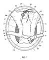
Figure 1 is an underside view of a helmet in accordance with the present invention and showing a retaining strap; -
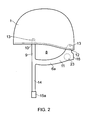
Figure 2 is a side view of the helmet with the strap undone, and -
Figure 3 illustrates only the strap of the helmet offigures 1 and2 . - Referring now to the drawings, the helmet comprises a hard rigid bowl-shaped
outer shell 1 and aninner lining 2 that sits inside the shell. The edge of the shell and the lining defines amouth 3 that is lined by a cushionedheadband 4 which is padded for wearer comfort by incorporating and/or being formed of padding material. Preferably, the headband is both soft and flexible. - In order to secure the helmet to the wearer's head there is a
harness 5 that comprises twostrap halves outer shell 1 and theinner lining 2 and depends therefrom such that when a user wears the helmet, the twostrap halves - The
headband 4 is attached to theshell 1 by amaterial hinge 7 and to portions of thelining 2 by an adhesive (not shown). Thehinge 7 may be formed of any flexible material, including the material forming theheadband 4, or any part thereof. Thehinge 7 is mainly fixed between the lining and the shell, but in some places it is fixed between the lining and part of a strap half. - Each
strap half helmet shell 1 at two spaced locations and is configured to depend downwardly from those locations on one side of the wearer's head in such a way as to form aloop 8 with the edge of the helmet shell, the loop passing around the ear of the wearer. Afront part 9 of the strap half is fixed to a side portion of the helmet at afirst end 10 and extends substantially downwardly from the edge of theshell 1 whereas arear part 11 of thestrap half front part 9, extends rearwardly from thefront part 9 to asecond end 12 where it is fixed adjacent to the rear of the helmet. In each case the first andsecond ends strap half outer shell 1 and thelining 2 and fixed in place by arivet 13, although it is to be understood that other fixings may be used. The position of thesecond ends 12 of the strap halves are disposed such that the rivets and are separated by a distance of around 180mm, although it is to be understood that this may be varied by around +/20mm at least. - At the intersection of the front and
rear parts strap half 6a on one side there is anelongate extension piece 14 to the strap that is designed to pass under the wearer's chin and which terminates in afirst part 15a of areleasable clip fastener 15. The intersection of thestrap parts second part 15b of theclip fastener 15. - Towards the rear of the helmet, adjacent the
second end 12 of eachstrap half tab 16 that extends from therear part 11. The front edge of the tab has threeeyelets 17 by which it may be fastened to thecorresponding tab 16 on the other strap half by means of a lace 18. Thecorresponding tab 16 similarly has three eyelets along its front edge. - When the helmet is worn the
strap halves extension piece 14 is passed under the chin and the twoparts clip 15 fastened together and tightened so as to bring the strap halves together in a secure fit to the wearer's head. - The
strap halves inner web 19, which may be of reinforced woven material, that is covered by asoft leather sleeve 20 for comfort. This is depicted infigure 3 . Achin pad 21 may be provided over theextension piece 14. - At the intersection of the
second part 11 of the strap half with thetab part 16 there is a relatively wide portion of the sleeve defining apocket 22 in which asuction cup 23 is received (seefigure 1 and3 and, in particular, the inset tofigure 3 ). Thesuction cup 23 comprises a disc of elastomeric rubber or plastics material such as polyvinylchloride or the like that is dished so as to have a convex outer surface and a concave inner surface for facing the head of the wearer. The concave side of the cup bears against the side of the wearer's head and when the harness is tensioned the cup is deformed to a flatter profile such that air is expelled out of the cup. The reaction force applied by the cup allows the harness to "grip" the wearer's head slightly so that a good fit is ensured whilst providing additional comfort. In order to enhance comfort further, a circularrenticulated foam pad 23a is inserted in thepocket 22 between the concave inner surface of thesuction cup 23 and the harness. It is to be understood that any type of resiliently deformable pad or element may be used in place of the suction cup. - The second end of the strap half is fixed at a location on the helmet that is spaced further from the rearmost point of the helmet out compared to the location on a conventional helmet so that the second part of the strap half passes more around the side of the wearer's head than the rear. It will be appreciated that in the embodiment shown in the figures this spacing is about 90mm. However, it may be in the region of 80 to 100mm and still achieve the same effect. The combination of this position and the presence of the cup serves to generate a better combination of forces for retaining the helmet on the wearer's head without impairing comfort and ensuring that the helmet is a good fit.
- It will be appreciated that the above embodiment is described for example only and that numerous modifications could be made to the design without departing from the scope of the invention as defined by the claims. For instance, whilst the harness may be in the form of a strap it will be appreciated that it may take any suitable form such as webbing, chord or the like. Moreover, the suction cup could be replaced by any shape or form of resilient material that deforms upon tensioning of the harness against the wearer's head. Furthermore, the strap need not necessarily be configured so as to have two halves but may take any suitable form, for example it may comprise one strap piece that is attached to one side of the helmet shell and which is releasably fastened to the other.
- Each of the strap halves could be fixed at three or more locations.
- The shell is preferably rigid, and may be covered or coated for aesthetic reasons. The shell can be made from any one or more of glass fibre, polyester resin, carbon fibre, kevlar, abs (acrylonitrile butadiene styrene), high impact styrene, high density polyethylene or other suitable thermoplastic or thermoset plastic.
- The lining may be made from any impact absorbing material, including EPS (expanded polystyrene), EPE (expanded polyethylene), EPP (expanded polypropylene) or a foamed polyurethane.
- The headband can be made from any one of leather, suede, faux leather, faux suede, polyester, nylon, cotton or wool. The internal webbing of the strap halves can be made from any one of cotton, nylon, polyester, polypropylene, or a mixture thereof.
Claims (15)
- A helmet for protecting the head of a wearer comprising:a helmet body (1); anda strap (5) for coupling the helmet to the head, the strap (5) being secured to the helmet body (1);the strap (5) comprising a first portion (9) intended to pass under the chin of a wearer and a second portion (11) joined to said first portion (9) and intended to pass around the rear and side of a wearer's head;the first portion (9) having an end (10) that is secured to the helmet body (1) at a first location and the second portion (11) having an end (12) that is secured to the helmet body (1) at a second location spaced from the first location;the second portion (11) of the strap defining a pocket (22) that contains a resiliently deformable element (23).
- A helmet according to claim 1, wherein the resiliently deformable element (23) is a pad.
- A helmet according to claim 2, wherein the resiliently deformable element (23) has a convex side and a concave side.
- A helmet according to claim 3, wherein the resiliently deformable element (23) is arranged in the pocket (22) such that the concave side faces the wearer.
- A helmet according to any one of claim 1, wherein the resiliently deformable element (23) is an elastomeric suction cup.
- A helmet according to claim 1, wherein the second location is spaced from a rearmost portion of helmet body (1).
- A helmet according to claim 1, wherein the strap (5) comprises two portions (6a, 6b), each having a first portion (9) with an end (10) and a second portion (11) with an end (12).
- A helmet according to claim 7, wherein the helmet body comprises an outer shell (1) and an inner lining (2).
- A helmet according to claim 8, wherein the first and second ends (9, 12) of the strap (5) are secured to the body at a point between the outer shell (1) and the inner lining (2).
- A helmet according to claim 7, further comprising a tab (16) extending from the second portion (11) of each strap part (6a, 6b), the tabs (11) being fastenable together.
- A helmet according to claim 1, wherein the strap (5) has an inner web (19) and an outer comfort layer (20), the pocket (22) being defined between the two.
- A helmet according to claim 1, wherein the pocket (22) is adjacent to the end of the second portion (11) that is secured to the body (1) at the second location.
- A helmet according to claim 1, wherein the outer shell (1) defines an inwardly facing surface extending to an edge of the shell (1), and the inner lining (2) defines an outer surface facing the inwardly facing surface of the shell (1), the lining (2) having an inner surface which in use faces the head of a person wearing the helmet.
- A helmet comprising:a helmet body (1); anda strap (5) for coupling the helmet to the head, the strap (5) being secured to thehelmet body (1);the strap (5) comprising a first portion (9) intended to pass under the chin of a wearer and a second portion (11) joined to said first portion (9) and intended to pass around the rear and side of a wearer's head;the first portion (9) having an end (10) that is secured to the helmet body (11) at a first location and the second portion (11) having an end (12) that is secured to the helmet body (1) at a second location spaced from the first location;the second portion being secured to the helmet body (1) at a location that is about 80 to 100mm from a rearmost portion of helmet.
- A helmet according to claim 14, wherein the second portion (11) is secured to the helmet body (1) at a location that is about 90mm from the rearmost portion of the helmet.
Applications Claiming Priority (1)
| Application Number | Priority Date | Filing Date | Title |
|---|---|---|---|
| GB0723347A GB2455112A (en) | 2007-11-28 | 2007-11-28 | A helmet strap arrangement |
Publications (3)
| Publication Number | Publication Date |
|---|---|
| EP2064963A2 true EP2064963A2 (en) | 2009-06-03 |
| EP2064963A3 EP2064963A3 (en) | 2010-05-26 |
| EP2064963B1 EP2064963B1 (en) | 2011-12-21 |
Family
ID=39048050
Family Applications (1)
| Application Number | Title | Priority Date | Filing Date |
|---|---|---|---|
| EP08253665A Not-in-force EP2064963B1 (en) | 2007-11-28 | 2008-11-07 | A Helmet |
Country Status (4)
| Country | Link |
|---|---|
| US (1) | US8561216B2 (en) |
| EP (1) | EP2064963B1 (en) |
| AT (1) | ATE537719T1 (en) |
| GB (1) | GB2455112A (en) |
Families Citing this family (6)
| Publication number | Priority date | Publication date | Assignee | Title |
|---|---|---|---|---|
| GB2455112A (en) * | 2007-11-28 | 2009-06-03 | Charles Owen And Company | A helmet strap arrangement |
| US9095182B1 (en) | 2010-12-23 | 2015-08-04 | Robert S. Rochholz | Anti-chafing chin strap accessory |
| USD666779S1 (en) | 2011-06-15 | 2012-09-04 | A7 Helmet Systems, Llc | Helmet padding |
| US9629410B2 (en) | 2011-08-16 | 2017-04-25 | Trek Bicycle Corporation | Anti-pinch apparel closure |
| US20180199653A1 (en) * | 2017-01-18 | 2018-07-19 | Quentin Kelly Paige, SR. | Lightweight protective headgear |
| IT202100007142A1 (en) * | 2021-03-24 | 2022-09-24 | Kep Italia S R L | STRAP FOR A HELMET |
Family Cites Families (24)
| Publication number | Priority date | Publication date | Assignee | Title |
|---|---|---|---|---|
| FR1083748A (en) * | 1953-07-30 | 1955-01-12 | Impact protection helmet | |
| US2769176A (en) * | 1954-09-24 | 1956-11-06 | Stephen V Grancsay | Nape strap |
| US3381305A (en) * | 1966-01-10 | 1968-05-07 | Frank D. Buzzelli | Swim cap |
| US3790962A (en) * | 1972-01-07 | 1974-02-12 | M Plastino | Head protecting headwear |
| US3852821A (en) * | 1973-06-11 | 1974-12-10 | L Mickel | Impact absorbent pad for helmet shell |
| US4423524A (en) * | 1981-02-26 | 1984-01-03 | A-T-O Inc. | Suspension system for headgear |
| US4724549A (en) * | 1984-12-11 | 1988-02-16 | Airsorb Pty. Ltd. | Protective helmet and locking means |
| US4947488A (en) * | 1990-02-06 | 1990-08-14 | Ashinoff Leslie A | Forehead guard |
| US5115382A (en) * | 1990-09-28 | 1992-05-19 | Smith Robert C | Headlamp apparatus |
| US5377360A (en) * | 1993-06-02 | 1995-01-03 | Fleitman; Jeffrey P. | Decorative, comfortable, ultra-absorbent sweatband |
| US5774901A (en) * | 1996-08-15 | 1998-07-07 | Bell Sports, Inc. | Sport helmet retention apparatus |
| US5930841A (en) * | 1997-03-21 | 1999-08-03 | Soccer Strategies/Llc | Soccer headguard |
| US5946734A (en) * | 1997-04-15 | 1999-09-07 | Vogan; Richard B. | Head protector apparatus |
| US5898950A (en) * | 1997-11-26 | 1999-05-04 | Sport Maska Inc. | Protective helmet |
| US6625820B1 (en) * | 2000-04-24 | 2003-09-30 | Affinity Soccer, Inc | Protective headguard |
| US20050193477A1 (en) * | 2001-03-21 | 2005-09-08 | Martin Penny | Protective headgear |
| US6446271B1 (en) * | 2001-05-31 | 2002-09-10 | Chang-Hsien Ho | Auxiliary buffer envelope device for inner pad of safety helmet |
| US6438761B1 (en) * | 2001-09-13 | 2002-08-27 | Mcgarrity Sean | Protective headband for heading a ball |
| WO2003096832A1 (en) * | 2002-05-14 | 2003-11-27 | Whitewater Research And Safety Institute, Inc. | Protective headgear for whitewater use |
| US6978487B2 (en) * | 2002-08-22 | 2005-12-27 | Abraham Carl J | Apparatus for enhancing absorption and dissipation of impact forces for sweatbands used in connection with helmets |
| US7222374B2 (en) * | 2004-05-26 | 2007-05-29 | Bell Sports, Inc. | Head gear fitting system |
| US20060206994A1 (en) * | 2005-03-15 | 2006-09-21 | Artisent, Inc. | Safety helmet and components thereof |
| US7827617B2 (en) * | 2005-10-21 | 2010-11-09 | Bae Systems Specialty Defense Systems Of Pennsylvania, Inc. | Chin strap assembly for helmet |
| GB2455112A (en) * | 2007-11-28 | 2009-06-03 | Charles Owen And Company | A helmet strap arrangement |
-
2007
- 2007-11-28 GB GB0723347A patent/GB2455112A/en not_active Withdrawn
-
2008
- 2008-10-10 US US12/248,926 patent/US8561216B2/en not_active Expired - Fee Related
- 2008-11-07 AT AT08253665T patent/ATE537719T1/en active
- 2008-11-07 EP EP08253665A patent/EP2064963B1/en not_active Not-in-force
Non-Patent Citations (1)
| Title |
|---|
| None |
Also Published As
| Publication number | Publication date |
|---|---|
| US8561216B2 (en) | 2013-10-22 |
| GB2455112A (en) | 2009-06-03 |
| EP2064963A3 (en) | 2010-05-26 |
| GB0723347D0 (en) | 2008-01-30 |
| ATE537719T1 (en) | 2012-01-15 |
| US20090133183A1 (en) | 2009-05-28 |
| EP2064963B1 (en) | 2011-12-21 |
Similar Documents
| Publication | Publication Date | Title |
|---|---|---|
| US11638457B2 (en) | Protective helmet | |
| US8561216B2 (en) | Helmet | |
| US20170347736A1 (en) | Helmet comprising integrated rotational impact attenuation and fit system | |
| US9681695B2 (en) | Helmet with chin cup | |
| US8959668B1 (en) | Chinstrap with jaw protection | |
| US5685021A (en) | Protective headgear for wrestler | |
| JPS6055601B2 (en) | protective helmet | |
| US20240164467A1 (en) | Impact attenuating helmet with inner and outer liner and securing attachment | |
| US20150313307A1 (en) | Helmet adapted to its usage constraints | |
| US3600713A (en) | Athletic helmet | |
| TW201114380A (en) | Open face helmet | |
| US6418565B1 (en) | Wrestling ear guard | |
| US10939721B2 (en) | Helmet with integrated shoulder pad | |
| US5657492A (en) | Protective head device | |
| CN110811052B (en) | Helmet with front mounting system elastic connector | |
| US20060130219A1 (en) | Helmet | |
| EP3549468B1 (en) | Helmet with floating brow band | |
| JP2022170123A (en) | Helmet | |
| JP3609044B2 (en) | helmet | |
| WO2022091154A1 (en) | Removable internal covering for helmet, helmet including this covering and kit including a plurality of such coverings | |
| CA2822722A1 (en) | Helmet with chin cup |
Legal Events
| Date | Code | Title | Description |
|---|---|---|---|
| PUAI | Public reference made under article 153(3) epc to a published international application that has entered the european phase |
Free format text: ORIGINAL CODE: 0009012 |
|
| AK | Designated contracting states |
Kind code of ref document: A2 Designated state(s): AT BE BG CH CY CZ DE DK EE ES FI FR GB GR HR HU IE IS IT LI LT LU LV MC MT NL NO PL PT RO SE SI SK TR |
|
| AX | Request for extension of the european patent |
Extension state: AL BA MK RS |
|
| PUAL | Search report despatched |
Free format text: ORIGINAL CODE: 0009013 |
|
| AK | Designated contracting states |
Kind code of ref document: A3 Designated state(s): AT BE BG CH CY CZ DE DK EE ES FI FR GB GR HR HU IE IS IT LI LT LU LV MC MT NL NO PL PT RO SE SI SK TR |
|
| AX | Request for extension of the european patent |
Extension state: AL BA MK RS |
|
| 17P | Request for examination filed |
Effective date: 20101126 |
|
| AKX | Designation fees paid |
Designated state(s): AT BE BG CH CY CZ DE DK EE ES FI FR GB GR HR HU IE IS IT LI LT LU LV MC MT NL NO PL PT RO SE SI SK TR |
|
| 17Q | First examination report despatched |
Effective date: 20110127 |
|
| GRAP | Despatch of communication of intention to grant a patent |
Free format text: ORIGINAL CODE: EPIDOSNIGR1 |
|
| RAP1 | Party data changed (applicant data changed or rights of an application transferred) |
Owner name: CHARLES OWEN & COMPANY (BOW) LIMITED |
|
| GRAS | Grant fee paid |
Free format text: ORIGINAL CODE: EPIDOSNIGR3 |
|
| GRAA | (expected) grant |
Free format text: ORIGINAL CODE: 0009210 |
|
| AK | Designated contracting states |
Kind code of ref document: B1 Designated state(s): AT BE BG CH CY CZ DE DK EE ES FI FR GB GR HR HU IE IS IT LI LT LU LV MC MT NL NO PL PT RO SE SI SK TR |
|
| REG | Reference to a national code |
Ref country code: GB Ref legal event code: FG4D |
|
| REG | Reference to a national code |
Ref country code: CH Ref legal event code: EP |
|
| REG | Reference to a national code |
Ref country code: AT Ref legal event code: REF Ref document number: 537719 Country of ref document: AT Kind code of ref document: T Effective date: 20120115 |
|
| REG | Reference to a national code |
Ref country code: IE Ref legal event code: FG4D |
|
| REG | Reference to a national code |
Ref country code: DE Ref legal event code: R096 Ref document number: 602008012143 Country of ref document: DE Effective date: 20120301 |
|
| REG | Reference to a national code |
Ref country code: SE Ref legal event code: TRGR |
|
| REG | Reference to a national code |
Ref country code: NL Ref legal event code: VDEP Effective date: 20111221 |
|
| PG25 | Lapsed in a contracting state [announced via postgrant information from national office to epo] |
Ref country code: NO Free format text: LAPSE BECAUSE OF FAILURE TO SUBMIT A TRANSLATION OF THE DESCRIPTION OR TO PAY THE FEE WITHIN THE PRESCRIBED TIME-LIMIT Effective date: 20120321 Ref country code: LT Free format text: LAPSE BECAUSE OF FAILURE TO SUBMIT A TRANSLATION OF THE DESCRIPTION OR TO PAY THE FEE WITHIN THE PRESCRIBED TIME-LIMIT Effective date: 20111221 |
|
| LTIE | Lt: invalidation of european patent or patent extension |
Effective date: 20111221 |
|
| PG25 | Lapsed in a contracting state [announced via postgrant information from national office to epo] |
Ref country code: HR Free format text: LAPSE BECAUSE OF FAILURE TO SUBMIT A TRANSLATION OF THE DESCRIPTION OR TO PAY THE FEE WITHIN THE PRESCRIBED TIME-LIMIT Effective date: 20111221 Ref country code: GR Free format text: LAPSE BECAUSE OF FAILURE TO SUBMIT A TRANSLATION OF THE DESCRIPTION OR TO PAY THE FEE WITHIN THE PRESCRIBED TIME-LIMIT Effective date: 20120322 Ref country code: LV Free format text: LAPSE BECAUSE OF FAILURE TO SUBMIT A TRANSLATION OF THE DESCRIPTION OR TO PAY THE FEE WITHIN THE PRESCRIBED TIME-LIMIT Effective date: 20111221 Ref country code: NL Free format text: LAPSE BECAUSE OF FAILURE TO SUBMIT A TRANSLATION OF THE DESCRIPTION OR TO PAY THE FEE WITHIN THE PRESCRIBED TIME-LIMIT Effective date: 20111221 Ref country code: SI Free format text: LAPSE BECAUSE OF FAILURE TO SUBMIT A TRANSLATION OF THE DESCRIPTION OR TO PAY THE FEE WITHIN THE PRESCRIBED TIME-LIMIT Effective date: 20111221 |
|
| PG25 | Lapsed in a contracting state [announced via postgrant information from national office to epo] |
Ref country code: CY Free format text: LAPSE BECAUSE OF FAILURE TO SUBMIT A TRANSLATION OF THE DESCRIPTION OR TO PAY THE FEE WITHIN THE PRESCRIBED TIME-LIMIT Effective date: 20111221 Ref country code: BE Free format text: LAPSE BECAUSE OF FAILURE TO SUBMIT A TRANSLATION OF THE DESCRIPTION OR TO PAY THE FEE WITHIN THE PRESCRIBED TIME-LIMIT Effective date: 20111221 |
|
| PG25 | Lapsed in a contracting state [announced via postgrant information from national office to epo] |
Ref country code: CZ Free format text: LAPSE BECAUSE OF FAILURE TO SUBMIT A TRANSLATION OF THE DESCRIPTION OR TO PAY THE FEE WITHIN THE PRESCRIBED TIME-LIMIT Effective date: 20111221 Ref country code: IS Free format text: LAPSE BECAUSE OF FAILURE TO SUBMIT A TRANSLATION OF THE DESCRIPTION OR TO PAY THE FEE WITHIN THE PRESCRIBED TIME-LIMIT Effective date: 20120421 Ref country code: SK Free format text: LAPSE BECAUSE OF FAILURE TO SUBMIT A TRANSLATION OF THE DESCRIPTION OR TO PAY THE FEE WITHIN THE PRESCRIBED TIME-LIMIT Effective date: 20111221 Ref country code: BG Free format text: LAPSE BECAUSE OF FAILURE TO SUBMIT A TRANSLATION OF THE DESCRIPTION OR TO PAY THE FEE WITHIN THE PRESCRIBED TIME-LIMIT Effective date: 20120321 Ref country code: EE Free format text: LAPSE BECAUSE OF FAILURE TO SUBMIT A TRANSLATION OF THE DESCRIPTION OR TO PAY THE FEE WITHIN THE PRESCRIBED TIME-LIMIT Effective date: 20111221 |
|
| PG25 | Lapsed in a contracting state [announced via postgrant information from national office to epo] |
Ref country code: PT Free format text: LAPSE BECAUSE OF FAILURE TO SUBMIT A TRANSLATION OF THE DESCRIPTION OR TO PAY THE FEE WITHIN THE PRESCRIBED TIME-LIMIT Effective date: 20120423 Ref country code: PL Free format text: LAPSE BECAUSE OF FAILURE TO SUBMIT A TRANSLATION OF THE DESCRIPTION OR TO PAY THE FEE WITHIN THE PRESCRIBED TIME-LIMIT Effective date: 20111221 Ref country code: RO Free format text: LAPSE BECAUSE OF FAILURE TO SUBMIT A TRANSLATION OF THE DESCRIPTION OR TO PAY THE FEE WITHIN THE PRESCRIBED TIME-LIMIT Effective date: 20111221 |
|
| REG | Reference to a national code |
Ref country code: AT Ref legal event code: MK05 Ref document number: 537719 Country of ref document: AT Kind code of ref document: T Effective date: 20111221 |
|
| PLBE | No opposition filed within time limit |
Free format text: ORIGINAL CODE: 0009261 |
|
| STAA | Information on the status of an ep patent application or granted ep patent |
Free format text: STATUS: NO OPPOSITION FILED WITHIN TIME LIMIT |
|
| PG25 | Lapsed in a contracting state [announced via postgrant information from national office to epo] |
Ref country code: DK Free format text: LAPSE BECAUSE OF FAILURE TO SUBMIT A TRANSLATION OF THE DESCRIPTION OR TO PAY THE FEE WITHIN THE PRESCRIBED TIME-LIMIT Effective date: 20111221 |
|
| 26N | No opposition filed |
Effective date: 20120924 |
|
| PG25 | Lapsed in a contracting state [announced via postgrant information from national office to epo] |
Ref country code: IT Free format text: LAPSE BECAUSE OF FAILURE TO SUBMIT A TRANSLATION OF THE DESCRIPTION OR TO PAY THE FEE WITHIN THE PRESCRIBED TIME-LIMIT Effective date: 20111221 |
|
| REG | Reference to a national code |
Ref country code: DE Ref legal event code: R097 Ref document number: 602008012143 Country of ref document: DE Effective date: 20120924 |
|
| PG25 | Lapsed in a contracting state [announced via postgrant information from national office to epo] |
Ref country code: AT Free format text: LAPSE BECAUSE OF FAILURE TO SUBMIT A TRANSLATION OF THE DESCRIPTION OR TO PAY THE FEE WITHIN THE PRESCRIBED TIME-LIMIT Effective date: 20111221 |
|
| PG25 | Lapsed in a contracting state [announced via postgrant information from national office to epo] |
Ref country code: ES Free format text: LAPSE BECAUSE OF FAILURE TO SUBMIT A TRANSLATION OF THE DESCRIPTION OR TO PAY THE FEE WITHIN THE PRESCRIBED TIME-LIMIT Effective date: 20120401 |
|
| PG25 | Lapsed in a contracting state [announced via postgrant information from national office to epo] |
Ref country code: FI Free format text: LAPSE BECAUSE OF FAILURE TO SUBMIT A TRANSLATION OF THE DESCRIPTION OR TO PAY THE FEE WITHIN THE PRESCRIBED TIME-LIMIT Effective date: 20111221 |
|
| REG | Reference to a national code |
Ref country code: CH Ref legal event code: PL |
|
| PG25 | Lapsed in a contracting state [announced via postgrant information from national office to epo] |
Ref country code: LI Free format text: LAPSE BECAUSE OF NON-PAYMENT OF DUE FEES Effective date: 20121130 Ref country code: CH Free format text: LAPSE BECAUSE OF NON-PAYMENT OF DUE FEES Effective date: 20121130 |
|
| REG | Reference to a national code |
Ref country code: IE Ref legal event code: MM4A |
|
| REG | Reference to a national code |
Ref country code: FR Ref legal event code: ST Effective date: 20130731 |
|
| PG25 | Lapsed in a contracting state [announced via postgrant information from national office to epo] |
Ref country code: IE Free format text: LAPSE BECAUSE OF NON-PAYMENT OF DUE FEES Effective date: 20121107 |
|
| PG25 | Lapsed in a contracting state [announced via postgrant information from national office to epo] |
Ref country code: FR Free format text: LAPSE BECAUSE OF NON-PAYMENT OF DUE FEES Effective date: 20121130 Ref country code: MT Free format text: LAPSE BECAUSE OF FAILURE TO SUBMIT A TRANSLATION OF THE DESCRIPTION OR TO PAY THE FEE WITHIN THE PRESCRIBED TIME-LIMIT Effective date: 20111221 |
|
| PG25 | Lapsed in a contracting state [announced via postgrant information from national office to epo] |
Ref country code: MC Free format text: LAPSE BECAUSE OF NON-PAYMENT OF DUE FEES Effective date: 20121130 Ref country code: TR Free format text: LAPSE BECAUSE OF FAILURE TO SUBMIT A TRANSLATION OF THE DESCRIPTION OR TO PAY THE FEE WITHIN THE PRESCRIBED TIME-LIMIT Effective date: 20111221 |
|
| PG25 | Lapsed in a contracting state [announced via postgrant information from national office to epo] |
Ref country code: LU Free format text: LAPSE BECAUSE OF NON-PAYMENT OF DUE FEES Effective date: 20121107 |
|
| PG25 | Lapsed in a contracting state [announced via postgrant information from national office to epo] |
Ref country code: HU Free format text: LAPSE BECAUSE OF FAILURE TO SUBMIT A TRANSLATION OF THE DESCRIPTION OR TO PAY THE FEE WITHIN THE PRESCRIBED TIME-LIMIT Effective date: 20081107 |
|
| REG | Reference to a national code |
Ref country code: GB Ref legal event code: 732E Free format text: REGISTERED BETWEEN 20170119 AND 20170125 |
|
| REG | Reference to a national code |
Ref country code: DE Ref legal event code: R081 Ref document number: 602008012143 Country of ref document: DE Owner name: PEMBROKE BOW LIMITED, MICKLE TRAFFORD, GB Free format text: FORMER OWNER: CHARLES OWEN & COMPANY (BOW) LIMITED, WREXHAM, GB |
|
| REG | Reference to a national code |
Ref country code: GB Ref legal event code: 732E Free format text: REGISTERED BETWEEN 20211125 AND 20211201 |
|
| PGFP | Annual fee paid to national office [announced via postgrant information from national office to epo] |
Ref country code: SE Payment date: 20211118 Year of fee payment: 14 Ref country code: DE Payment date: 20211118 Year of fee payment: 14 Ref country code: GB Payment date: 20211103 Year of fee payment: 14 |
|
| REG | Reference to a national code |
Ref country code: DE Ref legal event code: R119 Ref document number: 602008012143 Country of ref document: DE |
|
| REG | Reference to a national code |
Ref country code: SE Ref legal event code: EUG |
|
| GBPC | Gb: european patent ceased through non-payment of renewal fee |
Effective date: 20221107 |
|
| PG25 | Lapsed in a contracting state [announced via postgrant information from national office to epo] |
Ref country code: SE Free format text: LAPSE BECAUSE OF NON-PAYMENT OF DUE FEES Effective date: 20221108 |
|
| PG25 | Lapsed in a contracting state [announced via postgrant information from national office to epo] |
Ref country code: GB Free format text: LAPSE BECAUSE OF NON-PAYMENT OF DUE FEES Effective date: 20221107 Ref country code: DE Free format text: LAPSE BECAUSE OF NON-PAYMENT OF DUE FEES Effective date: 20230601 |