EP2064765B1 - Electrocatalysts based on mono/plurimetallic carbon nitrides for polymer electrolyte membrane fuel cells fuelled with hydrogen (pemfc) and methanol (dmfc) and for hydrogen electrogenerators - Google Patents
Electrocatalysts based on mono/plurimetallic carbon nitrides for polymer electrolyte membrane fuel cells fuelled with hydrogen (pemfc) and methanol (dmfc) and for hydrogen electrogenerators Download PDFInfo
- Publication number
- EP2064765B1 EP2064765B1 EP07736782.9A EP07736782A EP2064765B1 EP 2064765 B1 EP2064765 B1 EP 2064765B1 EP 07736782 A EP07736782 A EP 07736782A EP 2064765 B1 EP2064765 B1 EP 2064765B1
- Authority
- EP
- European Patent Office
- Prior art keywords
- oxides
- electrocatalyst
- ptcl
- mpm
- pdcl
- Prior art date
- Legal status (The legal status is an assumption and is not a legal conclusion. Google has not performed a legal analysis and makes no representation as to the accuracy of the status listed.)
- Active
Links
Images



Classifications
-
- H—ELECTRICITY
- H01—ELECTRIC ELEMENTS
- H01M—PROCESSES OR MEANS, e.g. BATTERIES, FOR THE DIRECT CONVERSION OF CHEMICAL ENERGY INTO ELECTRICAL ENERGY
- H01M8/00—Fuel cells; Manufacture thereof
- H01M8/10—Fuel cells with solid electrolytes
- H01M8/1004—Fuel cells with solid electrolytes characterised by membrane-electrode assemblies [MEA]
-
- H—ELECTRICITY
- H01—ELECTRIC ELEMENTS
- H01M—PROCESSES OR MEANS, e.g. BATTERIES, FOR THE DIRECT CONVERSION OF CHEMICAL ENERGY INTO ELECTRICAL ENERGY
- H01M4/00—Electrodes
- H01M4/86—Inert electrodes with catalytic activity, e.g. for fuel cells
- H01M4/90—Selection of catalytic material
- H01M4/9008—Organic or organo-metallic compounds
-
- H—ELECTRICITY
- H01—ELECTRIC ELEMENTS
- H01M—PROCESSES OR MEANS, e.g. BATTERIES, FOR THE DIRECT CONVERSION OF CHEMICAL ENERGY INTO ELECTRICAL ENERGY
- H01M4/00—Electrodes
- H01M4/86—Inert electrodes with catalytic activity, e.g. for fuel cells
- H01M4/90—Selection of catalytic material
- H01M4/9075—Catalytic material supported on carriers, e.g. powder carriers
- H01M4/9083—Catalytic material supported on carriers, e.g. powder carriers on carbon or graphite
-
- H—ELECTRICITY
- H01—ELECTRIC ELEMENTS
- H01M—PROCESSES OR MEANS, e.g. BATTERIES, FOR THE DIRECT CONVERSION OF CHEMICAL ENERGY INTO ELECTRICAL ENERGY
- H01M4/00—Electrodes
- H01M4/86—Inert electrodes with catalytic activity, e.g. for fuel cells
- H01M4/90—Selection of catalytic material
- H01M4/92—Metals of platinum group
- H01M4/923—Compounds thereof with non-metallic elements
-
- H—ELECTRICITY
- H01—ELECTRIC ELEMENTS
- H01M—PROCESSES OR MEANS, e.g. BATTERIES, FOR THE DIRECT CONVERSION OF CHEMICAL ENERGY INTO ELECTRICAL ENERGY
- H01M4/00—Electrodes
- H01M4/86—Inert electrodes with catalytic activity, e.g. for fuel cells
- H01M4/90—Selection of catalytic material
- H01M4/92—Metals of platinum group
- H01M4/925—Metals of platinum group supported on carriers, e.g. powder carriers
- H01M4/926—Metals of platinum group supported on carriers, e.g. powder carriers on carbon or graphite
-
- H—ELECTRICITY
- H01—ELECTRIC ELEMENTS
- H01M—PROCESSES OR MEANS, e.g. BATTERIES, FOR THE DIRECT CONVERSION OF CHEMICAL ENERGY INTO ELECTRICAL ENERGY
- H01M8/00—Fuel cells; Manufacture thereof
- H01M8/10—Fuel cells with solid electrolytes
- H01M8/1009—Fuel cells with solid electrolytes with one of the reactants being liquid, solid or liquid-charged
- H01M8/1011—Direct alcohol fuel cells [DAFC], e.g. direct methanol fuel cells [DMFC]
-
- Y—GENERAL TAGGING OF NEW TECHNOLOGICAL DEVELOPMENTS; GENERAL TAGGING OF CROSS-SECTIONAL TECHNOLOGIES SPANNING OVER SEVERAL SECTIONS OF THE IPC; TECHNICAL SUBJECTS COVERED BY FORMER USPC CROSS-REFERENCE ART COLLECTIONS [XRACs] AND DIGESTS
- Y02—TECHNOLOGIES OR APPLICATIONS FOR MITIGATION OR ADAPTATION AGAINST CLIMATE CHANGE
- Y02E—REDUCTION OF GREENHOUSE GAS [GHG] EMISSIONS, RELATED TO ENERGY GENERATION, TRANSMISSION OR DISTRIBUTION
- Y02E60/00—Enabling technologies; Technologies with a potential or indirect contribution to GHG emissions mitigation
- Y02E60/30—Hydrogen technology
- Y02E60/50—Fuel cells
-
- Y—GENERAL TAGGING OF NEW TECHNOLOGICAL DEVELOPMENTS; GENERAL TAGGING OF CROSS-SECTIONAL TECHNOLOGIES SPANNING OVER SEVERAL SECTIONS OF THE IPC; TECHNICAL SUBJECTS COVERED BY FORMER USPC CROSS-REFERENCE ART COLLECTIONS [XRACs] AND DIGESTS
- Y02—TECHNOLOGIES OR APPLICATIONS FOR MITIGATION OR ADAPTATION AGAINST CLIMATE CHANGE
- Y02P—CLIMATE CHANGE MITIGATION TECHNOLOGIES IN THE PRODUCTION OR PROCESSING OF GOODS
- Y02P70/00—Climate change mitigation technologies in the production process for final industrial or consumer products
- Y02P70/50—Manufacturing or production processes characterised by the final manufactured product
Definitions
- the invention concerns the anodic and cathodic electrocatalysts to be used in fuel cells operating at low temperatures and in H 2 electrolyzers together with the methods used to prepare the materials constituting those electrocatalysts.
- the result is an extremely thin black powder characterized by a large surface area and featuring graphite grains covered by metallic platinum.
- Cathodic electrocatalysts show platinum concentrations equal to 10-20 weight%, while anodic electrocatalysts may also have ruthenium, needed to limit the poisoning effects on the active sites caused by carbon monoxide and other poisoning agents such as halides, ammines, amides produced either by parasitic reactions such as fuel oxidation or present in the reagents in trace amounts.
- One of the main limits towards the large-scale use of this type of materials is their high cost; besides, it should be pointed out that not every metal may be deposited on graphite-based supports by electrochemical means.
- the alloying of a second non-noble metal with platinum may result in an improvement of the electrocatalytic activity of the system.
- the second metal might also act as a protection for the active sites towards contaminants such as carbon monoxide or halides. These contaminants reduce the activity of the active sites of the noble metal constituting the electrocatalyst. This way it becomes possible to obtain materials showing a higher tolerance towards environmental contaminations, having a longer operating lifetime and a lower cost.
- Mono-plurimetallic clusters supported on carbon nitrides or MPM-CN and MPM-CN/oxides electrocatalysts which are the object of this invention can be prepared according to a procedure consisting of three steps, which are outlined below.
- STEP 1 Preparation of a precursor through chemical reactions based on the following transitions: a) sol-gel; b) gel-plastic; c) coagulation and/or flocculation and/or precipitation.
- STEP 2 Pyrolyis process carried out under an inert atmosphere of the precursor obtained in STEP 1.
- STEP 2 yields the MPM-CN or the MPM-CN/oxides electrocatalyst.
- STEP 3 Procedures to perform the chemical and/or electrochemical activation of the MPM-CN or the MPM-CN/oxides electrocatalyst obtained in STEP 2.
- Precursors are obtained as described below in a detailed way through: a) complexation reactions of "soft" transition metals with cyanometallate complexes acting as ligands to produce clusters; b) 3-D networking of the obtained clusters with suitable organic molecules and macromolecules.
- the latter are also the main source of the carbon atoms necessary to provide a good electric conductivity to the MPM-CN or the MPM-CN/oxides electrocatalyst.
- the selected organic substance must be water-soluble, must not contain sulphur atoms and must be very rich of oxygen atoms. Typical examples include polyethylene glycol, polyvinyl alcohol, glycerol, sucrose, glucose, fructose and in general all the water-soluble macromolecules such as carbohydrates.
- solution A consists of a "soft" transition metal complex coordinated by good leaving groups and an aliquot of organic binder dissolved in water.
- Typical examples of "soft" transition metal complexes used in the preparation of the solution A are: HAuCl 4 , H 2 IrCl 6 , H 2 PtCl 6 , Li 2 PdCl 4 , (NH 4 ) 2 IrCl 6 , (NH 4 ) 2 OsCl 6 , (NH 4 )PdCl 4 , (NH 4 ) 2 PdCl 6 , (NH 4 ) 2 PtCl 4 , (NH 4 ) 3 RhCl 6 , (NH 4 ) 2 RuCl 6 , KAuCl 4 , KPt(NH 3 )Cl 3 , K 2 PdCl 4 , K 2 PtCl 6 , K 2 PtCl
- Solution B is obtained by dissolving in water a suitable amount of a metallic cyanometallate complex capable to act as a ligand for "soft" metals, together with an aliquot of the same organic compound used in the preparation of the solution B.
- a metallic cyanometallate complex capable to act as a ligand for "soft" metals
- Typical examples of cyanometalates which can be used are: KAg(CN) 2 , KAu(CN) 2 , K 2 Ni(CN) 4 K 2 Pd(CN) 4 , K 2 Pt(CN) 4 , K 3 Co(CN) 6 , K 3 Cr(CN) 6 K 3 Fe(CN) 6 , K 3 Mn(CN) 6 , K 2 Pt(CN) 6 , K 4 Ru(CN) 6 .
- Solutions A and B must be mixed together and stirred until they are completely transparent.
- Precursors for MPM-CN/oxides electrocatalysts are prepared adding the desired amount of ceramic materials based on oxides with nanometric morphologies to either solution A or B or both.
- ceramic materials based on oxides with nanometric morphologies include: Ag 2 O, Al 2 O 3 , Arsenic oxides, Au 2 O 3 , Bi 2 O 3 , CeO 2 , Cobalt oxides, Chromium oxides, Copper oxides, EuO 2 , Iron oxides, Ga 2 O 3 , HfO 2 , Ir 2 O 3 , La 2 O 3 , MnO 2 , Molybdenum oxides, Niobium oxides, Nd 2 O 3 , NiO, Osmium oxides, Lead oxides, PdO, PrO 2 , Platinum oxides, Rhenium oxides, Rh 2 O 3 , Ruthenium oxides, Antimony oxides, Sc 2 O 3 , Selenium oxides, SiO 2 , SmO, SnO 2
- the precursor obtained in STEP 1 undergoes a pyrolysis process as described below. At first the precursor is kept under dynamic vacuum at 10 -3 bar for 16-24 hours at 150-200°C, then the product is brought to a higher temperature (300-1200°C) for no longer than two hours. Lastly, a further pyrolysis process under a dynamic vacuum (10 -3 bar) is performed at high temperature (400-1200°C), lasting between one and six hours.
- the MPM-CN or MPM-CN/oxides electrocatalyst obtained after STEP 2 is finely ground, at first in a mortar and then in a ball mill and subsequently washed repeatedly with water so as to remove halides and other soluble reaction products.
- the washed MPM-CN or MPM-CN/oxides electrocatalyst is activated through three washings in hydrogen peroxide, 10% vol., and is eventually dried and further ground with a ball mill.
- the reaction between the chloride of the transition metal and the cyanometallate when the organic binder is present results in a compact and homogeneous precursor where the desired quantity of metallic centres is uniformly distributed (STEP 1).
- the pyrolysis process carried out under vacuum removes the oxygen and hydrogen atoms of the organic binder from the material; furthermore, it provides the energy necessary to activate the nucleation and growth of the carbon nitride-based clusters of the MPM-CN or MPM-CN/oxides electrocatalyst (STEP 2).
- the clusters are of nanometric size and have the programmed chemical composition.
- the ceramic materials based on oxides with nanometric morphologies if they are present, provide a matrix featuring an extremely large surface area where the catalytic material based on mono-plurimetallic carbon nitrides can be supported.
- the carbon nitride deriving from the decomposition of the organic binder guarantees to the MPM-CN or MPM-CN/oxides electrocatalyst the electrical conductivity necessary for its operation (STEP 2).
- the main aim of the prolonged washing with bidistilled water is the removal of possible halide-based soluble derivatives: should they bind permanently on the active sites, they would compromise the catalytic activity of the MPM-CN or MPM-CN/oxides electrocatalyst (STEP 3).
- the treatment with hydrogen peroxide is performed so as to "clean" the external surface of the MPM-CN or MPM-CN/oxides electrocatalyst from impurities which could both poison the active catalytic sites and make the active area of the material smaller (STEP 3).
- Solution A was added dropwise into Solution B; the product was stirred for 15 minutes at room temperature and allowed to rest for three days. At the end of this period of time, on the bottom of the vessel a very thin light grey powder was found deposited under a clear, very light yellow solution.
- the sample was transferred into a quartz tube where the drying process was protracted for three days keeping the warming bath at 60°C.
- the final product was a viscous, light blue suspension, which is the precursor of the MPM-CN electrocatalyst.
- the quartz tube containing the precursor obtained at the end of STEP 1 was connected to a vacuum line and brought to 10 -3 bar.
- the precursor placed under vacuum underwent a first pyrolysis process at 180°C for 24 hours; in this phase it appeared opaque and was emerald green.
- the resulting solid was then pyrolysed at 300°C for two hours under dynamic vacuum and was eventually allowed to rest.
- the obtained solid product looked like a blackish, very rough powder. After finely grinding it into a mortar, the product was re-introduced into a quartz tube, where it underwent a further pyrolysis process at 600°C under dynamic vacuum for two hours.
- the MPM-CN electrocatalyst obtained at the end of STEP 2 was removed from the tube, finely ground in a mortar and eventually washed four times with milli-Q water to remove the soluble byproducts and the chloride ions deriving from the chemical reaction.
- the MPM-CN electrocatalyst was dried under an IR lamp. At the end of each washing step the mother waters were separated from the MPM-CN electrocatalyst by centrifugation at 3000 rpm for 15 minutes.
- the resulting MPM-CN electrocatalyst powders were then transferred to a glass beaker and treated with about 40 mL of hydrogen peroxide, 10% vol., as follows. About 5 mL of hydrogen peroxide were used to cover the MPM-CN electrocatalyst, over which a significant evolution of bubbles was observed. The thinnest powders became suspended, and when the bubble evolution stopped they were removed using a Pasteur pipette and transferred into a glass Petri capsule placed under an IR lamp to remove the remaining water.
- the precursor obtained at the end of STEP 1 underwent the following pyrolysis process: 180°C for 24 hours, followed by 300°C for two hours and by 550°C for two hours.
- Solution A was added dropwise into Solution B, stirred for 15 minutes at room temperature and allowed to rest for three days. During this time interval the resulting solution remained clear but it changed its colour from red to light yellow.
- the whole sample was transferred into a quartz tube connected to a rotovapor, and dried for six hours at 60°C. At the end a light yellow transparent solid sample was obtained.
- the quartz tube containing the precursor obtained at the end of STEP 1 was later connected to a vacuum line at 10 -3 bar.
- the sample underwent a first pyrolysis process at 180°C for 24 hours and later pyrolysed at 400°C for two hours under dynamic vacuum.
- the resulting MPM-CN electrocatalyst looked like a very rough blackish powder, it was finely ground into a mortar and was labelled PtCo400.
- the PtCo500 and PtCo700 MPM-CN electrocatalysts were prepared by pyrolysing aliquots of PtCo400 at 500°C and 700°C for two hours, respectively.
- This example describes the synthesis procedure of a MPM-CN electrocatalyst for the cathodic reduction of oxygen based on platinum and iron.
- sucrose 4.46 g were dissolved into 9 mL of milli-Q water. The solution was divided into two aliquots, the former consisting of 4 mL and the latter of 5 mL. 1 g of H 2 PtCl 6 was dissolved into the former aliquot, yielding a yellowish solution (Solution A). 1260 mg of K 3 Fe(CN) 6 were dissolved into the latter aliquot, yielding a yellow solution (Solution B). Solution A was added dropwise into the second, and allowed to rest for a few minutes. Almost instantly, a greenish gel was obtained. The gel was then transferred into a quartz tube and connected to a vacuum line as described in Example 1.
- the precursor obtained at the end of STEP 1 underwent the following pyrolysis process, always maintaining the dynamic vacuum: a) 16 hours at 200°C; b) 1 hour at 900°C; c) 4 hours at 700°C.
- the MPM-CN electrocatalyst obtained at the end of STEP 2 was recovered from the quartz tube and subsequently treated, activated and tested as described in Example 1.
- a weighed aliquot of the electrocatalyst was brought into suspension in a measured amount of milli-Q water by sonication into an ultrasonic bath for about one hour.
- the glassy carbon tip of a rotating electrode was mirror-polished with alumina powder, and a known aliquot of the suspension was transferred on top of it with a micropipette aiming at a platinum loading of about 4.7 ⁇ g Pt/cm 2 .
- the water of the suspension was later removed by placing the tip under an IR lamp.
- the resulting electrocatalyst layer was later bound to the rotating electrode tip by covering it with a known amount of a solution obtained diluting 100 times with milli-Q water a commercial 5 wt% NafionTM solution.
- the aim is to cover the electrocatalyst with a Nafion film about 150 nm thick, so as to obtain a good adhesion of the electrocatalyst without introducing diffusion barriers hindering the feeding of oxygen to the electrocatalyst during the measurement.
- Water was removed from the solution by drying under an IR lamp.
- the electrode was later placed into an electrolytic solution consisting of perchloric acid with a concentration of 0.1 M, kept at 60°C.
- the electrode tip was always rotated at a fixed speed, 1600 rpm.
- the cyclic voltammetric measurements were collected in a potential window between 0.05 and 1.15 V vs. NHE, at a sweep rate of 100 mV/sec.
- the electrocatalyst activation was performed cycling the electrode for 15 hours at 20 mV/sec in nitrogen atmosphere.
- the electrocatalyst was further cleaned by continuing the cycling for six hours in a pure oxygen atmosphere, kept at the pressure of 1 bar.
- Tab 2 also shows the potential this maximum is located at. Tab.2.
- Electrochemical features of selected MPM-CN and MPM-CN/oxides electocatalysts for PEFC and DMFC fuel cells.
- the MPM-CN electrocatalyst prepared according to the procedure outlined in Example 1 shows performances similar to those of the best tested commercial electrocatalyst, in this case the EC-10 produced by ElectroChem Inc.
- the MPM-CN electrocatalyst prepared according to the procedure described in Example 9 it can be observed that the mass activity at 0.6 V is barely below that of the second best commercial electrocatalyst, i.e. EC-20/10, while its maximum mass power is better than that shown by the PtNi600 MPM-CN electrocatalyst and barely lower than that of the best tested commercial electrocatalyst.
- the difference between the two voltammogramms as a first approximation corresponds to the characteristic voltammogramm which can be associated to active platinum sites, active in the oxidation reaction of hydrogen and methanol.
- the characteristic voltammogramm which can be associated to active platinum sites, active in the oxidation reaction of hydrogen and methanol.
- PtNi600 and PtFe900 MPM-CN electrocatalysts were used in the preparation of membrane-electrode assemblies (MEAs) and tested as cathode electrocatalysts in a single fuel cell.
- the amount of electrocatalyst used to prepare the MEAs was chosen so as to obtain a Pt loading equal to about 0.4 mg Pt/cm 2 of MEA.
- a commercial MEA produced by ElectroChem. Inc. having a Pt loading at the cathode equal to 1 mg Pt/cm 2 of MEA was also tested in the same conditions as reference. The resulting polarization curves are shown on Fig. 5 .
Landscapes
- Chemical & Material Sciences (AREA)
- Engineering & Computer Science (AREA)
- Chemical Kinetics & Catalysis (AREA)
- Electrochemistry (AREA)
- General Chemical & Material Sciences (AREA)
- Materials Engineering (AREA)
- Life Sciences & Earth Sciences (AREA)
- Manufacturing & Machinery (AREA)
- Sustainable Development (AREA)
- Sustainable Energy (AREA)
- Catalysts (AREA)
- Inert Electrodes (AREA)
- Fuel Cell (AREA)
Description
- The invention concerns the anodic and cathodic electrocatalysts to be used in fuel cells operating at low temperatures and in H2 electrolyzers together with the methods used to prepare the materials constituting those electrocatalysts.
- To allow a fuel cell operating at low temperature to produce an adequate amount of current at acceptable potentials it is necessary to achieve a quick and efficient catalytic conversion of the reagents into products. At the anode, the fuel (hydrogen, methanol, ethanol, etc...) is oxidised producing H+ ions and other products; at the cathode, the oxidant (air or oxygen) is reduced developing O2- ions. Nowadays, the best electrocatalysts used in fuel cells operating at low temperatures are based upon platinum, either pure or supported on graphite. Electrodic materials are generally produced through an electrochemical reduction of precursors containing platinum and ruthenium on graphite nanopowders (carbon black). The result is an extremely thin black powder characterized by a large surface area and featuring graphite grains covered by metallic platinum. Cathodic electrocatalysts show platinum concentrations equal to 10-20 weight%, while anodic electrocatalysts may also have ruthenium, needed to limit the poisoning effects on the active sites caused by carbon monoxide and other poisoning agents such as halides, ammines, amides produced either by parasitic reactions such as fuel oxidation or present in the reagents in trace amounts. One of the main limits towards the large-scale use of this type of materials is their high cost; besides, it should be pointed out that not every metal may be deposited on graphite-based supports by electrochemical means.
- It is reported in the scientific literature that the alloying of a second non-noble metal with platinum may result in an improvement of the electrocatalytic activity of the system. The second metal might also act as a protection for the active sites towards contaminants such as carbon monoxide or halides. These contaminants reduce the activity of the active sites of the noble metal constituting the electrocatalyst. This way it becomes possible to obtain materials showing a higher tolerance towards environmental contaminations, having a longer operating lifetime and a lower cost.
- An example of scientific literature on the above matter is Jose L. Fernandez et al.: "Thermodynamic guidelines for the design of bimetallic catalysts for oxygen electroreduction and rapid screening vy Scanning Electrochemical Microscopy. M-Co (M: Pd, Ag, Au)", Journal of the American Chemical Society, American Chemical Society, (2005), vol. 127 (1), pages 357-365. A variety of fuel cell catalysts based on transition metal nitrides on carbon supports are described in
WO 2007 /098432 A2 . - The invention is disclosed in the independent claims 1 and 11-13. The dependent claims describe preferred embodiments. Mono-plurimetallic clusters supported on carbon nitrides or MPM-CN and MPM-CN/oxides electrocatalysts which are the object of this invention can be prepared according to a procedure consisting of three steps, which are outlined below.
- STEP 1. Preparation of a precursor through chemical reactions based on the following transitions: a) sol-gel; b) gel-plastic; c) coagulation and/or flocculation and/or precipitation.
- STEP 2. Pyrolyis process carried out under an inert atmosphere of the precursor obtained in STEP 1. STEP 2 yields the MPM-CN or the MPM-CN/oxides electrocatalyst.
- STEP 3. Procedures to perform the chemical and/or electrochemical activation of the MPM-CN or the MPM-CN/oxides electrocatalyst obtained in STEP 2.
- Precursors are obtained as described below in a detailed way through: a) complexation reactions of "soft" transition metals with cyanometallate complexes acting as ligands to produce clusters; b) 3-D networking of the obtained clusters with suitable organic molecules and macromolecules. The latter are also the main source of the carbon atoms necessary to provide a good electric conductivity to the MPM-CN or the MPM-CN/oxides electrocatalyst. The selected organic substance must be water-soluble, must not contain sulphur atoms and must be very rich of oxygen atoms. Typical examples include polyethylene glycol, polyvinyl alcohol, glycerol, sucrose, glucose, fructose and in general all the water-soluble macromolecules such as carbohydrates.
- Once the most suitable organic compound for the desired synthesis has been chosen, two different solutions are prepared, A and B. The first, solution A, consists of a "soft" transition metal complex coordinated by good leaving groups and an aliquot of organic binder dissolved in water. Typical examples of "soft" transition metal complexes used in the preparation of the solution A are: HAuCl4, H2IrCl6, H2PtCl6, Li2PdCl4, (NH4)2IrCl6, (NH4)2OsCl6, (NH4)PdCl4, (NH4)2PdCl6, (NH4)2PtCl4, (NH4)2PtCl6, (NH4)3RhCl6, (NH4)2RuCl6, KAuCl4, KPt(NH3)Cl3, K2PdCl4, K2PtCl4, K2PdCl6, K2PtCl6, K2ReCl6, K2RhCl6 K2H2IrCl6, K2H2OsCl6, K3IrCl6, K3H3RuCl6, Na2IrCl6, Na2OsCl6, Na2PdCl4, Na2PtCl6, Na3RhCl6, CrCl3, IrCl3, FeCl3, NiCl2, OsCl3, PdCl2, PtCl2, PtCl4, RhCl3, RuCl3, ReCl5, SnCl4, VCl3, VCl4, WCl4, WCl6, ZrCl4.
- Solution B is obtained by dissolving in water a suitable amount of a metallic cyanometallate complex capable to act as a ligand for "soft" metals, together with an aliquot of the same organic compound used in the preparation of the solution B. Typical examples of cyanometalates which can be used are: KAg(CN)2, KAu(CN)2, K2Ni(CN)4 K2Pd(CN)4, K2Pt(CN)4, K3Co(CN)6, K3Cr(CN)6 K3Fe(CN)6, K3Mn(CN)6, K2Pt(CN)6, K4Ru(CN)6.
- Solutions A and B must be mixed together and stirred until they are completely transparent.
- Precursors for MPM-CN/oxides electrocatalysts are prepared adding the desired amount of ceramic materials based on oxides with nanometric morphologies to either solution A or B or both. Examples of ceramic materials based on oxides with nanometric morphologies include: Ag2O, Al2O3, Arsenic oxides, Au2O3, Bi2O3, CeO2, Cobalt oxides, Chromium oxides, Copper oxides, EuO2, Iron oxides, Ga2O3, HfO2, Ir2O3, La2O3, MnO2, Molybdenum oxides, Niobium oxides, Nd2O3, NiO, Osmium oxides, Lead oxides, PdO, PrO2, Platinum oxides, Rhenium oxides, Rh2O3, Ruthenium oxides, Antimony oxides, Sc2O3, Selenium oxides, SiO2, SmO, SnO2, Tantalum oxides, TbO2, Tellurium oxides, TiO2, Vanadium oxides, Tungsten oxides, ZnO, ZrO2.
- Once the solution is well-mixed the resulting product must be let rest at room temperature. The chemical reaction is considered complete when one of the above-mentioned transitions (sol-gel and/or gel/plastic; coagulation and/or flocculation and/or precipitation) is observed. It may be necessary to wait for a few days for these reactions to occur.
- Should the product have the features of a suspension, the excess solvent must be removed. This result can be achieved with two different procedures: a) filtration; or b) by drying the reaction mixture. This latter treatment is performed in a rotovapor at 60°C until a compact and homogeneous solid remains. The drying process may last a few days.
- The precursor obtained in STEP 1 undergoes a pyrolysis process as described below. At first the precursor is kept under dynamic vacuum at 10-3 bar for 16-24 hours at 150-200°C, then the product is brought to a higher temperature (300-1200°C) for no longer than two hours. Lastly, a further pyrolysis process under a dynamic vacuum (10-3 bar) is performed at high temperature (400-1200°C), lasting between one and six hours.
- The MPM-CN or MPM-CN/oxides electrocatalyst obtained after STEP 2 is finely ground, at first in a mortar and then in a ball mill and subsequently washed repeatedly with water so as to remove halides and other soluble reaction products.
- The washed MPM-CN or MPM-CN/oxides electrocatalyst is activated through three washings in hydrogen peroxide, 10% vol., and is eventually dried and further ground with a ball mill.
- The reaction between the chloride of the transition metal and the cyanometallate when the organic binder is present results in a compact and homogeneous precursor where the desired quantity of metallic centres is uniformly distributed (STEP 1). The pyrolysis process carried out under vacuum removes the oxygen and hydrogen atoms of the organic binder from the material; furthermore, it provides the energy necessary to activate the nucleation and growth of the carbon nitride-based clusters of the MPM-CN or MPM-CN/oxides electrocatalyst (STEP 2). The clusters are of nanometric size and have the programmed chemical composition. The ceramic materials based on oxides with nanometric morphologies, if they are present, provide a matrix featuring an extremely large surface area where the catalytic material based on mono-plurimetallic carbon nitrides can be supported. The carbon nitride deriving from the decomposition of the organic binder guarantees to the MPM-CN or MPM-CN/oxides electrocatalyst the electrical conductivity necessary for its operation (STEP 2). The main aim of the prolonged washing with bidistilled water is the removal of possible halide-based soluble derivatives: should they bind permanently on the active sites, they would compromise the catalytic activity of the MPM-CN or MPM-CN/oxides electrocatalyst (STEP 3). The treatment with hydrogen peroxide is performed so as to "clean" the external surface of the MPM-CN or MPM-CN/oxides electrocatalyst from impurities which could both poison the active catalytic sites and make the active area of the material smaller (STEP 3).
- The main features of the invention are highlighted in the following descriptions which should be considered, together with the attached graphs, specific information concerning particular examples reported only for illustrative and not for limitative purposes.
-
-
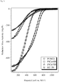
Fig. 1 . CV-TF-RDE profiles of the reduction mass activity of the electrocatalysts indicated in the graph determined by Cyclic Voltammetry (CV) using the TF-RDE method (Thin Film Rotating Disk Electrode). Measurements relative to the commercial electrocatalysts used as references are also reported. CV-TF-RDE measurements are collected at 100 mV/s, 1 bar of pure oxygen and at 60°C using as support electrolyte a 0.1 M solution of HClO4. -
Fig. 2 . CV-TF-RDE profiles of the reduction mass activity of MPM-CN electrocatalysts including platinum and nickel carbon nitrides obtained applying different pyrolysis processes. The conditions of the experimental measurements are the same as those reported inFig. 1 . -
Fig. 3 . CV-TF-RDE profiles of the reduction mass activity of MPM-CN electrocatalysts including platinum and cobalt carbon nitrides obtained applying different pyrolysis processes and of the MPM-CN/oxide electrocatalyst including platinum-nickel carbon nitrides supported on nanometric CeO2. The conditions of the experimental measurements are the same as those reported inFig. 1 . -
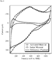
Fig. 4 . Evolution of the cyclic voltammogramms of the PtNi600 MPM-CN electrocatalyst determined with measurements with the CV-TF-RDE method in pure nitrogen atmosphere before (initial material) and after the activation with O2 (activated material). The difference curve shows the typical CV profile of pure platinum. This curve allows the determination of the electrochemically-active area of the electrocatalysts proposed in this invention. -
Fig. 5 . Polarization curves of the MEAs prepared with the PtNi600 and the PtFe900 materials, together with the commercial reference. Experimental conditions: T=87/80/87°C; H2 dew point = 87°C; H2 flux 800 seem; O2 dew point = 85°C; O2 flux 2000 seem; reagents pressure 65 psig. - This example reports the detailed description of the synthesis of a MPM-CN electrocatalyst for the cathodic reduction of oxygen based on platinum and nickel.
- 4.46 g of sucrose were dissolved in 9 mL of milli-Q water; the resulting solution was divided into two aliquots, the former consisting of 4 mL, the latter of 5 mL. 832 mg of K2PtCl4 were dissolved into the former, yielding a deep red clear solution having a 0.5 M concentration in PtCl4 2- complexes (Solution A). 1288 mg of K2Ni(CN)4 with a hydration degree of 30% were dissolved into the latter solution of water and organic binder, yielding a clear light yellow solution having a 0.75 M concentration in Ni(CN)4 2- complexes (Solution B). Solution A was added dropwise into Solution B; the product was stirred for 15 minutes at room temperature and allowed to rest for three days. At the end of this period of time, on the bottom of the vessel a very thin light grey powder was found deposited under a clear, very light yellow solution. The sample was transferred into a quartz tube where the drying process was protracted for three days keeping the warming bath at 60°C. The final product was a viscous, light blue suspension, which is the precursor of the MPM-CN electrocatalyst.
- The quartz tube containing the precursor obtained at the end of STEP 1 was connected to a vacuum line and brought to 10-3 bar. The precursor placed under vacuum underwent a first pyrolysis process at 180°C for 24 hours; in this phase it appeared opaque and was emerald green. The resulting solid was then pyrolysed at 300°C for two hours under dynamic vacuum and was eventually allowed to rest. The obtained solid product looked like a blackish, very rough powder. After finely grinding it into a mortar, the product was re-introduced into a quartz tube, where it underwent a further pyrolysis process at 600°C under dynamic vacuum for two hours.
- The MPM-CN electrocatalyst obtained at the end of STEP 2 was removed from the tube, finely ground in a mortar and eventually washed four times with milli-Q water to remove the soluble byproducts and the chloride ions deriving from the chemical reaction. The MPM-CN electrocatalyst was dried under an IR lamp. At the end of each washing step the mother waters were separated from the MPM-CN electrocatalyst by centrifugation at 3000 rpm for 15 minutes.
- The resulting MPM-CN electrocatalyst powders were then transferred to a glass beaker and treated with about 40 mL of hydrogen peroxide, 10% vol., as follows. About 5 mL of hydrogen peroxide were used to cover the MPM-CN electrocatalyst, over which a significant evolution of bubbles was observed. The thinnest powders became suspended, and when the bubble evolution stopped they were removed using a Pasteur pipette and transferred into a glass Petri capsule placed under an IR lamp to remove the remaining water. In the meantime, further 5 mL of hydrogen peroxide were placed in the beaker with the remaining MPM-CN electrocatalyst powders having a rougher granulometry, so as to obtain a more vigorous cleaning of the MPM-CN electrocatalyst and a more efficient breaking of each grain. This process was repeated until all the MPM-CN electrocatalyst was transferred into the Petri capsule and dried. The resulting MPM-CN electrocatalyst powders were ball-milled in an agate ball mill where they were ground for three hours.
- These examples include the synthesis and characterization procedures of MPM-CN electrocatalysts for the cathodic reduction of oxygen based on platinum and nickel. The preparation of the MPM-CN electrocatalysts is exactly the same as the one described in Example 1, with the only difference that the final pyrolysis process of STEP 2, lasting two hours, was performed at 400, 500 and 700°C for the MPM-CN electrocatalysts PtNi400, PtNi500 and PtNi700, respectively. The MPM-CN electrocatalysts, once they were recovered from the quartz tube, were treated, activated and tested as described in Example 1.
- In this example are described the synthesis and characterization procedures of a MPM-CN/oxides electrocatalyst for the cathodic reduction of oxygen based on platinum and nickel supported on oxides with nanometric morphologies.
- 4.46 g of sucrose were dissolved into 2 mL of water yielding a clear, viscous solution. Afterwards, 415 mg of K2PtCl4 were dissolved under stirring in 1 mL of water, yielding a clear, deep red solution (Solution A); 644 mg of K2Ni(CN)4 with a hydration degree of 30% were dissolved in 1 mL of water yielding a clear, light yellow solution (Solution B). At this time, 1 mL of the solution containing the organic binder was added to each of Solution A and Solution B, which were kept under stirring until clear solutions were obtained. 610 mg of CeO2 nanopowders were then added to Solution B and stirred for 2 hours. Solution A was added dropwise to the Solution B: the resulting suspension was stirred for 16 hours before being transferred into a quartz tube.
- The precursor obtained at the end of STEP 1 underwent the following pyrolysis process: 180°C for 24 hours, followed by 300°C for two hours and by 550°C for two hours.
- MPM-CN/oxides electrocatalyst obtained at the end of STEP 2, once recovered from the quartz tube, was treated, activated and tested as described in Example 1.
- These examples include the synthesis and characterization procedures of MPM-CN electrocatalysts for the cathodic reduction of oxygen based on platinum and cobalt.
- 4.46 g of sucrose were dissolved in 9 mL of milli-Q water; the resulting solution was divided into two aliquots, the former consisting of 4 mL, the latter of 5 mL. 832 mg of K2PtCl4 were dissolved into the former, yielding a deep red clear solution having a 0.5 M concentration in PtCl4 2- complexes (Solution A). 378 mg of K2Pt(CN)4, hydrated, were dissolved into the second aliquot containing the organic binder yielding a clear solution (Solution B), where 955 mg of K3Co(CN)6 were further added. The resulting Solution B was perfectly clear, and consisted of water, organic binder, platinum and cobalt complexes. The Solution A was added dropwise into Solution B, stirred for 15 minutes at room temperature and allowed to rest for three days. During this time interval the resulting solution remained clear but it changed its colour from red to light yellow. The whole sample was transferred into a quartz tube connected to a rotovapor, and dried for six hours at 60°C. At the end a light yellow transparent solid sample was obtained.
- The quartz tube containing the precursor obtained at the end of STEP 1 was later connected to a vacuum line at 10-3 bar. The sample underwent a first pyrolysis process at 180°C for 24 hours and later pyrolysed at 400°C for two hours under dynamic vacuum. The resulting MPM-CN electrocatalyst looked like a very rough blackish powder, it was finely ground into a mortar and was labelled PtCo400. The PtCo500 and PtCo700 MPM-CN electrocatalysts were prepared by pyrolysing aliquots of PtCo400 at 500°C and 700°C for two hours, respectively.
- All the resulting MPM-CN electrocatalysts obtained at the end of STEP 2 were eventually treated, activated and tested as described in Example 1.
- This example describes the synthesis procedure of a MPM-CN electrocatalyst for the cathodic reduction of oxygen based on platinum and iron.
- 4.46 g of sucrose were dissolved into 9 mL of milli-Q water. The solution was divided into two aliquots, the former consisting of 4 mL and the latter of 5 mL. 1 g of H2PtCl6 was dissolved into the former aliquot, yielding a yellowish solution (Solution A). 1260 mg of K3Fe(CN)6 were dissolved into the latter aliquot, yielding a yellow solution (Solution B). Solution A was added dropwise into the second, and allowed to rest for a few minutes. Almost instantly, a greenish gel was obtained. The gel was then transferred into a quartz tube and connected to a vacuum line as described in Example 1.
- The precursor obtained at the end of STEP 1 underwent the following pyrolysis process, always maintaining the dynamic vacuum: a) 16 hours at 200°C; b) 1 hour at 900°C; c) 4 hours at 700°C.
- The MPM-CN electrocatalyst obtained at the end of STEP 2 was recovered from the quartz tube and subsequently treated, activated and tested as described in Example 1.
- The catalytic activity of the MPM-CN electrocatalyst obtained as described in Example 1 was tested and compared with that of commercial electrocatalysts according to the procedure described below.
- A weighed aliquot of the electrocatalyst was brought into suspension in a measured amount of milli-Q water by sonication into an ultrasonic bath for about one hour. The glassy carbon tip of a rotating electrode was mirror-polished with alumina powder, and a known aliquot of the suspension was transferred on top of it with a micropipette aiming at a platinum loading of about 4.7 µg Pt/cm2. The water of the suspension was later removed by placing the tip under an IR lamp. The resulting electrocatalyst layer was later bound to the rotating electrode tip by covering it with a known amount of a solution obtained diluting 100 times with milli-Q water a commercial 5 wt% Nafion™ solution. The aim is to cover the electrocatalyst with a Nafion film about 150 nm thick, so as to obtain a good adhesion of the electrocatalyst without introducing diffusion barriers hindering the feeding of oxygen to the electrocatalyst during the measurement. Water was removed from the solution by drying under an IR lamp.
- The electrode was later placed into an electrolytic solution consisting of perchloric acid with a concentration of 0.1 M, kept at 60°C. The electrode tip was always rotated at a fixed speed, 1600 rpm. The cyclic voltammetric measurements were collected in a potential window between 0.05 and 1.15 V vs. NHE, at a sweep rate of 100 mV/sec. The electrocatalyst activation was performed cycling the electrode for 15 hours at 20 mV/sec in nitrogen atmosphere. The electrocatalyst was further cleaned by continuing the cycling for six hours in a pure oxygen atmosphere, kept at the pressure of 1 bar.
- In the presence of oxygen, under 0.9 V the cyclic voltammogramm shows a depression towards more negative currents due to the reduction of the oxygen on the surface of the electrocatalytic system. The net oxygen reduction current as a function of the potential was obtained by subtracting from the cyclic voltammogramm obtained under pure oxygen atmosphere the corresponding measure collected under nitrogen atmosphere. In this way the mass reduction activity of each electrocatalyst was obtained, expressed in A/g Pt. The effective platinum concentration in each electrocatalyst was determined by ICP-AES. In Tab. 1 and 2 are reported the results obtained for the tested electrocatalysts. EC-10, EC-20 and EC-20/10 abbreviations refer to the commercial electrocatalyst produced by ElectroChem Inc. used as reference electrocatalyst.
Tab.1. Chemical composition of selected MPM-CN and MPM-CN/oxides electrocatalysts for PEFC and DMFC fuel cells. Material Pt (wt%) Other Metals (wt%) PtNi600 16.9 Ni 9.7 K 2.1 PtNi400 12.6 Ni 8.2 K 5.0 PtNi500 14.5 Ni 8.8 K 4.7 PtNi700 17.0 Ni 9.9 K 2.0 PtNiCe 10.3 Ni 6.0 K2.1Ce 12.7 PtCo400 9.7 Co 4.3 K4.0 PtCo700 20.6 Co 6.0 K 0.4 PtFe900 17.9 Fe 8.2 K 0.8 EC-10 9.7 Nil EC-20 18.4 Nil EC-20/10 20.0 Ru 10.0 Tab.2. Electrochemical features of selected MPM-CN and MPM-CN/oxides electocatalysts for PEFC and DMFC fuel cells. Material Mass Activity at 0.6 V (A/g Pt) Maximum Mass Power1) (W/g Pt) PtNi600 466 387 at 0.465 V PtNi400 323 328 at 0.439 V PtNi500 331 385 at 0.443 V PtNi700 109 224 at 0.347 V PtNiCe 45 50 at 0.323 V PtCo400 36 161 at 0.310 V PtCo700 16 58 at 0.255 V PtFe900 404 398 at 0.444 V EC-10 500 412 at 0.463 V EC-20 314 228 at 0.509 V EC-20/10 411 309 at 0.474 V 1)Values determined on the maximum of V∗I curve. V and I are determined on the cyclic voltammetry curves. - All the electrocatalysts mentioned on Tab. 1 and 2 were tested according to the same experimental protocol in the same conditions. All the electrodes were prepared trying to achieve the same platinum loading; this result was achieved with a relative error lower than 5%. The overall concentration of each deposited electrocatalyst was always between 25 and 49 µg/cm2. The last value is in any case much lower than the limit suggested in the scientific literature, set equal to 100 µg/cm2.
- From the data reported in Tab. 1 and 2 it can be observed that the MPM-CN electrocatalyst prepared according to the procedure outlined in Example 1 shows performances similar to those of the best tested commercial electrocatalyst, in this case the EC-10 produced by ElectroChem Inc. As for the MPM-CN electrocatalyst prepared according to the procedure described in Example 9 it can be observed that the mass activity at 0.6 V is barely below that of the second best commercial electrocatalyst, i.e. EC-20/10, while its maximum mass power is better than that shown by the PtNi600 MPM-CN electrocatalyst and barely lower than that of the best tested commercial electrocatalyst.
- Both of the above-mentioned MPM-CN electrocatalysts are characterized by performances very similar or markedly better in comparison with those of commercial electrocatalysts having a similar weight% of platinum, such as the EC-20 and the EC-20/10 produced by ElectroChem Inc.
- Bimetal, MPM-CN electrocatalysts based on platinum and nickel show large reduction mass activities, while all the other MPM-CN and MPM-CN/oxides electrocatalysts which have not been quoted until this point show an electrocatalytic activity that even if it is observed at a lower potentials with respect to commercial reference electrocatalysts is nevertheless a significant fraction of theirs.
- The MPM-CN and MPM-CN/oxides electrocatalysts described in the various examples reported above were also tested as electrocatalysts for the anode oxidation of the fuel introduced in the cell. It was observed that at the beginning of the activation with pure oxygen the hydrogen oxidation peaks could not be located, while at the end of this activation procedure they were easily detected in a nitrogen atmosphere. Therefore, it was decided to subtract from the cyclic voltammogramm collected under nitrogen atmosphere after the activation with pure oxygen the cyclic voltammogramms of the same electrocatalyst collected before this activation process. The difference between the two voltammogramms as a first approximation corresponds to the characteristic voltammogramm which can be associated to active platinum sites, active in the oxidation reaction of hydrogen and methanol. By integrating the area of the oxidation peaks allowed the determination of the active surface platinum area in the materials. Tab. 3. reports the values of the active specific area of the obtained electrocatalysts as referred to pure metallic platinum. Results indicate that the electrocatalysts described in this invention also show electrocatalytic activity for the anodic reactions and are promising candidates if compared with commercial systems for applications as anodic electrocatalysts.
Tab. 3. Specific active area for the hydrogen oxidation reaction shown by selected MPM-CN electrocatalysts for PEFC and DMFC fuel cells. Material Specific Platinum area (m2/ g Pt) PtNi600 23 PtFe900 28 EC-10 53 EC-20 55 The specific active area is referred to that shown by pure platinum. - PtNi600 and PtFe900 MPM-CN electrocatalysts were used in the preparation of membrane-electrode assemblies (MEAs) and tested as cathode electrocatalysts in a single fuel cell. The amount of electrocatalyst used to prepare the MEAs was chosen so as to obtain a Pt loading equal to about 0.4 mg Pt/cm2 of MEA. A commercial MEA produced by ElectroChem. Inc. having a Pt loading at the cathode equal to 1 mg Pt/cm2 of MEA was also tested in the same conditions as reference. The resulting polarization curves are shown on
Fig. 5 .
Claims (13)
- Method for the production of anodic and cathodic electrocatalysts made of mono- and plurimetallic clusters supported on carbon nitrides consisting of the following three steps: in the first step a precursor is prepared, in the second step the precursor undergoes a pyrolysis process, said pyrolysis process being performed in an inert Ar and/or N2 atmosphere, or under vacuum, and in the third step the resulting product is activated in a chemical and/or in an electrochemical way, wherein the precursor is prepared through sol-gel reactions by mixing two distinct solutions A and B, solution A being made of either water or an organic solvent, an organic binder and by one or more compounds containing a transition metal coordinated by halides and solution B being constituted by either water or an organic solvent, an organic binder and by one or more cyanometallates.
- The method according to claim 1, characterized in that said halide is selected from chlorine, bromine and iodine.
- The method according to any of the preceding claims, characterized in that said compound containing a transition metal coordinated by halides is selected from: HAuCl4, H2IrCl6, H2PtCl6, Li2PdCl4, (NH4)2IrCl6, (NH4)2OsCl6, (NH4)2PdCl4, (NH4)2PdCl6, (NH4)2PtCl4, (NH4)2PtCl6, (NH4)3RhCl6, (NH4)2RuCl6, KAuCl4, KPt(NH3)Cl3, K2PdCl4, K2PtCl4, K2PdCl6, K2PtCl6, K2ReCl6, K2RhCl6 K2H2IrCl6, K2H2OsCl6, K3IrCl6, K3H3RuCl6, Na2IrCl6, Na2OsCl6, Na2PdCl4, Na2PtCl6, Na3RhCl6, CrCl3, IrCl3, FeCl3, NiCl2, OsCl3, PdCl2, PtCl2, PtCl4, RhCl3, RuCl3, ReCl5, SnCl4, VCl3, VCl4, WCl4, WCl6 and ZrCl4.
- The method according to any of the preceding claims, characterized in that said cyanometallate is selected from: KAg(CN)2, KAu(CN)2, K2Ni(CN)4 K2Pd(CN)4, K2Pt(CN)4, K3Co(CN)6, K3Cr(CN)6, K3Fe(CN)6, K3Mn(CN)6, K2Pt(CN)6 and K4Ru(CN)6.
- The method according to any of the preceding claims, characterized in that said electrocatalyst is supported on one or more oxides.
- The method according to claim 5, characterized in that said oxide is selected from: Ag2O, Al2O3, Arsenic oxides, Au2O3, Bi2O3, CeO2, Cobalt oxides, Chromium oxides, Copper oxides, EuO2, Iron oxides, Ga2O3, HfO2, Ir2O3, La2O3, MnO2, Molybdenum oxides, Niobium oxides, Nd2O3, NiO, Osmium oxides, Lead oxides, PdO, PrO2, Platinum oxides, Rhenium oxides, Rh2O3, Ruthenium oxides, Antimony oxides, Sc2O3, Selenium oxides, SiO2, SmO5, SnO2, Tantalum oxides, TbO2, Tellurium oxides, TiO2, Vanadium oxides, Tungsten oxides, ZnO and ZrO2.
- The method according to any of the preceding claims, characterized in that said organic binder is any molecule, macromolecule or macromolecular system having in its structure functional groups selected from hydroxyl, amino, amide, ester, phosphine and nitrile.
- The method according to claim 7, characterized in that said molecule, macromolecule or macromolecular system having in its structure hydroxyl functional groups is selected from: sugars, alcohols, polyalcohols, polyesters, polyethers, amides, polyamides, polyacrilates and polyimides.
- The method according to any of the preceding claims, characterized in that applying to the precursors a pyrolysis process consists of at least two steps, the first step being executed at a temperature ranging from 300 and 400 °C and the second step being executed at a temperature ranging from 400 and 900 °C.
- The method according to claim 9, characterized by comprising further thermal treatments at temperatures lower than 400 °C and/or higher than 500 °C, wherein said further thermal treatments are performed in an inert Ar and/or N2 atmosphere, or under vacuum.
- An anodic or cathodic electrocatalyst obtainable from the method according to any of the preceding claims.
- Use of an anodic electrocatalyst according to claim 11 for fuel oxidation.
- Use of a cathodic electrocatalyst according to claim 11 for oxygen reduction.
Applications Claiming Priority (2)
| Application Number | Priority Date | Filing Date | Title |
|---|---|---|---|
| IT000141A ITPD20060141A1 (en) | 2006-04-18 | 2006-04-18 | ELECTROCATALIZERS BASED ON CARBO-NITRURI MONO / PLURI-METALLICI FOR POLYMERIC FUEL CELLS, PEFC AND DMFC TYPE AND FOR H2 ELECTRIC GENERATORS |
| PCT/IT2007/000278 WO2007119260A2 (en) | 2006-04-18 | 2007-04-17 | Electrocatalysts based on mono/plurimetallic carbon nitrides for polymer electrolyte membrane fuel cells fuelled with hydrogen (pemfc) and methanol (dmfc) and for hydrogen electrogenerators |
Publications (2)
| Publication Number | Publication Date |
|---|---|
| EP2064765A2 EP2064765A2 (en) | 2009-06-03 |
| EP2064765B1 true EP2064765B1 (en) | 2019-08-07 |
Family
ID=38328922
Family Applications (1)
| Application Number | Title | Priority Date | Filing Date |
|---|---|---|---|
| EP07736782.9A Active EP2064765B1 (en) | 2006-04-18 | 2007-04-17 | Electrocatalysts based on mono/plurimetallic carbon nitrides for polymer electrolyte membrane fuel cells fuelled with hydrogen (pemfc) and methanol (dmfc) and for hydrogen electrogenerators |
Country Status (5)
| Country | Link |
|---|---|
| US (2) | US8158548B2 (en) |
| EP (1) | EP2064765B1 (en) |
| ES (1) | ES2749604T3 (en) |
| IT (1) | ITPD20060141A1 (en) |
| WO (1) | WO2007119260A2 (en) |
Families Citing this family (44)
| Publication number | Priority date | Publication date | Assignee | Title |
|---|---|---|---|---|
| ITPD20060141A1 (en) * | 2006-04-18 | 2007-10-19 | Univ Padova | ELECTROCATALIZERS BASED ON CARBO-NITRURI MONO / PLURI-METALLICI FOR POLYMERIC FUEL CELLS, PEFC AND DMFC TYPE AND FOR H2 ELECTRIC GENERATORS |
| JP5166842B2 (en) * | 2007-06-11 | 2013-03-21 | トヨタ自動車株式会社 | ELECTRODE CATALYST FOR FUEL CELL, PROCESS FOR PRODUCING THE SAME, AND FUEL CELL USING THE ELECTRODE CATALYST |
| CA2749136A1 (en) | 2009-01-29 | 2010-08-05 | Princeton University | Conversion of carbon dioxide to organic products |
| US8500987B2 (en) | 2010-03-19 | 2013-08-06 | Liquid Light, Inc. | Purification of carbon dioxide from a mixture of gases |
| US8721866B2 (en) | 2010-03-19 | 2014-05-13 | Liquid Light, Inc. | Electrochemical production of synthesis gas from carbon dioxide |
| US8845877B2 (en) | 2010-03-19 | 2014-09-30 | Liquid Light, Inc. | Heterocycle catalyzed electrochemical process |
| US8524066B2 (en) | 2010-07-29 | 2013-09-03 | Liquid Light, Inc. | Electrochemical production of urea from NOx and carbon dioxide |
| US8845878B2 (en) | 2010-07-29 | 2014-09-30 | Liquid Light, Inc. | Reducing carbon dioxide to products |
| US8568581B2 (en) | 2010-11-30 | 2013-10-29 | Liquid Light, Inc. | Heterocycle catalyzed carbonylation and hydroformylation with carbon dioxide |
| US8961774B2 (en) | 2010-11-30 | 2015-02-24 | Liquid Light, Inc. | Electrochemical production of butanol from carbon dioxide and water |
| US9090976B2 (en) | 2010-12-30 | 2015-07-28 | The Trustees Of Princeton University | Advanced aromatic amine heterocyclic catalysts for carbon dioxide reduction |
| US8562811B2 (en) | 2011-03-09 | 2013-10-22 | Liquid Light, Inc. | Process for making formic acid |
| AU2012278948A1 (en) | 2011-07-06 | 2014-01-16 | Liquid Light, Inc. | Carbon dioxide capture and conversion to organic products |
| JP2014518335A (en) | 2011-07-06 | 2014-07-28 | リキッド・ライト・インコーポレーテッド | Reduction of carbon dioxide to carboxylic acids, glycols, and carboxylates |
| CN103474679A (en) * | 2013-09-04 | 2013-12-25 | 中国科学院福建物质结构研究所 | Anode catalyst for direct formic acid fuel cell and preparation method of anode catalyst |
| US9186819B1 (en) | 2014-08-19 | 2015-11-17 | Cambria Company Llc | Synthetic molded slabs, and systems and methods related thereto |
| CN104316566B (en) * | 2014-10-11 | 2017-06-13 | 武汉工程大学 | A kind of gas sensitive and its preparation and application |
| CN104549406B (en) * | 2014-12-19 | 2017-01-25 | 华南理工大学 | A g-C3N4/bismuth-based oxide composite visible light catalyst and its preparation method and application |
| CN104617323B (en) * | 2015-01-28 | 2017-01-25 | 大连理工大学 | A non-photocatalytic and photocatalytic fuel cell system for generating electricity and degrading pollutants |
| US9289923B1 (en) | 2015-01-30 | 2016-03-22 | Cambria Company Llc | Synthetic molded slabs, and systems and methods related thereto |
| ITUB20153968A1 (en) * | 2015-09-28 | 2017-03-28 | Breton Spa | Electrocatalysts on carbonitride matrices |
| US9613412B1 (en) | 2015-12-21 | 2017-04-04 | Cambria Company Llc | Stone slab manufacturing methods and systems |
| CN106694008B (en) * | 2016-12-28 | 2019-05-07 | 安徽工业大学 | Catalytic dehydrogenation of hydrazine hydrate with supported RhNi/CeO2@C3N4 nanocatalysts |
| US10467352B2 (en) | 2017-04-03 | 2019-11-05 | Cambria Company Llc | Stone slab production methods and systems |
| CN107326394B (en) * | 2017-06-09 | 2019-10-11 | 常州大学 | A method for preparing carbon nitride modified titanium dioxide photoanode with core-shell structure |
| CN109382125B (en) * | 2017-08-02 | 2020-06-26 | 中国科学技术大学 | Nickel-nitrogen co-doped carbon-based electrocatalyst and preparation method and application thereof |
| CN107684926B (en) * | 2017-10-31 | 2020-04-07 | 滨州学院 | Photocatalyst for treating dye in high-salinity wastewater and preparation method thereof |
| CN110314680A (en) * | 2018-03-30 | 2019-10-11 | 香港理工大学深圳研究院 | The catalyst and its preparation method and application of constant temperature catalyzing degradation of formaldehyde |
| CN109444230B (en) * | 2018-10-24 | 2020-08-18 | 福建师范大学 | Au/CeO2/g-C3N4Composite material, electrochemical sensor, preparation method and application thereof |
| CN109225304B (en) * | 2018-10-25 | 2021-06-01 | 聊城大学 | A kind of preparation method of visible light responsive Ag4V2O7/g-C3N4 photocatalytic material |
| CN109622010B (en) * | 2018-12-06 | 2020-08-11 | 浙江大学 | Method for catalyzing formaldehyde dehydrogenation by using Pd @ CNx mosaic catalyst |
| CN109622009B (en) * | 2018-12-06 | 2020-09-04 | 浙江大学 | A method for dehydrogenation of formaldehyde catalyzed by Pd@CeO2-CNx core-shell catalyst |
| CN109686987B (en) * | 2018-12-17 | 2020-11-24 | 中国科学院广州能源研究所 | A carbon/nitrogen loaded titanium dioxide nanotube matrix and its application in microbial fuel cells |
| CN109985651A (en) * | 2019-04-03 | 2019-07-09 | 武汉科技大学 | A kind of graphitic carbon nitride/silver oxide composite photocatalyst and preparation method thereof |
| CN110142058B (en) * | 2019-05-21 | 2022-01-04 | 大连理工大学 | F127-induced three-dimensional porous FeNi-NC dual-functional electrocatalyst and preparation method thereof |
| CN110302418B (en) * | 2019-07-30 | 2021-08-20 | 西南大学 | A kind of artificial tooth root with synergistic antibacterial effect coating and preparation method |
| CN110983361B (en) * | 2019-12-16 | 2021-09-28 | 山西大学 | Tantalum nitride carbon nano film integrated electrode for limited-area growth of cobalt nanoparticles and preparation method and application thereof |
| US12030260B1 (en) | 2020-01-02 | 2024-07-09 | Cambria Company Llc | Stone slabs, systems, and methods |
| CN112536069A (en) * | 2020-12-16 | 2021-03-23 | 广东工业大学 | LED excitation supported photocatalyst and preparation method and application thereof |
| CN112742436B (en) * | 2021-01-19 | 2022-10-18 | 黄河科技学院 | Carbon nitride-based homojunction for photocatalytic production of hydrogen peroxide, and preparation method and application thereof |
| US12459864B2 (en) | 2021-05-13 | 2025-11-04 | Cambria Company Llc | Metallic stone slabs, systems, and methods |
| WO2022241275A1 (en) | 2021-05-13 | 2022-11-17 | Cambria Company Llc | Textured stone slabs, systems, and methods |
| CN114433156B (en) * | 2022-01-20 | 2024-01-09 | 大连海事大学 | Fe/Fe with 3D structure 3 C@FeNC difunctional oxygen electrocatalyst and preparation method and application thereof |
| US12594689B2 (en) | 2022-11-16 | 2026-04-07 | Cambria Company Llc | Metallic stone slabs, systems, and methods |
Citations (1)
| Publication number | Priority date | Publication date | Assignee | Title |
|---|---|---|---|---|
| WO2007098432A2 (en) * | 2006-02-17 | 2007-08-30 | Monsanto Technology Llc | Transition metal-containing catalysts and processes for their preparation and use as fuel cell catalysts |
Family Cites Families (6)
| Publication number | Priority date | Publication date | Assignee | Title |
|---|---|---|---|---|
| US20080260607A1 (en) * | 2004-11-05 | 2008-10-23 | Maria Flytzani-Stephanopoulos | Treatment of Gold-Ceria Catalysts with Oxygen to Improve Stability Thereof in the Water-Gas Shift and Selective Co Oxidation Reactions |
| US20070254206A1 (en) * | 2006-01-17 | 2007-11-01 | Gillan Edward G | Methods for production of metals on carbon nitride powders and composites and their use as catalysts in fuel cell electrochemistry |
| ITPD20060141A1 (en) * | 2006-04-18 | 2007-10-19 | Univ Padova | ELECTROCATALIZERS BASED ON CARBO-NITRURI MONO / PLURI-METALLICI FOR POLYMERIC FUEL CELLS, PEFC AND DMFC TYPE AND FOR H2 ELECTRIC GENERATORS |
| JP5661989B2 (en) * | 2007-04-20 | 2015-01-28 | 日産自動車株式会社 | High heat resistant catalyst and process for producing the same |
| CN101116817B (en) * | 2007-05-10 | 2011-04-06 | 南京大学 | Method for preparing carbon nitride nanotubes load platinum ruthenium nanometer particle electrode catalyst |
| ITPD20080188A1 (en) * | 2008-06-26 | 2009-12-27 | Univ Padova | "HAZELNUT-SHELL" ELECTROCATALIZERS BASED ON MONO / MULTI-METAL CARBONITRURES FOR LOW TEMPERATURE FUEL CELLS (PEMFC, DMFC, AFC AND PAFC) AND ELECTROLYZERS |
-
2006
- 2006-04-18 IT IT000141A patent/ITPD20060141A1/en unknown
-
2007
- 2007-04-17 EP EP07736782.9A patent/EP2064765B1/en active Active
- 2007-04-17 US US12/297,492 patent/US8158548B2/en active Active
- 2007-04-17 ES ES07736782T patent/ES2749604T3/en active Active
- 2007-04-17 WO PCT/IT2007/000278 patent/WO2007119260A2/en not_active Ceased
-
2012
- 2012-03-16 US US13/421,970 patent/US8691716B2/en active Active
Patent Citations (1)
| Publication number | Priority date | Publication date | Assignee | Title |
|---|---|---|---|---|
| WO2007098432A2 (en) * | 2006-02-17 | 2007-08-30 | Monsanto Technology Llc | Transition metal-containing catalysts and processes for their preparation and use as fuel cell catalysts |
Non-Patent Citations (1)
| Title |
|---|
| JOSÉ L FERNANDEZ ET AL: "Thermodynamic Guidelines for the Design of Bimetallic Catalysts for Oxygen Electroreduction and Rapid Screening by Scanning Electrochemical Microscopy. M?Co (M: Pd, Ag, Au)", JOURNAL OF THE AMERICAN CHEMICAL SOCIETY, AMERICAN CHEMICAL SOCIETY, US, vol. 127, no. (1), 12 January 2005 (2005-01-12), pages 357 - 365, XP002548506, ISSN: 0002-7863, [retrieved on 20041209], DOI: 10.1021/JA0449729 * |
Also Published As
| Publication number | Publication date |
|---|---|
| ITPD20060141A1 (en) | 2007-10-19 |
| ES2749604T3 (en) | 2020-03-23 |
| US8691716B2 (en) | 2014-04-08 |
| WO2007119260A2 (en) | 2007-10-25 |
| EP2064765A2 (en) | 2009-06-03 |
| US20120264594A1 (en) | 2012-10-18 |
| US8158548B2 (en) | 2012-04-17 |
| US20090111681A1 (en) | 2009-04-30 |
| WO2007119260A3 (en) | 2007-12-06 |
Similar Documents
| Publication | Publication Date | Title |
|---|---|---|
| US8158548B2 (en) | Electrocatalysts based on mono/plurimetallic carbon nitrides for fuel cells fueled with hydrogen | |
| US6797667B2 (en) | Process for preparing an anode catalyst for fuel cells and the anode catalyst prepared therewith | |
| Esfahani et al. | Exceptionally durable Pt/TOMS catalysts for fuel cells | |
| KR101797782B1 (en) | Catalyst with metal oxide doping for fuel cells | |
| EP2239054A1 (en) | Catalyst, process for production of the same, and use of the same | |
| EP2133943B1 (en) | Process for producing electrode catalyst for fuel cell | |
| EP2995378A1 (en) | Fuel cell electrode catalyst and method for activating catalyst | |
| US9312545B2 (en) | Platinum and palladium alloys suitable as fuel cell electrodes | |
| EP2854207B1 (en) | Method for producing catalyst for fuel cells, and fuel cell which comprises catalyst for fuel cells produced by said production method | |
| US20110118110A1 (en) | Catalyst and process for producing it and its use | |
| KR20170044146A (en) | Fuel cell electrode catalyst and manufacturing method thereof | |
| KR20100099160A (en) | Process for producing a catalyst and use of the catalyst | |
| WO2009157033A2 (en) | Core-shell mono/plurimetallic carbon nitride based electrocatalysts for low-temperature fuel cells (pemfcs, dmfcs, afcs and electrolysers | |
| KR20180124921A (en) | Metal-doped tin oxide for electrocatalyst applications | |
| DE102016105766B4 (en) | Process for manufacturing a fuel cell electrode | |
| Park et al. | Direct fabrication of gas diffusion cathode by pulse electrodeposition for proton exchange membrane water electrolysis | |
| US9755246B2 (en) | Hollow platinum nanoparticles for fuel cells | |
| EP3035426A1 (en) | Catalyst for electrode, composition for forming gas diffusion electrode, gas diffusion electrode, film-electrode assembly, and fuel cell stack | |
| EP2214238A1 (en) | Method for production of electrode catalyst for fuel cell | |
| EP2596863A1 (en) | Fine catalyst particles and method for producing fine catalyst particles | |
| KR101391707B1 (en) | Pemfc containing complex catalyst and preparing method for the complex catalyst | |
| Belmesov et al. | Anodic Electrocatalysts for Fuel Cells Based on Pt/Ti1–x Ru x O2 | |
| KR102475880B1 (en) | Oxygen Evolution Reaction catalyst comprising Copper-Iridium core-shell structure and Manufacturing method of the Same | |
| CN109417173B (en) | Mixed metal oxide and electrocatalytic compositions, devices, and methods of use thereof | |
| EP1860714A1 (en) | Catalyst for fuel cell, membrane electrode assembly, and solid polymer electrolyte fuel cell |
Legal Events
| Date | Code | Title | Description |
|---|---|---|---|
| PUAI | Public reference made under article 153(3) epc to a published international application that has entered the european phase |
Free format text: ORIGINAL CODE: 0009012 |
|
| 17P | Request for examination filed |
Effective date: 20081216 |
|
| AK | Designated contracting states |
Kind code of ref document: A2 Designated state(s): AT BE BG CH CY CZ DE DK EE ES FI FR GB GR HU IE IS IT LI LT LU LV MC MT NL PL PT RO SE SI SK TR |
|
| AX | Request for extension of the european patent |
Extension state: AL BA HR MK RS |
|
| 17Q | First examination report despatched |
Effective date: 20090630 |
|
| RAP1 | Party data changed (applicant data changed or rights of an application transferred) |
Owner name: BRETON S.P.A. |
|
| DAX | Request for extension of the european patent (deleted) | ||
| STAA | Information on the status of an ep patent application or granted ep patent |
Free format text: STATUS: EXAMINATION IS IN PROGRESS |
|
| REG | Reference to a national code |
Ref country code: DE Ref legal event code: R079 Ref document number: 602007058985 Country of ref document: DE Free format text: PREVIOUS MAIN CLASS: H01M0004880000 Ipc: H01M0008100400 |
|
| RIC1 | Information provided on ipc code assigned before grant |
Ipc: H01M 4/90 20060101ALI20170207BHEP Ipc: H01M 4/92 20060101ALI20170207BHEP Ipc: H01M 8/1004 20160101AFI20170207BHEP Ipc: H01M 8/1011 20160101ALI20170207BHEP |
|
| GRAP | Despatch of communication of intention to grant a patent |
Free format text: ORIGINAL CODE: EPIDOSNIGR1 |
|
| STAA | Information on the status of an ep patent application or granted ep patent |
Free format text: STATUS: GRANT OF PATENT IS INTENDED |
|
| INTG | Intention to grant announced |
Effective date: 20190301 |
|
| GRAS | Grant fee paid |
Free format text: ORIGINAL CODE: EPIDOSNIGR3 |
|
| GRAA | (expected) grant |
Free format text: ORIGINAL CODE: 0009210 |
|
| STAA | Information on the status of an ep patent application or granted ep patent |
Free format text: STATUS: THE PATENT HAS BEEN GRANTED |
|
| AK | Designated contracting states |
Kind code of ref document: B1 Designated state(s): AT BE BG CH CY CZ DE DK EE ES FI FR GB GR HU IE IS IT LI LT LU LV MC MT NL PL PT RO SE SI SK TR |
|
| REG | Reference to a national code |
Ref country code: GB Ref legal event code: FG4D |
|
| REG | Reference to a national code |
Ref country code: CH Ref legal event code: EP Ref country code: AT Ref legal event code: REF Ref document number: 1165226 Country of ref document: AT Kind code of ref document: T Effective date: 20190815 |
|
| REG | Reference to a national code |
Ref country code: DE Ref legal event code: R096 Ref document number: 602007058985 Country of ref document: DE |
|
| REG | Reference to a national code |
Ref country code: IE Ref legal event code: FG4D |
|
| REG | Reference to a national code |
Ref country code: NL Ref legal event code: MP Effective date: 20190807 |
|
| REG | Reference to a national code |
Ref country code: LT Ref legal event code: MG4D |
|
| PG25 | Lapsed in a contracting state [announced via postgrant information from national office to epo] |
Ref country code: LT Free format text: LAPSE BECAUSE OF FAILURE TO SUBMIT A TRANSLATION OF THE DESCRIPTION OR TO PAY THE FEE WITHIN THE PRESCRIBED TIME-LIMIT Effective date: 20190807 Ref country code: NL Free format text: LAPSE BECAUSE OF FAILURE TO SUBMIT A TRANSLATION OF THE DESCRIPTION OR TO PAY THE FEE WITHIN THE PRESCRIBED TIME-LIMIT Effective date: 20190807 Ref country code: BG Free format text: LAPSE BECAUSE OF FAILURE TO SUBMIT A TRANSLATION OF THE DESCRIPTION OR TO PAY THE FEE WITHIN THE PRESCRIBED TIME-LIMIT Effective date: 20191107 Ref country code: SE Free format text: LAPSE BECAUSE OF FAILURE TO SUBMIT A TRANSLATION OF THE DESCRIPTION OR TO PAY THE FEE WITHIN THE PRESCRIBED TIME-LIMIT Effective date: 20190807 Ref country code: PT Free format text: LAPSE BECAUSE OF FAILURE TO SUBMIT A TRANSLATION OF THE DESCRIPTION OR TO PAY THE FEE WITHIN THE PRESCRIBED TIME-LIMIT Effective date: 20191209 Ref country code: FI Free format text: LAPSE BECAUSE OF FAILURE TO SUBMIT A TRANSLATION OF THE DESCRIPTION OR TO PAY THE FEE WITHIN THE PRESCRIBED TIME-LIMIT Effective date: 20190807 |
|
| REG | Reference to a national code |
Ref country code: AT Ref legal event code: MK05 Ref document number: 1165226 Country of ref document: AT Kind code of ref document: T Effective date: 20190807 |
|
| PG25 | Lapsed in a contracting state [announced via postgrant information from national office to epo] |
Ref country code: IS Free format text: LAPSE BECAUSE OF FAILURE TO SUBMIT A TRANSLATION OF THE DESCRIPTION OR TO PAY THE FEE WITHIN THE PRESCRIBED TIME-LIMIT Effective date: 20191207 Ref country code: LV Free format text: LAPSE BECAUSE OF FAILURE TO SUBMIT A TRANSLATION OF THE DESCRIPTION OR TO PAY THE FEE WITHIN THE PRESCRIBED TIME-LIMIT Effective date: 20190807 Ref country code: GR Free format text: LAPSE BECAUSE OF FAILURE TO SUBMIT A TRANSLATION OF THE DESCRIPTION OR TO PAY THE FEE WITHIN THE PRESCRIBED TIME-LIMIT Effective date: 20191108 |
|
| REG | Reference to a national code |
Ref country code: ES Ref legal event code: FG2A Ref document number: 2749604 Country of ref document: ES Kind code of ref document: T3 Effective date: 20200323 |
|
| PG25 | Lapsed in a contracting state [announced via postgrant information from national office to epo] |
Ref country code: TR Free format text: LAPSE BECAUSE OF FAILURE TO SUBMIT A TRANSLATION OF THE DESCRIPTION OR TO PAY THE FEE WITHIN THE PRESCRIBED TIME-LIMIT Effective date: 20190807 |
|
| PG25 | Lapsed in a contracting state [announced via postgrant information from national office to epo] |
Ref country code: RO Free format text: LAPSE BECAUSE OF FAILURE TO SUBMIT A TRANSLATION OF THE DESCRIPTION OR TO PAY THE FEE WITHIN THE PRESCRIBED TIME-LIMIT Effective date: 20190807 Ref country code: DK Free format text: LAPSE BECAUSE OF FAILURE TO SUBMIT A TRANSLATION OF THE DESCRIPTION OR TO PAY THE FEE WITHIN THE PRESCRIBED TIME-LIMIT Effective date: 20190807 Ref country code: AT Free format text: LAPSE BECAUSE OF FAILURE TO SUBMIT A TRANSLATION OF THE DESCRIPTION OR TO PAY THE FEE WITHIN THE PRESCRIBED TIME-LIMIT Effective date: 20190807 Ref country code: EE Free format text: LAPSE BECAUSE OF FAILURE TO SUBMIT A TRANSLATION OF THE DESCRIPTION OR TO PAY THE FEE WITHIN THE PRESCRIBED TIME-LIMIT Effective date: 20190807 Ref country code: PL Free format text: LAPSE BECAUSE OF FAILURE TO SUBMIT A TRANSLATION OF THE DESCRIPTION OR TO PAY THE FEE WITHIN THE PRESCRIBED TIME-LIMIT Effective date: 20190807 |
|
| PG25 | Lapsed in a contracting state [announced via postgrant information from national office to epo] |
Ref country code: SK Free format text: LAPSE BECAUSE OF FAILURE TO SUBMIT A TRANSLATION OF THE DESCRIPTION OR TO PAY THE FEE WITHIN THE PRESCRIBED TIME-LIMIT Effective date: 20190807 Ref country code: CZ Free format text: LAPSE BECAUSE OF FAILURE TO SUBMIT A TRANSLATION OF THE DESCRIPTION OR TO PAY THE FEE WITHIN THE PRESCRIBED TIME-LIMIT Effective date: 20190807 Ref country code: IS Free format text: LAPSE BECAUSE OF FAILURE TO SUBMIT A TRANSLATION OF THE DESCRIPTION OR TO PAY THE FEE WITHIN THE PRESCRIBED TIME-LIMIT Effective date: 20200224 |
|
| REG | Reference to a national code |
Ref country code: DE Ref legal event code: R097 Ref document number: 602007058985 Country of ref document: DE |
|
| PLBE | No opposition filed within time limit |
Free format text: ORIGINAL CODE: 0009261 |
|
| STAA | Information on the status of an ep patent application or granted ep patent |
Free format text: STATUS: NO OPPOSITION FILED WITHIN TIME LIMIT |
|
| PG2D | Information on lapse in contracting state deleted |
Ref country code: IS |
|
| 26N | No opposition filed |
Effective date: 20200603 |
|
| PG25 | Lapsed in a contracting state [announced via postgrant information from national office to epo] |
Ref country code: SI Free format text: LAPSE BECAUSE OF FAILURE TO SUBMIT A TRANSLATION OF THE DESCRIPTION OR TO PAY THE FEE WITHIN THE PRESCRIBED TIME-LIMIT Effective date: 20190807 |
|
| PG25 | Lapsed in a contracting state [announced via postgrant information from national office to epo] |
Ref country code: MC Free format text: LAPSE BECAUSE OF FAILURE TO SUBMIT A TRANSLATION OF THE DESCRIPTION OR TO PAY THE FEE WITHIN THE PRESCRIBED TIME-LIMIT Effective date: 20190807 |
|
| REG | Reference to a national code |
Ref country code: CH Ref legal event code: PL |
|
| PG25 | Lapsed in a contracting state [announced via postgrant information from national office to epo] |
Ref country code: LI Free format text: LAPSE BECAUSE OF NON-PAYMENT OF DUE FEES Effective date: 20200430 Ref country code: CH Free format text: LAPSE BECAUSE OF NON-PAYMENT OF DUE FEES Effective date: 20200430 Ref country code: LU Free format text: LAPSE BECAUSE OF NON-PAYMENT OF DUE FEES Effective date: 20200417 |
|
| REG | Reference to a national code |
Ref country code: BE Ref legal event code: MM Effective date: 20200430 |
|
| PG25 | Lapsed in a contracting state [announced via postgrant information from national office to epo] |
Ref country code: BE Free format text: LAPSE BECAUSE OF NON-PAYMENT OF DUE FEES Effective date: 20200430 |
|
| PG25 | Lapsed in a contracting state [announced via postgrant information from national office to epo] |
Ref country code: IE Free format text: LAPSE BECAUSE OF NON-PAYMENT OF DUE FEES Effective date: 20200417 |
|
| PG25 | Lapsed in a contracting state [announced via postgrant information from national office to epo] |
Ref country code: MT Free format text: LAPSE BECAUSE OF FAILURE TO SUBMIT A TRANSLATION OF THE DESCRIPTION OR TO PAY THE FEE WITHIN THE PRESCRIBED TIME-LIMIT Effective date: 20190807 Ref country code: CY Free format text: LAPSE BECAUSE OF FAILURE TO SUBMIT A TRANSLATION OF THE DESCRIPTION OR TO PAY THE FEE WITHIN THE PRESCRIBED TIME-LIMIT Effective date: 20190807 |
|
| P01 | Opt-out of the competence of the unified patent court (upc) registered |
Effective date: 20230624 |
|
| PGFP | Annual fee paid to national office [announced via postgrant information from national office to epo] |
Ref country code: DE Payment date: 20250319 Year of fee payment: 19 |
|
| PGFP | Annual fee paid to national office [announced via postgrant information from national office to epo] |
Ref country code: ES Payment date: 20250502 Year of fee payment: 19 |
|
| PGFP | Annual fee paid to national office [announced via postgrant information from national office to epo] |
Ref country code: GB Payment date: 20260319 Year of fee payment: 20 |
|
| PGFP | Annual fee paid to national office [announced via postgrant information from national office to epo] |
Ref country code: IT Payment date: 20260319 Year of fee payment: 20 |
|
| PGFP | Annual fee paid to national office [announced via postgrant information from national office to epo] |
Ref country code: FR Payment date: 20260320 Year of fee payment: 20 |