EP2064759B1 - Battery module interface - Google Patents
Battery module interface Download PDFInfo
- Publication number
- EP2064759B1 EP2064759B1 EP07808085.0A EP07808085A EP2064759B1 EP 2064759 B1 EP2064759 B1 EP 2064759B1 EP 07808085 A EP07808085 A EP 07808085A EP 2064759 B1 EP2064759 B1 EP 2064759B1
- Authority
- EP
- European Patent Office
- Prior art keywords
- battery module
- battery
- circuit unit
- connectors
- cells
- Prior art date
- Legal status (The legal status is an assumption and is not a legal conclusion. Google has not performed a legal analysis and makes no representation as to the accuracy of the status listed.)
- Active
Links
Images



Classifications
-
- H—ELECTRICITY
- H01—ELECTRIC ELEMENTS
- H01M—PROCESSES OR MEANS, e.g. BATTERIES, FOR THE DIRECT CONVERSION OF CHEMICAL ENERGY INTO ELECTRICAL ENERGY
- H01M50/00—Constructional details or processes of manufacture of the non-active parts of electrochemical cells other than fuel cells, e.g. hybrid cells
- H01M50/20—Mountings; Secondary casings or frames; Racks, modules or packs; Suspension devices; Shock absorbers; Transport or carrying devices; Holders
-
- H—ELECTRICITY
- H01—ELECTRIC ELEMENTS
- H01M—PROCESSES OR MEANS, e.g. BATTERIES, FOR THE DIRECT CONVERSION OF CHEMICAL ENERGY INTO ELECTRICAL ENERGY
- H01M10/00—Secondary cells; Manufacture thereof
- H01M10/42—Methods or arrangements for servicing or maintenance of secondary cells or secondary half-cells
- H01M10/48—Accumulators combined with arrangements for measuring, testing or indicating the condition of cells, e.g. the level or density of the electrolyte
-
- H—ELECTRICITY
- H01—ELECTRIC ELEMENTS
- H01M—PROCESSES OR MEANS, e.g. BATTERIES, FOR THE DIRECT CONVERSION OF CHEMICAL ENERGY INTO ELECTRICAL ENERGY
- H01M10/00—Secondary cells; Manufacture thereof
- H01M10/42—Methods or arrangements for servicing or maintenance of secondary cells or secondary half-cells
- H01M10/425—Structural combination with electronic components, e.g. electronic circuits integrated to the outside of the casing
-
- H—ELECTRICITY
- H01—ELECTRIC ELEMENTS
- H01M—PROCESSES OR MEANS, e.g. BATTERIES, FOR THE DIRECT CONVERSION OF CHEMICAL ENERGY INTO ELECTRICAL ENERGY
- H01M10/00—Secondary cells; Manufacture thereof
- H01M10/42—Methods or arrangements for servicing or maintenance of secondary cells or secondary half-cells
- H01M10/48—Accumulators combined with arrangements for measuring, testing or indicating the condition of cells, e.g. the level or density of the electrolyte
- H01M10/486—Accumulators combined with arrangements for measuring, testing or indicating the condition of cells, e.g. the level or density of the electrolyte for measuring temperature
-
- H—ELECTRICITY
- H01—ELECTRIC ELEMENTS
- H01M—PROCESSES OR MEANS, e.g. BATTERIES, FOR THE DIRECT CONVERSION OF CHEMICAL ENERGY INTO ELECTRICAL ENERGY
- H01M50/00—Constructional details or processes of manufacture of the non-active parts of electrochemical cells other than fuel cells, e.g. hybrid cells
- H01M50/10—Primary casings; Jackets or wrappings
-
- H—ELECTRICITY
- H01—ELECTRIC ELEMENTS
- H01M—PROCESSES OR MEANS, e.g. BATTERIES, FOR THE DIRECT CONVERSION OF CHEMICAL ENERGY INTO ELECTRICAL ENERGY
- H01M50/00—Constructional details or processes of manufacture of the non-active parts of electrochemical cells other than fuel cells, e.g. hybrid cells
- H01M50/20—Mountings; Secondary casings or frames; Racks, modules or packs; Suspension devices; Shock absorbers; Transport or carrying devices; Holders
- H01M50/204—Racks, modules or packs for multiple batteries or multiple cells
- H01M50/207—Racks, modules or packs for multiple batteries or multiple cells characterised by their shape
- H01M50/211—Racks, modules or packs for multiple batteries or multiple cells characterised by their shape adapted for pouch cells
-
- H—ELECTRICITY
- H01—ELECTRIC ELEMENTS
- H01M—PROCESSES OR MEANS, e.g. BATTERIES, FOR THE DIRECT CONVERSION OF CHEMICAL ENERGY INTO ELECTRICAL ENERGY
- H01M50/00—Constructional details or processes of manufacture of the non-active parts of electrochemical cells other than fuel cells, e.g. hybrid cells
- H01M50/20—Mountings; Secondary casings or frames; Racks, modules or packs; Suspension devices; Shock absorbers; Transport or carrying devices; Holders
- H01M50/296—Mountings; Secondary casings or frames; Racks, modules or packs; Suspension devices; Shock absorbers; Transport or carrying devices; Holders characterised by terminals of battery packs
-
- H—ELECTRICITY
- H01—ELECTRIC ELEMENTS
- H01M—PROCESSES OR MEANS, e.g. BATTERIES, FOR THE DIRECT CONVERSION OF CHEMICAL ENERGY INTO ELECTRICAL ENERGY
- H01M50/00—Constructional details or processes of manufacture of the non-active parts of electrochemical cells other than fuel cells, e.g. hybrid cells
- H01M50/50—Current conducting connections for cells or batteries
-
- H—ELECTRICITY
- H01—ELECTRIC ELEMENTS
- H01M—PROCESSES OR MEANS, e.g. BATTERIES, FOR THE DIRECT CONVERSION OF CHEMICAL ENERGY INTO ELECTRICAL ENERGY
- H01M50/00—Constructional details or processes of manufacture of the non-active parts of electrochemical cells other than fuel cells, e.g. hybrid cells
- H01M50/50—Current conducting connections for cells or batteries
- H01M50/502—Interconnectors for connecting terminals of adjacent batteries; Interconnectors for connecting cells outside a battery casing
- H01M50/519—Interconnectors for connecting terminals of adjacent batteries; Interconnectors for connecting cells outside a battery casing comprising printed circuit boards [PCB]
-
- H—ELECTRICITY
- H01—ELECTRIC ELEMENTS
- H01M—PROCESSES OR MEANS, e.g. BATTERIES, FOR THE DIRECT CONVERSION OF CHEMICAL ENERGY INTO ELECTRICAL ENERGY
- H01M50/00—Constructional details or processes of manufacture of the non-active parts of electrochemical cells other than fuel cells, e.g. hybrid cells
- H01M50/50—Current conducting connections for cells or batteries
- H01M50/569—Constructional details of current conducting connections for detecting conditions inside cells or batteries, e.g. details of voltage sensing terminals
-
- H—ELECTRICITY
- H01—ELECTRIC ELEMENTS
- H01M—PROCESSES OR MEANS, e.g. BATTERIES, FOR THE DIRECT CONVERSION OF CHEMICAL ENERGY INTO ELECTRICAL ENERGY
- H01M50/00—Constructional details or processes of manufacture of the non-active parts of electrochemical cells other than fuel cells, e.g. hybrid cells
- H01M50/50—Current conducting connections for cells or batteries
- H01M50/572—Means for preventing undesired use or discharge
- H01M50/574—Devices or arrangements for the interruption of current
-
- H—ELECTRICITY
- H01—ELECTRIC ELEMENTS
- H01R—ELECTRICALLY-CONDUCTIVE CONNECTIONS; STRUCTURAL ASSOCIATIONS OF A PLURALITY OF MUTUALLY-INSULATED ELECTRICAL CONNECTING ELEMENTS; COUPLING DEVICES; CURRENT COLLECTORS
- H01R11/00—Individual connecting elements providing two or more spaced connecting locations for conductive members which are, or may be, thereby interconnected, e.g. end pieces for wires or cables supported by the wire or cable and having means for facilitating electrical connection to some other wire, terminal, or conductive member, blocks of binding posts
- H01R11/11—End pieces or tapping pieces for wires, supported by the wire and for facilitating electrical connection to some other wire, terminal or conductive member
- H01R11/28—End pieces consisting of a ferrule or sleeve
- H01R11/281—End pieces consisting of a ferrule or sleeve for connections to batteries
- H01R11/287—Intermediate parts between battery post and cable end piece
-
- H—ELECTRICITY
- H01—ELECTRIC ELEMENTS
- H01M—PROCESSES OR MEANS, e.g. BATTERIES, FOR THE DIRECT CONVERSION OF CHEMICAL ENERGY INTO ELECTRICAL ENERGY
- H01M10/00—Secondary cells; Manufacture thereof
- H01M10/42—Methods or arrangements for servicing or maintenance of secondary cells or secondary half-cells
- H01M10/425—Structural combination with electronic components, e.g. electronic circuits integrated to the outside of the casing
- H01M2010/4271—Battery management systems including electronic circuits, e.g. control of current or voltage to keep battery in healthy state, cell balancing
-
- H—ELECTRICITY
- H01—ELECTRIC ELEMENTS
- H01M—PROCESSES OR MEANS, e.g. BATTERIES, FOR THE DIRECT CONVERSION OF CHEMICAL ENERGY INTO ELECTRICAL ENERGY
- H01M2200/00—Safety devices for primary or secondary batteries
- H01M2200/10—Temperature sensitive devices
- H01M2200/101—Bimetal
-
- H—ELECTRICITY
- H01—ELECTRIC ELEMENTS
- H01M—PROCESSES OR MEANS, e.g. BATTERIES, FOR THE DIRECT CONVERSION OF CHEMICAL ENERGY INTO ELECTRICAL ENERGY
- H01M2200/00—Safety devices for primary or secondary batteries
- H01M2200/10—Temperature sensitive devices
- H01M2200/103—Fuse
-
- H—ELECTRICITY
- H01—ELECTRIC ELEMENTS
- H01M—PROCESSES OR MEANS, e.g. BATTERIES, FOR THE DIRECT CONVERSION OF CHEMICAL ENERGY INTO ELECTRICAL ENERGY
- H01M2200/00—Safety devices for primary or secondary batteries
- H01M2200/10—Temperature sensitive devices
- H01M2200/106—PTC
-
- H—ELECTRICITY
- H01—ELECTRIC ELEMENTS
- H01M—PROCESSES OR MEANS, e.g. BATTERIES, FOR THE DIRECT CONVERSION OF CHEMICAL ENERGY INTO ELECTRICAL ENERGY
- H01M2220/00—Batteries for particular applications
- H01M2220/20—Batteries in motive systems, e.g. vehicle, ship, plane
-
- Y—GENERAL TAGGING OF NEW TECHNOLOGICAL DEVELOPMENTS; GENERAL TAGGING OF CROSS-SECTIONAL TECHNOLOGIES SPANNING OVER SEVERAL SECTIONS OF THE IPC; TECHNICAL SUBJECTS COVERED BY FORMER USPC CROSS-REFERENCE ART COLLECTIONS [XRACs] AND DIGESTS
- Y02—TECHNOLOGIES OR APPLICATIONS FOR MITIGATION OR ADAPTATION AGAINST CLIMATE CHANGE
- Y02E—REDUCTION OF GREENHOUSE GAS [GHG] EMISSIONS, RELATED TO ENERGY GENERATION, TRANSMISSION OR DISTRIBUTION
- Y02E60/00—Enabling technologies; Technologies with a potential or indirect contribution to GHG emissions mitigation
- Y02E60/10—Energy storage using batteries
Definitions
- the present invention relates to a battery module interface that is capable of effectively accomplishing the electrical connection and communication between battery modules, and, more particularly, to a battery module interface including a printed circuit board having power connectors and a communication connector formed at the rear thereof for connection with a battery module and power connectors and a communication connector formed at the front thereof for connection with an external circuit, and a sheathing plate surrounding the printed circuit board from the rear of the printed circuit board such that the rear connectors are exposed to the outside. Also, the present invention relates to a battery module having the battery module interface mounted thereto, and a middle- or large-sized battery pack including a plurality of battery modules.
- a secondary battery which can be charged and discharged, has been widely used as an energy source for wireless mobile devices. Also, the secondary battery has attracted considerable attention as a power source for electric vehicles (EV) and hybrid electric vehicles (HEV), which have been developed to solve problems, such as air pollution, caused by existing gasoline and diesel vehicles using fossil fuel.
- EV electric vehicles
- HEV hybrid electric vehicles
- Small-sized mobile devices use one or several battery cells for each device.
- middle- or large-sized devices such as vehicles, use a middle- or large-sized battery module having a plurality of battery cells electrically connected with each other because high output and large capacity are necessary for the middle- or large-sized devices.
- the middle- or large-sized battery module is manufactured with small size and small weight if possible.
- a prismatic battery or a pouch-shaped battery which can be stacked with high integration and has a small weight to capacity ratio, is usually used as a battery cell of the middle- or large-sized battery module.
- much interest is currently generated in the pouch-shaped battery, which uses an aluminum laminate sheet as a sheathing member, because the weight of the pouch-shaped battery is small, the manufacturing costs of the pouch-shaped battery are low, and it is easy to modify the shape of the pouch-shaped battery.
- the middle- or large-sized battery module For the middle- or large-sized battery module to provide the output and capacity required by a specific apparatus or device, it is necessary for the middle- or large-sized battery module to be constructed in a structure in which a plurality of battery cells are electrically connected in series or parallel with each other, and the battery cells are stable against an external force.
- a middle- or large-sized battery module is constructed using a plurality of battery cells, a plurality of members for mechanical coupling and electrical connection between the battery cells are generally needed, and, as a result, a process for assembling the mechanical coupling and electrical connection members is very complicated. Furthermore, there is needed a space for coupling, welding, or soldering the mechanical coupling and electrical connection members, with the result that the total size of the system is increased.
- the increase in size of the system is not preferred in the aspect of the spatial limit of an apparatus or device in which the middle- or large-sized battery module is mounted.
- the middle- or large-sized battery module must be constructed in a more compact structure in order that the middle- or large-sized battery module is effectively mounted in a limited inner space, such as a vehicle.
- WO 01/73914 A2 relates to an electrical cabinet for an electrical cabinet for an uninterruptible power supply (UPS) system including universal slots that can receive power modules, battery packs, or chargers.
- the back plane of the slot has connector terminals for battery packs and power modules.
- the cabinet can be easily reconfigured as desired by changing the number of power modules chargers or battery packs installed.
- Circuitry is provided that indicates the capacity and operational readiness of the cabinet. This circuitry monitors the battery packs in each slot, and isolates any detected fault to a particular battery pack.
- US 5,721,669 A describes a gear-driven docking apparatus for removable mass-storage drives comprising a guide rail, mounted inside a computer chassis, and a drive carrier, bearing a mass-storage drive.
- the drive carrier includes an alignment groove for slidingly receiving the guide rail and a gear train for engaging a rack profile formed at the proximal end of the guide rail.
- the rack profile and the gear train incorporate a mechanism that provides gear-and-rack synchronization under all operating conditions.
- Data and power connectors of the mass-storage drive are terminated to a printed circuit board that is movably attached to the drive carrier.
- the circuit board merges the separate power and data connectors into a single docking connector having registration pins.
- the present invention has been made to solve the above problems, and other technical problems that have yet to be resolved.
- a battery module interface having a compact structure in which the battery module interface is stably mounted in a limited space, such as a vehicle and that is capable of effectively accomplishing the electrical connection and communication between battery modules.
- the plates are not particularly restricted so long as the plates are constructed in a structure in which the unit cells are stacked.
- the plates may be constructed in a case structure (an upper case and a lower case) having a receiving part corresponding to the size of the battery cells such that the battery cells are easily mounted in the receiving part.
- the cases are constructed in a separate structure in which the cases cover the top and bottom of the stacked battery cells, respectively.
- Each unit cell is not particularly restricted so long as the unit cell is a secondary battery that can be charged and discharged.
- a lithium secondary battery a nickel-metal hydride (Ni-MH) battery, a nickel-cadmium (Ni-Cd) battery may be used as the unit cell.
- the lithium secondary battery is preferably used as the unit cell because the lithium secondary battery exhibits a high output to weight ratio.
- the lithium secondary battery may be classified as a cylindrical battery, a prismatic battery, or a pouch-shaped battery.
- the prismatic battery or the pouch-shaped battery are preferably used as the unit cell because the prismatic battery or the pouch-shaped battery can be stacked with high integration. More preferably, the pouch-shaped battery is used as the unit cell because the weight of the pouch-shaped battery is very small.
- connection members are not particularly restricted so long as the unit cells are connected in parallel or series with each other by the connection members.
- a safety element for interrupting current when overcurrent or overheat is generated, is connected between the connection members.
- the safety element may be, for example, a fuse, a bimetal, or a positive temperature coefficient (PTC) element.
- the unit cells are electrically connected to the second circuit unit, which is mounted at the lower end receiving part of the upper case, via the first circuit unit.
- the operation of the battery module is controlled by the main board assembly of the second circuit unit.
- the third circuit unit which is electrically connected to the second circuit unit, is mounted to the other side opposite to the side of the battery module where the first circuit unit is mounted.
- the third circuit unit is the final element of the battery module, which is connected to an external device for controlling the overcharge, overdischarge, and overcurrent of the unit cells.
- the control of the overcharge, overdischarge, and overcurrent of the unit cells may be performed by a switching element included in the third circuit unit.
- the main board assembly is made of a PCB. Consequently, the main board assembly of the second circuit unit has a specific strength sufficient to protect the unit cells against the external impacts. According to circumstances, therefore, a safety member, including the second circuit unit, may be mounted only to the upper case.
- the battery module is constructed in a structure in which the circuit units for controlling the operation of the unit cells are connected to each other such that the circuit units surround the battery module. Consequently, the overall size of the battery module is greatly reduced.
- the third circuit unit includes a switching element for controlling the overcurrent during the charge and discharge of the battery cells, and the third circuit unit is mounted at the rear of the battery module opposite to electrode terminals of the battery cells.
- the switching element is connected in series to the unit cells, constituting the battery module, for controlling the current flowing in the unit cells.
- the switching element is connected to a protection circuit for detecting the voltage and/or the current of the unit cells to control the switching element.
- the switching element is not particularly restricted so long as the switching element controls overcharge, overdischarge, and overcurrent of the unit cells.
- an FET element or a transistor may be used as the switching element.
- the FET element is used as the switching element.
- the battery module interface is mounted to the rear of the battery module where the third circuit unit is located.
- the battery module is provided at one side of the rear thereof with a connection member including power connectors and a communication connector ('module connectors') connected to the rear connectors of the battery module interface, whereby the electrical connection and mechanical coupling between the battery module and the battery module interface are accomplished.
- connection member is constructed in a structure in which the module connectors are mounted on a ' ⁇ '-shaped insulative member. Specifically, the connection member is constructed in a structure in which the module connectors are mounted on a ' ⁇ '-shaped supporting member toward the battery module interface, and the supporting member is provided at the rear thereof with coupling protrusions, by which the supporting member is mechanically coupled to the battery module. Also, the module connectors are coupled to the connectors of the battery module interface. Consequently, the third circuit unit may be located at one side of the rear of the battery module, and the connection member may be spaced a predetermined distance from the third circuit unit. Preferably, the connection member is located at least at the same height as the outermost protruding portion at the front of the battery module.
- the first circuit unit is mounted to the front of the battery module adjacent to the electrode leads of the unit cells.
- the first circuit unit includes an anode and a cathode.
- the anode and the cathode of the first circuit unit are electrically connected to the anode connector and the cathode connector of the connection member.
- the connection structure between the anode and the cathode of the first circuit unit and the anode connector and the cathode connector of the connection member is not restricted.
- the connection between the anode and the cathode of the first circuit unit and the anode connector and the cathode connector of the connection member is accomplished by wires.
- At least one connection route passes through the third circuit unit, whereby it is possible to control the overvoltage and/or overcurrent of the battery module.
- the anode of the first circuit unit is connected to the anode connector of the connection member by a wire
- the cathode of the first circuit unit is connected to the cathode connector of the connection member, via the third circuit unit, by a wire.
- the battery system according to the present invention may be used as a power source for vehicles, such as electric bicycles (E-bike), electric motorcycles, electric vehicles, and hybrid electric vehicles, a charging and discharging power source for uninterruptible power supplies (UPS), idle reduction devices, and energy storage devices, or a power source for various applications and products, including industrial or domestic apparatuses.
- the battery system according to the present invention is used as a charging and discharging power source for electric vehicles by virtue of its compact structure.
- battery module interface 200 battery module 210: unit cell 300: first circuit unit 400: second circuit unit 500: third circuit unit 600: battery module assembly
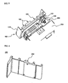
- FIGS. 1 and 2 are perspective views illustrating the rear and front of a battery module interface according to a preferred embodiment of the present invention, respectively.
- the battery module interface 100 is constructed in a structure in which a printed circuit board 150 and a sheathing plate 110 are coupled to each other, power connectors 131 and 141 and a communication connector 121 ('rear connectors'), for connection with a battery module, are formed at the rear of the printed circuit board 150, and power connectors 132 and 142 and a communication connector 122 ('front connectors'), for connection with an external circuit, are formed at the front of the printed circuit board 150.
- the rear connectors include the power connectors 131 and 141 and the communication connector 121.
- the rear connectors are electrically connected and mechanically coupled to the battery module in a direct fashion.
- the front connectors are connected to the external circuit.
- the power connectors 132 and 142 i.e., the cathode connector 132 and the anode connector 142, are spaced a large distance from each other such that the connection between the power connectors 132 and 142 and the external circuit is easily performed.
- the sheathing plate 110 is bent such that the sheathing plate 110 covers opposite sides of the printed circuit board 150. Also, the sheathing plate 110 has an opening, through which the rear connectors 121, 131, and 141 of the printed circuit board 150 are exposed to the outside.
- a switching board is constructed in a structure in which a rectangular heat dissipation structure 270 is mounted on a printed circuit board (PCB) 260 while the rectangular heat dissipation structure 270 is connected to six field effect transistor (FET) elements 272, which are switching elements.
- PCB printed circuit board
- FET field effect transistor
- the heat dissipation structure 270 is constructed in a structure in which the FET elements 272 are coupled to opposite side frames of the heat dissipation structure 270, and a plurality of heat dissipation ribs 271 protrude upward from a main frame integrally connected to the side frames.
- a connector supporting member 250 At the left side of the heat dissipation structure 270 is formed a connector supporting member 250, which extends in the longitudinal direction of the battery module 200.
- a communication connector 241 and a power connector 242 through which the battery module 200 is connected to the rear connectors of the battery module interface.
- FIGS. 4 and 5 are partially enlarged views illustrating a process for mounting the battery module interface according to the preferred embodiment of the present invention to one side of the battery module.
- the rear connectors 121, 131, and 141 of the battery module interface 100 are electrically connected and mechanically coupled to the battery module in a direct fashion.
- the battery module interface 100 is mounted to the rear of the battery module at which a third circuit unit of the battery module 200 is mounted.
- the power connectors (not shown) and the communication connector 240 ('module connectors') which are connected to the rear connectors 121, 131, and 141 of the battery module interface 100, are mounted on the ' ⁇ '-shaped connector supporting member 250.
- the electrical connection and mechanical coupling between the battery module 200 and the battery module interface 100 are accomplished by the module connectors.
- FIG. 5 illustrates the battery module interface 100 mounted to the rear of the battery module 200.
- FIGS. 6 and 7 are perspective views of the connector supporting member.
- the connector supporting member 250 is an insulative member formed generally in the shape of ' ⁇ '.
- the module connectors (not shown) are mounted to the inside of the connector supporting member, which is directed toward the battery module interface (not shown).
- the connector supporting member 250 is provided at the rear thereof with coupling protrusions 252, by which the connector supporting member 250 is mechanically coupled to the battery module (not shown).
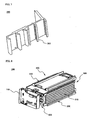
- FIG. 8 is a perspective view illustrating the battery module interface according to the preferred embodiment of the present invention mounted to the battery module.
- the battery module 200 includes an upper case 220, a lower case 230, a plurality of unit cells 210, a first circuit unit 300, a second circuit unit 400, and a third circuit unit 500.
- the unit cells 210 are stacked between the upper case 220 and the lower case 230, which are separated from each other.
- the first circuit unit 300 is located at the front of the battery module 200
- the second circuit unit 400 is located at the bottom of the battery module 200
- the third circuit unit 500 is located at the rear of the battery module 200.
- the number of the unit cells 210, which are stackable, is not limited by the upper case 220 or the lower case 230. Consequently, it is possible to easily design the battery module 200, such that the battery module 200 has a desired electrical capacity and output, by modifying the first circuit unit 300 and the third circuit unit 500 depending upon the number of the stacked unit cells 210. Also, the unit cells 210 are exposed to the outside, and therefore, heat dissipation is efficiently accomplished during the charge and discharge of the unit cells 210.
- the first circuit unit 300 is mounted to one side of the battery module 200 adjacent to electrode terminals of the unit cells 210.
- the first circuit unit 300 includes a sensing board assembly for connecting the unit cells 210 in parallel or series with each other and detecting the voltages of the respective unit cells 200 according to the present invention.
- the unit cells 210 are electrically connected to the second circuit unit 400, which is mounted at the bottom of the upper case 220, via the first circuit unit 300.
- the operation of the battery module 200 is controlled by a main board assembly of the second circuit unit 400.
- the third circuit unit 500 which is electrically connected to the second circuit unit 400, is mounted to the other side opposite to the side of the battery module 200 where the first circuit unit 300 is mounted.
- the third circuit unit 500 is the final element of the battery module 200, which is connected to an external device (not shown) for controlling the overcharge, overdischarge, and overcurrent of the unit cells.
- the control of the overcharge, overdischarge, and overcurrent of the unit cells may be performed by the switching elements (not shown), such as the FET elements, included in the third circuit unit 500.
- FIG. 9 is a perspective view illustrating a plurality of stacked battery modules, one of which is shown in FIG. 8 . It is possible to stack two or more battery modules 200 in the height direction and/or in the lateral direction.
- the structure of FIG. 9 is one example of various structures that can be embodied according to the present invention. Consequently, it should be interpreted that portions which can be easily invented, by those skilled in the art to which the present invention pertains, based on the disclosure of the present invention, fall under the protection scope of the present invention.
- the battery module interface according to the present invention may be mounted to each battery module, whereby the degree of freedom in arrangement of the battery modules is maximized. According to circumstances, however, the battery module interface according to the present invention may be mounted to two or more integrated battery modules according to the arrangement pattern of the battery modules. Alternatively, one battery module interface may be mounted to all the integrated battery modules.
- the battery module interface according to the present invention may be mounted to the two or more integrated battery modules, as described above, the electrical connection between the battery modules may be performed by the printed circuit board on the battery module interface without using additional wires. Consequently, it is possible to accomplish both the electrical connection and the mechanical coupling between a plurality of battery modules by mounting one battery module interface to the plurality of battery modules.
- the battery modules 200 are stacked such that two battery modules 200 are stacked in the vertical direction and two battery modules 200 are stacked in the lateral direction.
- the electrical connection between the battery modules 200 is accomplished by the connection between the cathode connectors 132 and the anode connectors 142 of the battery module interfaces 100. The detailed examples of the electrical connection between the battery modules will be described below with reference to FIGS. 10 to 12 .
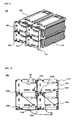
- FIGS. 10 to 12 are front views typically illustrating various electrical connection structures of a battery module assembly according to a preferred embodiment of the present invention.
- FIG. 11 illustrates a structure in which four battery modules 200 are connected in series with each other. Specifically, the cathode connectors 132 and the anode connectors 142 of the four battery modules 200 are connected to each other. In this case, the cathode connector 132 of the lower left battery module 200 and the anode connector 142 of the lower right battery module 200 serve as the external output terminals of the battery module assembly 600.
- FIG. 12 illustrates a structure in which four battery modules 200 are connected in parallel with each other.
- the electrode connectors, having the same polarity, of the four battery modules 200 are connected to each other, and the connection line between the cathode connectors and the connection line between the anode connectors are connected in parallel with each other.
- the battery module assembly 600 is constructed in a structure in which all the four battery modules 200 are connected in parallel with each other.
- the battery module having the battery module interface according to the present invention mounted thereto, is applicable to middle- or large-sized battery modules, such as electric bicycles, electric vehicles, hybrid electric vehicles, uninterruptible power supplies (UPS), idle reduction devices, and energy storage devices.
- middle- or large-sized battery modules such as electric bicycles, electric vehicles, hybrid electric vehicles, uninterruptible power supplies (UPS), idle reduction devices, and energy storage devices.
- UPS uninterruptible power supplies
Landscapes
- Chemical & Material Sciences (AREA)
- Chemical Kinetics & Catalysis (AREA)
- Electrochemistry (AREA)
- General Chemical & Material Sciences (AREA)
- Engineering & Computer Science (AREA)
- Manufacturing & Machinery (AREA)
- Microelectronics & Electronic Packaging (AREA)
- Battery Mounting, Suspending (AREA)
- Secondary Cells (AREA)
Abstract
Description
- The present invention relates to a battery module interface that is capable of effectively accomplishing the electrical connection and communication between battery modules, and, more particularly, to a battery module interface including a printed circuit board having power connectors and a communication connector formed at the rear thereof for connection with a battery module and power connectors and a communication connector formed at the front thereof for connection with an external circuit, and a sheathing plate surrounding the printed circuit board from the rear of the printed circuit board such that the rear connectors are exposed to the outside. Also, the present invention relates to a battery module having the battery module interface mounted thereto, and a middle- or large-sized battery pack including a plurality of battery modules.
- Recently, a secondary battery, which can be charged and discharged, has been widely used as an energy source for wireless mobile devices. Also, the secondary battery has attracted considerable attention as a power source for electric vehicles (EV) and hybrid electric vehicles (HEV), which have been developed to solve problems, such as air pollution, caused by existing gasoline and diesel vehicles using fossil fuel.
- Small-sized mobile devices use one or several battery cells for each device. On the other hand, middle- or large-sized devices, such as vehicles, use a middle- or large-sized battery module having a plurality of battery cells electrically connected with each other because high output and large capacity are necessary for the middle- or large-sized devices.
- Preferably, the middle- or large-sized battery module is manufactured with small size and small weight if possible. For this reason, a prismatic battery or a pouch-shaped battery, which can be stacked with high integration and has a small weight to capacity ratio, is usually used as a battery cell of the middle- or large-sized battery module. Especially, much interest is currently generated in the pouch-shaped battery, which uses an aluminum laminate sheet as a sheathing member, because the weight of the pouch-shaped battery is small, the manufacturing costs of the pouch-shaped battery are low, and it is easy to modify the shape of the pouch-shaped battery.
- For the middle- or large-sized battery module to provide the output and capacity required by a specific apparatus or device, it is necessary for the middle- or large-sized battery module to be constructed in a structure in which a plurality of battery cells are electrically connected in series or parallel with each other, and the battery cells are stable against an external force.
- Consequently, when a middle- or large-sized battery module is constructed using a plurality of battery cells, a plurality of members for mechanical coupling and electrical connection between the battery cells are generally needed, and, as a result, a process for assembling the mechanical coupling and electrical connection members is very complicated. Furthermore, there is needed a space for coupling, welding, or soldering the mechanical coupling and electrical connection members, with the result that the total size of the system is increased. The increase in size of the system is not preferred in the aspect of the spatial limit of an apparatus or device in which the middle- or large-sized battery module is mounted. Furthermore, the middle- or large-sized battery module must be constructed in a more compact structure in order that the middle- or large-sized battery module is effectively mounted in a limited inner space, such as a vehicle.
- Consequently, there is a high necessity for a battery module assembly that is more compact, is structurally stable, and is capable of effectively accomplishing the electrical connection and communication between battery modules constituting the battery module assembly, as previously described.
-
WO 01/73914 A2 -
US 5,721,669 A describes a gear-driven docking apparatus for removable mass-storage drives comprising a guide rail, mounted inside a computer chassis, and a drive carrier, bearing a mass-storage drive. The drive carrier includes an alignment groove for slidingly receiving the guide rail and a gear train for engaging a rack profile formed at the proximal end of the guide rail. The rack profile and the gear train incorporate a mechanism that provides gear-and-rack synchronization under all operating conditions. Data and power connectors of the mass-storage drive are terminated to a printed circuit board that is movably attached to the drive carrier. The circuit board merges the separate power and data connectors into a single docking connector having registration pins. - Aspects of the present invention are defined in claims 1 and 12 below. The dependent claims are directed to optional and preferred features.
- Therefore, the present invention has been made to solve the above problems, and other technical problems that have yet to be resolved.
- Specifically, it is an object of the present invention to provide a battery module interface having a compact structure in which the battery module interface is stably mounted in a limited space, such as a vehicle and that is capable of effectively accomplishing the electrical connection and communication between battery modules.
- It is another object of the present invention to provide a battery module having the battery module interface mounted thereto and a middle- or large-sized battery pack including a plurality of battery modules.
- In accordance with one aspect of the present invention, the above and other objects can be accomplished by the provision of a battery module interface mounted to one side of a battery module including a plurality of plate-shaped secondary battery cells ('battery cells'), which can be charged and discharged, for performing the electrical connection between the battery module and an external circuit, wherein the battery module interface includes a printed circuit board having power connectors and a communication connector ('rear connectors') formed at the rear thereof for connection with the battery module and power connectors and a communication connector ('front connectors') formed at the front thereof for connection with the external circuit, and a sheathing plate having an opening, through which the rear connectors of the printed circuit board are exposed to the outside, the sheathing plate being coupled to the printed circuit board such that the sheathing plate surrounds the printed circuit board from the rear of the printed circuit board.
- The power connectors and the communication connector formed at the rear of the printed circuit board are electrically connected and mechanically coupled to the battery module in a direct fashion. Consequently, the power connectors and the communication connector formed at the rear of the printed circuit board may be adjacent to each other such that the connection and coupling between the battery module interface and one side of the battery module is easily performed.
- The power connectors formed at the front of the printed circuit board include a cathode connector and an anode connector. The connection between the power connectors and the external circuit may be accomplished by soldering, mechanical coupling, or welding. Preferably, therefore, the cathode connector and the anode connector are spaced a large distance from each other such that the connection between the power connectors and the external circuit is easily performed.
- The sheathing plate is bent in the direction opposite to the battery module, i.e., such that the sheathing plate covers opposite sides of the printed circuit board. This is to protect the printed circuit board from external impacts, and, at the same time, to disturb the heat dissipation of the heat dissipation structure.
- In accordance with another aspect of the present invention, there is provided a battery module having the battery module interface mounted thereto. The battery module may include plates between which a plurality of unit cells, i.e., battery cells that can be charged and discharged, are stacked and a circuit unit for controlling the operation of the unit cells.
- The plates are not particularly restricted so long as the plates are constructed in a structure in which the unit cells are stacked. The plates may be constructed in a case structure (an upper case and a lower case) having a receiving part corresponding to the size of the battery cells such that the battery cells are easily mounted in the receiving part. Preferably, the cases are constructed in a separate structure in which the cases cover the top and bottom of the stacked battery cells, respectively.
- In a preferred embodiment, the battery module according to the present invention includes a rectangular lower case including an upper end receiving part in which a plurality of battery cells are sequentially stacked, a rectangular upper case including a lower end receiving part for covering the top of the battery cells stacked on the lower case, a first circuit unit for electrically connecting the stacked battery cells to each other, the first circuit unit including a sensing board assembly for detecting the voltage and/or current of the battery cells, a second circuit unit electrically connected to the first circuit unit, the second circuit unit including a main board assembly for controlling the overall operation of the battery module, and a third circuit unit electrically connected to the second circuit unit, the third circuit unit being connected to an external output terminal while preventing the overcurrent.
- The battery module according to the present invention is constructed generally in a compact structure. Specifically, the width of the completed battery module is almost equal to or slightly greater than that of each unit cell. The length of the battery module is greater, by the widths of the first circuit unit and the third circuit unit mounted to the opposite sides of the battery module, than that of each unit cell. The thickness of the battery module is the sum of the thickness of the stacked unit cells, the thickness of the second circuit unit, and the thicknesses of the upper and lower cases. Consequently, the battery module according to the present invention has a size less than that of any conventional battery modules, and therefore, the battery module according to the present invention is effectively mounted in an external apparatus or device to which the battery module according to the present invention will be applied.
- Each unit cell is not particularly restricted so long as the unit cell is a secondary battery that can be charged and discharged. For example, a lithium secondary battery, a nickel-metal hydride (Ni-MH) battery, a nickel-cadmium (Ni-Cd) battery may be used as the unit cell. Among them, the lithium secondary battery is preferably used as the unit cell because the lithium secondary battery exhibits a high output to weight ratio. Based on its shape, the lithium secondary battery may be classified as a cylindrical battery, a prismatic battery, or a pouch-shaped battery. Among them, the prismatic battery or the pouch-shaped battery are preferably used as the unit cell because the prismatic battery or the pouch-shaped battery can be stacked with high integration. More preferably, the pouch-shaped battery is used as the unit cell because the weight of the pouch-shaped battery is very small.
- In the battery module according to the present invention, the upper case and the lower case are separated from each other. Consequently, when the capacity and output of the battery module need to be changed according to circumstances, it is possible to add or remove the unit cells between the upper case and the lower case, and therefore, the flexible design of the battery module is possible.
- The overall size of the upper case and the lower case is approximately equivalent to that of each unit cell. Consequently, the upper end receiving part of the lower case and the lower end receiving part of the upper case, in which the unit cells are received, correspond to the size of the cell body of each unit cell.
- The first circuit unit is mounted to the front of the battery module adjacent to electrode leads of the unit cells. The first circuit unit includes connection terminals for connecting the unit cells in parallel or series with each other, the sensing board assembly of the first circuit unit receives voltage and current signals from the respective unit cells and detects the temperature of the battery. The temperature of the battery may be measured by the sensing board assembly as the overall temperature of the battery module.
- The construction of the connection members is not particularly restricted so long as the unit cells are connected in parallel or series with each other by the connection members. Preferably, a safety element, for interrupting current when overcurrent or overheat is generated, is connected between the connection members. The safety element may be, for example, a fuse, a bimetal, or a positive temperature coefficient (PTC) element.
- Preferably, the sensing board assembly is made of a printed circuit board (PCB), and the sensing board assembly is electrically connected to the respective unit cells.
- The unit cells are electrically connected to the second circuit unit, which is mounted at the lower end receiving part of the upper case, via the first circuit unit. The operation of the battery module is controlled by the main board assembly of the second circuit unit.
- The third circuit unit, which is electrically connected to the second circuit unit, is mounted to the other side opposite to the side of the battery module where the first circuit unit is mounted. The third circuit unit is the final element of the battery module, which is connected to an external device for controlling the overcharge, overdischarge, and overcurrent of the unit cells. The control of the overcharge, overdischarge, and overcurrent of the unit cells may be performed by a switching element included in the third circuit unit.
- Preferably, the main board assembly is made of a PCB. Consequently, the main board assembly of the second circuit unit has a specific strength sufficient to protect the unit cells against the external impacts. According to circumstances, therefore, a safety member, including the second circuit unit, may be mounted only to the upper case.
- The battery module is constructed in a structure in which the circuit units for controlling the operation of the unit cells are connected to each other such that the circuit units surround the battery module. Consequently, the overall size of the battery module is greatly reduced.
- The third circuit unit includes a switching element for controlling the overcurrent during the charge and discharge of the battery cells, and the third circuit unit is mounted at the rear of the battery module opposite to electrode terminals of the battery cells.
- The switching element is connected in series to the unit cells, constituting the battery module, for controlling the current flowing in the unit cells. The switching element is connected to a protection circuit for detecting the voltage and/or the current of the unit cells to control the switching element. The switching element is not particularly restricted so long as the switching element controls overcharge, overdischarge, and overcurrent of the unit cells. For example, an FET element or a transistor may be used as the switching element. Preferably, the FET element is used as the switching element.
- As described above, the third circuit unit includes the switching element for controlling the overcurrent during the charge and discharge of the battery cells. The switching element is connected to a control circuit for detecting the voltage and/or the current of the unit cells to control the switching element. The switching element is controlled to be on or off according to a signal outputted from the control circuit.
- The battery module interface is mounted to the rear of the battery module where the third circuit unit is located. The battery module is provided at one side of the rear thereof with a connection member including power connectors and a communication connector ('module connectors') connected to the rear connectors of the battery module interface, whereby the electrical connection and mechanical coupling between the battery module and the battery module interface are accomplished.
- The connection member is constructed in a structure in which the module connectors are mounted on a '¬'-shaped insulative member. Specifically, the connection member is constructed in a structure in which the module connectors are mounted on a '¬'-shaped supporting member toward the battery module interface, and the supporting member is provided at the rear thereof with coupling protrusions, by which the supporting member is mechanically coupled to the battery module. Also, the module connectors are coupled to the connectors of the battery module interface. Consequently, the third circuit unit may be located at one side of the rear of the battery module, and the connection member may be spaced a predetermined distance from the third circuit unit. Preferably, the connection member is located at least at the same height as the outermost protruding portion at the front of the battery module.
- The first circuit unit is mounted to the front of the battery module adjacent to the electrode leads of the unit cells. The first circuit unit includes an anode and a cathode. The anode and the cathode of the first circuit unit are electrically connected to the anode connector and the cathode connector of the connection member. The connection structure between the anode and the cathode of the first circuit unit and the anode connector and the cathode connector of the connection member is not restricted. Preferably, however, the connection between the anode and the cathode of the first circuit unit and the anode connector and the cathode connector of the connection member is accomplished by wires. During the electrical connection between the first circuit unit and the power connectors, at least one connection route passes through the third circuit unit, whereby it is possible to control the overvoltage and/or overcurrent of the battery module. Preferably, the anode of the first circuit unit is connected to the anode connector of the connection member by a wire, and the cathode of the first circuit unit is connected to the cathode connector of the connection member, via the third circuit unit, by a wire.
- Also, a communication port, for voltage detection, of the sensing board assembly of the first circuit unit is connected to the communication connector of the connection member, via the second circuit unit, whereby it is possible to sense and control the overall voltage and/or current and temperature of the battery module as well as the voltage and/or current and temperature of the respective stacked battery cells.
- In accordance with a further aspect of the present invention, there is provided a middle- or large-sized battery system having a high output and large capacity, which includes a plurality of battery modules. The battery modules may be connected in series and/or parallel with each other through their battery module interfaces. Consequently, the flexible design of the battery system according to a desired output and capacity is possible.
- The range of the high output and large capacity is not particularly restricted. For example, the battery system according to the present invention may be used as a power source for vehicles, such as electric bicycles (E-bike), electric motorcycles, electric vehicles, and hybrid electric vehicles, a charging and discharging power source for uninterruptible power supplies (UPS), idle reduction devices, and energy storage devices, or a power source for various applications and products, including industrial or domestic apparatuses. Preferably, the battery system according to the present invention is used as a charging and discharging power source for electric vehicles by virtue of its compact structure.
- The above and other objects, features and other advantages of the present invention will be more clearly understood from the following detailed description taken in conjunction with the accompanying drawings, in which:
-
FIGS. 1 and 2 are perspective views illustrating the structure of a battery module interface according to a preferred embodiment of the present invention; -
FIG. 3 is a partially enlarged view illustrating a battery module before the battery module interface is mounted to the battery module; -
FIGS. 4 and5 are partially enlarged views illustrating a process for mounting the battery module interface ofFIG. 1 to one side of the battery module; -
FIGS. 6 and7 are perspective views illustrating a supporting member having a battery module connector mounted thereon; -
FIG. 8 is a perspective view illustrating the battery module interface mounted to one side of the battery module; -
FIG. 9 is a perspective view illustrating a plurality of stacked battery modules, one of which is shown inFIG. 8 ; and -
FIGS. 10 to 12 are typical views illustrating various electrical connections between the stacked battery modules ofFIG. 9 . -
100: battery module interface 200: battery module 210: unit cell 300: first circuit unit 400: second circuit unit 500: third circuit unit 600: battery module assembly - Now, preferred embodiments of the present invention will be described in detail with reference to the accompanying drawings. It should be noted, however, that the scope of the present invention is not limited by the illustrated embodiments.
-
FIGS. 1 and 2 are perspective views illustrating the rear and front of a battery module interface according to a preferred embodiment of the present invention, respectively. - Referring to
FIGS. 1 and 2 , thebattery module interface 100 is constructed in a structure in which a printedcircuit board 150 and asheathing plate 110 are coupled to each other,power connectors circuit board 150, andpower connectors circuit board 150. - The rear connectors include the
power connectors communication connector 121. The rear connectors are electrically connected and mechanically coupled to the battery module in a direct fashion. - The front connectors are connected to the external circuit. Especially, the
power connectors cathode connector 132 and theanode connector 142, are spaced a large distance from each other such that the connection between thepower connectors - The
sheathing plate 110 is bent such that thesheathing plate 110 covers opposite sides of the printedcircuit board 150. Also, thesheathing plate 110 has an opening, through which therear connectors circuit board 150 are exposed to the outside. -
FIG. 3 is a partially enlarged rear perspective view of a battery module. - Referring to
FIG. 3 , which illustrates the rear of thebattery module 200, a switching board is constructed in a structure in which a rectangularheat dissipation structure 270 is mounted on a printed circuit board (PCB) 260 while the rectangularheat dissipation structure 270 is connected to six field effect transistor (FET)elements 272, which are switching elements. - The
heat dissipation structure 270 is constructed in a structure in which theFET elements 272 are coupled to opposite side frames of theheat dissipation structure 270, and a plurality ofheat dissipation ribs 271 protrude upward from a main frame integrally connected to the side frames. At the left side of theheat dissipation structure 270 is formed aconnector supporting member 250, which extends in the longitudinal direction of thebattery module 200. On theconnector supporting member 250 are mounted acommunication connector 241 and apower connector 242, through which thebattery module 200 is connected to the rear connectors of the battery module interface. -
FIGS. 4 and5 are partially enlarged views illustrating a process for mounting the battery module interface according to the preferred embodiment of the present invention to one side of the battery module. - Referring to these drawings, the
rear connectors battery module interface 100 are electrically connected and mechanically coupled to the battery module in a direct fashion. Thebattery module interface 100 is mounted to the rear of the battery module at which a third circuit unit of thebattery module 200 is mounted. At one side of the rear of the battery module, the power connectors (not shown) and the communication connector 240 ('module connectors'), which are connected to therear connectors battery module interface 100, are mounted on the '¬'-shapedconnector supporting member 250. The electrical connection and mechanical coupling between thebattery module 200 and thebattery module interface 100 are accomplished by the module connectors.FIG. 5 illustrates thebattery module interface 100 mounted to the rear of thebattery module 200. -
FIGS. 6 and7 are perspective views of the connector supporting member. - Referring to these drawings, the
connector supporting member 250 is an insulative member formed generally in the shape of '¬'. The module connectors (not shown) are mounted to the inside of the connector supporting member, which is directed toward the battery module interface (not shown). Theconnector supporting member 250 is provided at the rear thereof withcoupling protrusions 252, by which theconnector supporting member 250 is mechanically coupled to the battery module (not shown). -
FIG. 8 is a perspective view illustrating the battery module interface according to the preferred embodiment of the present invention mounted to the battery module. - Referring to
FIG. 8 , thebattery module 200 includes anupper case 220, alower case 230, a plurality ofunit cells 210, afirst circuit unit 300, asecond circuit unit 400, and athird circuit unit 500. Theunit cells 210 are stacked between theupper case 220 and thelower case 230, which are separated from each other. Thefirst circuit unit 300 is located at the front of thebattery module 200, thesecond circuit unit 400 is located at the bottom of thebattery module 200, and thethird circuit unit 500 is located at the rear of thebattery module 200. - Since the
upper case 220 and thelower case 230 are separated from each other, the number of theunit cells 210, which are stackable, is not limited by theupper case 220 or thelower case 230. Consequently, it is possible to easily design thebattery module 200, such that thebattery module 200 has a desired electrical capacity and output, by modifying thefirst circuit unit 300 and thethird circuit unit 500 depending upon the number of the stackedunit cells 210. Also, theunit cells 210 are exposed to the outside, and therefore, heat dissipation is efficiently accomplished during the charge and discharge of theunit cells 210. - The
first circuit unit 300 is mounted to one side of thebattery module 200 adjacent to electrode terminals of theunit cells 210. Thefirst circuit unit 300 includes a sensing board assembly for connecting theunit cells 210 in parallel or series with each other and detecting the voltages of therespective unit cells 200 according to the present invention. - The
unit cells 210 are electrically connected to thesecond circuit unit 400, which is mounted at the bottom of theupper case 220, via thefirst circuit unit 300. The operation of thebattery module 200 is controlled by a main board assembly of thesecond circuit unit 400. - The
third circuit unit 500, which is electrically connected to thesecond circuit unit 400, is mounted to the other side opposite to the side of thebattery module 200 where thefirst circuit unit 300 is mounted. Thethird circuit unit 500 is the final element of thebattery module 200, which is connected to an external device (not shown) for controlling the overcharge, overdischarge, and overcurrent of the unit cells. The control of the overcharge, overdischarge, and overcurrent of the unit cells may be performed by the switching elements (not shown), such as the FET elements, included in thethird circuit unit 500. - The
battery module interface 100 is mounted to the rear of thebattery module 200 where thethird circuit unit 500 of thebattery module 200 is located. An anode of thefirst circuit unit 300 is connected to the anode connector of the battery module interface connection member by a wire (not shown), and a cathode of thefirst circuit unit 300 is connected to the cathode connector of the battery module interface connection member, via the third circuit unit, by a wire. - Also, a communication port, for voltage detection, of the sensing board assembly of the
first circuit unit 300 is connected to the communication connector of the battery module interface connection member, via the second circuit unit. -
FIG. 9 is a perspective view illustrating a plurality of stacked battery modules, one of which is shown inFIG. 8 . It is possible to stack two ormore battery modules 200 in the height direction and/or in the lateral direction. The structure ofFIG. 9 is one example of various structures that can be embodied according to the present invention. Consequently, it should be interpreted that portions which can be easily invented, by those skilled in the art to which the present invention pertains, based on the disclosure of the present invention, fall under the protection scope of the present invention. - For example, the battery module interface according to the present invention may be mounted to each battery module, whereby the degree of freedom in arrangement of the battery modules is maximized. According to circumstances, however, the battery module interface according to the present invention may be mounted to two or more integrated battery modules according to the arrangement pattern of the battery modules. Alternatively, one battery module interface may be mounted to all the integrated battery modules. When the battery module interface according to the present invention may be mounted to the two or more integrated battery modules, as described above, the electrical connection between the battery modules may be performed by the printed circuit board on the battery module interface without using additional wires. Consequently, it is possible to accomplish both the electrical connection and the mechanical coupling between a plurality of battery modules by mounting one battery module interface to the plurality of battery modules.
- The
battery modules 200, each of which includes a plurality of stackedbattery cells 210, are stacked such that twobattery modules 200 are stacked in the vertical direction and twobattery modules 200 are stacked in the lateral direction. The electrical connection between thebattery modules 200 is accomplished by the connection between thecathode connectors 132 and theanode connectors 142 of the battery module interfaces 100. The detailed examples of the electrical connection between the battery modules will be described below with reference toFIGS. 10 to 12 . -
FIGS. 10 to 12 are front views typically illustrating various electrical connection structures of a battery module assembly according to a preferred embodiment of the present invention. - According to the circumstances, the capacity and output of the battery module according to the present invention may be flexibly changed by changing the electrical connection structure of the battery module interface. The electrical connection between the
battery modules 200 is accomplished by the electrical connection between thecathode connectors 132 and theanode connectors 142 of the battery module interfaces 100. - Referring first to
FIG. 10 , thecathode connectors 132 and theanode connectors 142 are connected to each other (132a and 142b, 132d and 132c) for thebattery modules 200 stacked in the height direction. For thebattery modules 200 stacked in the lateral direction, connectors having the same polarity are connected to each other (132b and 132c, 142s and 142d). In this case, the connection line between theanode connector upper battery modules 200 and the connection line between thecathode connectors lower battery modules 200 serve as the external output terminals of thebattery module assembly 600. As a result, thebattery module assembly 600 is constructed in a structure in which twobattery modules 200 are connected in series with each other, and twobattery modules 200 are connected in parallel with each other (2S2P). -
FIG. 11 illustrates a structure in which fourbattery modules 200 are connected in series with each other. Specifically, thecathode connectors 132 and theanode connectors 142 of the fourbattery modules 200 are connected to each other. In this case, thecathode connector 132 of the lowerleft battery module 200 and theanode connector 142 of the lowerright battery module 200 serve as the external output terminals of thebattery module assembly 600. -
FIG. 12 illustrates a structure in which fourbattery modules 200 are connected in parallel with each other. Specifically, the electrode connectors, having the same polarity, of the fourbattery modules 200 are connected to each other, and the connection line between the cathode connectors and the connection line between the anode connectors are connected in parallel with each other. As a result, thebattery module assembly 600 is constructed in a structure in which all the fourbattery modules 200 are connected in parallel with each other. - Although the preferred embodiments of the present invention have been disclosed for illustrative purposes, those skilled in the art will appreciate that various modifications, additions and substitutions are possible, without departing from the scope of the invention as defined in the accompanying claims.
- As apparent from the above description, the battery module interface according to the present invention effectively accomplishes the electrical connection and communication between the battery modules. Furthermore, the battery module interface according to the present invention is constructed in a compact structure in which the battery module interface is stably mounted in a limited space, such as a vehicle.
- Consequently, the battery module, having the battery module interface according to the present invention mounted thereto, is applicable to middle- or large-sized battery modules, such as electric bicycles, electric vehicles, hybrid electric vehicles, uninterruptible power supplies (UPS), idle reduction devices, and energy storage devices.
Claims (13)
- A battery module comprising a battery module interface mounted to the battery module; and
the battery module interface mounted to one side of the battery module including a plurality of plate-shaped secondary battery cells ('battery cells'), which can be charged and discharged, for performing the electrical connection between the battery module and an external circuit, wherein the battery module interface comprises:a printed circuit board having power connectors and a communication connector ('rear connectors') formed at the rear thereof for connection with the battery module and power connectors and a communication connector ('front connectors') formed at the front thereof for connection with the external circuit, anda sheathing plate having an opening, through which the rear connectors of the printed circuit board are exposed to the outside, the sheathing plate being coupled to the printed circuit board such that the sheathing plate surrounds the printed circuit board from the rear of the printed circuit board,wherein the sheathing plate is bent such that the sheathing plate covers opposite sides of the printed circuit board. - The battery module according to claim 1, wherein the power connectors and the communication connector formed at the rear of the printed circuit board are adjacent to each other such that the connection and coupling between the battery module interface and one side of the battery module is performed.
- The battery module according to claim 1, wherein the power connectors, i.e., the cathode connector and the anode connector, formed at the front of the printed circuit board are spaced a large distance from each other such that the connection between the power connectors and the external circuit is performed.
- The battery module according to claim 1, wherein the battery module further comprises:a rectangular lower case as the plate, including an upper end receiving part in which a plurality of battery cells are sequentially stacked,a rectangular upper case as the plate, including a lower end receiving part for covering the top of the battery cells stacked on the lower case,a first circuit unit for electrically connecting the stacked battery cells to each other, the first circuit unit including a sensing board assembly for detecting the voltage and/or current of the battery cells,a second circuit unit electrically connected to the first circuit unit, the second circuit unit including a main board assembly for controlling the overall operation of the battery module, anda third circuit unit electrically connected to the second circuit unit, the third circuit unit being connected to an external output terminal while preventing an overcurrent. H
- The battery module according to claim 4, wherein
the first circuit unit includes connection terminals for connecting the battery cells in parallel or series with each other, the sensing board assembly of the first circuit unit receives voltage and current signals from the respective battery cells and detects the temperatures of the battery cells, and the first circuit unit is mounted to the front of the battery module adjacent to electrode terminals of the battery cells,
the second circuit unit is mounted to the upper case, and
the third circuit unit includes a switching element for controlling the overcurrent during the charge and discharge of the battery cells, and the third circuit unit is mounted at the rear of the battery module opposite to the electrode terminals of the battery cells. - The battery module according to claim 5, wherein the battery module interface is mounted to the rear of the battery module where the third circuit unit is located.
- The battery module according to claim 6, wherein the battery module is provided at one side of the rear thereof with a connection member including power connectors and a communication connector ('module connectors') connected to the rear connectors of the battery module interface.
- The battery module according to claim 9, wherein an anode of the first circuit unit is connected to the anode connector of the connection member by a wire, and a cathode of the first circuit unit is connected to the cathode connector of the connection member, via the third circuit unit, by a wire.
- The battery module according to claim 7, wherein a communication port, for voltage detection, of the sensing board assembly of the first circuit unit is connected to the communication connector of the connection member, via the second circuit unit.
- The battery module according to claim 7, wherein the third circuit unit is located at one side of the rear of the battery module, and the connection member is spaced a predetermined distance from the third circuit unit.
- The battery module according to claim 7, wherein the connection member is constructed in a structure in which the module connectors are mounted on a '¬'-shaped supporting member toward the battery module interface, and the supporting member is provided at the rear thereof with coupling protrusions, by which the supporting member is mechanically coupled to the battery module.
- A middle- or large-sized battery pack having a high output and large capacity, which includes a plurality of battery modules according to claim 1.
- The battery pack according to claim 12, wherein the battery modules are connected in series and/or parallel with each other by battery module interfaces mounted to the respective battery modules.
Applications Claiming Priority (2)
| Application Number | Priority Date | Filing Date | Title |
|---|---|---|---|
| KR1020060089899A KR100863729B1 (en) | 2006-09-18 | 2006-09-18 | Battery module interface |
| PCT/KR2007/004292 WO2008035873A1 (en) | 2006-09-18 | 2007-09-06 | Battery module interface |
Publications (3)
| Publication Number | Publication Date |
|---|---|
| EP2064759A1 EP2064759A1 (en) | 2009-06-03 |
| EP2064759A4 EP2064759A4 (en) | 2012-12-12 |
| EP2064759B1 true EP2064759B1 (en) | 2013-12-25 |
Family
ID=39200673
Family Applications (1)
| Application Number | Title | Priority Date | Filing Date |
|---|---|---|---|
| EP07808085.0A Active EP2064759B1 (en) | 2006-09-18 | 2007-09-06 | Battery module interface |
Country Status (6)
| Country | Link |
|---|---|
| US (1) | US7927728B2 (en) |
| EP (1) | EP2064759B1 (en) |
| JP (1) | JP5259599B2 (en) |
| KR (1) | KR100863729B1 (en) |
| CN (1) | CN101517779B (en) |
| WO (1) | WO2008035873A1 (en) |
Families Citing this family (50)
| Publication number | Priority date | Publication date | Assignee | Title |
|---|---|---|---|---|
| JP5340676B2 (en) * | 2008-08-29 | 2013-11-13 | 三洋電機株式会社 | Battery system |
| KR101389023B1 (en) * | 2008-12-31 | 2014-04-25 | 주식회사 엘지화학 | Apparatus for sensing a voltage of cell of battery pack and connecting connector |
| JP5472570B2 (en) * | 2009-01-07 | 2014-04-16 | 三菱自動車工業株式会社 | Secondary battery voltage detector |
| WO2010113455A1 (en) * | 2009-03-31 | 2010-10-07 | 三洋電機株式会社 | Battery module, battery system, and electric vehicle |
| US8679666B1 (en) * | 2009-10-29 | 2014-03-25 | Quallion Llc | Packaging with terminal for multiple battery power system |
| EP2325919A3 (en) * | 2009-10-30 | 2011-11-30 | Sanyo Electric Co., Ltd. | Battery system and electric vehicle including the same |
| CN102097646A (en) * | 2009-10-30 | 2011-06-15 | 三洋电机株式会社 | Battery module, battery system and electric vehicle including the same |
| US8734978B2 (en) * | 2009-11-05 | 2014-05-27 | Samsung Sdi Co., Ltd. | Battery pack |
| KR101613497B1 (en) | 2009-11-23 | 2016-04-20 | 삼성에스디아이 주식회사 | Uninterruptible power supply module unit and uninterruptible power supply having the same |
| KR101108181B1 (en) | 2009-11-27 | 2012-01-31 | 삼성에스디아이 주식회사 | Battery pack |
| KR101097257B1 (en) | 2009-12-03 | 2011-12-21 | 삼성에스디아이 주식회사 | Circuit board module and battery module applying same |
| JP5566719B2 (en) * | 2010-02-15 | 2014-08-06 | 株式会社東芝 | Secondary battery device |
| US8691416B1 (en) * | 2010-02-16 | 2014-04-08 | The Boeing Company | Modular vehicular power system having a battery interface module and associated method |
| DE102010027851A1 (en) * | 2010-04-16 | 2011-10-20 | Sb Limotive Company Ltd. | Battery with a plurality of independent battery cell strings |
| CN102576839B (en) * | 2010-10-15 | 2014-12-03 | 三洋电机株式会社 | Electricity storage system |
| JP5765770B2 (en) * | 2011-03-31 | 2015-08-19 | Necエナジーデバイス株式会社 | Battery pack |
| US9356278B2 (en) | 2011-03-31 | 2016-05-31 | Nec Energy Devices, Ltd. | Battery pack |
| CN202141970U (en) * | 2011-06-21 | 2012-02-08 | 中兴通讯股份有限公司 | Terminal and interface plug |
| US9005794B2 (en) | 2011-10-21 | 2015-04-14 | Tyco Electronics Corporation | Battery connector system |
| JP6058260B2 (en) | 2011-10-28 | 2017-01-11 | 株式会社東芝 | Storage battery unit |
| US8808031B2 (en) * | 2011-12-14 | 2014-08-19 | Tyco Electronics Corporation | Battery connector system |
| DE102012101800A1 (en) * | 2012-03-02 | 2013-09-05 | ropa development GmbH | Utility network component for a utility network |
| KR20140002846A (en) | 2012-06-26 | 2014-01-09 | 삼성에스디아이 주식회사 | Battery module and testing method thereof |
| RU2569935C1 (en) | 2012-08-02 | 2015-12-10 | Ниссан Мотор Ко., Лтд. | Battery unit for automatically guided vehicle |
| KR101384636B1 (en) * | 2012-08-27 | 2014-04-14 | 인지컨트롤스 주식회사 | Sensing module for secondary battery |
| JP5352723B1 (en) * | 2012-09-05 | 2013-11-27 | 日本航空電子工業株式会社 | Electrical connector |
| WO2014045855A1 (en) * | 2012-09-20 | 2014-03-27 | Necエナジーデバイス株式会社 | Battery pack |
| CN104620413B (en) * | 2012-09-25 | 2017-07-25 | 日本碍子株式会社 | Power storage devices |
| JP5573932B2 (en) * | 2012-12-14 | 2014-08-20 | 株式会社豊田自動織機 | Battery pack |
| KR101322934B1 (en) * | 2013-05-08 | 2013-10-28 | 주식회사 이젠 | Battery module for car equiment and method of driving the same |
| KR101805757B1 (en) * | 2013-08-23 | 2017-12-07 | 주식회사 엘지화학 | Battery Module Assembly Having Protruded Communication Terminals of BMS in Front thereof |
| KR101717199B1 (en) * | 2013-08-29 | 2017-03-16 | 주식회사 엘지화학 | Battery Cell Having Connecting Protrusion for Voltage Sensing and Battery Module Comprising the Same |
| KR101636380B1 (en) | 2013-09-26 | 2016-07-05 | 주식회사 엘지화학 | Voltage Sensing Assembly and Battery Module Including the Same |
| KR20150044800A (en) | 2013-10-17 | 2015-04-27 | 주식회사 엘지화학 | Battery pack |
| JP6245946B2 (en) * | 2013-11-06 | 2017-12-13 | ヤマハ発動機株式会社 | Battery and saddle riding type electric vehicle equipped with the same |
| CN105705408A (en) | 2013-11-06 | 2016-06-22 | 雅马哈发动机株式会社 | Riding Electric Vehicle |
| JP2016181489A (en) * | 2015-03-25 | 2016-10-13 | 株式会社東芝 | Electrode for nonaqueous electrolyte secondary battery, nonaqueous electrolyte secondary battery and battery pack |
| DE102015222137B3 (en) | 2015-11-10 | 2017-02-09 | Audi Ag | High-voltage battery for a motor vehicle, method for attaching a structural unit to a housing of a high-voltage battery and motor vehicle |
| CN107403969B (en) * | 2016-05-20 | 2019-08-06 | 莫列斯有限公司 | Cell apparatus and battery connection module |
| TWM533365U (en) * | 2016-08-25 | 2016-12-01 | Formosa Electronic Ind Inc | Plug-in connection structure of stacked energy-storage battery module |
| KR102744299B1 (en) | 2017-02-03 | 2024-12-18 | 삼성에스디아이 주식회사 | Battery Module |
| WO2019037891A1 (en) * | 2017-08-22 | 2019-02-28 | Sew-Eurodrive Gmbh & Co. Kg | ENERGY STORAGE ARRANGEMENT AND VEHICLE WITH ENERGY STORAGE ARRANGEMENT |
| JP6544755B1 (en) * | 2018-10-05 | 2019-07-17 | 株式会社アイ・ディー・エクス | Battery and control method thereof |
| KR102698610B1 (en) * | 2018-11-15 | 2024-08-27 | 주식회사 엘지에너지솔루션 | Battery module |
| US11228070B2 (en) * | 2019-11-11 | 2022-01-18 | Ford Global Technologies, Llc | Efficient electric architectural layouts for electrified vehicles |
| JP7028907B2 (en) * | 2020-04-08 | 2022-03-02 | 本田技研工業株式会社 | Battery module termination device |
| JP7026160B2 (en) * | 2020-04-08 | 2022-02-25 | 本田技研工業株式会社 | Battery module termination device |
| US11848457B2 (en) | 2021-01-05 | 2023-12-19 | Xentris Wireless, Llc | Small tactical universal battery and methods of interconnection |
| US11936006B2 (en) * | 2021-05-18 | 2024-03-19 | Ford Global Technologies, Llc | Battery pack circuit board holder |
| US20260058277A1 (en) * | 2022-05-25 | 2026-02-26 | Lg Energy Solution, Ltd. | Battery module |
Family Cites Families (16)
| Publication number | Priority date | Publication date | Assignee | Title |
|---|---|---|---|---|
| US3351816A (en) * | 1965-02-04 | 1967-11-07 | Bunker Ramo | Planar coaxial circuitry |
| US4346151A (en) * | 1980-12-29 | 1982-08-24 | The Gates Rubber Company | Multicell sealed rechargeable battery |
| US5745333A (en) * | 1994-11-21 | 1998-04-28 | International Business Machines Corporation | Laminar stackable circuit board structure with capacitor |
| US5721669A (en) * | 1995-09-15 | 1998-02-24 | Apple Computer, Inc. | Gear-driven docking apparatus for removable mass-storage drives |
| US6016254A (en) * | 1996-07-15 | 2000-01-18 | Pfaff; Wayne K. | Mounting apparatus for grid array packages |
| JP3503873B2 (en) * | 1998-04-10 | 2004-03-08 | 矢崎総業株式会社 | Vehicle battery box |
| US6310783B1 (en) * | 2000-03-29 | 2001-10-30 | Powerware Corporation | Modular method and apparatus for building an uninterruptible power system (UPS) |
| JP2002101573A (en) * | 2000-09-20 | 2002-04-05 | Toshiba Battery Co Ltd | Uninterruptible power system |
| JP3516649B2 (en) * | 2000-10-04 | 2004-04-05 | 日本電信電話株式会社 | Storage battery storage cabinet and storage battery storage connection method |
| CN100477335C (en) * | 2002-01-29 | 2009-04-08 | 能源系统欧洲控股公司 | Battery and assembled rack battery system |
| GB0201917D0 (en) * | 2002-01-29 | 2002-03-13 | Hawker Batteries Ltd | Modular rack battery system |
| JP4701658B2 (en) * | 2003-10-14 | 2011-06-15 | 日産自動車株式会社 | Battery module and battery pack |
| JP2005137186A (en) * | 2003-10-31 | 2005-05-26 | Age System Kk | Charging method for small-sized electronic equipment |
| WO2006068373A1 (en) * | 2004-12-24 | 2006-06-29 | Lg Chem, Ltd. | Secondary battery module |
| KR100904373B1 (en) * | 2004-12-24 | 2009-06-25 | 주식회사 엘지화학 | Heat dissipation structure for secondary battery module, and switching board and secondary battery module comprising same |
| JP4455461B2 (en) * | 2005-09-12 | 2010-04-21 | 株式会社東芝 | Power storage system |
-
2006
- 2006-09-18 KR KR1020060089899A patent/KR100863729B1/en active Active
-
2007
- 2007-09-06 CN CN2007800344750A patent/CN101517779B/en active Active
- 2007-09-06 JP JP2009529105A patent/JP5259599B2/en active Active
- 2007-09-06 EP EP07808085.0A patent/EP2064759B1/en active Active
- 2007-09-06 US US12/441,443 patent/US7927728B2/en active Active
- 2007-09-06 WO PCT/KR2007/004292 patent/WO2008035873A1/en not_active Ceased
Also Published As
| Publication number | Publication date |
|---|---|
| KR20080025430A (en) | 2008-03-21 |
| CN101517779B (en) | 2011-07-13 |
| US20100247979A1 (en) | 2010-09-30 |
| JP2010503971A (en) | 2010-02-04 |
| EP2064759A1 (en) | 2009-06-03 |
| CN101517779A (en) | 2009-08-26 |
| JP5259599B2 (en) | 2013-08-07 |
| KR100863729B1 (en) | 2008-10-16 |
| US7927728B2 (en) | 2011-04-19 |
| EP2064759A4 (en) | 2012-12-12 |
| WO2008035873A1 (en) | 2008-03-27 |
Similar Documents
| Publication | Publication Date | Title |
|---|---|---|
| EP2064759B1 (en) | Battery module interface | |
| US8034476B2 (en) | Battery module, and middle or large-sized battery pack containing the same | |
| EP1839349B1 (en) | Sensing board assembly for secondary battery module | |
| EP2450981B1 (en) | Secondary battery module | |
| EP2064761B1 (en) | Battery module and middle or large-sized battery pack containing the same | |
| KR101815876B1 (en) | Battery pack with apparatus to prevent surge current | |
| EP3671905A1 (en) | Easier to assemble battery module including bus bar frame | |
| EP2595238B1 (en) | Battery pack having compact structure | |
| EP1834365B1 (en) | Process for preparation of secondary battery module | |
| CN102804447B (en) | Battery module including novel structural sensing member | |
| CN100588003C (en) | Secondary battery module | |
| CN116075975B (en) | A battery module including a busbar frame for efficient connector layout and a battery pack including the battery module. | |
| US20260038890A1 (en) | Battery pack | |
| KR20250085175A (en) | Busbar holder assembly, battery pack including the same and method for manufacturing busbar holder assembly | |
| US20250286189A1 (en) | Battery module and battery pack with structurally integrated arrangement for side terminal cells | |
| KR20250022427A (en) | Battery module and battery pack including the same |
Legal Events
| Date | Code | Title | Description |
|---|---|---|---|
| PUAI | Public reference made under article 153(3) epc to a published international application that has entered the european phase |
Free format text: ORIGINAL CODE: 0009012 |
|
| 17P | Request for examination filed |
Effective date: 20090317 |
|
| AK | Designated contracting states |
Kind code of ref document: A1 Designated state(s): DE FR GB IT |
|
| AX | Request for extension of the european patent |
Extension state: AL BA HR MK RS |
|
| RBV | Designated contracting states (corrected) |
Designated state(s): DE FR GB IT |
|
| DAX | Request for extension of the european patent (deleted) | ||
| A4 | Supplementary search report drawn up and despatched |
Effective date: 20121109 |
|
| RIC1 | Information provided on ipc code assigned before grant |
Ipc: H01M 2/20 20060101ALI20121105BHEP Ipc: H01M 2/34 20060101ALN20121105BHEP Ipc: H01M 10/48 20060101ALI20121105BHEP Ipc: H01M 2/10 20060101AFI20121105BHEP Ipc: H01M 10/42 20060101ALI20121105BHEP |
|
| GRAJ | Information related to disapproval of communication of intention to grant by the applicant or resumption of examination proceedings by the epo deleted |
Free format text: ORIGINAL CODE: EPIDOSDIGR1 |
|
| GRAP | Despatch of communication of intention to grant a patent |
Free format text: ORIGINAL CODE: EPIDOSNIGR1 |
|
| RIC1 | Information provided on ipc code assigned before grant |
Ipc: H01M 2/20 20060101ALI20130321BHEP Ipc: H01M 10/42 20060101ALI20130321BHEP Ipc: H01M 10/48 20060101ALI20130321BHEP Ipc: H01M 2/34 20060101ALN20130321BHEP Ipc: H01M 2/10 20060101AFI20130321BHEP |
|
| GRAP | Despatch of communication of intention to grant a patent |
Free format text: ORIGINAL CODE: EPIDOSNIGR1 |
|
| INTG | Intention to grant announced |
Effective date: 20130612 |
|
| RAP1 | Party data changed (applicant data changed or rights of an application transferred) |
Owner name: LG CHEM, LTD. |
|
| GRAS | Grant fee paid |
Free format text: ORIGINAL CODE: EPIDOSNIGR3 |
|
| GRAA | (expected) grant |
Free format text: ORIGINAL CODE: 0009210 |
|
| AK | Designated contracting states |
Kind code of ref document: B1 Designated state(s): DE FR GB IT |
|
| REG | Reference to a national code |
Ref country code: GB Ref legal event code: FG4D |
|
| REG | Reference to a national code |
Ref country code: DE Ref legal event code: R096 Ref document number: 602007034481 Country of ref document: DE Effective date: 20140213 |
|
| REG | Reference to a national code |
Ref country code: DE Ref legal event code: R097 Ref document number: 602007034481 Country of ref document: DE |
|
| PLBE | No opposition filed within time limit |
Free format text: ORIGINAL CODE: 0009261 |
|
| STAA | Information on the status of an ep patent application or granted ep patent |
Free format text: STATUS: NO OPPOSITION FILED WITHIN TIME LIMIT |
|
| 26N | No opposition filed |
Effective date: 20140926 |
|
| REG | Reference to a national code |
Ref country code: DE Ref legal event code: R097 Ref document number: 602007034481 Country of ref document: DE Effective date: 20140926 |
|
| REG | Reference to a national code |
Ref country code: FR Ref legal event code: PLFP Year of fee payment: 10 |
|
| REG | Reference to a national code |
Ref country code: FR Ref legal event code: PLFP Year of fee payment: 11 |
|
| REG | Reference to a national code |
Ref country code: FR Ref legal event code: PLFP Year of fee payment: 12 |
|
| REG | Reference to a national code |
Ref country code: DE Ref legal event code: R079 Ref document number: 602007034481 Country of ref document: DE Free format text: PREVIOUS MAIN CLASS: H01M0002100000 Ipc: H01M0050200000 |
|
| P01 | Opt-out of the competence of the unified patent court (upc) registered |
Effective date: 20230408 |
|
| REG | Reference to a national code |
Ref country code: GB Ref legal event code: 732E Free format text: REGISTERED BETWEEN 20230824 AND 20230831 |
|
| REG | Reference to a national code |
Ref country code: DE Ref legal event code: R081 Ref document number: 602007034481 Country of ref document: DE Owner name: LG ENERGY SOLUTION, LTD., KR Free format text: FORMER OWNER: LG CHEM, LTD., SEOUL, KR |
|
| PGFP | Annual fee paid to national office [announced via postgrant information from national office to epo] |
Ref country code: DE Payment date: 20250820 Year of fee payment: 19 |
|
| PGFP | Annual fee paid to national office [announced via postgrant information from national office to epo] |
Ref country code: IT Payment date: 20250822 Year of fee payment: 19 |
|
| PGFP | Annual fee paid to national office [announced via postgrant information from national office to epo] |
Ref country code: GB Payment date: 20250820 Year of fee payment: 19 |
|
| PGFP | Annual fee paid to national office [announced via postgrant information from national office to epo] |
Ref country code: FR Payment date: 20250821 Year of fee payment: 19 |