EP2064530B1 - Multiple-sensor measuring device for on-board gauging probe - Google Patents
Multiple-sensor measuring device for on-board gauging probe Download PDFInfo
- Publication number
- EP2064530B1 EP2064530B1 EP07823843.3A EP07823843A EP2064530B1 EP 2064530 B1 EP2064530 B1 EP 2064530B1 EP 07823843 A EP07823843 A EP 07823843A EP 2064530 B1 EP2064530 B1 EP 2064530B1
- Authority
- EP
- European Patent Office
- Prior art keywords
- measuring device
- sensors
- sensor
- holding means
- fuel
- Prior art date
- Legal status (The legal status is an assumption and is not a legal conclusion. Google has not performed a legal analysis and makes no representation as to the accuracy of the status listed.)
- Active
Links
- 239000000523 sample Substances 0.000 title claims description 39
- 239000000446 fuel Substances 0.000 claims description 28
- 238000005259 measurement Methods 0.000 claims description 28
- XLYOFNOQVPJJNP-UHFFFAOYSA-N water Substances O XLYOFNOQVPJJNP-UHFFFAOYSA-N 0.000 claims description 7
- 239000000463 material Substances 0.000 claims description 5
- 238000012545 processing Methods 0.000 claims description 4
- 229920000515 polycarbonate Polymers 0.000 claims description 3
- 239000004417 polycarbonate Substances 0.000 claims description 3
- 239000002828 fuel tank Substances 0.000 claims description 2
- 239000011810 insulating material Substances 0.000 claims description 2
- 239000003990 capacitor Substances 0.000 description 3
- 238000009434 installation Methods 0.000 description 3
- 238000012423 maintenance Methods 0.000 description 3
- 230000007257 malfunction Effects 0.000 description 2
- 238000000034 method Methods 0.000 description 2
- 238000012935 Averaging Methods 0.000 description 1
- 238000009530 blood pressure measurement Methods 0.000 description 1
- 238000004891 communication Methods 0.000 description 1
- 238000011109 contamination Methods 0.000 description 1
- 238000001739 density measurement Methods 0.000 description 1
- 230000006866 deterioration Effects 0.000 description 1
- 239000012530 fluid Substances 0.000 description 1
- 230000004907 flux Effects 0.000 description 1
- 238000007689 inspection Methods 0.000 description 1
- 239000003350 kerosene Substances 0.000 description 1
- 238000004377 microelectronic Methods 0.000 description 1
- 238000005086 pumping Methods 0.000 description 1
- 230000002787 reinforcement Effects 0.000 description 1
- 230000000284 resting effect Effects 0.000 description 1
- 125000006850 spacer group Chemical group 0.000 description 1
- 239000000126 substance Substances 0.000 description 1
- 230000026676 system process Effects 0.000 description 1
- 239000012815 thermoplastic material Substances 0.000 description 1
Images


Classifications
-
- G—PHYSICS
- G01—MEASURING; TESTING
- G01F—MEASURING VOLUME, VOLUME FLOW, MASS FLOW OR LIQUID LEVEL; METERING BY VOLUME
- G01F23/00—Indicating or measuring liquid level or level of fluent solid material, e.g. indicating in terms of volume or indicating by means of an alarm
- G01F23/22—Indicating or measuring liquid level or level of fluent solid material, e.g. indicating in terms of volume or indicating by means of an alarm by measuring physical variables, other than linear dimensions, pressure or weight, dependent on the level to be measured, e.g. by difference of heat transfer of steam or water
- G01F23/26—Indicating or measuring liquid level or level of fluent solid material, e.g. indicating in terms of volume or indicating by means of an alarm by measuring physical variables, other than linear dimensions, pressure or weight, dependent on the level to be measured, e.g. by difference of heat transfer of steam or water by measuring variations of capacity or inductance of capacitors or inductors arising from the presence of liquid or fluent solid material in the electric or electromagnetic fields
- G01F23/263—Indicating or measuring liquid level or level of fluent solid material, e.g. indicating in terms of volume or indicating by means of an alarm by measuring physical variables, other than linear dimensions, pressure or weight, dependent on the level to be measured, e.g. by difference of heat transfer of steam or water by measuring variations of capacity or inductance of capacitors or inductors arising from the presence of liquid or fluent solid material in the electric or electromagnetic fields by measuring variations in capacitance of capacitors
- G01F23/268—Indicating or measuring liquid level or level of fluent solid material, e.g. indicating in terms of volume or indicating by means of an alarm by measuring physical variables, other than linear dimensions, pressure or weight, dependent on the level to be measured, e.g. by difference of heat transfer of steam or water by measuring variations of capacity or inductance of capacitors or inductors arising from the presence of liquid or fluent solid material in the electric or electromagnetic fields by measuring variations in capacitance of capacitors mounting arrangements of probes
Definitions
- the present invention relates to the field of fuel gauging systems, in particular for application in aeronautics.
- a capacitive type gauging probe comprising two electrodes in the form of cylindrical tubes arranged one inside the other in a coaxial manner. The probe is open at both ends so that the fuel freely enters the space between the electrodes. The capacity of the capacitor formed by the two electrodes depends linearly on the height of the fuel column between the two tubes. A description of such a capacitive probe can be found for example in the patent application FR-A-2582396 .
- the capacitive probes are not entirely satisfactory, however. Indeed, the value of the measured capacity is a function of the dielectric coefficient of the fuel. However, the latter varies according to the quality of the fuel and its rate of possible contamination by water, depending on the refueling.
- this system comprises a plurality of capacitive probes, called primary probes, high level detectors, low level detectors, sensors for measuring permittivity, density, temperature, etc.
- secondary a second type of gauging probe, which can be used on the ground in the event of failure of the primary probes.
- Patent documents US 4,434,657 A1 , US 5 187 979 A1 and US 4,420,976 A1 also describe measuring devices for a fuel gauging system.
- the primary purpose of the present invention is to provide a fuel gauging system for easy installation and maintenance which does not require perforation of the tank.
- a second aim of the invention is to propose a measuring device with microelectromechanical sensors (MEMS) which can be easily integrated into existing gauging systems.
- MEMS microelectromechanical sensors
- the present invention is defined by a multisensor measuring device for a fuel gauging system according to claim 1.
- Said plurality of sensors preferably comprises at least one pressure sensor and one density sensor. It can also include at least one permittivity sensor.
- said plurality of sensors comprises sensors of identical nature.
- the insert has an annular shape and has a threaded axial bore.
- the first holding means preferably consist of a first cylindrical part, coaxial with the insert, and ending at its upper part by a threaded tubular head intended to be screwed into said bore, said cylindrical part being pierced by an axial hole , from side to side.
- the second holding means are preferably constituted by a second cylindrical part, coaxial with the first, and pierced by an axial hole, right through.
- connection interface common to the various sensors can be mounted on the exterior surface of the annular film, the connection wires between said sensors and said interface then being embedded in the material of said film.
- the material of said film is advantageously polycarbonate.
- said quick fixing means comprise, on the one hand, pins mounted on one of the first and second cylindrical parts, and, on the other hand, corresponding bores in the other part, said pins being sized to forcefully engage in said corresponding bores.
- said quick fixing means comprise, on the one hand, snap-on fingers forming an integral part of one of the first and second cylindrical parts, and on the other hand, a corresponding groove in the other part , said fingers being adapted to snap into said corresponding groove.
- the gauging system may further comprise a plurality of auxiliary sensors installed in said plurality of tanks, each auxiliary sensor belonging to an assembly consisting of a high level detector, a low level detector, a water presence detector and a temperature sensor, each auxiliary sensor being connected to one of said local processors, the latter being adapted to process the measurement data coming from said auxiliary sensor.
- the auxiliary sensors are MEMS sensors.
- each MEMS sensor is advantageously mounted on the interior surface of a stirrup, the legs of which are bolted to the internal structure of the aircraft.
- the idea underlying the present invention is to use the primary capacitive probes to integrate a multi-sensor measurement device, in particular with MEMS sensors.
- the Fig. 1 shows schematically a capacitive probe 100 of the prior art which has been equipped with the multisensor measuring device 150 according to the invention.
- the capacitive probe comprises two coaxial metallic cylindrical tubes 110, 120, the outer tube 120 being fixed by means of insulating flanges 130, 140 on an internal frame of the tank at a predetermined height.
- the inner tube 110 does not descend to the lower end of the outer tube 120, so that free space is available at the base of the capacitive probe.
- the multisensor measuring device 150 advantageously engages in this available space, as will be seen more clearly below.
- the capacitive probe 100 and the multisensor measuring device 150 each have their own connector, designated by 135 and 145, respectively.
- the connection wires 141 carry low voltage signals and are preferably shielded to provide protection against electromagnetic interference, in particular against that generated by the signals passing through the connection wires 131.
- the signals from the capacitive probe 100 and the sensors of the measurement device 150 are processed by a local processor, advantageously but not necessarily installed in the measurement device itself, before being transmitted via a data bus to the central processor of the gauging system.
- the Fig. 2 represents an exploded view showing the lower part of the capacitive probe as well as the detail of the structure of the measuring device 150.
- the multi-sensor measuring device mainly comprises an insert 160, a first cylindrical part 180 and a second cylindrical part 190.
- the insert 160 is in the form of an annular part with an outside diameter substantially equal to the inside diameter of the cylindrical tube 120, and mounted forcefully inside the latter without however, distort it. Once the insert is in place, its base is flush with the lower end of the tube. The position of the insert along the axis of the capacitive probe is thus perfectly determined.
- the insert is housed under the inner cylindrical tube 110, so that the capacitive measurement is not affected by its presence. It has a threaded axial bore 161 into which a threaded tubular head 181 is screwed, forming an integral part of the first cylindrical part 180.
- the external diameter of the first cylindrical part 180 is substantially equal to the external diameter of the tube 120. It comprises at its upper part the threaded tubular head 181, intended to be screwed into the insert.
- the assembly constituted by the insert and the tube comes to rest on a shoulder 182 when the first cylindrical part is in the screwed position.
- a seal 170 can be placed, as indicated, on the shoulder 182 so as to avoid any deterioration of the tube 120 during tightening.
- the insert may have at its base a shoulder of diameter equal to or greater than the outside diameter of the tube, the base of the tube then resting directly on said shoulder.
- the outer surface of the cylindrical part 180 is preferably knurled over at least part 183 of its height in order to facilitate its tightening. As will be detailed below, this part comprises at its lower part first rapid fixing means 185 (not visible in this figure).
- the second cylindrical part 190 is also of outside diameter substantially equal to that of the tube 120 and is advantageously knurled over at least part 191 of its height.
- Second quick fixing means 195 are an integral part of the part 190 or are fixed to the upper part of the latter. The first and second quick fixing means 185 and 195 cooperate to secure the first and second cylindrical parts 180 and 190.
- the second quick fixing means 195 consist of pins arranged parallel to the axis of revolution of the second cylindrical part 190 and mounted in the upper part of the latter.
- the first quick fixing means are then constituted by bores 185 in the lower part of the first cylindrical part 180.
- the pins are dimensioned so as to be able to engage in force in the corresponding bores.
- the pins can be provided on the first cylindrical part and the bores in the second cylindrical part.
- the corresponding pins and bores are arranged in a uniform angular distribution in order to distribute the mechanical stresses during tightening.
- the second quick fixing means consist of snap-in fingers, elastically deformable, extending in one or more directions substantially parallel to the axis of revolution of the second cylindrical part.
- Each finger ends with an inclined ramp end which can engage in a circular groove arranged in the lower part of the first cylindrical part 180.
- the latching fingers can be provided on the first cylindrical part and the groove in the second cylindrical part.
- the fingers are arranged in a uniform angular distribution.
- the two cylindrical parts and, where appropriate, the rapid fixing means are advantageously made of thermoplastic material.
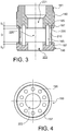
- the Fig. 3 shows an axial section of the two cylindrical parts assembled by the quick fastening means, produced here by pins 195 and corresponding bores 185.
- the first and second quick fixing means also act as spacers between the two cylindrical parts 180 and 190, so that a predetermined distance D is maintained between them.
- Circular grooves 187 and 197 are respectively arranged in the lower surface of the first cylindrical part and the upper surface of the second cylindrical part. These grooves are opposite when the two parts are secured by locking the quick fixing means.
- An annular film 200 carrying MEMS sensors 210, is mounted prisoner between the two cylindrical parts. Its thickness is chosen to be less than the width of the grooves 187 and 197 and its height is chosen to be slightly less than D + g 1 + g 2 where g 1 and g 2 are the respective depths of the two grooves. Thanks to these games, the film retains freedom of rotation inside these grooves even though it is trapped between the two cylindrical parts 180 and 190. In addition, the distance measured on a vertical axis, between the support 200 and the base of the insert 160, is perfectly determined. Thus, once the capacitive probe is installed in a tank at a predetermined height, the height of the sensors is itself perfectly known.
- the first and second cylindrical parts 180, 190 are respectively drilled by axial holes 221, 222 of sufficiently large diameters so that the fuel can freely circulate between the first and the second cylindrical parts, on the one hand, and between the first cylindrical part and the tube 120, on the other hand.
- the number and the angular extension of the rapid fixing means are chosen to be sufficiently small so that the fuel flows freely between the zone 220 and the annular film 200.
- the Fig. 4 shows in top view the second cylindrical part 190.
- the second quick fixing means (constituted here by pins), the circular groove 197 as well as the fuel circulation hole 220.
- the annular film 200 is made of an insulating material, preferably polycarbonate.
- the sensors 210 are mounted on the inner surface of the annular film so that an operator can handle the film without damaging them.
- a connection interface 213, common to the various sensors, is also mounted on the exterior surface of the annular film. It is advantageously connected to the sensors by means of wires embedded in the material of the film.
- a connector 215 can be coupled to the connection interface to connect the sensors to the local processor or to the central processor. The free rotation of the annular film 200 in the grooves 187 and 197 allows an easy connection operation between the interface 213 and the connector 215, regardless of the position of the latter.
- the second cylindrical part can be easily removed and the annular film replaced.
- the sensors 210 advantageously comprise one, and preferably several, MEMS sensor (s). Some of these sensors have the function of measuring the physico-chemical properties of the fuel, in particular its density, its viscosity or its permittivity.
- MEMS sensor a type of MEMS sensor capable of measuring the density and viscosity of a fluid.
- the permittivity measurement can be obtained from the capacitance measurement of a capacitor whose inter-armature distance or the surface is mechanically varied.
- More conventional microelectronic sensors can also be added to the annular film 200, in particular permittivity or pressure sensors.
- permittivity can be carried out from the measurement of the capacity of a standard capacitor and the measurement of pressure can be obtained from the measurement of voltage of a piezoelectric transducer.
- the sensors will be identical in nature, in other words the same sensor may be provided in several copies, for reasons of security or noise reduction by averaging the measurements.
- the primary fuel height measurement will be obtained from the capacity measurements, provided by the capacitive probe, and the permittivity measurements, provided by the multisensor device.
- the secondary measurement of fuel height will, for example, be obtained from pressure and density measurements provided by the multisensor device. This eliminates the installation of secondary MFLI probes and the disadvantages associated with them.
- the measurement data from the various sensors is transmitted over a data bus to a local processor or, failing this, to the central processor of the gauging system.
- the measurements of capacity, permittivity, pressure and density can be processed by a local processor, advantageously installed or embedded in the body of the second cylindrical part 190.
- the local processor can be deported outside this room in order to process measurement data from a plurality of capacitive probes and their associated multisensor devices.
- the local processor can simply filter and multiplex the data it receives. Alternatively, it performs the calculations for obtaining the primary and / or secondary fuel height measurements and transmits them to the central processor. Communication between the local processor and the central processor will be carried out if necessary by means of a wireless link.
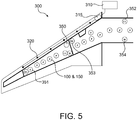
- the Fig. 5 schematically represents a fuel gauging system 300 on board an aircraft. It includes a central processor 310, possibly one or more data concentrator (s) 315, local processors 320, capacitive probes 100 on which multisensor measurement devices 150, denoted P, have been installed, as well as detailed auxiliary sensors 350 further.
- a central processor 310 possibly one or more data concentrator (s) 315, local processors 320, capacitive probes 100 on which multisensor measurement devices 150, denoted P, have been installed, as well as detailed auxiliary sensors 350 further.
- Each local processor 320 is connected to a plurality of capacitive probes (equipped with multisensor devices) as well as to the auxiliary sensors 350 located near it.
- the data processed by the local processors is possibly grouped by a data concentrator before being transmitted to the central processor.
- the central processor calculates in particular the quantity of fuel as a function, on the one hand, of the primary and / or secondary measurements, respectively supplied by the capacitive probes and the multisensor devices, and, on the other hand, of the geometry of the tanks.
- the central processor of the gauging system processes the measurements from the auxiliary sensors and transmits, if necessary, the corresponding alarms to the alarm system in flight.
- auxiliary sensors 350 are temperature sensors 351, low level detectors 352, high level detectors 353 and water presence sensors 354.
- the temperature sensors 351 are notably installed in the external tanks which are more particularly exposed to significant temperature variations. It is indeed important to warn the cockpit when the fuel temperature becomes too low or too high, this situation can affect the proper functioning of the aircraft: a too low temperature increases the viscosity of the fuel and risks leading to pumping difficulties while too high a temperature can cause vapor pockets in the engine supply system.
- low level detectors are placed in the lowest positions of the various tanks and high level detectors are arranged in positions above which an overflow occurs in the balancing tank.
- the water presence detectors are preferably placed in low positions of the tank where the water, because of its higher density than that of kerosene, is likely to accumulate. They can also advantageously be placed near certain capacitive probes, so as to allow identification of a fault in the gauging system.
- the temperature sensors, the high and low level sensors, the water presence detectors are advantageously MEMS sensors.
- the Fig. 6 illustrates one of these sensors 350, mounted on the interior surface of a stirrup 410.
- the legs 411 of the stirrup are bolted, by means of bolts 412 and anchor nuts 413, to the internal structure of the aircraft , for example, as shown on a wing span 420.
- the sensor 350 is placed sheltered from impacts between the structure of the aircraft and the stirrup 410, which considerably reduces the risk of damage during an inspection or maintenance operation.
- the connection of the sensor can be done easily by means of a multi-pin connector 415.
Landscapes
- Physics & Mathematics (AREA)
- Engineering & Computer Science (AREA)
- Power Engineering (AREA)
- Electromagnetism (AREA)
- Thermal Sciences (AREA)
- Fluid Mechanics (AREA)
- General Physics & Mathematics (AREA)
- Measurement Of Levels Of Liquids Or Fluent Solid Materials (AREA)
- Testing Or Calibration Of Command Recording Devices (AREA)
- Investigating Or Analyzing Materials By The Use Of Electric Means (AREA)
- Measurement Of Length, Angles, Or The Like Using Electric Or Magnetic Means (AREA)
Description
La présente invention concerne le domaine des systèmes de jaugeage de carburant, en particulier pour application dans l'aéronautique.The present invention relates to the field of fuel gauging systems, in particular for application in aeronautics.
On connaît de l'état de la technique plusieurs types de sondes pour mesurer la quantité de carburant dans un réservoir d'aéronef. La plus couramment utilisée est une sonde de jaugeage de type capacitif comprenant deux électrodes sous forme de tubes cylindriques disposés l'un dans l'autre de manière coaxiale. La sonde est ouverte à ses deux extrémités de sorte que le carburant pénètre librement dans l'espace entre les électrodes. La capacité du condensateur formé par les deux électrodes dépend linéairement de la hauteur de la colonne de carburant entre les deux tubes. On trouvera une description d'une telle sonde capacitive par exemple dans la demande de brevet
Les sondes capacitives ne donnent toutefois pas entière satisfaction. En effet, la valeur de la capacité mesurée est fonction du coefficient diélectrique du carburant. Or, ce dernier varie en fonction de la qualité du carburant et de son taux de contamination éventuelle par l'eau, au gré des avitaillements. Afin de prévenir les erreurs de mesure, on est conduit à prévoir un système de jaugeage complexe intégrant différents types de capteurs. En pratique, ce système comprend une pluralité de sondes capacitives, dites sondes primaires, des détecteurs de niveau haut, des détecteurs de niveau bas, des capteurs de mesure de permittivité, de densité, de température, etc. Enfin, la plupart des avions sont également équipés d'un second type de sondes de jaugeage, dites secondaires, pouvant être utilisées au sol en cas de défaillance des sondes primaires. Ces sondes secondaires utilisent typiquement un aimant solidaire d'un flotteur, l'aimant se déplaçant vis-à-vis de capteurs de flux magnétique en fonction de la hauteur de carburant. On trouvera notamment une description d'une telle sonde MFLI (Magnetic Fuel Level Indicator) dans la demande de brevet
L'installation des capteurs précités ou de sondes MFLI nécessite souvent de perforer en plusieurs points le réservoir ainsi que la paroi inférieure de l'aile. Il faut prévoir dans ce cas un montage étanche, ce qui immanquablement introduit des risques de fuite et complique les opérations de maintenance. En outre, un renfort doit être ajouté localement autour du trou perforé ce qui accroît le poids de l'appareil.The installation of the aforementioned sensors or MFLI probes often requires perforating the tank as well as the lower wall of the wing at several points. In this case, a watertight assembly must be provided, which inevitably introduces risks of leakage and complicates maintenance operations. In addition, a reinforcement must be added locally around the perforated hole which increases the weight of the device.
Les documents de brevet
Le but premier de la présente invention est de proposer un système de jaugeage de carburant d'installation et de maintenance aisées qui ne requiert pas de perforation du réservoir.The primary purpose of the present invention is to provide a fuel gauging system for easy installation and maintenance which does not require perforation of the tank.
Un but second de l'invention est de proposer un dispositif de mesure à capteurs microélectromécaniques (MEMS) qui puisse être facilement intégré dans les systèmes de jaugeage existants.A second aim of the invention is to propose a measuring device with microelectromechanical sensors (MEMS) which can be easily integrated into existing gauging systems.
La présente invention est définie par un dispositif de mesure multicapteur pour système de jaugeage de carburant selon la revendication 1.The present invention is defined by a multisensor measuring device for a fuel gauging system according to claim 1.
Ladite pluralité de capteurs comprend de préférence au moins un capteur de pression et un capteur de densité. Elle peut comprendre également au moins un capteur de permittivité.Said plurality of sensors preferably comprises at least one pressure sensor and one density sensor. It can also include at least one permittivity sensor.
Selon un exemple de réalisation, ladite pluralité de capteurs comprend des capteurs de nature identique.According to an exemplary embodiment, said plurality of sensors comprises sensors of identical nature.
Selon un exemple de réalisation, l'insert a une forme annulaire et présente un alésage axial fileté.According to an exemplary embodiment, the insert has an annular shape and has a threaded axial bore.
Les premiers moyens de maintien sont constitués de préférence par une première pièce cylindrique, coaxiale avec l'insert, et se terminant à sa partie supérieure par une tête tubulaire filetée destinée à être vissée dans ledit alésage, ladite pièce cylindrique étant percée par un trou axial, de part en part.The first holding means preferably consist of a first cylindrical part, coaxial with the insert, and ending at its upper part by a threaded tubular head intended to be screwed into said bore, said cylindrical part being pierced by an axial hole , from side to side.
Les seconds moyens de maintien sont de préférence constitués par une seconde pièce cylindrique, coaxiale avec la première, et percée par un trou axial, de part en part.The second holding means are preferably constituted by a second cylindrical part, coaxial with the first, and pierced by an axial hole, right through.
Une interface de connexion commune aux différents capteurs peut être montée à la surface extérieure du film annulaire, les fils de connexion entre lesdits capteurs et ladite interface étant alors noyés dans le matériau dudit film.A connection interface common to the various sensors can be mounted on the exterior surface of the annular film, the connection wires between said sensors and said interface then being embedded in the material of said film.
Le matériau dudit film est avantageusement du polycarbonate.The material of said film is advantageously polycarbonate.
Afin de protéger les capteurs, ceux-ci sont avantageusement montés sur la surface intérieure du film annulaire.In order to protect the sensors, they are advantageously mounted on the inner surface of the annular film.
Selon une première variante, lesdits moyens de fixation rapide comprennent, d'une part, des pions montés sur l'une des première et seconde pièces cylindriques, et, d'autre part, des alésages correspondants dans l'autre pièce, lesdits pions étant dimensionnés pour s'engager en force dans lesdits alésages correspondants.According to a first variant, said quick fixing means comprise, on the one hand, pins mounted on one of the first and second cylindrical parts, and, on the other hand, corresponding bores in the other part, said pins being sized to forcefully engage in said corresponding bores.
Selon une seconde variante, lesdits moyens de fixation rapide comprennent, d'une part, des doigts d'encliquetage faisant partie intégrante de l'une des première et seconde pièces cylindriques, et d'autre part, une rainure correspondante dans l'autre pièce, lesdits doigts étant adaptés à s'encliqueter dans ladite rainure correspondante.According to a second variant, said quick fixing means comprise, on the one hand, snap-on fingers forming an integral part of one of the first and second cylindrical parts, and on the other hand, a corresponding groove in the other part , said fingers being adapted to snap into said corresponding groove.
L'invention concerne également un système de jaugeage de carburant embarqué sur un aéronef comprenant :
- une pluralité de sondes capacitives installées à des hauteurs prédéterminées dans une pluralité de réservoirs de carburant ;
- une pluralité de dispositifs de mesure multicapteur tels que définis plus haut, lesdits dispositifs étant respectivement montés sur lesdites sondes capacitives ;
- une pluralité de processeurs locaux, chaque processeur local étant adapté à effectuer un traitement sur les données de mesure issues des sondes capacitives, des dispositifs de mesure multicapteur auxquels il est relié ;
- un processeur central adapté à calculer à partir des données ainsi traitées et des caractéristiques géométriques de ladite pluralité de réservoirs, la quantité de carburant que ceux-ci contiennent.
- a plurality of capacitive probes installed at predetermined heights in a plurality of fuel tanks;
- a plurality of multi-sensor measuring devices as defined above, said devices being respectively mounted on said capacitive probes;
- a plurality of local processors, each local processor being adapted to perform a processing on the measurement data from the capacitive probes, the multi-sensor measurement devices to which it is connected;
- a central processor adapted to calculate from the data thus processed and the geometric characteristics of said plurality of tanks, the quantity of fuel which these contain.
Le système de jaugeage peut comprendre en outre une pluralité de capteurs auxiliaires installés dans ladite pluralité de réservoirs, chaque capteur auxiliaire appartenant à un ensemble constitué d'un détecteur de niveau haut, un détecteur de niveau bas, un détecteur de présence d'eau et un capteur de température, chaque capteur auxiliaire étant relié à un desdits processeurs locaux, ce dernier étant adapté à traiter les données de mesure issues dudit capteur auxiliaire.The gauging system may further comprise a plurality of auxiliary sensors installed in said plurality of tanks, each auxiliary sensor belonging to an assembly consisting of a high level detector, a low level detector, a water presence detector and a temperature sensor, each auxiliary sensor being connected to one of said local processors, the latter being adapted to process the measurement data coming from said auxiliary sensor.
Avantageusement, les capteurs auxiliaires sont des capteurs MEMS.Advantageously, the auxiliary sensors are MEMS sensors.
Afin de protéger ces capteurs, chaque capteur MEMS est avantageusement monté sur la surface intérieure d'un étrier dont les pattes sont boulonnées sur la structure interne de l'aéronef.In order to protect these sensors, each MEMS sensor is advantageously mounted on the interior surface of a stirrup, the legs of which are bolted to the internal structure of the aircraft.
D'autres caractéristiques et avantages de l'invention apparaîtront à la lecture d'un mode de réalisation préférentiel de l'invention fait en référence aux figures jointes parmi lesquelles :
- La
Fig. 1 représente une sonde capacitive équipée d'un dispositif de mesure multicapteur selon un mode de réalisation de l'invention ; - La
Fig. 2 représente en vue éclatée un dispositif de mesure multicapteur selon un mode de réalisation de l'invention ; - La
Fig. 3 représente une coupe axiale d'une partie du dispositif de mesure multicapteur ; - La
Fig. 4 représente une vue de dessus d'une pièce du dispositif de mesure selon l'invention ; - La
Fig. 5 représente un système de jaugeage embarqué utilisant des dispositifs de mesure multicapteur selon l'invention ; - La
Fig. 6 montre le détail de montage d'un capteur auxiliaire appartenant au système de jaugeage représenté enFig. 5 .
- The
Fig. 1 represents a capacitive probe equipped with a multisensor measuring device according to an embodiment of the invention; - The
Fig. 2 shows in exploded view a multisensor measuring device according to an embodiment of the invention; - The
Fig. 3 represents an axial section of a part of the multisensor measuring device; - The
Fig. 4 shows a top view of a part of the measuring device according to the invention; - The
Fig. 5 represents an on-board gauging system using multi-sensor measuring devices according to the invention; - The
Fig. 6 shows the mounting detail of an auxiliary sensor belonging to the gauging system shown inFig. 5 .
L'idée à la base de la présente invention est d'utiliser les sondes capacitives primaires pour y intégrer un dispositif de mesure multicapteur, notamment à capteurs MEMS.The idea underlying the present invention is to use the primary capacitive probes to integrate a multi-sensor measurement device, in particular with MEMS sensors.
La
Selon une première variante, la sonde capacitive 100 et le dispositif de mesure multicapteur 150 possèdent chacun leur propre connecteur, désigné par 135 et 145, respectivement. Les fils de connexion 141 transportent des signaux de faible voltage et sont de préférence blindés pour fournir une protection contre les interférences électromagnétiques, notamment contre celles générées par les signaux transitant sur les fils de connexion 131.According to a first variant, the
Selon une seconde variante non illustrée, les signaux issus de la sonde capacitive 100 et des capteurs du dispositif de mesure 150 sont traités par un processeur local, avantageusement mais non nécessairement installé dans le dispositif de mesure lui-même, avant d'être transmis via un bus de données au processeur central du système de jaugeage.According to a second variant not shown, the signals from the
La
Le dispositif de mesure multi-capteur comprend principalement un insert 160, une première pièce cylindrique 180 et une seconde pièce cylindrique 190. L'insert 160 se présente sous la forme d'une pièce annulaire de diamètre extérieur sensiblement égal au diamètre intérieur du tube cylindrique 120, et est monté en force à l'intérieur de ce dernier sans toutefois le déformer. Une fois l'insert mis en place, sa base vient affleurer l'extrémité inférieure du tube. La position de l'insert le long de l'axe de la sonde capacitive est ainsi parfaitement déterminée. L'insert vient se loger sous le tube cylindrique intérieur 110, de sorte que la mesure capacitive n'est pas affectée par sa présence. Il présente un alésage axial fileté 161 dans lequel vient se visser une tête tubulaire filetée 181, faisant partie intégrante de la première pièce cylindrique 180.The multi-sensor measuring device mainly comprises an
Le diamètre extérieur de la première pièce cylindrique 180 est sensiblement égal au diamètre extérieur du tube 120. Elle comprend à sa partie supérieure la tête tubulaire filetée 181, destinée à être vissée dans l'insert. Ainsi, l'ensemble constitué par l'insert et le tube vient reposer sur un épaulement 182 lorsque la première pièce cylindrique est en position vissée. Avantageusement, toutefois, un joint 170 peut être placé, comme indiqué, sur l'épaulement 182 de manière à éviter toute détérioration du tube 120 lors du serrage. Alternativement, selon une variante non représentée, l'insert pourra présenter à sa base un épaulement de diamètre égal ou supérieur au diamètre extérieur du tube, la base du tube reposant alors directement sur ledit épaulement.The external diameter of the first
La surface extérieure de la pièce cylindrique 180 est de préférence moletée sur au moins une partie 183 de sa hauteur afin de faciliter son serrage. Ainsi qu'il sera détaillé plus loin, cette pièce comporte à sa partie inférieure des premiers moyens de fixation rapide 185 (non apparents sur cette figure).The outer surface of the
La seconde pièce cylindrique 190 est aussi de diamètre extérieur sensiblement égal à celui du tube 120 et est avantageusement moletée sur au moins une partie 191 de sa hauteur. Des seconds moyens de fixation rapide 195 font partie intégrante de la pièce 190 ou bien sont fixés sur la partie supérieure de cette dernière. Les premiers et seconds moyens de fixation rapide 185 et 195 coopèrent pour solidariser les première et seconde pièces cylindriques 180 et 190.The second
Selon une première variante de réalisation, les seconds moyens de fixation rapide 195 sont constitués de pions disposés parallèlement à l'axe de révolution de la seconde pièce cylindrique 190 et montés dans la partie supérieure de cette dernière. Les premiers moyens de fixation rapide sont alors constitués par des alésages 185 dans la partie inférieure de la première pièce cylindrique 180. Les pions sont dimensionnés de manière à pouvoir s'engager en force dans les alésages correspondants.According to a first alternative embodiment, the second quick fixing means 195 consist of pins arranged parallel to the axis of revolution of the second
Alternativement, les pions peuvent être prévus sur la première pièce cylindrique et les alésages dans la seconde pièce cylindrique.Alternatively, the pins can be provided on the first cylindrical part and the bores in the second cylindrical part.
De préférence, les pions et alésages correspondants sont disposés selon une distribution angulaire uniforme afin de répartir les contraintes mécaniques lors du serrage.Preferably, the corresponding pins and bores are arranged in a uniform angular distribution in order to distribute the mechanical stresses during tightening.
Selon une seconde variante de réalisation non représentée ici, les seconds moyens de fixation rapide sont constitués par des doigts d'encliquetage, élastiquement déformables, s'étendant dans une ou des direction(s) sensiblement parallèle(s) à l'axe de révolution de la seconde pièce cylindrique. Chaque doigt se termine par une extrémité en rampe inclinée pouvant venir s'engager dans une rainure circulaire aménagée dans la partie inférieure de la première partie cylindrique 180.According to a second variant embodiment, not shown here, the second quick fixing means consist of snap-in fingers, elastically deformable, extending in one or more directions substantially parallel to the axis of revolution of the second cylindrical part. Each finger ends with an inclined ramp end which can engage in a circular groove arranged in the lower part of the first
Alternativement, les doigts d'encliquetage peuvent être prévus sur la première pièce cylindrique et la rainure dans la seconde pièce cylindrique.Alternatively, the latching fingers can be provided on the first cylindrical part and the groove in the second cylindrical part.
Avantageusement, les doigts sont disposés selon une distribution angulaire uniforme.Advantageously, the fingers are arranged in a uniform angular distribution.
Enfin, d'autres types de fixation rapide équivalents peuvent être envisagés par l'homme du métier sans sortir pour autant du cadre de l'invention.Finally, other equivalent rapid fixing types can be envisaged by those skilled in the art without departing from the scope of the invention.
Les deux pièces cylindriques et, le cas échéant, les moyens de fixation rapides sont avantageusement réalisés en matière thermoplastique.The two cylindrical parts and, where appropriate, the rapid fixing means are advantageously made of thermoplastic material.
La
Les premiers et seconds moyens de fixation rapide font également office d'entretoises entre les deux pièces cylindriques 180 et 190, de sorte qu'une distance prédéterminée D est maintenue entre elles.The first and second quick fixing means also act as spacers between the two
Des gorges circulaires 187 et 197 sont respectivement aménagées dans la surface inférieure de la première pièce cylindrique et la surface supérieure de la seconde pièce cylindrique. Ces gorges sont en vis-à-vis lorsque les deux pièces sont solidarisées par verrouillage des moyens de fixation rapide.
Un film annulaire 200, portant des capteurs MEMS 210, est monté prisonnier entre les deux pièces cylindriques. Son épaisseur est choisie inférieure à la largeur des gorges 187 et 197 et sa hauteur est choisie légèrement inférieure à D+g 1+g 2 où g 1 et g 2 sont les profondeurs respectives des deux gorges. Grâce à ces jeux, le film conserve une liberté de rotation à l'intérieur de ces gorges alors même qu'il est emprisonné entre les deux pièces cylindriques 180 et 190. En outre, la distance mesurée sur un axe vertical, entre le support 200 et la base de l'insert 160, est parfaitement déterminée. Ainsi, une fois la sonde capacitive installée dans un réservoir à une hauteur prédéterminée, la hauteur des capteurs est elle-même parfaitement connue.An
Les première et seconde pièces cylindriques 180, 190 sont respectivement percées par des trous axiaux 221, 222 de diamètres suffisamment importants pour que le carburant puisse librement circuler entre la première et la seconde pièces cylindriques, d'une part, et entre la première pièce cylindrique et le tube 120, d'autre part. De surcroît, le nombre et l'extension angulaire des moyens de fixation rapide sont choisis suffisamment faibles pour que le carburant circule librement entre la zone 220 et le film annulaire 200. Ainsi, les capteurs sont assurés d'être en permanence en contact avec le carburant.The first and second
La
Le film annulaire 200 est réalisé en matière isolante, de préférence en polycarbonate. Les capteurs 210 sont montés sur la surface intérieure du film annulaire de sorte qu'un opérateur peut manipuler le film sans les endommager. Une interface de connexion 213, commune aux différents capteurs, est également montée sur la surface extérieure du film annulaire. Elle est avantageusement reliée aux capteurs au moyen de fils noyés dans la matière du film. Un connecteur 215 peut être couplé à l'interface de connexion pour relier les capteurs au processeur local ou au processeur central. La libre rotation du film annulaire 200 dans les gorges 187 et 197 permet une opération de connexion aisée entre l'interface 213 et le connecteur 215, indépendamment de la position de ce dernier.The
En cas de dysfonctionnement de l'un des capteurs, la seconde pièce cylindrique peut être aisément démontée et le film annulaire remplacé.In the event of a malfunction of one of the sensors, the second cylindrical part can be easily removed and the annular film replaced.
Les capteurs 210 comprennent avantageusement un, et préférentiellement plusieurs, capteur(s) MEMS. Certains de ces capteurs ont pour fonction de mesurer les propriétés physico-chimiques du carburant, notamment sa densité, sa viscosité ou sa permittivité. On connaît par exemple de la demande de brevet
Des capteurs microélectroniques plus classiques peuvent être également adjoints sur le film annulaire 200, notamment des capteurs de permittivité ou de pression. Ainsi, la mesure de permittivité pourra être réalisée à partir de la mesure de capacité d'un condensateur étalon et la mesure de pression pourra être obtenue à partir de la mesure de tension d'un transducteur piézoélectrique.More conventional microelectronic sensors can also be added to the
Le cas échéant, certains des capteurs seront de nature identique, autrement dit un même capteur pourra être prévu en plusieurs exemplaires, ce pour des raisons de sécurité ou de réduction de bruit par moyennage des mesures.If necessary, some of the sensors will be identical in nature, in other words the same sensor may be provided in several copies, for reasons of security or noise reduction by averaging the measurements.
La mesure primaire de hauteur de carburant sera obtenue à partir des mesures de capacité, fournies par la sonde capacitive, et celles de permittivité, fournies par le dispositif multicapteur.The primary fuel height measurement will be obtained from the capacity measurements, provided by the capacitive probe, and the permittivity measurements, provided by the multisensor device.
La mesure secondaire de hauteur de carburant sera par exemple obtenue à partir des mesures de pression et de densité, fournies par le dispositif multicapteur. On s'affranchit ainsi de l'installation de sondes secondaires MFLI et des inconvénients qui leur sont associés.The secondary measurement of fuel height will, for example, be obtained from pressure and density measurements provided by the multisensor device. This eliminates the installation of secondary MFLI probes and the disadvantages associated with them.
Les données de mesure issues des différents capteurs sont transmises sur un bus de données à un processeur local ou, à défaut, au processeur central du système de jaugeage. Les mesures de capacité, permittivité, pression et densité peuvent être traitées par un processeur local, avantageusement installé ou noyé dans le corps de la seconde pièce cylindrique 190. Alternativement, le processeur local peut être déporté hors de cette pièce afin de traiter les données de mesure issues d'une pluralité de sondes capacitives et de leurs dispositifs multicapteur associés.The measurement data from the various sensors is transmitted over a data bus to a local processor or, failing this, to the central processor of the gauging system. The measurements of capacity, permittivity, pressure and density can be processed by a local processor, advantageously installed or embedded in the body of the second
Le processeur local peut se contenter de filtrer et multiplexer les données qu'il reçoit. Selon une variante, il effectue les calculs permettant d'obtenir les mesures primaires et/ou secondaires de hauteur de carburant et les transmet au processeur central. La communication entre le processeur local et le processeur central sera réalisée le cas échéant au moyen d'une liaison sans fil.The local processor can simply filter and multiplex the data it receives. Alternatively, it performs the calculations for obtaining the primary and / or secondary fuel height measurements and transmits them to the central processor. Communication between the local processor and the central processor will be carried out if necessary by means of a wireless link.
La
Chaque processeur local 320 est relié à une pluralité de sondes capacitives (équipées de dispositifs multicapteur) ainsi qu'aux capteurs auxiliaires 350 situés à sa proximité. Les données traitées par les processeurs locaux sont éventuellement regroupées par un concentrateur de données avant d'être transmises au processeur central.Each
Le processeur central calcule notamment la quantité de carburant en fonction, d'une part, des mesures primaires et/ou secondaires, respectivement fournies par les sondes capacitives et les dispositifs multicapteur, et, d'autre part, de la géométrie des réservoirs. En outre, le processeur central du système de jaugeage traite les mesures issues des capteurs auxiliaires et transmet, le cas échéant, les alarmes correspondantes au système d'alarmes en vol.The central processor calculates in particular the quantity of fuel as a function, on the one hand, of the primary and / or secondary measurements, respectively supplied by the capacitive probes and the multisensor devices, and, on the other hand, of the geometry of the tanks. In addition, the central processor of the gauging system processes the measurements from the auxiliary sensors and transmits, if necessary, the corresponding alarms to the alarm system in flight.
Parmi les capteurs auxiliaires 350 on compte des capteurs de température 351, des détecteurs de niveau bas 352, des détecteurs de niveau haut 353 et des capteurs de présence d'eau 354.Among the
Les capteurs de température 351 sont notamment installés dans les réservoirs extérieurs qui sont plus particulièrement exposés à d'importantes variations de température. Il importe en effet d'avertir le poste de pilotage lorsque la température du carburant devient trop basse ou trop élevée, cette situation pouvant affecter le bon fonctionnement de l'avion : une température trop basse augmente la viscosité du carburant et risque de conduire à des difficultés de pompage tandis qu'une température trop élevée peut causer des poches de vapeur dans le système d'alimentation des moteurs.The
Avantageusement, des détecteurs de niveau bas sont placés dans les positions les plus basses des différents réservoirs et des détecteurs de niveau haut sont disposés en des positions au dessus desquelles se produit un débordement dans le réservoir d'équilibrage.Advantageously, low level detectors are placed in the lowest positions of the various tanks and high level detectors are arranged in positions above which an overflow occurs in the balancing tank.
Les détecteurs de présence d'eau sont de préférence placés dans des positions basses du réservoir où l'eau, du fait de sa densité plus élevée que celle du kérosène, est susceptible de s'accumuler. Ils peuvent être aussi avantageusement disposés à proximité de certaines sondes capacitives, de manière à permettre l'identification d'une défaillance dans le système de jaugeage.The water presence detectors are preferably placed in low positions of the tank where the water, because of its higher density than that of kerosene, is likely to accumulate. They can also advantageously be placed near certain capacitive probes, so as to allow identification of a fault in the gauging system.
Les capteurs de température, les capteurs de niveau haut et bas, les détecteurs de présence d'eau sont avantageusement des capteurs MEMS.The temperature sensors, the high and low level sensors, the water presence detectors are advantageously MEMS sensors.
La
On notera aussi que, du fait de la fixation de l'étrier sur la travée d'aile, le montage du capteur ne nécessite pas de perforation du réservoir. En outre, en cas de dysfonctionnement du capteur, l'étrier peut être aisément démonté et le capteur remplacé.It will also be noted that, due to the fixing of the stirrup to the wing span, the mounting of the sensor does not require perforation of the tank. In addition, in the event of a sensor malfunction, the caliper can be easily removed and the sensor replaced.
Claims (15)
- Multi-sensor measuring device for fuel gauging system, characterized in that it comprises:- an insert (160) designed to be inserted along an axis at the base of a capacitive probe (100), comprising two metallic tubes (110, 120) that are coaxial along this axis, so as to adopt a predetermined axial position relative to said probe;- an annular support (200), made of insulating material, on which is mounted a plurality of sensors (210), comprising at least one micro-electromechanical sensor;- holding means (180, 185, 190, 195) for holding said annular support at a predetermined distance from said insert along said axis, said holding means comprising first holding means (180) mounted on said insert and second holding means (190) mounted on the first by means of rapid attachment means (185, 195), the support (200) being captive between the first and second holding means when said rapid attachment means are locked, the first and second holding means (180) comprising first and second cylindrical parts respectively,
and in that a first and a second annular channel (187, 197) are created face-to-face, respectively in the lower surface of the first cylindrical part and in the upper surface of the second cylindrical part, the support (200) consisting of an annular film whose upper part is freely engaged in the first channel (187) and whose lower part is freely engaged in the second channel (197). - Measuring device according to Claim 1, characterized in that said plurality of sensors comprises at least a pressure sensor and a density sensor.
- Measuring device according to either of the preceding claims, characterized in that it comprises at least a permittivity sensor.
- Measuring device according to one of the preceding claims, characterized in that the insert (160) has a threaded axial bore (161).
- Measuring device according to Claim 4, characterized in that the first holding means (180) consists of the first cylindrical part which is coaxial with the insert and which ends, at its upper part, in a threaded tubular head (181) intended to be screwed into said bore, said cylindrical part having an axial hole (221) passing all the way through it.
- Measuring device according to Claim 5, characterized in that the second holding means (190) consists of the second cylindrical part which is coaxial with the first and which has an axial hole (222) passing all the way through it.
- Measuring device according to Claim 6, characterized in that a connection interface (213), which is common to the various sensors (210), is mounted at the outer surface of the annular film (200), the connection wires between said sensors and said interface being embedded in the material of said film.
- Measuring device according to Claim 7, characterized in that the material of said film is polycarbonate.
- Measuring device according to one of Claims 6 to 8, characterized in that the sensors are mounted on the inner surface of the annular film.
- Measuring device according to Claim 6, characterized in that said attachment means comprise, on one hand, pins mounted on one of the first and second cylindrical parts and, on the other hand, corresponding bores in the other part, said pins being dimensioned so as to engage with a force fit in said corresponding bores.
- Measuring device according to Claim 6, characterized in that said rapid attachment means comprise, on one hand, snap-fitting tabs that form an integral part of one of the first and second cylindrical parts and, on the other hand, a corresponding groove in the other part, said tabs being suitable to snap into said corresponding groove.
- Capacitive probe comprising a measuring device according to any one of the preceding claims.
- System for gauging fuel on-board an aircraft, comprising:- a plurality of capacitive probes (100) installed at predetermined heights in a plurality of fuel tanks;- a plurality of multi-sensor measuring devices (150) according to one of Claims 1 to 11, said devices being respectively mounted on said capacitive probes;- a plurality of local processors (320), each local processor being suitable for carrying out processing of the measurement data coming from the capacitive probes, of the multi-sensor measuring devices to which it is connected;- a central processing unit that is suitable for calculating, on the basis of the data processed in this manner and the geometric characteristics of said plurality of tanks, the quantity of fuel contained therein.
- Gauging system according to Claim 13, characterized in that it further comprises a plurality of auxiliary sensors (350) installed in said plurality of tanks, each auxiliary sensor belonging to an assembly consisting of a high level detector, a low-level detector, a detector for detecting the presence of water and a temperature sensor, each auxiliary sensor being connected to one of said local processors, the latter being suitable for processing the measurement data coming from the auxiliary sensor to which it is connected.
- Gauging system according to Claim 14, characterized in that the auxiliary sensors are micro-electromechanical sensors.
Applications Claiming Priority (2)
| Application Number | Priority Date | Filing Date | Title |
|---|---|---|---|
| FR0653831A FR2906027B1 (en) | 2006-09-20 | 2006-09-20 | MULTICARIZER MEASURING DEVICE FOR EMBARKETED GAUGE PROBE |
| PCT/FR2007/051948 WO2008035002A2 (en) | 2006-09-20 | 2007-09-17 | Multiple-sensor measuring device for on-board gauging probe |
Publications (2)
| Publication Number | Publication Date |
|---|---|
| EP2064530A2 EP2064530A2 (en) | 2009-06-03 |
| EP2064530B1 true EP2064530B1 (en) | 2020-02-26 |
Family
ID=37781777
Family Applications (1)
| Application Number | Title | Priority Date | Filing Date |
|---|---|---|---|
| EP07823843.3A Active EP2064530B1 (en) | 2006-09-20 | 2007-09-17 | Multiple-sensor measuring device for on-board gauging probe |
Country Status (9)
| Country | Link |
|---|---|
| US (1) | US8191419B2 (en) |
| EP (1) | EP2064530B1 (en) |
| JP (1) | JP5161224B2 (en) |
| CN (1) | CN101535781B (en) |
| BR (1) | BRPI0716737A2 (en) |
| CA (1) | CA2663702C (en) |
| FR (1) | FR2906027B1 (en) |
| RU (1) | RU2450248C2 (en) |
| WO (1) | WO2008035002A2 (en) |
Families Citing this family (11)
| Publication number | Priority date | Publication date | Assignee | Title |
|---|---|---|---|---|
| DE102005042060A1 (en) * | 2005-05-24 | 2006-11-30 | Continental Teves Ag & Co. Ohg | Reaction-free decoupling of CAN bus signals |
| EP3039388A1 (en) * | 2013-08-28 | 2016-07-06 | Sulzer Management AG | A probe for monitoring the surface level of a fluid in a vessel and a method of installing the probe in the vessel |
| RU2678760C2 (en) * | 2014-08-07 | 2019-01-31 | Зе Боинг Компани | Wireless fuel sensor system |
| US9910025B2 (en) * | 2015-06-23 | 2018-03-06 | Simmonds Precision Products, Inc. | Integrated active fuel characteristic sensor |
| EP3455596B1 (en) * | 2016-05-11 | 2020-12-09 | Siemens Healthcare Diagnostics Inc. | Quick connection for liquid level sense-enabled metering probe |
| US10126158B2 (en) * | 2016-08-22 | 2018-11-13 | The Boeing Company | Systems and methods for determining a fuel level measurement of a fuel tank using optical sensor |
| US10302598B2 (en) | 2016-10-24 | 2019-05-28 | General Electric Company | Corrosion and crack detection for fastener nuts |
| US10627280B2 (en) | 2017-04-17 | 2020-04-21 | Simmonds Precision Products | Integrated sensor unit for fuel gauging |
| EP3635347B1 (en) * | 2017-06-07 | 2021-12-22 | Stratosphere, S.A. | Fuel tank with integrated level sensors, in particular for aerial vehicles |
| CN108732223B (en) * | 2018-05-28 | 2020-05-01 | 山东博远数据服务有限公司 | Biological sensing device |
| CN110307075B (en) * | 2019-07-19 | 2024-06-04 | 昌谷汽车科技(宁波)有限公司 | Automobile water tank temperature and pressure measurement system |
Family Cites Families (8)
| Publication number | Priority date | Publication date | Assignee | Title |
|---|---|---|---|---|
| IT1123980B (en) * | 1979-02-07 | 1986-05-07 | Nira Spa | UNIVERSAL DEVICE FOR PROTECTED LEVEL AND PRESSURE MEASUREMENTS ON HAZARDOUS FLUIDS |
| US4383444A (en) * | 1980-04-21 | 1983-05-17 | Robertshaw Controls Company | Microprocessor based capacitance level detection system |
| US4420976A (en) * | 1981-09-09 | 1983-12-20 | Mcdonnell Douglas Corporation | Multiplexed true mass gaging system |
| JPS5852520A (en) * | 1981-09-25 | 1983-03-28 | Tatsuno:Kk | Liquid quantity measuring device |
| US5187979A (en) * | 1991-04-26 | 1993-02-23 | Edmark Iii Karl W | Multi-sensor probe assembly and method for fuel storage system including overflow protection means |
| JPH10115536A (en) * | 1996-10-14 | 1998-05-06 | Denso Corp | Composite sensor |
| NO310322B1 (en) * | 1999-01-11 | 2001-06-18 | Flowsys As | Painting of multiphase flow in rudder |
| US7434457B2 (en) * | 2001-03-23 | 2008-10-14 | Schlumberger Technology Corporation | Fluid property sensors |
-
2006
- 2006-09-20 FR FR0653831A patent/FR2906027B1/en not_active Expired - Fee Related
-
2007
- 2007-09-17 EP EP07823843.3A patent/EP2064530B1/en active Active
- 2007-09-17 WO PCT/FR2007/051948 patent/WO2008035002A2/en active Application Filing
- 2007-09-17 CN CN2007800341447A patent/CN101535781B/en not_active Expired - Fee Related
- 2007-09-17 CA CA2663702A patent/CA2663702C/en not_active Expired - Fee Related
- 2007-09-17 US US12/441,486 patent/US8191419B2/en active Active
- 2007-09-17 JP JP2009528766A patent/JP5161224B2/en not_active Expired - Fee Related
- 2007-09-17 BR BRPI0716737-7A2A patent/BRPI0716737A2/en not_active IP Right Cessation
- 2007-09-17 RU RU2009114819/28A patent/RU2450248C2/en not_active IP Right Cessation
Non-Patent Citations (1)
| Title |
|---|
| None * |
Also Published As
| Publication number | Publication date |
|---|---|
| US8191419B2 (en) | 2012-06-05 |
| WO2008035002A2 (en) | 2008-03-27 |
| BRPI0716737A2 (en) | 2014-11-11 |
| JP5161224B2 (en) | 2013-03-13 |
| CA2663702A1 (en) | 2008-03-27 |
| JP2010504512A (en) | 2010-02-12 |
| CA2663702C (en) | 2016-01-19 |
| RU2009114819A (en) | 2010-10-27 |
| WO2008035002A3 (en) | 2008-05-29 |
| RU2450248C2 (en) | 2012-05-10 |
| FR2906027B1 (en) | 2009-02-20 |
| FR2906027A1 (en) | 2008-03-21 |
| EP2064530A2 (en) | 2009-06-03 |
| US20090234597A1 (en) | 2009-09-17 |
| CN101535781B (en) | 2012-08-29 |
| CN101535781A (en) | 2009-09-16 |
Similar Documents
| Publication | Publication Date | Title |
|---|---|---|
| EP2064530B1 (en) | Multiple-sensor measuring device for on-board gauging probe | |
| EP3304022B1 (en) | Pressure-measuring device with improved reliability and associated calibration method | |
| CA2943691C (en) | Sealed pressure-measuring member | |
| EP3306324B1 (en) | Device for measuring flight parameters with optical deformation sensors carried by the radome of an aircraft | |
| EP2735854B1 (en) | Apparatus for measuring deformation and insertion of such an apparatus into an element | |
| FR3082224A1 (en) | MINI-TURBINE FLOWMETER AND DOWNHOLE TOOL COMPRISING A MINI-TURBINE FLOWMETER ARRAY FOR OPERATING IN A HYDROCARBON WELL. | |
| EP2347217B1 (en) | Method for calibrating a device for optical curvature monitoring | |
| FR3035209A1 (en) | MULTIFUNCTION PROBE FOR PRIMARY REFERENCES FOR AIRCRAFT, MEASUREMENT SYSTEM, AIRCRAFT AND METHOD FOR OBTAINING PHYSICAL SIZES | |
| EP3286529B1 (en) | Valve incorporating a flowmeter for measuring a flow of fluid inside same | |
| WO2011134799A1 (en) | Device for detecting the breakage of a primary path in a flight control actuator | |
| FR2896587A1 (en) | Sensor for a liquid urea solution, for reduction of nitrogen oxide in a diesel motor exhaust gas, has an immersed sensor part and a clamp holder shrouded by a holder tube with insulation to prevent short circuits | |
| EP3009819A1 (en) | System for measuring tangential force applied by a fluid with increased sensitivity | |
| EP3775795B1 (en) | Device and method for determining the phase interface level in a tank | |
| FR2966503A1 (en) | SENSOR ASSEMBLY FOR TURBINE ENGINE | |
| EP3215835B1 (en) | Capacitive measuring unit of the gas concentration in a flowing fluid | |
| EP2384970A1 (en) | Flight control system, flight control device comprising said system, and use of said system | |
| FR2942538A1 (en) | Hinge moment measuring device for e.g. control surface, of model aircraft, has connection cords connecting reference and measuring plates, where cords are arranged for forming pivoting axis fixed with respect to reference plate | |
| FR2966501A1 (en) | SHOULDER SENSOR FOR ABSORPTION OF GRAVITATIONAL LOADS | |
| EP3203198A1 (en) | An immersion detector and an aircraft | |
| WO2015091418A1 (en) | Device for measuring electric potential differences for an underwater metal structure equipped with a cathodic protection system, and associated method | |
| FR3104708A1 (en) | ANALOGUE TYPE LIQUID LEVEL SENSOR | |
| FR2853069A3 (en) | Vortex flowmeter has a sensor element formed as part of a ceramic plate on which electronic signal processing circuits are also mounted, so that flowmeter has few parts and is easy to install | |
| FR3104253A1 (en) | Sensor, system and method for detecting a liquid level in a tank | |
| FR3060119B1 (en) | CONTACTLESS DEVICE FOR MEASURING THE PRESSURE OF A FLUID CIRCULATING IN A PIPING SYSTEM | |
| EP0605298B1 (en) | Method and sensor for measuring the density of a fluid and a mass gauge using such a sensor |
Legal Events
| Date | Code | Title | Description |
|---|---|---|---|
| PUAI | Public reference made under article 153(3) epc to a published international application that has entered the european phase |
Free format text: ORIGINAL CODE: 0009012 |
|
| 17P | Request for examination filed |
Effective date: 20090316 |
|
| AK | Designated contracting states |
Kind code of ref document: A2 Designated state(s): AT BE BG CH CY CZ DE DK EE ES FI FR GB GR HU IE IS IT LI LT LU LV MC MT NL PL PT RO SE SI SK TR |
|
| DAX | Request for extension of the european patent (deleted) | ||
| 17Q | First examination report despatched |
Effective date: 20140409 |
|
| STAA | Information on the status of an ep patent application or granted ep patent |
Free format text: STATUS: EXAMINATION IS IN PROGRESS |
|
| GRAP | Despatch of communication of intention to grant a patent |
Free format text: ORIGINAL CODE: EPIDOSNIGR1 |
|
| STAA | Information on the status of an ep patent application or granted ep patent |
Free format text: STATUS: GRANT OF PATENT IS INTENDED |
|
| INTG | Intention to grant announced |
Effective date: 20190927 |
|
| GRAS | Grant fee paid |
Free format text: ORIGINAL CODE: EPIDOSNIGR3 |
|
| GRAA | (expected) grant |
Free format text: ORIGINAL CODE: 0009210 |
|
| STAA | Information on the status of an ep patent application or granted ep patent |
Free format text: STATUS: THE PATENT HAS BEEN GRANTED |
|
| AK | Designated contracting states |
Kind code of ref document: B1 Designated state(s): AT BE BG CH CY CZ DE DK EE ES FI FR GB GR HU IE IS IT LI LT LU LV MC MT NL PL PT RO SE SI SK TR |
|
| REG | Reference to a national code |
Ref country code: GB Ref legal event code: FG4D Free format text: NOT ENGLISH |
|
| REG | Reference to a national code |
Ref country code: CH Ref legal event code: EP |
|
| REG | Reference to a national code |
Ref country code: DE Ref legal event code: R096 Ref document number: 602007059911 Country of ref document: DE |
|
| REG | Reference to a national code |
Ref country code: AT Ref legal event code: REF Ref document number: 1238206 Country of ref document: AT Kind code of ref document: T Effective date: 20200315 |
|
| REG | Reference to a national code |
Ref country code: IE Ref legal event code: FG4D Free format text: LANGUAGE OF EP DOCUMENT: FRENCH |
|
| PG25 | Lapsed in a contracting state [announced via postgrant information from national office to epo] |
Ref country code: FI Free format text: LAPSE BECAUSE OF FAILURE TO SUBMIT A TRANSLATION OF THE DESCRIPTION OR TO PAY THE FEE WITHIN THE PRESCRIBED TIME-LIMIT Effective date: 20200226 |
|
| REG | Reference to a national code |
Ref country code: NL Ref legal event code: MP Effective date: 20200226 |
|
| REG | Reference to a national code |
Ref country code: LT Ref legal event code: MG4D |
|
| PG25 | Lapsed in a contracting state [announced via postgrant information from national office to epo] |
Ref country code: SE Free format text: LAPSE BECAUSE OF FAILURE TO SUBMIT A TRANSLATION OF THE DESCRIPTION OR TO PAY THE FEE WITHIN THE PRESCRIBED TIME-LIMIT Effective date: 20200226 Ref country code: BG Free format text: LAPSE BECAUSE OF FAILURE TO SUBMIT A TRANSLATION OF THE DESCRIPTION OR TO PAY THE FEE WITHIN THE PRESCRIBED TIME-LIMIT Effective date: 20200526 Ref country code: IS Free format text: LAPSE BECAUSE OF FAILURE TO SUBMIT A TRANSLATION OF THE DESCRIPTION OR TO PAY THE FEE WITHIN THE PRESCRIBED TIME-LIMIT Effective date: 20200626 Ref country code: GR Free format text: LAPSE BECAUSE OF FAILURE TO SUBMIT A TRANSLATION OF THE DESCRIPTION OR TO PAY THE FEE WITHIN THE PRESCRIBED TIME-LIMIT Effective date: 20200527 Ref country code: LV Free format text: LAPSE BECAUSE OF FAILURE TO SUBMIT A TRANSLATION OF THE DESCRIPTION OR TO PAY THE FEE WITHIN THE PRESCRIBED TIME-LIMIT Effective date: 20200226 |
|
| PG25 | Lapsed in a contracting state [announced via postgrant information from national office to epo] |
Ref country code: NL Free format text: LAPSE BECAUSE OF FAILURE TO SUBMIT A TRANSLATION OF THE DESCRIPTION OR TO PAY THE FEE WITHIN THE PRESCRIBED TIME-LIMIT Effective date: 20200226 |
|
| PG25 | Lapsed in a contracting state [announced via postgrant information from national office to epo] |
Ref country code: CZ Free format text: LAPSE BECAUSE OF FAILURE TO SUBMIT A TRANSLATION OF THE DESCRIPTION OR TO PAY THE FEE WITHIN THE PRESCRIBED TIME-LIMIT Effective date: 20200226 Ref country code: RO Free format text: LAPSE BECAUSE OF FAILURE TO SUBMIT A TRANSLATION OF THE DESCRIPTION OR TO PAY THE FEE WITHIN THE PRESCRIBED TIME-LIMIT Effective date: 20200226 Ref country code: SK Free format text: LAPSE BECAUSE OF FAILURE TO SUBMIT A TRANSLATION OF THE DESCRIPTION OR TO PAY THE FEE WITHIN THE PRESCRIBED TIME-LIMIT Effective date: 20200226 Ref country code: DK Free format text: LAPSE BECAUSE OF FAILURE TO SUBMIT A TRANSLATION OF THE DESCRIPTION OR TO PAY THE FEE WITHIN THE PRESCRIBED TIME-LIMIT Effective date: 20200226 Ref country code: EE Free format text: LAPSE BECAUSE OF FAILURE TO SUBMIT A TRANSLATION OF THE DESCRIPTION OR TO PAY THE FEE WITHIN THE PRESCRIBED TIME-LIMIT Effective date: 20200226 Ref country code: ES Free format text: LAPSE BECAUSE OF FAILURE TO SUBMIT A TRANSLATION OF THE DESCRIPTION OR TO PAY THE FEE WITHIN THE PRESCRIBED TIME-LIMIT Effective date: 20200226 Ref country code: PT Free format text: LAPSE BECAUSE OF FAILURE TO SUBMIT A TRANSLATION OF THE DESCRIPTION OR TO PAY THE FEE WITHIN THE PRESCRIBED TIME-LIMIT Effective date: 20200719 Ref country code: LT Free format text: LAPSE BECAUSE OF FAILURE TO SUBMIT A TRANSLATION OF THE DESCRIPTION OR TO PAY THE FEE WITHIN THE PRESCRIBED TIME-LIMIT Effective date: 20200226 |
|
| REG | Reference to a national code |
Ref country code: AT Ref legal event code: MK05 Ref document number: 1238206 Country of ref document: AT Kind code of ref document: T Effective date: 20200226 |
|
| REG | Reference to a national code |
Ref country code: DE Ref legal event code: R097 Ref document number: 602007059911 Country of ref document: DE |
|
| PLBE | No opposition filed within time limit |
Free format text: ORIGINAL CODE: 0009261 |
|
| STAA | Information on the status of an ep patent application or granted ep patent |
Free format text: STATUS: NO OPPOSITION FILED WITHIN TIME LIMIT |
|
| PG25 | Lapsed in a contracting state [announced via postgrant information from national office to epo] |
Ref country code: AT Free format text: LAPSE BECAUSE OF FAILURE TO SUBMIT A TRANSLATION OF THE DESCRIPTION OR TO PAY THE FEE WITHIN THE PRESCRIBED TIME-LIMIT Effective date: 20200226 Ref country code: IT Free format text: LAPSE BECAUSE OF FAILURE TO SUBMIT A TRANSLATION OF THE DESCRIPTION OR TO PAY THE FEE WITHIN THE PRESCRIBED TIME-LIMIT Effective date: 20200226 |
|
| 26N | No opposition filed |
Effective date: 20201127 |
|
| PG25 | Lapsed in a contracting state [announced via postgrant information from national office to epo] |
Ref country code: PL Free format text: LAPSE BECAUSE OF FAILURE TO SUBMIT A TRANSLATION OF THE DESCRIPTION OR TO PAY THE FEE WITHIN THE PRESCRIBED TIME-LIMIT Effective date: 20200226 Ref country code: SI Free format text: LAPSE BECAUSE OF FAILURE TO SUBMIT A TRANSLATION OF THE DESCRIPTION OR TO PAY THE FEE WITHIN THE PRESCRIBED TIME-LIMIT Effective date: 20200226 |
|
| REG | Reference to a national code |
Ref country code: DE Ref legal event code: R119 Ref document number: 602007059911 Country of ref document: DE |
|
| PG25 | Lapsed in a contracting state [announced via postgrant information from national office to epo] |
Ref country code: MC Free format text: LAPSE BECAUSE OF FAILURE TO SUBMIT A TRANSLATION OF THE DESCRIPTION OR TO PAY THE FEE WITHIN THE PRESCRIBED TIME-LIMIT Effective date: 20200226 |
|
| REG | Reference to a national code |
Ref country code: CH Ref legal event code: PL |
|
| GBPC | Gb: european patent ceased through non-payment of renewal fee |
Effective date: 20200917 |
|
| REG | Reference to a national code |
Ref country code: BE Ref legal event code: MM Effective date: 20200930 |
|
| PG25 | Lapsed in a contracting state [announced via postgrant information from national office to epo] |
Ref country code: LU Free format text: LAPSE BECAUSE OF NON-PAYMENT OF DUE FEES Effective date: 20200917 |
|
| PG25 | Lapsed in a contracting state [announced via postgrant information from national office to epo] |
Ref country code: FR Free format text: LAPSE BECAUSE OF NON-PAYMENT OF DUE FEES Effective date: 20200930 Ref country code: DE Free format text: LAPSE BECAUSE OF NON-PAYMENT OF DUE FEES Effective date: 20210401 |
|
| PG25 | Lapsed in a contracting state [announced via postgrant information from national office to epo] |
Ref country code: CH Free format text: LAPSE BECAUSE OF NON-PAYMENT OF DUE FEES Effective date: 20200930 Ref country code: BE Free format text: LAPSE BECAUSE OF NON-PAYMENT OF DUE FEES Effective date: 20200930 Ref country code: LI Free format text: LAPSE BECAUSE OF NON-PAYMENT OF DUE FEES Effective date: 20200930 Ref country code: GB Free format text: LAPSE BECAUSE OF NON-PAYMENT OF DUE FEES Effective date: 20200917 Ref country code: IE Free format text: LAPSE BECAUSE OF NON-PAYMENT OF DUE FEES Effective date: 20200917 |
|
| PG25 | Lapsed in a contracting state [announced via postgrant information from national office to epo] |
Ref country code: TR Free format text: LAPSE BECAUSE OF FAILURE TO SUBMIT A TRANSLATION OF THE DESCRIPTION OR TO PAY THE FEE WITHIN THE PRESCRIBED TIME-LIMIT Effective date: 20200226 Ref country code: MT Free format text: LAPSE BECAUSE OF FAILURE TO SUBMIT A TRANSLATION OF THE DESCRIPTION OR TO PAY THE FEE WITHIN THE PRESCRIBED TIME-LIMIT Effective date: 20200226 Ref country code: CY Free format text: LAPSE BECAUSE OF FAILURE TO SUBMIT A TRANSLATION OF THE DESCRIPTION OR TO PAY THE FEE WITHIN THE PRESCRIBED TIME-LIMIT Effective date: 20200226 |