EP2063846B1 - Support device for wheelchair - Google Patents
Support device for wheelchair Download PDFInfo
- Publication number
- EP2063846B1 EP2063846B1 EP07826392.8A EP07826392A EP2063846B1 EP 2063846 B1 EP2063846 B1 EP 2063846B1 EP 07826392 A EP07826392 A EP 07826392A EP 2063846 B1 EP2063846 B1 EP 2063846B1
- Authority
- EP
- European Patent Office
- Prior art keywords
- support device
- wheelchair
- intermediate element
- axle
- seat
- Prior art date
- Legal status (The legal status is an assumption and is not a legal conclusion. Google has not performed a legal analysis and makes no representation as to the accuracy of the status listed.)
- Not-in-force
Links
- 230000035939 shock Effects 0.000 claims description 28
- 239000006096 absorbing agent Substances 0.000 claims description 21
- 229920001971 elastomer Polymers 0.000 claims description 4
- 239000000806 elastomer Substances 0.000 claims description 3
- 241001484259 Lacuna Species 0.000 claims description 2
- 238000013016 damping Methods 0.000 claims 1
- 238000010521 absorption reaction Methods 0.000 description 5
- 230000005540 biological transmission Effects 0.000 description 2
- 230000006835 compression Effects 0.000 description 2
- 238000007906 compression Methods 0.000 description 2
- 230000003467 diminishing effect Effects 0.000 description 2
- 238000006073 displacement reaction Methods 0.000 description 2
- 239000000463 material Substances 0.000 description 2
- 241000239290 Araneae Species 0.000 description 1
- 235000004443 Ricinus communis Nutrition 0.000 description 1
- 238000005452 bending Methods 0.000 description 1
- 238000006243 chemical reaction Methods 0.000 description 1
- 238000010276 construction Methods 0.000 description 1
- 230000001419 dependent effect Effects 0.000 description 1
- 230000001747 exhibiting effect Effects 0.000 description 1
- 230000000704 physical effect Effects 0.000 description 1
- 238000005096 rolling process Methods 0.000 description 1
- 239000005060 rubber Substances 0.000 description 1
- 230000006641 stabilisation Effects 0.000 description 1
- 239000013589 supplement Substances 0.000 description 1
- 239000000725 suspension Substances 0.000 description 1
- 238000003466 welding Methods 0.000 description 1
Images






Classifications
-
- A—HUMAN NECESSITIES
- A61—MEDICAL OR VETERINARY SCIENCE; HYGIENE
- A61G—TRANSPORT, PERSONAL CONVEYANCES, OR ACCOMMODATION SPECIALLY ADAPTED FOR PATIENTS OR DISABLED PERSONS; OPERATING TABLES OR CHAIRS; CHAIRS FOR DENTISTRY; FUNERAL DEVICES
- A61G5/00—Chairs or personal conveyances specially adapted for patients or disabled persons, e.g. wheelchairs
- A61G5/10—Parts, details or accessories
- A61G5/1056—Arrangements for adjusting the seat
- A61G5/1059—Arrangements for adjusting the seat adjusting the height of the seat
-
- A—HUMAN NECESSITIES
- A61—MEDICAL OR VETERINARY SCIENCE; HYGIENE
- A61G—TRANSPORT, PERSONAL CONVEYANCES, OR ACCOMMODATION SPECIALLY ADAPTED FOR PATIENTS OR DISABLED PERSONS; OPERATING TABLES OR CHAIRS; CHAIRS FOR DENTISTRY; FUNERAL DEVICES
- A61G5/00—Chairs or personal conveyances specially adapted for patients or disabled persons, e.g. wheelchairs
- A61G5/10—Parts, details or accessories
- A61G5/1054—Large wheels, e.g. higher than the seat portion
-
- A—HUMAN NECESSITIES
- A61—MEDICAL OR VETERINARY SCIENCE; HYGIENE
- A61G—TRANSPORT, PERSONAL CONVEYANCES, OR ACCOMMODATION SPECIALLY ADAPTED FOR PATIENTS OR DISABLED PERSONS; OPERATING TABLES OR CHAIRS; CHAIRS FOR DENTISTRY; FUNERAL DEVICES
- A61G5/00—Chairs or personal conveyances specially adapted for patients or disabled persons, e.g. wheelchairs
- A61G5/10—Parts, details or accessories
- A61G5/1078—Parts, details or accessories with shock absorbers or other suspension arrangements between wheels and frame
-
- Y—GENERAL TAGGING OF NEW TECHNOLOGICAL DEVELOPMENTS; GENERAL TAGGING OF CROSS-SECTIONAL TECHNOLOGIES SPANNING OVER SEVERAL SECTIONS OF THE IPC; TECHNICAL SUBJECTS COVERED BY FORMER USPC CROSS-REFERENCE ART COLLECTIONS [XRACs] AND DIGESTS
- Y10—TECHNICAL SUBJECTS COVERED BY FORMER USPC
- Y10S—TECHNICAL SUBJECTS COVERED BY FORMER USPC CROSS-REFERENCE ART COLLECTIONS [XRACs] AND DIGESTS
- Y10S297/00—Chairs and seats
- Y10S297/04—Wheelchair
Definitions
- the present invention relates to a support device for supporting a seat on an axle of a wheelchair and to a wheelchair comprising the device.
- the present invention seeks to improve comfort for wheelchair users and in particular to solve the problem of shock loads transmission into the spinal and skeleton parts of the human body. Furthermore, the present invention seeks to provide devices and components for wheelchairs that take individual preferences of a wheelchair user into account. An objective is thus to provide a wheelchair or wheelchair components that permit easy adaptions to the surface on which said wheelchair is intended to roll or to other varying circumstances. In particular, it is an objective of providing components for a wheelchair, which can easily be replaced according to the wheelchair user's needs, preferably by the wheelchair user alone.
- the present invention relates to non-motorized wheelchairs.
- Such wheelchairs are generally hand driven and are advantageously light in weight. It is thus a further objective to provide a wheelchair that is optimised in terms of material utilisation and provides for high stability at relatively low weight.
- BE 529 233 describes a wheelchair in which the seat is supported on the axle of the rear wheels by an upright articulated to the seat, said upright consisting of two tubes, one sliding into the other, and a compression spring fixedly connected at its two ends to the tubes.
- this prior art does not provide a highly compact construction for the wheelchair.
- the present invention concerns a support device according to claim 1.
- the present invention provides a wheelchair according to claim 13.
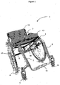
- Figure 1 shows a wheelchair 1 according to the present invention.
- the wheelchair is hand-driven.
- a seat 2 for accommodating a wheelchair user, said seat comprising a seat surface 13 and a backrest 12.
- the perspective of a user seated in the wheelchair defines the left, right, front and rear sides of the wheelchair.
- Figure 1 represents a front view
- the right side of Figure 1 corresponds to the left side of the wheelchair and vice versa.
- Left and right main wheels 3, 4 are connected at their central points by a transversal axle 5.
- the wheels are equipped with parallel-grip-rings for manual propulsion.
- the frame tubes are bent, with their ends extending downwardly in the front part of the wheelchair. Laterally at said front ends, support structures for lodging left and right castor wheels 8, 9, respectively, are attached, for example by welding, to each left and right frame tube 6, 7.
- a U-shaped foot-rest 11 connects the left and right frame tubes 6, 7 at their bottom ends.
- the outer tube circumference of the foot-rest 11 is equal or slightly smaller than the inner circumference of the left and right main frame tubes at their bottom ends. In this way, the left and right lateral parts of the foot-rest 11 telescopically slide within the left and right frame tubes 6, 7, the latter being arranged in parallel at their bottom ends.
- a number of holes present in the left and right tubes of the U-shaped foot-rest allows for adjustment of foot-rest height, by tightening a screw extending from a borings in the left and right frame tubes, 6, 7, respectively, through said holes in the left and right lateral tubes of the foot rest.
- the left and right frame tubes, 6, 7, converge with their rear upper ends, where they are fixed to axle 5 of the wheelchair 1.
- a support device 10 comprising a spring can bee seen.
- said spring is linked to a tube 15, which is part of the seat chassis, namely of the rear part of said chassis.
- each left and right frame tube, 6, 7, is attached to the chassis of the seat of the wheelchair, namely to left and right seat tubes, respectively.
- the seat 2 is supported at three positions, namely at a central position, substantially vertically above the axle 5, by the support device 10, and at two lateral positions, near the front of the upper parts of the frames tubes 6, 7, respectively, corresponding to the left and right sides towards the front of the seat.
- the unusual arrangement of the left and right frame tubes, being attached with their rear ends close to the middle point of the axle 5, reminds of legs of a spider.
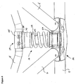
- the first embodiment of the support device 10 of the present invention comprises an intermediate element, located between a pivot part 23, pivoting into a seat provided in a central part 20 fixed to the axle 5, and a fixing element 24 attached to the seat tube 15.
- the intermediate element comprises a spring 28 and a shock absorber element 29, the shock absorber element, for example an elastomer element, being located in the lacuna provided by the spiral turns of the spring 28.
- the spring 28 and the shock absorber element 29 are seated on pivot part 23, which is pivotally attached to the axle 5 by means of a centre part 20 mounted around the axle 5 and which will be described in detail later.
- the pivoting axis of pivot part 23 is parallel to axle 5.
- the centre part 20 also harbours, on left and right sides of the pivot part 23, the rear ends of the left and right frame tubes, 6 and 7, respectively.
- a longitudinal slot 17 in the centre part 20 is visible extending from left to right along the axle 5. This slot is necessary for tightening the centre part 20 around axle 5, while permitting some adjustment of the centre part to the diameter of the axle 5.
- a fixing screw 30 extends along the central axis of the support device, through a central hole provided in the pivot part 23 and a central boring 95 provided in the shock absorber element 29.
- the screw 30 is anchored in the boring 95 of lower part 26 of fixing element 24, the head 31 of the screw 30 abutting upon an inner sleeve 35 of pivot part 23.
- the screw 30, when tightened by a thread or nut present in fixing element 24, attaches the support device of the invention 23, 10, 24 to the seat tube 15, the pivot part being itself pivotally attached to the centre part 20 attached on the middle of axle 5.
- a ring 32 is preferably located between the head 31 of screw 30 and sleeve 35.
- left and right pins 36, 37 are seated in left and right borings, 38, 39, respectively, provided in the centre part 20 and oriented in parallel to axle 5.
- these left and right borings, 38, 39 are located at the bottom of left and right supports 66, 77, intended to receive the left and right frame tubes, respectively.
- the pins 36, 37 extend from their respective borings 38, 39 in the centre part 20 towards each other, into corresponding borings provided in the centrally located pivot part 23, thus providing a pivoting articulation for the pivot part 23.
- pins 36, 37 penetrate into a substantial part of pivot part 23, to provide sufficient footing for the pivoting articulation, they do not extend through it entirely, but leave a free space 33 in the centre, to permit access to the head 31 of screw 30.
- the free space 33 is helpful when exchanging the intermediate element 10.
- the free space 33 may be temporarily occupied by the head 31 of screw 30, when the latter is descending upon compression of spring 28 and shock absorber element 29, upon absorption of shocks experienced by the wheelchair.
- the left and right pins 36, 37 each comprise a head, 42, 43, each of which is threaded in the lateral boring 45, 46, the central borings 38, 39, housing the axel-forming part of the pins 36, 37.
- pivot part 23 comprises, on its top vertical end, even and substantially horizontal surfaces 47 and 48, on which the shock absorber element 29 and spring 28 bear.
- Both surfaces 47, 48 if viewed from top, have the form of a ring, with surface 47, on which the shock absorber element 29 bears, having a central opening for the passage of the screw 30.
- Surface 48 is situated laterally and lower than surface 47 with a radial dimension substantially corresponding to the thickness of the spring 30.
- the bottom end of lower part 26 of fixing element 24 substantially mirrors the dimensions of the top vertical end of pivot part 23, thus providing ring-shaped surfaces 49 and 53.
- spring 28 With screw 30 anchored in fixing element 24, spring 28 is stably clamped between surfaces 48 and 53 of the pivot part and the fixing element, respectively. Lateral displacement of the spring being prevented by the vertical offset of surfaces 47 and 49, respectively.
- the shock absorber element 29, on the other hand, is clamped between inner, ring-shaped surfaces 47 and 49, and further stabilised by annular protrusions 54 and 55 of the pivot part 23 at the shock absorber element's bottom end and on the fixing element 24 at the shock absorber element's upper end, respectively, said protrusions preventing lateral displacement of the shock absorber element 29.
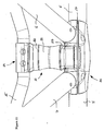
- the central part 20 is better represented on Figures 4A, 4B and 4C . It can be seen that the central part 20 is provided in a single piece. It comprises a free space 16 intended to receive the pivot part 23 and which is sufficiently deep to allow for pivoting of the latter. This free space 16 is actually created by the gap between the left and right cylindrical structures 66, 77, intended to receive the left and right frame tubes 6 and 7, respectively. Openings of the left and right borings 38, 39, are also visible. The distal ends of the cylindrical structures 66, 77, have diameters slightly smaller or equal to the internal diameter of the left and right frame tubes, 6, 7, respectively, permitting telescopically setting said frame tubes onto said cylindrical support structures.
- each support structure 66, 77 allow for detachably attaching said frame tubes 6, 7 to said support structures 66, 77, for example by means of a screw or a pushable pin.
- the cylindrical hollow 63, designed to harbour axle 5 is also visible. Also slot 17 and opening 70 are visible.
- Left and right borings 65, 67 are intended to house screws to permit tightening of the central part 20 around axle 5 (see Figure 3 ), while diminishing the breadth of slot 17 ( Figure 4A ).
- Figure 4C shows the vertical orientation of boring 67 and the position of slot 17, thus illustrating that central part 20 will be tightened around axle 5 when a screw is tightened in boring 67, compressing slot 17 and thus diminishing the dimension of cylindrical hollow 63, intended to harbour axle 5.
- a thread for said screw (both not shown in Figure 4C ) may be present in the upper end of boring 67.
- FIGS 5A and 5B show further details of pivot part 23.
- Ridge 76 illustrates the vertical offset between ring-shaped surfaces 47 and 48, which is relevant for preventing lateral movements of intermediate part 10, when placed between pivot part 23 and the lower part 26 of fixing element 24 (not shown).
- Borings 72 and 73 are intended to harbour the central ends of pins 36, 37.
- the concave surface 80 having a circular form incross-section, is visible.
- This concave surface 80 is designed to fit with the diameter of the seat tube 15 (not shown) and, when harbouring said tube, covers about half of its circumference.
- the fixing element 24 has a hinge-joint configuration, with a hinge being formed between lower part 26 and upper part 25, by means of hinge-joint elements 81, 82, with a common central axis, but leaving a gap between them for inserting a corresponding hinge-joint provided in the upper part 25 ( Figure 7 ).
- Borings 83 are provided in the other (front) side of concave surface 80, which comprise threads so as to fix said upper part 25 by means of screws to said lower part 26 at the front side of the fixing element 24 (not shown).
- the upper part 25 mainly forms a concave surface 90, which is intended to harbour about half of the circumference of the seat tube 15 (not shown), the other half being covered by concave surface 80 of lower part 26 (see Figures 6A and 6B ).
- the hinge-joint element 84 visible in a central position at the rear part of the upper part 25 is adjusted to fit between hinge-joint elements 81, 82, of lower part 26 and to thus form the hinge joint with the latter, a pin or axle being placed so as to extend through holes 85 and 86 of the hinge-joint elements of the upper and lower parts 25 and 26, respectively.
- FIGS 8 show a second embodiment of the support device of the present invention.
- a washer 40 is placed between the intermediate element comprising the spring 28 and the shock absorber element 29, and the lower part 26 of the fixing element 24. With the washer 40 at this position, the distance between axle 5 and seat tube 15 is increased by the thickness of the washer 40, thus increasing the rear seat height of the wheelchair.
- washers of various thickness can be used for increasing rear seat height.
- the washer could also be used to keep rear seat height constant when a spring and/or shock absorber element smaller than that shown in Figure 2 is used. Springs of different strengths can thus be employed without affecting rear seat height. Accordingly, the combination of intermediate element 10 and washer 40 allows various adjustments according to the wheelchair user's preferences.
- Figure 9 and 10 show a third embodiment of the support device of the present invention.
- the intermediate element consists in a rigid element 50.
- the rigid element 50 is put in place when the spring and shock absorbing function is not desired.
- the rigid element 50 resembles a hollow column, with the screw 30 extending along the central, vertical axe of said column.
- rear seat height is adjusted to a relatively low level, rigid element 50 being shorter than the spring 28 in Figure 3 .
- small washers 51 are situated between the head 31 of screw 30 and sleeve 35, to account for the length of screw 30.
- a shorter screw 30 could, of course, be used with the same result.
- the rear seat height may be adjusted by using rigid elements of different lengths and/or by using washers as discussed hereunder.
- Figure 11 and 12 show a fourth embodiment similar to that of Figures 9 and 10 , but with increased rear seat height, due to the presence of washer 60 placed above rigid element 50, and below fixing element 24.
- the washer is clamped, together with the rigid element 50, by screw 30 (not visible), between pivot part 23 and fixing element 24, thus heightening the overall position of seat tube 15 with respect to axle 5, and, in consequence with respect to the ground on which the wheelchair is placed.
- washer 60 is to increase the distance provided by intermediate element, here rigid element 50.
- intermediate element here rigid element 50.
- only one instead of two small washers 51 is placed between head 31 of screw 30 and the inner sleeve 35 of pivot part 23, because of the increased distance, resulting in increased rear seat height, provided by the combination of rigid element 50 and washer 60.
- the washer 60 has an upper profile that fits the profile of the lower end of lower part 26 of fixing element 24, and a lower profile that fits the profile of the upper end of intermediate element, here rigid element 50.
- Figure 13 shows a fifth embodiment of the support device of the present invention, comprising two washers 60, 100 positioned directly above and below, respectively, of rigid element 50, thus further increasing rear seat height.
- the lower washer 100 is, in this case, placed between pivot part 23 and rigid element 50.
- the support device of the present invention allows adjustment of rear seat height and of absorption characteristics.
- the intermediate element (28, 29; 50) can be easily removed, replaced and or supplemented with washers 40 to increase rear seat height.
- the head 31 of screw 30, situated in pivot part 23, is accessible and can be loosened with a suitable tool, by the wheelchair user or technical staff of a wheelchair vendor.
- Screw 30 being loosened, fixing element 24 can be manually separated from said screw and pivot part 23.
- the latter can be pivoted towards the front of the wheelchair and the intermediate element, for example a spring 28 and a shock absorber 29 may be further supplemented with a washer 40, or may be replaced by a rigid element 50, with or without washer 60, 100.
- pivot part 23 Once all desired replacements or supplements being put on pivot part 23, the latter is pivoted back to its substantially vertical position and the lower part 26 of fixing element 24 is fitted unto exchanged and/or supplemented intermediate element. Then, screw 30 is again tightened to clamp the intermediate element, with or without washers, between pivot part 23 and fixing element 24, thus connecting the seat tube 15 to axle 5.
- a spring 28 can be used alone, but preferably in combination with a shock absorber element 29, the latter having the purpose of absorbing shocks.
- springs of different strengths and elastomers of different materials, such as rubbers, or gas filled shock absorbers exhibiting different absorbing characteristics may be selected according to the wheelchair users preferences or physical properties, for example according to the weight of the wheelchair user.
- rigid elements 50 may be used to provide intermediate element, thus minimizing shock absorption and cushioning properties of the support device and providing an overall wheelchair nearly devoid of these properties. The later may be desired if the wheelchair is to be used on even, flat surfaces and/or if loss of kinetic energy by absorption is to be prevented, for example in wheelchair races.
Landscapes
- Health & Medical Sciences (AREA)
- Life Sciences & Earth Sciences (AREA)
- Animal Behavior & Ethology (AREA)
- General Health & Medical Sciences (AREA)
- Public Health (AREA)
- Veterinary Medicine (AREA)
- Handcart (AREA)
- Automatic Cycles, And Cycles In General (AREA)
- Devices For Medical Bathing And Washing (AREA)
- Carriages For Children, Sleds, And Other Hand-Operated Vehicles (AREA)
Description
- The present invention relates to a support device for supporting a seat on an axle of a wheelchair and to a wheelchair comprising the device.
- The present invention seeks to improve comfort for wheelchair users and in particular to solve the problem of shock loads transmission into the spinal and skeleton parts of the human body. Furthermore, the present invention seeks to provide devices and components for wheelchairs that take individual preferences of a wheelchair user into account. An objective is thus to provide a wheelchair or wheelchair components that permit easy adaptions to the surface on which said wheelchair is intended to roll or to other varying circumstances. In particular, it is an objective of providing components for a wheelchair, which can easily be replaced according to the wheelchair user's needs, preferably by the wheelchair user alone.
- Accordingly, it is an objective of the present invention to provide means for adjusting the height of the seat surface of a wheelchair. It is also an objective to provide for the possibility of adjusting the shock absorbing and springing characteristics of a wheelchair. The latter may be important to adapt the wheelchair according to the weight of the user, according to the surface on which the wheelchair is rolling and also to individual preferences of the user.
- In general, the present invention relates to non-motorized wheelchairs. Such wheelchairs are generally hand driven and are advantageously light in weight. It is thus a further objective to provide a wheelchair that is optimised in terms of material utilisation and provides for high stability at relatively low weight.
-
US 6,168,178 describes a wheelchair in which the chassis of the wheelchair can be converted from a rigid chassis to a suspension chassis and vice versa. However, the conversion is quite labour-intensive and complex as it implies the removal or addition of several components. Furthermore, the device disclosed in this reference does not allow to adjust further parameters of the wheelchair, such as seat height. Furthermore, mechanical forces are disadvantageously distributed in this device. -
BE 529 233 - The present invention concerns a support device according to
claim 1. - In another aspect, the present invention provides a wheelchair according to
claim 13. - Preferred embodiments of the present invention are specified in the appended dependent claims, as well as in the detailed description herein below.
-
-
Figure 1 shows a three quarter bottom front view of a wheelchair comprising a fist embodiment of the support device of the invention. -
Figure 2 is a close front view of a first embodiment of a support device according to the present invention. -
Figure 3 is a longitudinal vertical section of the embodiment ofFigure 2 . -
Figure 4A is a perspective view of a central part for pivotally lodging the support device of the present invention. -
Figure 4B is a horizontal section of the central part ofFigure 4A . -
Figure 4C is a vertical, lateral section of the central part at line B-B shown inFigure 4B . -
Figure 5A is a perspective view of the pivot part of the support device of the present invention. -
Figure 5B is a longitudinal vertical section of the pivot part ofFigure 5A . -
Figure 6A is a perspective view of the lower part of the fixing element of the support device of the present invention. -
Figure 6B is a vertical transverse section of the lower part ofFigure 6A . -
Figures 7A is a perspective view of the upper part of the fixing element of the support device of the present invention. -
Figures 7B is a vertical transverse section of the upper part ofFigure 7A . -
Figure 8 is a close front view of a second embodiment of a support device according to the present invention. -
Figure 9 is a close front view of a third embodiment of a support device according to the present invention. -
Figure 10 is a longitudinal vertical section of the embodiment ofFigure 9 . -
Figure 11 is a close front view of a fourth embodiment of a support device according to the present invention. -
Figure 12 is a longitudinal vertical section of the embodiment ofFigure 11 . -
Figure 13 is a close front view of a fifth embodiment of a support device according to the present invention. - Various embodiments according to the present invention will be now described by way of example with reference to the appended drawing figures.
-
Figure 1 shows awheelchair 1 according to the present invention. The wheelchair is hand-driven. As usual in wheelchairs, there is aseat 2 for accommodating a wheelchair user, said seat comprising aseat surface 13 and abackrest 12. The perspective of a user seated in the wheelchair defines the left, right, front and rear sides of the wheelchair. Given thatFigure 1 represents a front view, the right side ofFigure 1 corresponds to the left side of the wheelchair and vice versa. Left and rightmain wheels transversal axle 5. The wheels are equipped with parallel-grip-rings for manual propulsion. - Left and
right frame tubes - The frame tubes are bent, with their ends extending downwardly in the front part of the wheelchair. Laterally at said front ends, support structures for lodging left and
right castor wheels right frame tube rest 11 connects the left andright frame tubes rest 11 is equal or slightly smaller than the inner circumference of the left and right main frame tubes at their bottom ends. In this way, the left and right lateral parts of the foot-rest 11 telescopically slide within the left andright frame tubes - As is also visible in
Figure 1 , the left and right frame tubes, 6, 7, converge with their rear upper ends, where they are fixed toaxle 5 of thewheelchair 1. In a position which lies in between the rear ends of thetubes axle 5, asupport device 10 comprising a spring can bee seen. At its upper end, said spring is linked to atube 15, which is part of the seat chassis, namely of the rear part of said chassis. - From
Figure 1 the role of the twoframe tubes axle 5, the overall framework of the wheelchair. As indicated, both frame tubes are attached with their rear part to the left and the right side of the middle point of theaxle 5, leaving the middle zone of theaxle 5 for bearing the support device. From their rear ends, the frame tubes extend forwardly and slightly upwardly, diverging towards the lateral left and right front ends of the seat, where they bend downwardly. Shortly before bending downwards, each left and right frame tube, 6, 7, is attached to the chassis of the seat of the wheelchair, namely to left and right seat tubes, respectively. - Accordingly, the
seat 2 is supported at three positions, namely at a central position, substantially vertically above theaxle 5, by thesupport device 10, and at two lateral positions, near the front of the upper parts of theframes tubes axle 5, reminds of legs of a spider. - As illustrated on
Figures 2 and3 the first embodiment of thesupport device 10 of the present invention comprises an intermediate element, located between apivot part 23, pivoting into a seat provided in acentral part 20 fixed to theaxle 5, and a fixingelement 24 attached to theseat tube 15. The intermediate element comprises aspring 28 and ashock absorber element 29, the shock absorber element, for example an elastomer element, being located in the lacuna provided by the spiral turns of thespring 28. At their bottom ends, thespring 28 and theshock absorber element 29 are seated onpivot part 23, which is pivotally attached to theaxle 5 by means of acentre part 20 mounted around theaxle 5 and which will be described in detail later. The pivoting axis ofpivot part 23 is parallel toaxle 5. Thecentre part 20 also harbours, on left and right sides of thepivot part 23, the rear ends of the left and right frame tubes, 6 and 7, respectively. Alongitudinal slot 17 in thecentre part 20 is visible extending from left to right along theaxle 5. This slot is necessary for tightening thecentre part 20 aroundaxle 5, while permitting some adjustment of the centre part to the diameter of theaxle 5. - At their top ends, the
spring 28 andshock absorber element 29 abut to thelower part 26 of fixingelement 24, which will also be described in more detail later. - As can be seen in
Figure 3 , a fixingscrew 30 extends along the central axis of the support device, through a central hole provided in thepivot part 23 and acentral boring 95 provided in theshock absorber element 29. Thescrew 30 is anchored in the boring 95 oflower part 26 of fixingelement 24, thehead 31 of thescrew 30 abutting upon aninner sleeve 35 ofpivot part 23. In this way, thescrew 30, when tightened by a thread or nut present in fixingelement 24, attaches the support device of theinvention seat tube 15, the pivot part being itself pivotally attached to thecentre part 20 attached on the middle ofaxle 5. Aring 32 is preferably located between thehead 31 ofscrew 30 andsleeve 35. - With respect to the pivotal attachment of the
pivot part 23, left andright pins centre part 20 and oriented in parallel toaxle 5. As is better visible inFigure 4A to 4C , these left and right borings, 38, 39, are located at the bottom of left andright supports - The
pins respective borings centre part 20 towards each other, into corresponding borings provided in the centrally locatedpivot part 23, thus providing a pivoting articulation for thepivot part 23. - While
pins pivot part 23, to provide sufficient footing for the pivoting articulation, they do not extend through it entirely, but leave afree space 33 in the centre, to permit access to thehead 31 ofscrew 30. As will be discussed further below, thefree space 33 is helpful when exchanging theintermediate element 10. Furthermore, thefree space 33 may be temporarily occupied by thehead 31 ofscrew 30, when the latter is descending upon compression ofspring 28 andshock absorber element 29, upon absorption of shocks experienced by the wheelchair. - The left and
right pins central borings pins -
Figure 3 also shows thatpivot part 23 comprises, on its top vertical end, even and substantiallyhorizontal surfaces shock absorber element 29 andspring 28 bear. Both surfaces 47, 48, if viewed from top, have the form of a ring, withsurface 47, on which theshock absorber element 29 bears, having a central opening for the passage of thescrew 30.Surface 48 is situated laterally and lower thansurface 47 with a radial dimension substantially corresponding to the thickness of thespring 30. - The bottom end of
lower part 26 of fixingelement 24 substantially mirrors the dimensions of the top vertical end ofpivot part 23, thus providing ring-shapedsurfaces screw 30 anchored in fixingelement 24,spring 28 is stably clamped betweensurfaces surfaces shock absorber element 29, on the other hand, is clamped between inner, ring-shapedsurfaces annular protrusions pivot part 23 at the shock absorber element's bottom end and on the fixingelement 24 at the shock absorber element's upper end, respectively, said protrusions preventing lateral displacement of theshock absorber element 29. - The
central part 20 is better represented onFigures 4A, 4B and 4C . It can be seen that thecentral part 20 is provided in a single piece. It comprises afree space 16 intended to receive thepivot part 23 and which is sufficiently deep to allow for pivoting of the latter. Thisfree space 16 is actually created by the gap between the left and rightcylindrical structures right frame tubes right borings cylindrical structures right holes support structure frame tubes support structures axle 5 is also visible. Also slot 17 andopening 70 are visible. - Left and
right borings central part 20 around axle 5 (seeFigure 3 ), while diminishing the breadth of slot 17 (Figure 4A ). -
Figure 4C shows the vertical orientation of boring 67 and the position ofslot 17, thus illustrating thatcentral part 20 will be tightened aroundaxle 5 when a screw is tightened in boring 67, compressingslot 17 and thus diminishing the dimension of cylindrical hollow 63, intended to harbouraxle 5. A thread for said screw (both not shown inFigure 4C ) may be present in the upper end of boring 67. -
Figures 5A and 5B show further details ofpivot part 23. Anannular protrusion 54 surrounding boring 75, in which the screw 30 (not visible) is to be held, is provided on top of pivot part.Ridge 76 illustrates the vertical offset between ring-shapedsurfaces intermediate part 10, when placed betweenpivot part 23 and thelower part 26 of fixing element 24 (not shown).Borings pins - Details of the
lower part 26 andupper part 25 composing the fixingelement 24 forming a clamp aroundseat tube 15 are shown inFigures 6A and 6B and inFigures 7A and 7B respectively. - In
Figure 6A , theconcave surface 80, having a circular form incross-section, is visible. Thisconcave surface 80 is designed to fit with the diameter of the seat tube 15 (not shown) and, when harbouring said tube, covers about half of its circumference. In the centre of saidconcave surface 80 the extension of boring 95 is visible, in which screw 30 is to be harboured and tightened by means of a thread. The fixingelement 24 has a hinge-joint configuration, with a hinge being formed betweenlower part 26 andupper part 25, by means of hinge-joint elements Figure 7 ).Borings 83 are provided in the other (front) side ofconcave surface 80, which comprise threads so as to fix saidupper part 25 by means of screws to saidlower part 26 at the front side of the fixing element 24 (not shown). - In
Figure 6B , the situation of the even ring-shapedsurfaces protrusion 55 is visible, in which a boring 95 for harbouring thescrew 30 extends (not shown). The section provided inFigure 6B is slightly lateral and extends vertically along one of theborings 83, thus showing the orientation of the latter in thelower part 26. - As illustrated by
Figures 7A and 7B , theupper part 25 mainly forms aconcave surface 90, which is intended to harbour about half of the circumference of the seat tube 15 (not shown), the other half being covered byconcave surface 80 of lower part 26 (seeFigures 6A and 6B ). The hinge-joint element 84, visible in a central position at the rear part of theupper part 25 is adjusted to fit between hinge-joint elements lower part 26 and to thus form the hinge joint with the latter, a pin or axle being placed so as to extend throughholes 85 and 86 of the hinge-joint elements of the upper andlower parts Figures 7A and 7B , theopenings 27 for a screw to be placed are shown, with the head of said screw abutting againstsurface 87. Said screw will extend through borings 83 (Figure 6A and B) and thus permit tightening fixingelement 24 aroundseat tube 15. -
Figures 8 show a second embodiment of the support device of the present invention. In this embodiment, awasher 40 is placed between the intermediate element comprising thespring 28 and theshock absorber element 29, and thelower part 26 of the fixingelement 24. With thewasher 40 at this position, the distance betweenaxle 5 andseat tube 15 is increased by the thickness of thewasher 40, thus increasing the rear seat height of the wheelchair. - It is clear that washers of various thickness can be used for increasing rear seat height. However, the washer could also be used to keep rear seat height constant when a spring and/or shock absorber element smaller than that shown in
Figure 2 is used. Springs of different strengths can thus be employed without affecting rear seat height. Accordingly, the combination ofintermediate element 10 andwasher 40 allows various adjustments according to the wheelchair user's preferences. -
Figure 9 and10 show a third embodiment of the support device of the present invention. Instead of a spring/shock absorber element, the intermediate element consists in arigid element 50. Therigid element 50 is put in place when the spring and shock absorbing function is not desired. - As is better shown in
Figure 10 , therigid element 50 resembles a hollow column, with thescrew 30 extending along the central, vertical axe of said column. In this embodiment, rear seat height is adjusted to a relatively low level,rigid element 50 being shorter than thespring 28 inFigure 3 . For this reason,small washers 51 are situated between thehead 31 ofscrew 30 andsleeve 35, to account for the length ofscrew 30. Instead ofsmall washers 51, ashorter screw 30 could, of course, be used with the same result. However, as the situation is inFigure 10 , thehead 31, abutting against aring 52, for example a washer, situated belowsmall washers 51, is now situated lower inpivot part 23 and occupies nearly all space (33 inFigure 3 ) provided between the central ends ofpins - Similar to the situation in
Figure 3 , the vertically offset, ring-shapedsurfaces pivot part lower part 26 of fixingelement 24 provide for the lateral stabilisation of theintermediate element 10, hererigid element 50. - The rear seat height may be adjusted by using rigid elements of different lengths and/or by using washers as discussed hereunder.
-
Figure 11 and12 show a fourth embodiment similar to that ofFigures 9 and10 , but with increased rear seat height, due to the presence ofwasher 60 placed aboverigid element 50, and below fixingelement 24. As in the embodiments with the spring and/or the shock absorber element, the washer is clamped, together with therigid element 50, by screw 30 (not visible), betweenpivot part 23 and fixingelement 24, thus heightening the overall position ofseat tube 15 with respect toaxle 5, and, in consequence with respect to the ground on which the wheelchair is placed. - The purpose of
washer 60 is to increase the distance provided by intermediate element, hererigid element 50. In this embodiment, contrary to the one ofFigure 10 , only one instead of twosmall washers 51 is placed betweenhead 31 ofscrew 30 and theinner sleeve 35 ofpivot part 23, because of the increased distance, resulting in increased rear seat height, provided by the combination ofrigid element 50 andwasher 60. Thewasher 60 has an upper profile that fits the profile of the lower end oflower part 26 of fixingelement 24, and a lower profile that fits the profile of the upper end of intermediate element, hererigid element 50. -
Figure 13 shows a fifth embodiment of the support device of the present invention, comprising twowashers rigid element 50, thus further increasing rear seat height. Thelower washer 100 is, in this case, placed betweenpivot part 23 andrigid element 50. - The advantages of the support device of the present invention in terms of adjusting parameters of the wheelchair will now be described.
- The support device of the present invention allows adjustment of rear seat height and of absorption characteristics.
- Accordingly, the intermediate element (28, 29; 50) can be easily removed, replaced and or supplemented with
washers 40 to increase rear seat height. To this end, thehead 31 ofscrew 30, situated inpivot part 23, is accessible and can be loosened with a suitable tool, by the wheelchair user or technical staff of a wheelchair vendor.Screw 30 being loosened, fixingelement 24 can be manually separated from said screw and pivotpart 23. The latter can be pivoted towards the front of the wheelchair and the intermediate element, for example aspring 28 and ashock absorber 29 may be further supplemented with awasher 40, or may be replaced by arigid element 50, with or withoutwasher pivot part 23, the latter is pivoted back to its substantially vertical position and thelower part 26 of fixingelement 24 is fitted unto exchanged and/or supplemented intermediate element. Then, screw 30 is again tightened to clamp the intermediate element, with or without washers, betweenpivot part 23 and fixingelement 24, thus connecting theseat tube 15 toaxle 5. - Absorption parameters of the wheelchair may be adjusted by selecting suitable intermediate elements. A
spring 28 can be used alone, but preferably in combination with ashock absorber element 29, the latter having the purpose of absorbing shocks. Of course, springs of different strengths and elastomers of different materials, such as rubbers, or gas filled shock absorbers exhibiting different absorbing characteristics may be selected according to the wheelchair users preferences or physical properties, for example according to the weight of the wheelchair user. Alsorigid elements 50 may be used to provide intermediate element, thus minimizing shock absorption and cushioning properties of the support device and providing an overall wheelchair nearly devoid of these properties. The later may be desired if the wheelchair is to be used on even, flat surfaces and/or if loss of kinetic energy by absorption is to be prevented, for example in wheelchair races. - It should further be noted that the above described arrangement combining the intermediate element (
spring 28 and shock absorber 29) with the related design of the left andright frame tubes
Claims (13)
- A support device (10) for supporting a seat (2) on an axle (5) of a wheelchair (1), comprising an exchangeable intermediate element (28, 29; 50) detachably fixed at one of its ends to a chassis of the seat (2) and at its other end to the axle (5), said intermediate element determining damping characteristics of the wheelchair and the height of a rear part of the seat, and wherein the intermediate element (28, 29; 50) can be selected according to preferences of a user of the wheelchair to adjust said dampening characteristics and said height of the rear part of the seat, characterized in that it further comprises a pivot part (23) to be pivotably fixed to a centre part (20), said centre part (20) being rigidly and detachably attachable to the axle (5), and a fixing element (24) suitable for fixing the support device to the chassis of the seat (2), wherein the intermediate element (28, 29; 50) is situated between the pivot part (23) and the fixing element (24).
- The support device (10) of claim 1, wherein said intermediate element is arranged as part of said support device so as to be readily removable by manipulation of one screw.
- The support device (10) of claims 1 or 2, wherein a screw, with the intermediate element in place, is guided in parallel, preferably coaxially to the longitudinal direction of the intermediate element.
- The support device (10) of any one of the preceding claims, wherein the exchangeable intermediate element is pivotally attached on the axle (5).
- The support device (10) of any one of the preceding claims, further comprising a central boring (75, 95) extending from the pivot part (23) through the intermediate element (28, 29; 50) and to the fixing element (24), said boring housing a screw (30) for fixably and detachably connecting said pivot part (23), intermediate element (28, 29; 50) and fixing element (24).
- The support device (10) of claim 5, wherein the pivot part (23) is pivotally seated in said centre part (20) through a pair of left and right pins (36, 37) extending in parallel to the axle (5), one end of each pin being lodged in left and right borings (38, 39) of the centre part (20), respectively, an other end of each pin extending into a left and right boring (72, 73) of the pivot part (23), said pins (36, 37) thus providing a pivot axis for the pivot part (23).
- The support device (10) of any one of the preceding claims, wherein the intermediate element (28, 29) comprises at least one elastic element.
- The support device (10) of any one of the preceding claims, wherein the intermediate element (28, 29) comprises a spring and/or a shock absorber element, in particular an elastomer element (29) located in the lacuna provided by the spiral turns of a spring (28).
- The support device (10) of any one of the preceding claims, wherein at least one washer (40; 60, 100) is located between the intermediate element (28, 29; 50) and the fixing element (24) and/or between the intermediate element (28, 29; 50) and the pivot part (23).
- The support device (10) of claim 1, in which the intermediate part is rigid.
- The support device (10) of claim 1, wherein the centre part (20) is a one single piece element.
- The support device (10) of claim 11, wherein the centre part (20) further comprises two lodgings (66, 77) for attaching two frame tubes (6, 7).
- A wheelchair (1) comprising a seat (2) and two main wheels (3, 4) connected by an axle (5) and further comprising a support device (10) according to any one of the preceding claims, wherein said support device is detachably fixed at one of its end to a chassis of the seat and at its other end to the axle (5) through its centre part (20) attached to the middle part of said axle (5), said centre part (20) being arranged to receive the rear ends of two left and right main frame tubes (6, 7) of the wheelchair.
Priority Applications (1)
| Application Number | Priority Date | Filing Date | Title |
|---|---|---|---|
| EP07826392.8A EP2063846B1 (en) | 2006-09-18 | 2007-09-14 | Support device for wheelchair |
Applications Claiming Priority (3)
| Application Number | Priority Date | Filing Date | Title |
|---|---|---|---|
| EP06405395A EP1900349A1 (en) | 2006-09-18 | 2006-09-18 | Support device for wheelchair |
| EP07826392.8A EP2063846B1 (en) | 2006-09-18 | 2007-09-14 | Support device for wheelchair |
| PCT/IB2007/053724 WO2008047261A2 (en) | 2006-09-18 | 2007-09-14 | Support device for wheelchair |
Publications (2)
| Publication Number | Publication Date |
|---|---|
| EP2063846A2 EP2063846A2 (en) | 2009-06-03 |
| EP2063846B1 true EP2063846B1 (en) | 2016-03-23 |
Family
ID=37726592
Family Applications (2)
| Application Number | Title | Priority Date | Filing Date |
|---|---|---|---|
| EP06405395A Withdrawn EP1900349A1 (en) | 2006-09-18 | 2006-09-18 | Support device for wheelchair |
| EP07826392.8A Not-in-force EP2063846B1 (en) | 2006-09-18 | 2007-09-14 | Support device for wheelchair |
Family Applications Before (1)
| Application Number | Title | Priority Date | Filing Date |
|---|---|---|---|
| EP06405395A Withdrawn EP1900349A1 (en) | 2006-09-18 | 2006-09-18 | Support device for wheelchair |
Country Status (5)
| Country | Link |
|---|---|
| US (1) | US7896376B2 (en) |
| EP (2) | EP1900349A1 (en) |
| CA (1) | CA2663213C (en) |
| NO (1) | NO20091502L (en) |
| WO (1) | WO2008047261A2 (en) |
Families Citing this family (7)
| Publication number | Priority date | Publication date | Assignee | Title |
|---|---|---|---|---|
| US8490994B2 (en) * | 2007-12-21 | 2013-07-23 | Sunrise Medical Gmbh & Co. Kg | Wheelchair frame and wheelchair with cross-brace |
| EP2174630B1 (en) * | 2008-10-10 | 2011-01-26 | Sunrise Medical GmbH & Co. KG | Wheelchair comprising a foot support |
| US8240691B2 (en) | 2009-12-02 | 2012-08-14 | Safe And Secure Products, Inc. | Manual wheelchair lift and methods of using same |
| USD654407S1 (en) * | 2010-12-23 | 2012-02-21 | Zanderlehn Karri | Vehicle |
| CA3015692A1 (en) * | 2016-02-24 | 2017-08-31 | Les Equipements Adaptes Physipro Inc. | Mid-wheel tilt-in-space manual wheelchair with constant shoulder position |
| EP3622932A1 (en) | 2018-09-14 | 2020-03-18 | Invacare International GmbH | Wheelchair, in particular wheelchair comprising a height-adjustable seat structure |
| PL3795128T3 (en) * | 2019-09-17 | 2023-02-27 | Mbl Poland Spółka Z Ograniczoną Odpowiedzialnością | Wheelchair |
Family Cites Families (21)
| Publication number | Priority date | Publication date | Assignee | Title |
|---|---|---|---|---|
| BE529233A (en) * | ||||
| US1952467A (en) * | 1932-09-01 | 1934-03-27 | Robert W Slee | Child's convertible rocker and vehicle |
| NL192246C (en) * | 1984-08-07 | 1997-04-03 | Adriaan Van Der Ende | Wheelchair. |
| US4641848A (en) * | 1985-04-15 | 1987-02-10 | Ayers Robert C | Wheelchair with rocking seat assembly |
| US4887826A (en) * | 1988-06-10 | 1989-12-19 | Kantner Richard D | Lightweight foldable wheelchair |
| US5480179A (en) * | 1992-12-01 | 1996-01-02 | Peacock; Robert T. | Wheelchair chassis |
| US5301964A (en) * | 1993-03-29 | 1994-04-12 | Papac James B | Wheelchair |
| NL9301970A (en) * | 1993-11-15 | 1995-06-01 | Hendrik Jan Ordelman | Foldable wheelchair. |
| DE19525719B4 (en) * | 1994-07-14 | 2004-08-26 | Everest & Jennings International Ltd. | Wheelchair and wheelchair frame with suspension |
| USD365788S (en) * | 1995-03-08 | 1996-01-02 | Invacare Corporation | Sport wheelchair having a T-frame |
| US6464243B2 (en) * | 1996-10-15 | 2002-10-15 | James Roche | Wheel chair |
| DE29705494U1 (en) * | 1997-03-26 | 1997-05-22 | MEYRA Wilhelm Meyer GmbH & Co KG, 32689 Kalletal | Sports wheelchair |
| US5855387A (en) * | 1997-05-01 | 1999-01-05 | Caribbean Billing International, Ltd. | Wheel chair with independent suspension |
| CH689177A5 (en) * | 1997-12-23 | 1998-11-30 | Kueschall Design Ag | Wheelchair with a closed three-dimensional frame. |
| US6168178B1 (en) * | 1998-05-02 | 2001-01-02 | Sunrise Medical Hhg Inc. | Convertible wheelchair and a method for converting a wheelchair chassis |
| DE29901471U1 (en) * | 1999-01-29 | 1999-07-22 | Sopur Medizintechnik GmbH, 69254 Malsch | Manually operated wheelchair |
| US6419253B1 (en) * | 2000-05-01 | 2002-07-16 | Invacare Corporation | Wheelchair having a double turnbuckle height adjustment |
| NL1017192C2 (en) * | 2001-01-25 | 2002-07-26 | Revab Bv | Wheelchair provided with a swiveling device near the knee of a user. |
| AU2002346747A1 (en) * | 2001-11-28 | 2003-06-10 | Johannes Heinrich Franz | A wheelchair and a chassis suitable for a wheelchair |
| US7008015B2 (en) * | 2003-12-16 | 2006-03-07 | Eric Bischoff | Seat suspension assembly |
| US6979010B1 (en) * | 2004-06-01 | 2005-12-27 | Kwapis Randal J | Sport utility wheelchair |
-
2006
- 2006-09-18 EP EP06405395A patent/EP1900349A1/en not_active Withdrawn
- 2006-12-26 US US11/645,479 patent/US7896376B2/en not_active Expired - Fee Related
-
2007
- 2007-09-14 EP EP07826392.8A patent/EP2063846B1/en not_active Not-in-force
- 2007-09-14 CA CA2663213A patent/CA2663213C/en not_active Expired - Fee Related
- 2007-09-14 WO PCT/IB2007/053724 patent/WO2008047261A2/en not_active Ceased
-
2009
- 2009-04-16 NO NO20091502A patent/NO20091502L/en not_active Application Discontinuation
Also Published As
| Publication number | Publication date |
|---|---|
| EP2063846A2 (en) | 2009-06-03 |
| NO20091502L (en) | 2009-04-16 |
| US7896376B2 (en) | 2011-03-01 |
| CA2663213A1 (en) | 2008-04-24 |
| US20080067777A1 (en) | 2008-03-20 |
| EP1900349A1 (en) | 2008-03-19 |
| CA2663213C (en) | 2015-02-24 |
| WO2008047261A3 (en) | 2008-06-26 |
| WO2008047261A2 (en) | 2008-04-24 |
Similar Documents
| Publication | Publication Date | Title |
|---|---|---|
| CA2663213C (en) | Support device for wheelchair | |
| AU738967B2 (en) | An improved wheelchair | |
| US8573622B2 (en) | Wheelchair | |
| US8540314B2 (en) | Flex chair | |
| US6168178B1 (en) | Convertible wheelchair and a method for converting a wheelchair chassis | |
| US20050161899A1 (en) | Bicycle auxiliary wheel attachment | |
| WO2007119242A2 (en) | Movement inducing module | |
| CA2094262A1 (en) | Suspension for seat of powered wheelchair | |
| US20090229405A1 (en) | Adjustable pedal joint | |
| US4572533A (en) | Wheelchair shock absorbing apparatus | |
| US7481233B2 (en) | Custom fitted crutch with two shock-absorbers | |
| US4712835A (en) | Chair with seal spring mechanism | |
| ITRM20000505A1 (en) | DYNAMIC ARTICULATED ORTHOPEDIC BACKREST. | |
| EP1295582B1 (en) | Wheelchair with a self-supporting sitting support and method for manufacturing same | |
| US8083655B2 (en) | Training device for building up the musculature of the locomotor system | |
| EP2592971B1 (en) | A sitting arrangement | |
| CN211023592U (en) | Chair with detachable seat | |
| KR20060102925A (en) | Tilting Structure of the Chair Back | |
| RU73784U1 (en) | FOLDING CHAIR | |
| CN223253145U (en) | Seat and bicycle | |
| CN209474129U (en) | A kind of regulating device of swivel chair | |
| CN218833488U (en) | Stool frame structure of fitness stool and fitness stool | |
| JP2009517285A (en) | Mounting assembly for stable mounting of seats, especially bicycle saddles | |
| EP2070500A1 (en) | Foldable wheelchair with x-shaped cross bracing frame assembly | |
| CN221569312U (en) | Damping mechanism for base of massage armchair |
Legal Events
| Date | Code | Title | Description |
|---|---|---|---|
| PUAI | Public reference made under article 153(3) epc to a published international application that has entered the european phase |
Free format text: ORIGINAL CODE: 0009012 |
|
| 17P | Request for examination filed |
Effective date: 20090406 |
|
| AK | Designated contracting states |
Kind code of ref document: A2 Designated state(s): AT BE BG CH CY CZ DE DK EE ES FI FR GB GR HU IE IS IT LI LT LU LV MC MT NL PL PT RO SE SI SK TR |
|
| AX | Request for extension of the european patent |
Extension state: AL BA HR MK RS |
|
| 17Q | First examination report despatched |
Effective date: 20120525 |
|
| DAX | Request for extension of the european patent (deleted) | ||
| GRAP | Despatch of communication of intention to grant a patent |
Free format text: ORIGINAL CODE: EPIDOSNIGR1 |
|
| INTG | Intention to grant announced |
Effective date: 20151029 |
|
| GRAS | Grant fee paid |
Free format text: ORIGINAL CODE: EPIDOSNIGR3 |
|
| GRAA | (expected) grant |
Free format text: ORIGINAL CODE: 0009210 |
|
| AK | Designated contracting states |
Kind code of ref document: B1 Designated state(s): AT BE BG CH CY CZ DE DK EE ES FI FR GB GR HU IE IS IT LI LT LU LV MC MT NL PL PT RO SE SI SK TR |
|
| REG | Reference to a national code |
Ref country code: GB Ref legal event code: FG4D |
|
| REG | Reference to a national code |
Ref country code: CH Ref legal event code: EP |
|
| REG | Reference to a national code |
Ref country code: AT Ref legal event code: REF Ref document number: 782398 Country of ref document: AT Kind code of ref document: T Effective date: 20160415 |
|
| REG | Reference to a national code |
Ref country code: IE Ref legal event code: FG4D |
|
| REG | Reference to a national code |
Ref country code: DE Ref legal event code: R096 Ref document number: 602007045449 Country of ref document: DE |
|
| REG | Reference to a national code |
Ref country code: CH Ref legal event code: NV Representative=s name: ABREMA AGENCE BREVET ET MARQUES, GANGUILLET, CH |
|
| REG | Reference to a national code |
Ref country code: LT Ref legal event code: MG4D |
|
| REG | Reference to a national code |
Ref country code: NL Ref legal event code: MP Effective date: 20160323 |
|
| PG25 | Lapsed in a contracting state [announced via postgrant information from national office to epo] |
Ref country code: FI Free format text: LAPSE BECAUSE OF FAILURE TO SUBMIT A TRANSLATION OF THE DESCRIPTION OR TO PAY THE FEE WITHIN THE PRESCRIBED TIME-LIMIT Effective date: 20160323 Ref country code: GR Free format text: LAPSE BECAUSE OF FAILURE TO SUBMIT A TRANSLATION OF THE DESCRIPTION OR TO PAY THE FEE WITHIN THE PRESCRIBED TIME-LIMIT Effective date: 20160624 |
|
| REG | Reference to a national code |
Ref country code: AT Ref legal event code: MK05 Ref document number: 782398 Country of ref document: AT Kind code of ref document: T Effective date: 20160323 |
|
| PG25 | Lapsed in a contracting state [announced via postgrant information from national office to epo] |
Ref country code: NL Free format text: LAPSE BECAUSE OF FAILURE TO SUBMIT A TRANSLATION OF THE DESCRIPTION OR TO PAY THE FEE WITHIN THE PRESCRIBED TIME-LIMIT Effective date: 20160323 Ref country code: LT Free format text: LAPSE BECAUSE OF FAILURE TO SUBMIT A TRANSLATION OF THE DESCRIPTION OR TO PAY THE FEE WITHIN THE PRESCRIBED TIME-LIMIT Effective date: 20160323 Ref country code: LV Free format text: LAPSE BECAUSE OF FAILURE TO SUBMIT A TRANSLATION OF THE DESCRIPTION OR TO PAY THE FEE WITHIN THE PRESCRIBED TIME-LIMIT Effective date: 20160323 Ref country code: SE Free format text: LAPSE BECAUSE OF FAILURE TO SUBMIT A TRANSLATION OF THE DESCRIPTION OR TO PAY THE FEE WITHIN THE PRESCRIBED TIME-LIMIT Effective date: 20160323 |
|
| REG | Reference to a national code |
Ref country code: FR Ref legal event code: PLFP Year of fee payment: 10 |
|
| PG25 | Lapsed in a contracting state [announced via postgrant information from national office to epo] |
Ref country code: PL Free format text: LAPSE BECAUSE OF FAILURE TO SUBMIT A TRANSLATION OF THE DESCRIPTION OR TO PAY THE FEE WITHIN THE PRESCRIBED TIME-LIMIT Effective date: 20160323 Ref country code: EE Free format text: LAPSE BECAUSE OF FAILURE TO SUBMIT A TRANSLATION OF THE DESCRIPTION OR TO PAY THE FEE WITHIN THE PRESCRIBED TIME-LIMIT Effective date: 20160323 Ref country code: IS Free format text: LAPSE BECAUSE OF FAILURE TO SUBMIT A TRANSLATION OF THE DESCRIPTION OR TO PAY THE FEE WITHIN THE PRESCRIBED TIME-LIMIT Effective date: 20160723 |
|
| PGFP | Annual fee paid to national office [announced via postgrant information from national office to epo] |
Ref country code: GB Payment date: 20160920 Year of fee payment: 10 Ref country code: DE Payment date: 20160921 Year of fee payment: 10 |
|
| PG25 | Lapsed in a contracting state [announced via postgrant information from national office to epo] |
Ref country code: AT Free format text: LAPSE BECAUSE OF FAILURE TO SUBMIT A TRANSLATION OF THE DESCRIPTION OR TO PAY THE FEE WITHIN THE PRESCRIBED TIME-LIMIT Effective date: 20160323 Ref country code: RO Free format text: LAPSE BECAUSE OF FAILURE TO SUBMIT A TRANSLATION OF THE DESCRIPTION OR TO PAY THE FEE WITHIN THE PRESCRIBED TIME-LIMIT Effective date: 20160323 Ref country code: PT Free format text: LAPSE BECAUSE OF FAILURE TO SUBMIT A TRANSLATION OF THE DESCRIPTION OR TO PAY THE FEE WITHIN THE PRESCRIBED TIME-LIMIT Effective date: 20160725 Ref country code: CZ Free format text: LAPSE BECAUSE OF FAILURE TO SUBMIT A TRANSLATION OF THE DESCRIPTION OR TO PAY THE FEE WITHIN THE PRESCRIBED TIME-LIMIT Effective date: 20160323 Ref country code: SK Free format text: LAPSE BECAUSE OF FAILURE TO SUBMIT A TRANSLATION OF THE DESCRIPTION OR TO PAY THE FEE WITHIN THE PRESCRIBED TIME-LIMIT Effective date: 20160323 Ref country code: ES Free format text: LAPSE BECAUSE OF FAILURE TO SUBMIT A TRANSLATION OF THE DESCRIPTION OR TO PAY THE FEE WITHIN THE PRESCRIBED TIME-LIMIT Effective date: 20160323 |
|
| PGFP | Annual fee paid to national office [announced via postgrant information from national office to epo] |
Ref country code: FR Payment date: 20160921 Year of fee payment: 10 |
|
| PG25 | Lapsed in a contracting state [announced via postgrant information from national office to epo] |
Ref country code: BE Free format text: LAPSE BECAUSE OF FAILURE TO SUBMIT A TRANSLATION OF THE DESCRIPTION OR TO PAY THE FEE WITHIN THE PRESCRIBED TIME-LIMIT Effective date: 20160323 |
|
| REG | Reference to a national code |
Ref country code: DE Ref legal event code: R097 Ref document number: 602007045449 Country of ref document: DE |
|
| PLBE | No opposition filed within time limit |
Free format text: ORIGINAL CODE: 0009261 |
|
| STAA | Information on the status of an ep patent application or granted ep patent |
Free format text: STATUS: NO OPPOSITION FILED WITHIN TIME LIMIT |
|
| PG25 | Lapsed in a contracting state [announced via postgrant information from national office to epo] |
Ref country code: DK Free format text: LAPSE BECAUSE OF FAILURE TO SUBMIT A TRANSLATION OF THE DESCRIPTION OR TO PAY THE FEE WITHIN THE PRESCRIBED TIME-LIMIT Effective date: 20160323 |
|
| PGFP | Annual fee paid to national office [announced via postgrant information from national office to epo] |
Ref country code: CH Payment date: 20161004 Year of fee payment: 10 |
|
| PG25 | Lapsed in a contracting state [announced via postgrant information from national office to epo] |
Ref country code: BG Free format text: LAPSE BECAUSE OF FAILURE TO SUBMIT A TRANSLATION OF THE DESCRIPTION OR TO PAY THE FEE WITHIN THE PRESCRIBED TIME-LIMIT Effective date: 20160623 |
|
| PGFP | Annual fee paid to national office [announced via postgrant information from national office to epo] |
Ref country code: IT Payment date: 20160922 Year of fee payment: 10 |
|
| 26N | No opposition filed |
Effective date: 20170102 |
|
| PG25 | Lapsed in a contracting state [announced via postgrant information from national office to epo] |
Ref country code: MC Free format text: LAPSE BECAUSE OF FAILURE TO SUBMIT A TRANSLATION OF THE DESCRIPTION OR TO PAY THE FEE WITHIN THE PRESCRIBED TIME-LIMIT Effective date: 20160323 |
|
| PG25 | Lapsed in a contracting state [announced via postgrant information from national office to epo] |
Ref country code: SI Free format text: LAPSE BECAUSE OF FAILURE TO SUBMIT A TRANSLATION OF THE DESCRIPTION OR TO PAY THE FEE WITHIN THE PRESCRIBED TIME-LIMIT Effective date: 20160323 |
|
| REG | Reference to a national code |
Ref country code: IE Ref legal event code: MM4A |
|
| PG25 | Lapsed in a contracting state [announced via postgrant information from national office to epo] |
Ref country code: IE Free format text: LAPSE BECAUSE OF NON-PAYMENT OF DUE FEES Effective date: 20160914 |
|
| PG25 | Lapsed in a contracting state [announced via postgrant information from national office to epo] |
Ref country code: LU Free format text: LAPSE BECAUSE OF NON-PAYMENT OF DUE FEES Effective date: 20160914 |
|
| REG | Reference to a national code |
Ref country code: DE Ref legal event code: R119 Ref document number: 602007045449 Country of ref document: DE |
|
| REG | Reference to a national code |
Ref country code: CH Ref legal event code: PL |
|
| GBPC | Gb: european patent ceased through non-payment of renewal fee |
Effective date: 20170914 |
|
| PG25 | Lapsed in a contracting state [announced via postgrant information from national office to epo] |
Ref country code: HU Free format text: LAPSE BECAUSE OF FAILURE TO SUBMIT A TRANSLATION OF THE DESCRIPTION OR TO PAY THE FEE WITHIN THE PRESCRIBED TIME-LIMIT; INVALID AB INITIO Effective date: 20070914 Ref country code: CY Free format text: LAPSE BECAUSE OF FAILURE TO SUBMIT A TRANSLATION OF THE DESCRIPTION OR TO PAY THE FEE WITHIN THE PRESCRIBED TIME-LIMIT Effective date: 20160323 |
|
| PG25 | Lapsed in a contracting state [announced via postgrant information from national office to epo] |
Ref country code: TR Free format text: LAPSE BECAUSE OF FAILURE TO SUBMIT A TRANSLATION OF THE DESCRIPTION OR TO PAY THE FEE WITHIN THE PRESCRIBED TIME-LIMIT Effective date: 20160323 Ref country code: MT Free format text: LAPSE BECAUSE OF NON-PAYMENT OF DUE FEES Effective date: 20160930 |
|
| REG | Reference to a national code |
Ref country code: FR Ref legal event code: ST Effective date: 20180531 |
|
| PG25 | Lapsed in a contracting state [announced via postgrant information from national office to epo] |
Ref country code: CH Free format text: LAPSE BECAUSE OF NON-PAYMENT OF DUE FEES Effective date: 20170930 Ref country code: GB Free format text: LAPSE BECAUSE OF NON-PAYMENT OF DUE FEES Effective date: 20170914 Ref country code: DE Free format text: LAPSE BECAUSE OF NON-PAYMENT OF DUE FEES Effective date: 20180404 Ref country code: LI Free format text: LAPSE BECAUSE OF NON-PAYMENT OF DUE FEES Effective date: 20170930 |
|
| PG25 | Lapsed in a contracting state [announced via postgrant information from national office to epo] |
Ref country code: IT Free format text: LAPSE BECAUSE OF NON-PAYMENT OF DUE FEES Effective date: 20170914 Ref country code: FR Free format text: LAPSE BECAUSE OF NON-PAYMENT OF DUE FEES Effective date: 20171002 |